EP3852834B1 - Dipositif implantable pour le traitement de l'hypervolémie - Google Patents
Dipositif implantable pour le traitement de l'hypervolémie Download PDFInfo
- Publication number
- EP3852834B1 EP3852834B1 EP19809664.6A EP19809664A EP3852834B1 EP 3852834 B1 EP3852834 B1 EP 3852834B1 EP 19809664 A EP19809664 A EP 19809664A EP 3852834 B1 EP3852834 B1 EP 3852834B1
- Authority
- EP
- European Patent Office
- Prior art keywords
- valve
- implantable device
- fluid
- chamber
- semipermeable membrane
- Prior art date
- Legal status (The legal status is an assumption and is not a legal conclusion. Google has not performed a legal analysis and makes no representation as to the accuracy of the status listed.)
- Active
Links
Images


Classifications
-
- A—HUMAN NECESSITIES
- A61—MEDICAL OR VETERINARY SCIENCE; HYGIENE
- A61M—DEVICES FOR INTRODUCING MEDIA INTO, OR ONTO, THE BODY; DEVICES FOR TRANSDUCING BODY MEDIA OR FOR TAKING MEDIA FROM THE BODY; DEVICES FOR PRODUCING OR ENDING SLEEP OR STUPOR
- A61M1/00—Suction or pumping devices for medical purposes; Devices for carrying-off, for treatment of, or for carrying-over, body-liquids; Drainage systems
- A61M1/14—Dialysis systems; Artificial kidneys; Blood oxygenators ; Reciprocating systems for treatment of body fluids, e.g. single needle systems for hemofiltration or pheresis
- A61M1/16—Dialysis systems; Artificial kidneys; Blood oxygenators ; Reciprocating systems for treatment of body fluids, e.g. single needle systems for hemofiltration or pheresis with membranes
- A61M1/1678—Dialysis systems; Artificial kidneys; Blood oxygenators ; Reciprocating systems for treatment of body fluids, e.g. single needle systems for hemofiltration or pheresis with membranes intracorporal
-
- A—HUMAN NECESSITIES
- A61—MEDICAL OR VETERINARY SCIENCE; HYGIENE
- A61M—DEVICES FOR INTRODUCING MEDIA INTO, OR ONTO, THE BODY; DEVICES FOR TRANSDUCING BODY MEDIA OR FOR TAKING MEDIA FROM THE BODY; DEVICES FOR PRODUCING OR ENDING SLEEP OR STUPOR
- A61M1/00—Suction or pumping devices for medical purposes; Devices for carrying-off, for treatment of, or for carrying-over, body-liquids; Drainage systems
- A61M1/14—Dialysis systems; Artificial kidneys; Blood oxygenators ; Reciprocating systems for treatment of body fluids, e.g. single needle systems for hemofiltration or pheresis
- A61M1/28—Peritoneal dialysis ; Other peritoneal treatment, e.g. oxygenation
-
- A—HUMAN NECESSITIES
- A61—MEDICAL OR VETERINARY SCIENCE; HYGIENE
- A61M—DEVICES FOR INTRODUCING MEDIA INTO, OR ONTO, THE BODY; DEVICES FOR TRANSDUCING BODY MEDIA OR FOR TAKING MEDIA FROM THE BODY; DEVICES FOR PRODUCING OR ENDING SLEEP OR STUPOR
- A61M1/00—Suction or pumping devices for medical purposes; Devices for carrying-off, for treatment of, or for carrying-over, body-liquids; Drainage systems
- A61M1/14—Dialysis systems; Artificial kidneys; Blood oxygenators ; Reciprocating systems for treatment of body fluids, e.g. single needle systems for hemofiltration or pheresis
- A61M1/16—Dialysis systems; Artificial kidneys; Blood oxygenators ; Reciprocating systems for treatment of body fluids, e.g. single needle systems for hemofiltration or pheresis with membranes
- A61M1/1621—Constructional aspects thereof
- A61M1/1623—Disposition or location of membranes relative to fluids
-
- A—HUMAN NECESSITIES
- A61—MEDICAL OR VETERINARY SCIENCE; HYGIENE
- A61M—DEVICES FOR INTRODUCING MEDIA INTO, OR ONTO, THE BODY; DEVICES FOR TRANSDUCING BODY MEDIA OR FOR TAKING MEDIA FROM THE BODY; DEVICES FOR PRODUCING OR ENDING SLEEP OR STUPOR
- A61M1/00—Suction or pumping devices for medical purposes; Devices for carrying-off, for treatment of, or for carrying-over, body-liquids; Drainage systems
- A61M1/14—Dialysis systems; Artificial kidneys; Blood oxygenators ; Reciprocating systems for treatment of body fluids, e.g. single needle systems for hemofiltration or pheresis
- A61M1/16—Dialysis systems; Artificial kidneys; Blood oxygenators ; Reciprocating systems for treatment of body fluids, e.g. single needle systems for hemofiltration or pheresis with membranes
- A61M1/26—Dialysis systems; Artificial kidneys; Blood oxygenators ; Reciprocating systems for treatment of body fluids, e.g. single needle systems for hemofiltration or pheresis with membranes and internal elements which are moving
- A61M1/267—Dialysis systems; Artificial kidneys; Blood oxygenators ; Reciprocating systems for treatment of body fluids, e.g. single needle systems for hemofiltration or pheresis with membranes and internal elements which are moving used for pumping
-
- A—HUMAN NECESSITIES
- A61—MEDICAL OR VETERINARY SCIENCE; HYGIENE
- A61M—DEVICES FOR INTRODUCING MEDIA INTO, OR ONTO, THE BODY; DEVICES FOR TRANSDUCING BODY MEDIA OR FOR TAKING MEDIA FROM THE BODY; DEVICES FOR PRODUCING OR ENDING SLEEP OR STUPOR
- A61M27/00—Drainage appliance for wounds or the like, i.e. wound drains, implanted drains
- A61M27/002—Implant devices for drainage of body fluids from one part of the body to another
-
- A—HUMAN NECESSITIES
- A61—MEDICAL OR VETERINARY SCIENCE; HYGIENE
- A61M—DEVICES FOR INTRODUCING MEDIA INTO, OR ONTO, THE BODY; DEVICES FOR TRANSDUCING BODY MEDIA OR FOR TAKING MEDIA FROM THE BODY; DEVICES FOR PRODUCING OR ENDING SLEEP OR STUPOR
- A61M39/00—Tubes, tube connectors, tube couplings, valves, access sites or the like, specially adapted for medical use
- A61M39/22—Valves or arrangement of valves
- A61M39/24—Check- or non-return valves
- A61M2039/2433—Valve comprising a resilient or deformable element, e.g. flap valve, deformable disc
-
- A—HUMAN NECESSITIES
- A61—MEDICAL OR VETERINARY SCIENCE; HYGIENE
- A61M—DEVICES FOR INTRODUCING MEDIA INTO, OR ONTO, THE BODY; DEVICES FOR TRANSDUCING BODY MEDIA OR FOR TAKING MEDIA FROM THE BODY; DEVICES FOR PRODUCING OR ENDING SLEEP OR STUPOR
- A61M2205/00—General characteristics of the apparatus
- A61M2205/82—Internal energy supply devices
- A61M2205/8237—Charging means
- A61M2205/8243—Charging means by induction
-
- A—HUMAN NECESSITIES
- A61—MEDICAL OR VETERINARY SCIENCE; HYGIENE
- A61M—DEVICES FOR INTRODUCING MEDIA INTO, OR ONTO, THE BODY; DEVICES FOR TRANSDUCING BODY MEDIA OR FOR TAKING MEDIA FROM THE BODY; DEVICES FOR PRODUCING OR ENDING SLEEP OR STUPOR
- A61M2210/00—Anatomical parts of the body
- A61M2210/10—Trunk
- A61M2210/1017—Peritoneal cavity
-
- A—HUMAN NECESSITIES
- A61—MEDICAL OR VETERINARY SCIENCE; HYGIENE
- A61M—DEVICES FOR INTRODUCING MEDIA INTO, OR ONTO, THE BODY; DEVICES FOR TRANSDUCING BODY MEDIA OR FOR TAKING MEDIA FROM THE BODY; DEVICES FOR PRODUCING OR ENDING SLEEP OR STUPOR
- A61M2210/00—Anatomical parts of the body
- A61M2210/10—Trunk
- A61M2210/1078—Urinary tract
Definitions
- Hypervolemia or fluid overload, is a medical condition in which the volume of blood in the intravascular compartment is in excess of normal as a result of plasma retaining too much water.
- Water can accumulate in patients suffering from chronic kidney disease, particularly in advanced stages thereof such as end-stage renal disease (“ESRD”), where the kidneys are no longer effective in filtering out water in excess of that the body needs.
- ESRD end-stage renal disease
- CHF congestive heart failure
- the volume of blood in the intravascular compartment in excess of normal can lead to fluid buildup in the peritoneal and pleural cavities causing shortness of breath, which can degrade quality of life.
- US 2012/220926 A1 relates to a medical device comprising a partially porous mesh that forms a fibrosis cage for accessing fluid from the patient upon implantation into a patient, and a pump for pumping fluid into and out of the fibrosis cage.
- an implantable device for treating hypervolemia including an expandable chamber, a rigid chamber coupled to the expandable chamber, a first valve in fluid communication with both the expandable chamber and the rigid chamber, a second valve in fluid communication with the rigid chamber and an exterior of the implantable device, and an osmotic fluid.
- the expandable chamber includes a first semipermeable membrane.
- the rigid chamber includes a piston.
- the first valve has an open position to permit fluid flow between the expandable chamber and the rigid chamber.
- the second valve has an open position to permit fluid flow from the rigid chamber to the exterior of the implantable device.
- the osmotic fluid has a higher osmotic concentration than bodily fluid.
- the osmotic fluid is designed to absorb water from the bodily fluid through the first semipermeable membrane.
- the implantable device further includes a pump.
- the pump is designed to move any fluid contents of the implantable device through the first valve in the open position or the second valve in the open position.
- the piston is configured to perform a pump-actuated pull stroke in the rigid chamber when the first valve is in the open position to pull any fluid contents of the expandable chamber into the rigid chamber.
- the piston is configured to perform a pump-actuated push stroke in the rigid chamber when the second valve is in the open position to push any fluid contents in the rigid chamber and expel permeate from the implantable device.
- At least one of the first semipermeable membrane or the second semipermeable membrane is a dialysis membrane.
- the osmotic fluid is an aqueous solution of a dissolved polymer.
- the first semipermeable membrane and the second semipermeable membrane are designed to prevent the aqueous solution of the dissolved polymer from passing through.
- the implantable device is configured for implantation in a peritoneal cavity of a patient.
- the implantable device is shunted to a ureter of the patient for elimination of excess water through the bladder.
- the implantable device further includes an inductive coil configured to couple with a complementary inductive coil of a companion device, wherein the companion device is operable to couple with mains electricity to charge or power the implantable device by induction.
- an implantable device for treating hypervolemia including an expandable chamber, a rigid chamber including a piston, a first valve between the expandable chamber and the rigid chamber, a second valve between the rigid chamber and an exterior of the rigid chamber, and a fluid within the implantable device.
- the expandable chamber includes a first semipermeable membrane over at least a portion of the expandable chamber.
- the expandable chamber is configured to expand when the fluid is disposed in the expandable chamber and osmotically absorb water through the first semipermeable membrane from a bodily fluid outside the expandable chamber having a lower osmotic concentration.
- the first valve between the expandable chamber and the rigid chamber is configured to allow the fluid to flow between the expandable chamber and the rigid chamber when the first valve is open.
- the second valve between the rigid chamber and the exterior of the rigid chamber is configured to allow the fluid to flow from the rigid chamber into a second semipermeable membrane to expel the water from the implantable device when the second valve is open.
- the implantable device further includes a pump.
- the pump is configured to operate in concert with both the first valve and the second valve.
- the pump is configured to move the fluid between the expandable chamber and the rigid chamber when the first valve is open, and the pump is configured to move the fluid from the rigid chamber to the second semipermeable membrane when the second valve is open.
- the piston is configured to perform a pump-actuated pull stroke in the rigid chamber when the first valve is open to pull the fluid from the expandable chamber into the rigid chamber.
- the piston is configured to perform a pump-actuated push stroke in the rigid chamber when the second valve is open to push the fluid from the rigid chamber through the second semipermeable membrane to expel the water from the implantable device.
- the first semipermeable membrane, the second semipermeable membrane, or both the semipermeable membranes are dialysis membranes.
- the fluid within the implantable device is an aqueous solution of a dissolved polymer.
- the fluid within the implantable device is an aqueous solution of a dissolved polymer excluded from passing through the first and second semipermeable membranes.
- the implantable device is configured for implantation in a peritoneal cavity of a patient to remove water in excess of that the patient needs.
- the implantable device is shunted to a ureter of the patient for elimination of the water in excess of that the patient needs through the bladder.
- the implantable device further includes an inductive coil configured to couple with a complementary inductive coil of a companion device operable to couple with mains electricity to charge or power the implantable device by induction.
- an implantable device for treating hypervolemia including a first expandable chamber, a second expandable chamber, a rigid chamber including a piston, a number of valves, and a fluid within the implantable device.
- the first expandable chamber includes a first semipermeable membrane over at least a portion of the first expandable chamber.
- the second expandable chamber includes a second semipermeable membrane over at least a portion of the second expandable chamber.
- Each expandable chamber of the first and second expandable chambers is configured to expand when the fluid is disposed therein and osmotically absorb water from a bodily fluid outside the implantable device having a lower osmotic concentration.
- the number of valves includes a first valve between the first expandable chamber and the rigid chamber and a second valve between the second expandable chamber and the rigid chamber. Each valve of the first and second valves is configured to allow the fluid to flow between adjacent chambers when the valve is open.
- the number of valves also includes a third valve between the rigid chamber and an exterior of the rigid chamber and a fourth valve between the rigid chamber and the exterior of the rigid chamber, wherein the third valve and the fourth valve are separated from each other by the piston.
- the third valve is configured to allow the fluid to flow from the rigid chamber into a third semipermeable membrane to expel the water from the implantable device when the third valve is open.
- the fourth valve is configured to allow the fluid to flow from the rigid chamber into a fourth semipermeable membrane to expel the water from the implantable device when the fourth valve is open.
- the implantable device further includes a pump.
- the pump is configured to operate in concert with the number of valves.
- the pump is configured to move the fluid between the first expandable chamber and the rigid chamber when the first valve is open while also moving the fluid from the rigid chamber to the fourth semipermeable membrane when the fourth valve is open.
- the pump is also configured to move the fluid between the second expandable chamber and the rigid chamber when the second valve is open while also moving the fluid from the rigid chamber to the third semipermeable membrane when the third valve is open.
- the piston is configured to perform a pump-actuated pull stroke in the rigid chamber when the first and fourth valves are open to simultaneously pull the fluid from the first expandable chamber into the rigid chamber and push the fluid from the rigid chamber through the fourth semipermeable membrane to expel the water from the implantable device.
- the piston is configured to perform a pump-actuated push stroke in the rigid chamber when the second and third valves are open to simultaneously push the fluid from the rigid chamber through the third semipermeable membrane to expel the water from the implantable device and pull the fluid from the second expandable chamber into the rigid chamber.
- each semipermeable membrane of the first, second, third, and fourth semipermeable membranes is a dialysis membranes.
- the fluid within the implantable device is an aqueous solution of a dissolved polymer.
- the fluid within the implantable device is an aqueous solution of a dissolved polymer excluded from passing through the first, second, third, and fourth semipermeable membranes.
- the implantable device is configured for implantation in a peritoneal cavity of a patient to remove water in excess of that the patient needs.
- the implantable device is shunted to a ureter of the patient for elimination of the water in excess of that the patient needs through the bladder.
- the implantable device further includes an inductive coil configured to couple with a complementary inductive coil of a companion device operable to couple with mains electricity to charge or power the implantable device by induction.
- hypervolemia or fluid overload
- ESRD end-stage renal disease
- CHF congestive heart failure
- the volume of blood in the intravascular compartment in excess of normal can lead to fluid buildup in the peritoneal and pleural cavities causing shortness of breath, which can degrade quality of life.
- the volume of blood in the intravascular compartment in excess of normal can also lead to hypertension and stress on the heart, which can exacerbate other diseases such as CHF leading to death. Therefore, managing hypervolemia is important to those suffering from the medical condition.
- an implantable device and methods thereof that address the foregoing.
- FIGS. 1A-1F illustrate a device 100 for treating hypervolemia in a number of different stages of operation in accordance with some embodiments.
- the implantable device 100 includes an expandable chamber 110, a rigid chamber 120 including a piston 122, a first valve 132 between the expandable chamber 110 and the rigid chamber 120, a second valve 134 between the rigid chamber 120 and an exterior of the rigid chamber 120, and a fluid 140 within the implantable device 100.
- the expandable chamber 110 includes a first semipermeable membrane 112 over at least a portion of the expandable chamber 110.
- the expandable chamber 110 is configured to expand when the fluid 140 is disposed in the expandable chamber 110 and osmotically absorb water into the fluid 140 through the first semipermeable membrane 112 from a bodily fluid outside the expandable chamber 110 having a lower osmotic concentration than the fluid 140. (See FIGS. 1A and 1B .)
- the first valve 132 between the expandable chamber 110 and the rigid chamber 120 is configured with an open position to allow or permit the fluid 140 to flow between the expandable chamber 110 and the rigid chamber 120 when the first valve 132 is open or in the open position. (See FIGS. 1B and 1C .)
- the second valve 134 between the rigid chamber 120 and the exterior of the rigid chamber 120 is configured with an open position to allow or permit the fluid 140 to flow from the rigid chamber 120 into a second semipermeable membrane 124 to expel the water from the implantable device 100 when the second valve 134 is open or in the open position. (See FIGS. 1D and 1E .)
- the implantable device 100 further includes a pump (not shown) such as a gear-driven piston pump to move any fluid contents of the implantable device through the implantable device 100 (e.g., through the first valve 132 or the second valve 134 when in the opened position).
- the pump is configured to operate in concert with both the first valve 132 and the second valve 134.
- the pump is configured to move the fluid 140 between the expandable chamber 110 and the rigid chamber 120 when the first valve 132 is open.
- the pump is also configured to move the fluid 140 from the rigid chamber 120 to the second semipermeable membrane 124 when the second valve 134 is open.
- the piston 122 is configured to perform a pump-actuated pull stroke in the rigid chamber 120 when the first valve 132 is open to pull any fluid contents such as the fluid 140 from the expandable chamber 110 into the rigid chamber 120.
- the piston 122 is also configured to perform a pump-actuated push stroke in the rigid chamber 120 when the second valve 134 is open to push any fluid contents such as the fluid 140 from the rigid chamber 120 through the second semipermeable membrane 124 to expel the water (as permeate) from the implantable device 100, thereby producing a retentate of the fluid 140.
- the pump-actuated push stroke can be further utilized to push the retentate of the fluid 140 from the rigid chamber 120 into the expandable chamber 110 for another cycle.
- the pump-actuated strokes can be utilized in a cycling mode of operation of the implantable device 100, in which the fluid 140 is cycled back and forth between the expandable chamber 110 and the rigid chamber 120 through the first valve 132 when in the open position.
- the cycling mode of operation ensures the fluid 140 is mixed such that the osmotic concentration of the fluid 140 near an inside surface of semipermeable membrane 124 remains high enough for osmosis through the semipermeable membrane 124.
- the cycling mode of operation of the implantable device 100 might not be necessary. That is, the activity level of the patient might be enough to mix the fluid 140 to maintain a high enough osmotic concentration of the fluid 140 near the inside surface of semipermeable membrane 124 for water osmosis through the semipermeable membrane 124.
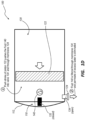
- FIG. 2 illustrates another device 200 for treating hypervolemia in accordance with some embodiments.
- the implantable device 200 includes the first expandable chamber 110, a second expandable chamber 210, the rigid chamber 120 including the piston 122, a number of valves 132, 134, 232, 234, and the fluid 140 within the implantable device 200.
- the first expandable chamber 110 includes the first semipermeable membrane 112 over at least a portion of the first expandable chamber 110 as described in reference to the implantable device 100.
- the additional second expandable chamber 210 includes a second semipermeable membrane 212 over at least a portion of the second expandable chamber 210.
- Each expandable chamber of the first and second expandable chambers 110, 210 is configured to expand when the fluid 140 is disposed therein and osmotically absorbs water from a bodily fluid outside the implantable device 200.
- the expandable chamber 110 expands when the fluid 140 in the expandable chamber 110 osmotically absorbs water into the fluid 140 through the first semipermeable membrane 112 from the bodily fluid outside the expandable chamber 110 when the bodily fluid has a lower osmotic concentration than the fluid 140
- the expandable chamber 210 expands when the fluid 140 in the expandable chamber 210 osmotically absorbs water into the fluid 140 through the second semipermeable membrane 212 from the bodily fluid outside the expandable chamber 210 when the bodily fluid has a lower osmotic concentration than the fluid 140.
- the number of valves includes the first valve 132 between the first expandable chamber 110 and the rigid chamber 120 and a second valve 232 between the second expandable chamber 210 and the rigid chamber 120.
- Each valve of the first and second valves 132, 232 is configured with an open position to allow or permit the fluid 140 to flow between adjacent chambers when the valve is open or in the open position. That is, the first valve 132 between the expandable chamber 110 and the rigid chamber 120 is configured to allow the fluid 140 to flow between the expandable chamber 110 and the rigid chamber 120 when the first valve 132 is open, and the second valve 232 between the expandable chamber 210 and the rigid chamber 120 is configured to allow the fluid 140 to flow between the expandable chamber 210 and the rigid chamber 220 when the second valve 232 is open.
- the number of valves also includes a third valve 134 between the rigid chamber 120 and an exterior of the rigid chamber 120 and a fourth valve 234 between the rigid chamber 120 and the exterior of the rigid chamber 120, wherein the third valve 134 and the fourth valve 234 are separated from each other by the piston 122.
- the third valve 134 is configured with an open position to allow or permit the fluid 140 to flow from the rigid chamber 120 into a third semipermeable membrane 124 to expel the water from the implantable device 200 when the third valve 134 is open or in the open position.
- the fourth valve 234 is configured with an open position to allow or permit the fluid 140 to flow from the rigid chamber 120 into a fourth semipermeable membrane 224 to expel the water from the implantable device 200 when the fourth valve 234 is open or in the open position.
- the implantable device 200 further includes a pump (not shown) as described in reference to the implantable device 100.
- the pump is configured to operate in concert with the number of valves 132, 134, 232, 234.
- the pump is configured to move the fluid 140 between the first expandable chamber 110 and the rigid chamber 120 when the first valve 123 is open while also moving the fluid 140 from the rigid chamber 120 to the fourth semipermeable membrane 224 when the fourth valve 234 is open.
- the pump is also configured to move the fluid 140 between the second expandable chamber 210 and the rigid chamber 120 when the second valve 232 is open while also moving the fluid 140 from the rigid chamber 210 to the third semipermeable membrane 124 when the third valve 134 is open.
- the piston 122 is configured to perform a pump-actuated pull stroke in the rigid chamber 120 when the first and fourth valves 132, 234 are open to simultaneously pull any fluid contents such as the fluid 140 from the first expandable chamber 110 into the rigid chamber 120 proximate the first expandable chamber 110 and push any fluid contents such as the fluid 140 from the rigid chamber 120 proximate the expandable chamber 210 through the fourth semipermeable membrane 224 to expel the water from the implantable device 200.
- the piston 122 is also configured to perform a pump-actuated push stroke in the rigid chamber 120 when the second and third 232, 134 valves are open to simultaneously push any fluid contents such as the fluid 140 from the rigid chamber 120 proximate the first expandable chamber 110 through the third semipermeable membrane 124 to expel the water from the implantable device 200 and pull any fluid contents such as the fluid 140 from the second expandable chamber 210 into the rigid chamber 120 proximate the second expandable chamber 210.
- the foregoing pump-actuated strokes can be further utilized with timely opening and closing of the valves to push the retentate of the fluid 140 from the rigid chamber 120 into the expandable chambers 110, 210 for additional cycles.
- the foregoing pump-actuated strokes can be further utilized in a cycling mode of operation like that of the implantable device 100.
- Each semipermeable membrane of the first, second, third, and fourth semipermeable membranes 112, 124, 212, 224 of the implantable devices 100 and 200 can have pores of a pore size that allows water to permeate through the semipermeable membrane but not larger metabolites such as polypeptides or proteins, cell fragments such as platelets, or cells such as red blood cells or white blood cells.
- the pores of the semipermeable membrane can be sized to allow ions such as Na + , K + , Ca 2+ , Mg 2+ , or Cl - to permeate through the semipermeable membrane, as well as molecules of lower molecular weight than the foregoing larger metabolites such as urea or creatinine.
- An example of such a semipermeable membrane includes, but is not limited to, a dialysis membrane.
- the fluid 140, or osmotic fluid, within the implantable device 100 or 200 can be an aqueous solution of a dissolved polymer such as poly(ethylene glycol) ("PEG”) or sodium polyacrylate, which dissolved polymer is excluded based on size from passing through any semipermeable membrane of the first, second, third, and fourth semipermeable membranes 112, 124, 212, 224.
- PEG poly(ethylene glycol)
- the initial or basal concentration of the dissolved polymer in the fluid 140 is sufficient to create an osmotic potential for removing the water in excess of that the patient needs through the first semipermeable membrane 112 or the second semipermeable membrane 212 while the implanted device 100 or 200 is implanted in the patient.
- the osmotic fluid has a higher osmotic concentration than bodily fluid, which allows the osmotic fluid to absorb water from the bodily fluid through the first semipermeable membrane 112 or the second semipermeable membrane 212 while the implanted device 100 or 200 is implanted in the patient.
- Each implantable device of the implantable device 100 and the implantable device 200 is configured for implantation in at least a peritoneal cavity of a patient to remove water that builds up in the patient's peritoneal cavity (a condition known as ascites) for one or more reasons including hypervolemia or liver disease.
- the peritoneal cavity is an advantageous location for the implantable device 100, 200 because movement of the patient allows the fluid 140 in the expandable chambers 110, 210 to keep moving fluid around, thereby encouraging movement that maintains a concentration gradient that promotes osmosis.
- the implantable device 100 can be shunted to a ureter of the patient for elimination of the water in excess of that the patient needs through the patient's bladder.
- each implantable devices of the implantable device 100 and the implantable device 200 further includes an inductive coil (not shown) configured to couple with a complementary inductive coil of a companion device such as a belt operable to couple with mains electricity to charge or power the implantable device by induction.
- a companion device such as a belt operable to couple with mains electricity to charge or power the implantable device by induction.
- the belt can be plugged in and worn during the day when the patient is resting or at night when the patient is sleeping.
Landscapes
- Health & Medical Sciences (AREA)
- Heart & Thoracic Surgery (AREA)
- Urology & Nephrology (AREA)
- Public Health (AREA)
- Animal Behavior & Ethology (AREA)
- Engineering & Computer Science (AREA)
- Anesthesiology (AREA)
- Biomedical Technology (AREA)
- Hematology (AREA)
- Life Sciences & Earth Sciences (AREA)
- Veterinary Medicine (AREA)
- General Health & Medical Sciences (AREA)
- Emergency Medicine (AREA)
- Vascular Medicine (AREA)
- Ophthalmology & Optometry (AREA)
- Otolaryngology (AREA)
- External Artificial Organs (AREA)
- Prostheses (AREA)
Claims (15)
- Dispositif implantable (100, 200) pour le traitement de l'hypervolémie, comprenant :une chambre expansible (110) incluant une première membrane semi-perméable (112) ;une chambre rigide (120) couplée à la chambre expansible (110), la chambre rigide (120) incluant un piston (122) ;un premier clapet (132) en communication fluidique avec à la fois la chambre expansible (110) et la chambre rigide (120), le premier clapet (132) présentant une position ouverte pour permettre un écoulement de fluide entre la chambre expansible (110) et la chambre rigide (120) ;un deuxième clapet (134) en communication fluidique avec la chambre rigide (120) et un extérieur du dispositif implantable (100, 200), le deuxième clapet (134) incluant une deuxième membrane semi-perméable (124), le deuxième clapet (134) présentant une position ouverte pour permettre un écoulement de fluide depuis la chambre rigide (120) vers l'extérieur du dispositif implantable (100, 200) ; etun fluide osmotique (140) présentant une concentration osmotique plus élevée que le fluide corporel, le fluide osmotique étant conçu pour absorber l'eau du fluide corporel à travers la première membrane semi-perméable (112).
- Dispositif implantable selon la revendication 1, comprenant en outre une pompe, dans lequel la pompe est conçue pour déplacer tout contenu fluide du dispositif implantable à travers le premier clapet (132) dans la position ouverte ou le deuxième clapet (134) dans la position ouverte.
- Dispositif implantable selon la revendication 1 ou la revendication 2, dans lequel le piston (122) est configuré pour mettre en oeuvre une course de traction actionnée par pompe dans la chambre rigide (120) lorsque le premier clapet (132) est dans la position ouverte pour attirer tout contenu fluide de la chambre expansible (110) dans la chambre rigide (120) ; et/ou
dans lequel le piston (122) est configuré pour mettre en oeuvre une course de poussée actionnée par pompe dans la chambre rigide (120) lorsque le deuxième clapet (134) est dans la position ouverte pour pousser tout contenu fluide de la chambre rigide (120) et expulser le perméat du dispositif implantable (100, 200). - Dispositif implantable selon l'une quelconque des revendications 1 à 3, dans lequel au moins une membrane parmi la première membrane semi-perméable (112) ou la deuxième membrane semi-perméable (124) est une membrane de dialyse.
- Dispositif implantable selon l'une quelconque des revendications 1 à 4, dans lequel le fluide osmotique (140) est une solution aqueuse d'un polymère dissous ;
facultativement dans lequel la première membrane semi-perméable (112) et la deuxième membrane semi-perméable (124) sont conçues pour empêcher la solution aqueuse du polymère dissous de traverser. - Dispositif implantable selon l'une quelconque des revendications 1 à 5, dans lequel le dispositif implantable (100, 200) est configuré pour une implantation dans une cavité péritonéale d'un patient ;
facultativement dans lequel le dispositif implantable (100, 200) est dérivé vers un uretère du patient pour une élimination de l'excès d'eau par le biais de la vessie ; - Dispositif implantable selon l'une quelconque des revendications 1 à 6, comprenant en outre une bobine d'induction configurée pour se coupler à une bobine d'induction complémentaire d'un dispositif compagnon, le dispositif compagnon pouvant fonctionner pour être couplé au réseau électrique pour charger ou alimenter le dispositif implantable par induction.
- Dispositif implantable (100, 200) pour le traitement de l'hypervolémie, comprenant :une première chambre expansible (110) incluant une première membrane semi-perméable (112) ;une deuxième chambre expansible (210) incluant une deuxième membrane semi-perméable (212) ;une chambre rigide (120) couplée à la chambre expansible (210), la chambre rigide incluant un piston (122) ;un premier clapet (132) en communication fluidique avec à la fois la première chambre expansible (110) et la chambre rigide (120), le premier clapet (132) présentant une position ouverte pour permettre un écoulement de fluide entre la première chambre expansible (110) et la chambre rigide (120) ;un deuxième clapet (134) en communication fluidique avec à la fois la deuxième chambre expansible (110) et la chambre rigide (120), le deuxième clapet (134) présentant une position ouverte pour permettre un écoulement de fluide entre la deuxième chambre expansible (210) et la chambre rigide (120) ;un troisième clapet (232) et un quatrième clapet (234) en communication fluidique avec la chambre rigide (120) et un extérieur du dispositif implantable (100, 200), le troisième clapet (232) incluant une troisième membrane semi-perméable (124), le quatrième clapet (234) incluant une quatrième membrane semi-perméable (224), le troisième clapet (232) et le quatrième clapet (234) étant séparés par le piston (122), chacun du troisième clapet (232) et du quatrième clapet (234) présentant une position ouverte pour permettre un écoulement de fluide depuis la chambre rigide (120) vers l'extérieur du dispositif implantable (100, 200) ; etun fluide osmotique (140) présentant une concentration osmotique plus élevée que le fluide corporel, le fluide osmotique étant conçu pour absorber l'eau du fluide corporel à travers la première membrane semi-perméable (112).
- Dispositif implantable selon la revendication 8, comprenant en outre une pompe, dans lequel la pompe est conçue pour déplacer tout contenu fluide du dispositif implantable à travers l'un quelconque parmi le premier clapet (132), le deuxième clapet (134), le troisième clapet (232) et le quatrième clapet (234) dans la position ouverte.
- Dispositif implantable selon la revendication 8 ou la revendication 9, dans lequel le piston (122) est configuré pour mettre en oeuvre une course de traction actionnée par pompe dans la chambre rigide (120) lorsque le premier clapet (132) est dans la position ouverte pour attirer tout contenu fluide de la première chambre expansible (110) dans la chambre rigide (120) ;
facultativement dans lequel le piston (122) est configuré pour pousser simultanément les contenus fluides depuis la chambre rigide (120) à travers le quatrième clapet (234) dans la position ouverte pour expulser le perméat du dispositif implantable (100, 200). - Dispositif implantable selon la revendication 8 ou la revendication 9, dans lequel le piston (100, 200) est configuré pour mettre en oeuvre une course de traction actionnée par pompe dans la chambre rigide (120) lorsque le deuxième clapet (134) est dans la position ouverte pour attirer tout contenu fluide de la deuxième chambre expansible dans la chambre rigide (120) ; facultativement dans lequel le piston (122) est configuré pour pousser simultanément les contenus fluides depuis la chambre rigide (120) à travers le troisième clapet (232) dans la position ouverte pour expulser le perméat du dispositif implantable (100, 200).
- Dispositif implantable selon l'une quelconque des revendications 8 à 11, dans lequel au moins une membrane parmi la première membrane semi-perméable (112), la deuxième membrane semi-perméable (212), la troisième membrane semi-perméable (124) et la quatrième membrane semi-perméable (224) est une membrane de dialyse ;
facultativement dans lequel chaque membrane parmi la première membrane semi-perméable (112), la deuxième membrane semi-perméable (212), la troisième membrane semi-perméable (214), et la quatrième membrane semi-perméable (224) est une membrane de dialyse. - Dispositif implantable selon l'une quelconque des revendications 8 à 12, dans lequel le fluide osmotique (140) est une solution aqueuse d'un polymère dissous ;
facultativement dans lequel la première membrane semi-perméable (112), la deuxième membrane semi-perméable (212), la troisième membrane semi-perméable (214), et la quatrième membrane semi-perméable (224) sont conçues pour empêcher la solution aqueuse du polymère dissous de traverser. - Dispositif implantable selon l'une quelconque des revendications 8 à 13, dans lequel le dispositif implantable (100, 200) est configuré pour une implantation dans une cavité péritonéale d'un patient ;
facultativement dans lequel le dispositif implantable (100, 200) est dérivé vers un uretère du patient pour une élimination de l'excès d'eau par le biais de la vessie. - Dispositif implantable selon l'une quelconque des revendications 8 à 14, comprenant en outre une bobine d'induction configurée pour se coupler à une bobine d'induction complémentaire d'un dispositif compagnon, le dispositif compagnon pouvant fonctionner pour être couplé au réseau électrique pour charger ou alimenter le dispositif implantable par induction.
Applications Claiming Priority (2)
| Application Number | Priority Date | Filing Date | Title |
|---|---|---|---|
| US201862750138P | 2018-10-24 | 2018-10-24 | |
| PCT/US2019/057880 WO2020086859A1 (fr) | 2018-10-24 | 2019-10-24 | Dispositif implantable de traitement de l'hypervolémie |
Publications (3)
| Publication Number | Publication Date |
|---|---|
| EP3852834A1 EP3852834A1 (fr) | 2021-07-28 |
| EP3852834C0 EP3852834C0 (fr) | 2025-01-22 |
| EP3852834B1 true EP3852834B1 (fr) | 2025-01-22 |
Family
ID=68696509
Family Applications (1)
| Application Number | Title | Priority Date | Filing Date |
|---|---|---|---|
| EP19809664.6A Active EP3852834B1 (fr) | 2018-10-24 | 2019-10-24 | Dipositif implantable pour le traitement de l'hypervolémie |
Country Status (5)
| Country | Link |
|---|---|
| US (1) | US12220510B2 (fr) |
| EP (1) | EP3852834B1 (fr) |
| JP (1) | JP7350848B2 (fr) |
| CN (1) | CN112912118B (fr) |
| WO (1) | WO2020086859A1 (fr) |
Families Citing this family (1)
| Publication number | Priority date | Publication date | Assignee | Title |
|---|---|---|---|---|
| WO2024035645A1 (fr) * | 2022-08-08 | 2024-02-15 | The Children's Hospital Of Philadelphia | Système de détection de débit extensible pour soulager une congestion du système lymphatique |
Family Cites Families (32)
| Publication number | Priority date | Publication date | Assignee | Title |
|---|---|---|---|---|
| US4657530A (en) | 1984-04-09 | 1987-04-14 | Henry Buchwald | Compression pump-catheter |
| US4725207A (en) | 1985-02-21 | 1988-02-16 | Regents Of The University Of Minnesota | Automated peritoneovenous shunt |
| GB8824855D0 (en) | 1988-10-24 | 1988-11-30 | Byrne P O | Dialysis |
| US5902336A (en) | 1996-10-15 | 1999-05-11 | Mirimedical, Inc. | Implantable device and method for removing fluids from the blood of a patient method for implanting such a device and method for treating a patient experiencing renal failure |
| US6656227B2 (en) * | 2000-10-20 | 2003-12-02 | John M. Levin | Prosthesis for internal peritoneal dialysis and method of providing peritoneal dialysis |
| US6869412B2 (en) | 2000-11-13 | 2005-03-22 | Edward Allan Ross | Method and device for intravascular plasma fluid removal |
| US7311690B2 (en) | 2002-02-25 | 2007-12-25 | Novashunt Ag | Implantable fluid management system for the removal of excess fluid |
| US8202248B2 (en) | 2004-08-18 | 2012-06-19 | Sequana Medical Ag | Dialysis implant and methods of use |
| US8337475B2 (en) | 2004-10-12 | 2012-12-25 | C. R. Bard, Inc. | Corporeal drainage system |
| CN103330989B (zh) * | 2005-08-11 | 2016-06-29 | 泰克尼恩研究和发展基金有限公司 | 用于在通道内运动的顶端推进装置 |
| JP5368305B2 (ja) | 2006-08-24 | 2013-12-18 | フレゼニウス メディカル ケア ホールディングス インコーポレーテッド | 患者の血液から液体を除去するためのデバイス |
| WO2008082528A1 (fr) | 2006-12-19 | 2008-07-10 | Lande Arnold J | Système d'accès longue durée pour un traitement extracorporel du sang comprenant un hémodialyseur porté en continu |
| EP3970664A1 (fr) | 2008-01-28 | 2022-03-23 | Implantica Patent Ltd. | Dispositif de déplacement de fluide |
| ES2534865T3 (es) * | 2008-05-08 | 2015-04-29 | Minipumps, Llc | Bombas de administración de fármacos |
| US8211053B2 (en) * | 2008-05-13 | 2012-07-03 | Equilibrate, Llc | Interosmolar fluid removal |
| US9675327B2 (en) | 2011-02-16 | 2017-06-13 | Sequana Medical Ag | Apparatus and methods for noninvasive monitoring of cancerous cells |
| US8641659B2 (en) * | 2011-02-17 | 2014-02-04 | Medtronic, Inc. | Method and device to treat kidney disease |
| AU2012369988B2 (en) | 2012-02-15 | 2017-02-02 | Sequana Medical Nv | Systems and methods for treating chronic liver failure based on peritioneal dialysis |
| US8585635B2 (en) | 2012-02-15 | 2013-11-19 | Sequana Medical Ag | Systems and methods for treating chronic liver failure based on peritoneal dialysis |
| US20140012180A1 (en) | 2012-05-01 | 2014-01-09 | Nidus Medical, Llc | Peritoneal drain and infusion |
| US9393387B1 (en) | 2012-08-16 | 2016-07-19 | Martin Mayse | Systems and methods for draining bodily fluid via an intercostal pump |
| US9339636B1 (en) | 2012-09-06 | 2016-05-17 | Mubashir H Khan | Subcutaneous fluid pump |
| US9421348B2 (en) | 2013-10-01 | 2016-08-23 | Ecole Polytechnique Federale De Lausanne (Epfl) | Systems and methods for moving and circulating fluid to treat alzheimer's disease |
| US9901722B2 (en) | 2014-06-01 | 2018-02-27 | White Swell Medical Ltd | System and method for treatment of pulmonary edema |
| WO2015193880A1 (fr) | 2014-06-15 | 2015-12-23 | Yair Feld | Dialyse péritonéale implantable continue |
| US8876850B1 (en) | 2014-06-19 | 2014-11-04 | Aria Cv, Inc. | Systems and methods for treating pulmonary hypertension |
| GB201417623D0 (en) | 2014-10-06 | 2014-11-19 | Ecole Polytech | Medical fluid drainage system and method |
| AU2017316520A1 (en) | 2016-08-26 | 2019-03-14 | Sequana Medical Nv | Systems and methods for managing and analyzing data generated by an implantable device |
| US10716922B2 (en) | 2016-08-26 | 2020-07-21 | Sequana Medical Nv | Implantable fluid management system having clog resistant catheters, and methods of using same |
| CA3062611A1 (fr) | 2017-05-14 | 2018-11-22 | Paragate Medical Ltd. | Systeme implantable d'extraction de fluide |
| JP7562410B2 (ja) | 2017-05-24 | 2024-10-07 | セクアナ メディカル エヌブイ | 心不全患者の体液過剰を軽減するための直接ナトリウム除去方法、溶液、及び装置 |
| WO2018224351A1 (fr) | 2017-06-09 | 2018-12-13 | Centre Hospitalier Universitaire Vaudois (C.H.U.V.) | Dispositif et système de drainage interne implantable pour œdèmes |
-
2019
- 2019-10-24 WO PCT/US2019/057880 patent/WO2020086859A1/fr not_active Ceased
- 2019-10-24 EP EP19809664.6A patent/EP3852834B1/fr active Active
- 2019-10-24 JP JP2021522008A patent/JP7350848B2/ja active Active
- 2019-10-24 CN CN201980070404.9A patent/CN112912118B/zh active Active
- 2019-10-24 US US17/287,100 patent/US12220510B2/en active Active
Also Published As
| Publication number | Publication date |
|---|---|
| EP3852834A1 (fr) | 2021-07-28 |
| WO2020086859A1 (fr) | 2020-04-30 |
| CN112912118B (zh) | 2024-11-26 |
| CN112912118A (zh) | 2021-06-04 |
| JP7350848B2 (ja) | 2023-09-26 |
| EP3852834C0 (fr) | 2025-01-22 |
| US12220510B2 (en) | 2025-02-11 |
| JP2022505608A (ja) | 2022-01-14 |
| US20210393865A1 (en) | 2021-12-23 |
Similar Documents
| Publication | Publication Date | Title |
|---|---|---|
| US9707332B2 (en) | Blood purifying apparatus | |
| EP3383449B1 (fr) | Thérapie de remplacement rénal implantable | |
| US20190117867A1 (en) | Portable dialysis device | |
| US9925322B2 (en) | Dialysate supply device and blood dialyzing apparatus having the same | |
| EP3852834B1 (fr) | Dipositif implantable pour le traitement de l'hypervolémie | |
| US12178945B2 (en) | Catheters, catheter-based systems, and methods thereof for treating hypervolemia | |
| US9585996B2 (en) | Blood purifying filter and blood purifying apparatus | |
| WO2007041430B1 (fr) | Appareil et procédé pour améliorer les performances d’hémodialyse | |
| CN101363435A (zh) | 一种血液净化用容量平衡泵 | |
| KR102400189B1 (ko) | 정삼투 기반 투석액 재생 장치 및 착용 형 인공 신장 장치 | |
| CN221217318U (zh) | 使用纳滤膜的活塞式污水处理模组 | |
| EP3311861A1 (fr) | Dispositif de régénération de dialysat | |
| EP3178539A1 (fr) | Dispositif de filtrage, système et procédé pour la filtration de fluides | |
| CN114845749B (zh) | 用于血液的超滤的系统 | |
| KR20160059108A (ko) | 혈액투석 장치 및 방법 | |
| US11185620B2 (en) | Fluid pumping device and blood purifying apparatus having the same | |
| US20220241483A1 (en) | Dialysis machine and method of operating a balancing chamber system of a dialysis machine | |
| US20160136346A1 (en) | Hemodialysis apparatus | |
| US12090258B2 (en) | Dialysis machine and method of operating a balancing chamber system of a dialysis machine | |
| KR102159908B1 (ko) | 유체이송장치 및 이를 갖는 혈액정화장치 | |
| US20200122088A1 (en) | System and method for filtration and/or dilution of fluids | |
| JPH02258029A (ja) | 流体分離装置 | |
| CH711293A2 (it) | Dispositivo di dialisi. | |
| CN104740698A (zh) | 血液腔气体腔独立型人工心脏 | |
| KR20160117101A (ko) | 투석액 이송장치 및 이를 갖는 혈액투석장치 |
Legal Events
| Date | Code | Title | Description |
|---|---|---|---|
| STAA | Information on the status of an ep patent application or granted ep patent |
Free format text: STATUS: UNKNOWN |
|
| STAA | Information on the status of an ep patent application or granted ep patent |
Free format text: STATUS: THE INTERNATIONAL PUBLICATION HAS BEEN MADE |
|
| PUAI | Public reference made under article 153(3) epc to a published international application that has entered the european phase |
Free format text: ORIGINAL CODE: 0009012 |
|
| STAA | Information on the status of an ep patent application or granted ep patent |
Free format text: STATUS: REQUEST FOR EXAMINATION WAS MADE |
|
| 17P | Request for examination filed |
Effective date: 20210423 |
|
| AK | Designated contracting states |
Kind code of ref document: A1 Designated state(s): AL AT BE BG CH CY CZ DE DK EE ES FI FR GB GR HR HU IE IS IT LI LT LU LV MC MK MT NL NO PL PT RO RS SE SI SK SM TR |
|
| DAV | Request for validation of the european patent (deleted) | ||
| DAX | Request for extension of the european patent (deleted) | ||
| GRAP | Despatch of communication of intention to grant a patent |
Free format text: ORIGINAL CODE: EPIDOSNIGR1 |
|
| STAA | Information on the status of an ep patent application or granted ep patent |
Free format text: STATUS: GRANT OF PATENT IS INTENDED |
|
| INTG | Intention to grant announced |
Effective date: 20240926 |
|
| GRAS | Grant fee paid |
Free format text: ORIGINAL CODE: EPIDOSNIGR3 |
|
| GRAA | (expected) grant |
Free format text: ORIGINAL CODE: 0009210 |
|
| STAA | Information on the status of an ep patent application or granted ep patent |
Free format text: STATUS: THE PATENT HAS BEEN GRANTED |
|
| AK | Designated contracting states |
Kind code of ref document: B1 Designated state(s): AL AT BE BG CH CY CZ DE DK EE ES FI FR GB GR HR HU IE IS IT LI LT LU LV MC MK MT NL NO PL PT RO RS SE SI SK SM TR |
|
| REG | Reference to a national code |
Ref country code: GB Ref legal event code: FG4D |
|
| REG | Reference to a national code |
Ref country code: CH Ref legal event code: EP |
|
| REG | Reference to a national code |
Ref country code: IE Ref legal event code: FG4D |
|
| REG | Reference to a national code |
Ref country code: DE Ref legal event code: R096 Ref document number: 602019065167 Country of ref document: DE |
|
| U01 | Request for unitary effect filed |
Effective date: 20250122 |
|
| U07 | Unitary effect registered |
Designated state(s): AT BE BG DE DK EE FI FR IT LT LU LV MT NL PT RO SE SI Effective date: 20250128 |
|
| PG25 | Lapsed in a contracting state [announced via postgrant information from national office to epo] |
Ref country code: RS Free format text: LAPSE BECAUSE OF FAILURE TO SUBMIT A TRANSLATION OF THE DESCRIPTION OR TO PAY THE FEE WITHIN THE PRESCRIBED TIME-LIMIT Effective date: 20250422 |
|
| PG25 | Lapsed in a contracting state [announced via postgrant information from national office to epo] |
Ref country code: PL Free format text: LAPSE BECAUSE OF FAILURE TO SUBMIT A TRANSLATION OF THE DESCRIPTION OR TO PAY THE FEE WITHIN THE PRESCRIBED TIME-LIMIT Effective date: 20250122 |
|
| PG25 | Lapsed in a contracting state [announced via postgrant information from national office to epo] |
Ref country code: ES Free format text: LAPSE BECAUSE OF FAILURE TO SUBMIT A TRANSLATION OF THE DESCRIPTION OR TO PAY THE FEE WITHIN THE PRESCRIBED TIME-LIMIT Effective date: 20250122 |
|
| PG25 | Lapsed in a contracting state [announced via postgrant information from national office to epo] |
Ref country code: IS Free format text: LAPSE BECAUSE OF FAILURE TO SUBMIT A TRANSLATION OF THE DESCRIPTION OR TO PAY THE FEE WITHIN THE PRESCRIBED TIME-LIMIT Effective date: 20250522 Ref country code: NO Free format text: LAPSE BECAUSE OF FAILURE TO SUBMIT A TRANSLATION OF THE DESCRIPTION OR TO PAY THE FEE WITHIN THE PRESCRIBED TIME-LIMIT Effective date: 20250422 |
|
| PG25 | Lapsed in a contracting state [announced via postgrant information from national office to epo] |
Ref country code: HR Free format text: LAPSE BECAUSE OF FAILURE TO SUBMIT A TRANSLATION OF THE DESCRIPTION OR TO PAY THE FEE WITHIN THE PRESCRIBED TIME-LIMIT Effective date: 20250122 |
|
| PG25 | Lapsed in a contracting state [announced via postgrant information from national office to epo] |
Ref country code: GR Free format text: LAPSE BECAUSE OF FAILURE TO SUBMIT A TRANSLATION OF THE DESCRIPTION OR TO PAY THE FEE WITHIN THE PRESCRIBED TIME-LIMIT Effective date: 20250423 |
|
| PG25 | Lapsed in a contracting state [announced via postgrant information from national office to epo] |
Ref country code: SM Free format text: LAPSE BECAUSE OF FAILURE TO SUBMIT A TRANSLATION OF THE DESCRIPTION OR TO PAY THE FEE WITHIN THE PRESCRIBED TIME-LIMIT Effective date: 20250122 |
|
| PG25 | Lapsed in a contracting state [announced via postgrant information from national office to epo] |
Ref country code: CZ Free format text: LAPSE BECAUSE OF FAILURE TO SUBMIT A TRANSLATION OF THE DESCRIPTION OR TO PAY THE FEE WITHIN THE PRESCRIBED TIME-LIMIT Effective date: 20250122 |
|
| PG25 | Lapsed in a contracting state [announced via postgrant information from national office to epo] |
Ref country code: SK Free format text: LAPSE BECAUSE OF FAILURE TO SUBMIT A TRANSLATION OF THE DESCRIPTION OR TO PAY THE FEE WITHIN THE PRESCRIBED TIME-LIMIT Effective date: 20250122 |
|
| U20 | Renewal fee for the european patent with unitary effect paid |
Year of fee payment: 7 Effective date: 20250923 |
|
| PLBE | No opposition filed within time limit |
Free format text: ORIGINAL CODE: 0009261 |
|
| STAA | Information on the status of an ep patent application or granted ep patent |
Free format text: STATUS: NO OPPOSITION FILED WITHIN TIME LIMIT |
|
| 26N | No opposition filed |
Effective date: 20251023 |