EP3852844B1 - Automatischer injektor - Google Patents
Automatischer injektor Download PDFInfo
- Publication number
- EP3852844B1 EP3852844B1 EP19795254.2A EP19795254A EP3852844B1 EP 3852844 B1 EP3852844 B1 EP 3852844B1 EP 19795254 A EP19795254 A EP 19795254A EP 3852844 B1 EP3852844 B1 EP 3852844B1
- Authority
- EP
- European Patent Office
- Prior art keywords
- module
- reservoir
- injection
- piston rod
- needle
- Prior art date
- Legal status (The legal status is an assumption and is not a legal conclusion. Google has not performed a legal analysis and makes no representation as to the accuracy of the status listed.)
- Active
Links
Images





Classifications
-
- A—HUMAN NECESSITIES
- A61—MEDICAL OR VETERINARY SCIENCE; HYGIENE
- A61M—DEVICES FOR INTRODUCING MEDIA INTO, OR ONTO, THE BODY; DEVICES FOR TRANSDUCING BODY MEDIA OR FOR TAKING MEDIA FROM THE BODY; DEVICES FOR PRODUCING OR ENDING SLEEP OR STUPOR
- A61M5/00—Devices for bringing media into the body in a subcutaneous, intra-vascular or intramuscular way; Accessories therefor, e.g. filling or cleaning devices, arm-rests
- A61M5/178—Syringes
- A61M5/31—Details
- A61M5/315—Pistons; Piston-rods; Guiding, blocking or restricting the movement of the rod or piston; Appliances on the rod for facilitating dosing ; Dosing mechanisms
- A61M5/31565—Administration mechanisms, i.e. constructional features, modes of administering a dose
- A61M5/3159—Dose expelling manners
- A61M5/31593—Multi-dose, i.e. individually set dose repeatedly administered from the same medicament reservoir
-
- A—HUMAN NECESSITIES
- A61—MEDICAL OR VETERINARY SCIENCE; HYGIENE
- A61M—DEVICES FOR INTRODUCING MEDIA INTO, OR ONTO, THE BODY; DEVICES FOR TRANSDUCING BODY MEDIA OR FOR TAKING MEDIA FROM THE BODY; DEVICES FOR PRODUCING OR ENDING SLEEP OR STUPOR
- A61M5/00—Devices for bringing media into the body in a subcutaneous, intra-vascular or intramuscular way; Accessories therefor, e.g. filling or cleaning devices, arm-rests
- A61M5/178—Syringes
- A61M5/31—Details
- A61M5/315—Pistons; Piston-rods; Guiding, blocking or restricting the movement of the rod or piston; Appliances on the rod for facilitating dosing ; Dosing mechanisms
- A61M5/31501—Means for blocking or restricting the movement of the rod or piston
-
- A—HUMAN NECESSITIES
- A61—MEDICAL OR VETERINARY SCIENCE; HYGIENE
- A61M—DEVICES FOR INTRODUCING MEDIA INTO, OR ONTO, THE BODY; DEVICES FOR TRANSDUCING BODY MEDIA OR FOR TAKING MEDIA FROM THE BODY; DEVICES FOR PRODUCING OR ENDING SLEEP OR STUPOR
- A61M5/00—Devices for bringing media into the body in a subcutaneous, intra-vascular or intramuscular way; Accessories therefor, e.g. filling or cleaning devices, arm-rests
- A61M5/178—Syringes
- A61M5/20—Automatic syringes, e.g. with automatically actuated piston rod, with automatic needle injection, filling automatically
- A61M5/2033—Spring-loaded one-shot injectors with or without automatic needle insertion
-
- A—HUMAN NECESSITIES
- A61—MEDICAL OR VETERINARY SCIENCE; HYGIENE
- A61M—DEVICES FOR INTRODUCING MEDIA INTO, OR ONTO, THE BODY; DEVICES FOR TRANSDUCING BODY MEDIA OR FOR TAKING MEDIA FROM THE BODY; DEVICES FOR PRODUCING OR ENDING SLEEP OR STUPOR
- A61M5/00—Devices for bringing media into the body in a subcutaneous, intra-vascular or intramuscular way; Accessories therefor, e.g. filling or cleaning devices, arm-rests
- A61M5/178—Syringes
- A61M5/24—Ampoule syringes, i.e. syringes with needle for use in combination with replaceable ampoules or carpules, e.g. automatic
- A61M5/2422—Ampoule syringes, i.e. syringes with needle for use in combination with replaceable ampoules or carpules, e.g. automatic using emptying means to expel or eject media, e.g. pistons, deformation of the ampoule, or telescoping of the ampoule
-
- A—HUMAN NECESSITIES
- A61—MEDICAL OR VETERINARY SCIENCE; HYGIENE
- A61M—DEVICES FOR INTRODUCING MEDIA INTO, OR ONTO, THE BODY; DEVICES FOR TRANSDUCING BODY MEDIA OR FOR TAKING MEDIA FROM THE BODY; DEVICES FOR PRODUCING OR ENDING SLEEP OR STUPOR
- A61M5/00—Devices for bringing media into the body in a subcutaneous, intra-vascular or intramuscular way; Accessories therefor, e.g. filling or cleaning devices, arm-rests
- A61M5/178—Syringes
- A61M5/31—Details
- A61M5/315—Pistons; Piston-rods; Guiding, blocking or restricting the movement of the rod or piston; Appliances on the rod for facilitating dosing ; Dosing mechanisms
- A61M5/31565—Administration mechanisms, i.e. constructional features, modes of administering a dose
- A61M5/31576—Constructional features or modes of drive mechanisms for piston rods
- A61M5/31578—Constructional features or modes of drive mechanisms for piston rods based on axial translation, i.e. components directly operatively associated and axially moved with plunger rod
- A61M5/31581—Constructional features or modes of drive mechanisms for piston rods based on axial translation, i.e. components directly operatively associated and axially moved with plunger rod performed by rotationally moving or pivoting actuator operated by user, e.g. an injection lever or handle
-
- A—HUMAN NECESSITIES
- A61—MEDICAL OR VETERINARY SCIENCE; HYGIENE
- A61M—DEVICES FOR INTRODUCING MEDIA INTO, OR ONTO, THE BODY; DEVICES FOR TRANSDUCING BODY MEDIA OR FOR TAKING MEDIA FROM THE BODY; DEVICES FOR PRODUCING OR ENDING SLEEP OR STUPOR
- A61M5/00—Devices for bringing media into the body in a subcutaneous, intra-vascular or intramuscular way; Accessories therefor, e.g. filling or cleaning devices, arm-rests
- A61M5/178—Syringes
- A61M5/31—Details
- A61M5/32—Needles; Details of needles pertaining to their connection with syringe or hub; Accessories for bringing the needle into, or holding the needle on, the body; Devices for protection of needles
- A61M5/3202—Devices for protection of the needle before use, e.g. caps
- A61M5/3204—Needle cap remover, i.e. devices to dislodge protection cover from needle or needle hub, e.g. deshielding devices
-
- A—HUMAN NECESSITIES
- A61—MEDICAL OR VETERINARY SCIENCE; HYGIENE
- A61M—DEVICES FOR INTRODUCING MEDIA INTO, OR ONTO, THE BODY; DEVICES FOR TRANSDUCING BODY MEDIA OR FOR TAKING MEDIA FROM THE BODY; DEVICES FOR PRODUCING OR ENDING SLEEP OR STUPOR
- A61M5/00—Devices for bringing media into the body in a subcutaneous, intra-vascular or intramuscular way; Accessories therefor, e.g. filling or cleaning devices, arm-rests
- A61M5/178—Syringes
- A61M5/20—Automatic syringes, e.g. with automatically actuated piston rod, with automatic needle injection, filling automatically
- A61M2005/2006—Having specific accessories
- A61M2005/2013—Having specific accessories triggering of discharging means by contact of injector with patient body
-
- A—HUMAN NECESSITIES
- A61—MEDICAL OR VETERINARY SCIENCE; HYGIENE
- A61M—DEVICES FOR INTRODUCING MEDIA INTO, OR ONTO, THE BODY; DEVICES FOR TRANSDUCING BODY MEDIA OR FOR TAKING MEDIA FROM THE BODY; DEVICES FOR PRODUCING OR ENDING SLEEP OR STUPOR
- A61M5/00—Devices for bringing media into the body in a subcutaneous, intra-vascular or intramuscular way; Accessories therefor, e.g. filling or cleaning devices, arm-rests
- A61M5/178—Syringes
- A61M5/20—Automatic syringes, e.g. with automatically actuated piston rod, with automatic needle injection, filling automatically
- A61M2005/2006—Having specific accessories
- A61M2005/202—Having specific accessories cocking means, e.g. to bias the main drive spring of an injector
-
- A—HUMAN NECESSITIES
- A61—MEDICAL OR VETERINARY SCIENCE; HYGIENE
- A61M—DEVICES FOR INTRODUCING MEDIA INTO, OR ONTO, THE BODY; DEVICES FOR TRANSDUCING BODY MEDIA OR FOR TAKING MEDIA FROM THE BODY; DEVICES FOR PRODUCING OR ENDING SLEEP OR STUPOR
- A61M5/00—Devices for bringing media into the body in a subcutaneous, intra-vascular or intramuscular way; Accessories therefor, e.g. filling or cleaning devices, arm-rests
- A61M5/178—Syringes
- A61M5/20—Automatic syringes, e.g. with automatically actuated piston rod, with automatic needle injection, filling automatically
- A61M2005/206—With automatic needle insertion
-
- A—HUMAN NECESSITIES
- A61—MEDICAL OR VETERINARY SCIENCE; HYGIENE
- A61M—DEVICES FOR INTRODUCING MEDIA INTO, OR ONTO, THE BODY; DEVICES FOR TRANSDUCING BODY MEDIA OR FOR TAKING MEDIA FROM THE BODY; DEVICES FOR PRODUCING OR ENDING SLEEP OR STUPOR
- A61M5/00—Devices for bringing media into the body in a subcutaneous, intra-vascular or intramuscular way; Accessories therefor, e.g. filling or cleaning devices, arm-rests
- A61M5/178—Syringes
- A61M5/31—Details
- A61M5/315—Pistons; Piston-rods; Guiding, blocking or restricting the movement of the rod or piston; Appliances on the rod for facilitating dosing ; Dosing mechanisms
- A61M5/31501—Means for blocking or restricting the movement of the rod or piston
- A61M2005/31508—Means for blocking or restricting the movement of the rod or piston provided on the piston-rod
Definitions
- the present invention relates to an autoinjector.
- Autoinjectors are well known in the state of the art. The main purpose of these devices is to automatically inject the contents of a syringe or cartridge into the body of a patient. Various systems exist to make the injection of the fluid product contained in the syringe automatic. Autoinjectors are relatively complex devices that must meet a number of stress requirements to be reliable. The robustness of the device, its handling, and its ease of use for the user are also important elements. Furthermore, the cost of manufacturing and assembly is also a factor that must be taken into account.
- autoinjectors generally use one or more spring(s), kept under load before triggering, to carry out the injection, and sometimes also the tapping.
- springs can be of all types, including traction, compression, torsion, spiral or others.
- the force generated by the spring available to push the piston during the expulsion of the fluid product is in most cases directly linked to the force/length characteristics or other dimensional parameters of the spring, such as the angle for a torsion spring .
- the injection spring then exerts a maximum force at the beginning, this force gradually decreasing during the injection phase. This can in particular present problems depending on the viscosity of the fluid to be distributed.
- the spring must express significant power at the start of the injection, to guarantee that the injection phase will reach its end, which can make the start of the injection phase painful.
- the force applied by the autoinjector spring(s) on the piston rod should ideally be able to be modulated during the actuation stroke in order to adapt to the different stages encountered by the piston during expulsion.
- it is necessary to avoid too violent a shock in order to avoid damaging or even breaking the reservoir, in particular the collar in the case of a syringe.
- there may be a phenomenon of sticking of the piston in the tank due to storage, which requires a peak of effort to initiate the movement of the piston.
- certain fluid products may require a certain variation of effort during their expulsion due to their characteristics.
- the present invention aims to provide an autoinjector which does not reproduce the aforementioned drawbacks.
- the present invention also aims to provide an autoinjector with a predetermined force profile throughout the injection phase.
- the present invention also aims to provide an autoinjector the majority of which is reusable, and the disposable part of which after each actuation does not contain metal.
- the present invention also aims to provide an autoinjector that the manufacturer can test before putting it in the hands of the user.
- the present invention also aims to provide an autoinjector which is reliable and safe to use, which makes it possible to guarantee the distribution of all of the fluid product at the desired location, and which is simple and inexpensive to manufacture and assemble. .
- autoinjectors which are complex devices, include several modules to perform several functions. These various modules can be used separately and independently of each other, without necessarily being combined with the other modules, and could in particular be used in autoinjectors of a shape different from that shown in the drawings.
- drawings are schematic views which do not necessarily represent the exact shape of the components of an autoinjector, and are not necessarily to scale, particularly for the purposes of clarity.
- the drawings do not necessarily represent all the constituent elements of an autoinjector, but only the elements necessary for the operation of the present invention.
- various additional and/or complementary elements and modules could be associated with the autoinjector shown in the figures.
- the autoinjector comprises three distinct modules or parts: a reservoir module 100, a motor module 200 and an interface module 300.
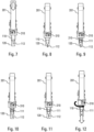
- FIG. 1 shows the three separate modules and the figures 2 to 12 show the assembly of the full tank module, the actuation of the motor module and the extraction of the empty tank module after actuation.
- the reservoir module 100 comprises a reservoir 110 which contains fluid product to be injected, a piston 111 and a needle 112.
- the piston 111 is adapted to move in said reservoir 110 to inject the fluid product through said needle 112.
- the term “reservoir” in the present description includes any type of container associated with a needle, such as a syringe or cartridge. Needle 112 may be permanently attached to said reservoir 110, or alternatively, needle 112 may be assembled on reservoir 110 prior to actuation of the autoinjector.
- the reservoir 110 is a cartridge, preferably made of glass.
- the reservoir module 100 has as few parts as possible, because it is disposable, and preferably no spring or other metal part.
- the reservoir module 100 advantageously comprises an actuator sleeve 120 whose axial end surface is in contact with the site to be injected and includes an opening allowing the passage of the needle 112 during the tapping phase. After actuation, the actuator sleeve 120 preferably covers the needle 112 of the reservoir to avoid any risk of pricking with said needle.
- the actuator sleeve 120 is adapted to slide relative to said reservoir 110 between an deployed position, in which it is disposed around said needle 112 and an actuated position, in which it is moved axially relative to the reservoir 110 to expose the needle 112 .
- the reservoir module 100 may include a needle protection cap 130 which can be removed before use of the autoinjector, advantageously by means of a suitable removal member 135.
- the engine module 200 contains the injection means and is preferably reusable. To be activated, it can be associated with the interface module 300 because the injection is advantageously triggered by it. This motor module 200 makes it possible to vary in a predetermined manner the actuation force Fa exerted on the piston rod during the injection phase, as will be explained in more detail below.
- the motor module 200 comprises a body 201, which is advantageously formed of two hollow shells fixed to one another.
- This body contains a piston rod 210 which, upon actuation, will come into contact with the piston 111 of the reservoir 110 and move it axially in the reservoir 110 to inject the fluid product.
- This piston rod 210 is advantageously guided axially in an appropriate guide profile of the body 201, such as for example a rail, a groove or a centering piece crossed by said piston rod 210.
- the body 201 of the engine module 200 also contains the injection and reset means which will be described in more detail below.
- the interface module 300 makes it possible to connect the motor module 200 to the tank module 100. It is also preferably reusable. This interface module 300 allows on the one hand the insertion of the reservoir module 100. When the reservoir 110 is a cartridge, as in the examples in the figures, the interface module 300 also allows the screwing of the needle sub-assembly and the extraction of the needle protection cap 130. Advantageously, this screwing and/or extraction of the cap is (are) possible only when the reservoir module 100 is assembled on the interface module 300. The latter also allows the movement of the actuator sleeve 120 at the start of actuation to perform the stitching and trigger the injection phase, and its locking in the safety position of the needle after the injection. Finally, it also allows the extraction of the empty tank module 100 to be replaced by a new full tank module 100.
- the interface module 300 advantageously comprises a selection ring 310 rotatably mounted relative to the motor module 200 and pivoting elements 320.
- the interface module 300 is assembled on the motor module 200.
- the selection ring 310 is in the locking position, in which insertion of the tank module 100 is possible and actuation of the motor module 200 is impossible.
- the user can insert an unused tank module 100 into the interface module 300, as illustrated in the figures 2 and 3 .
- a used tank module for example thanks to a keying system.
- an audible click is heard.
- the needle sub-assembly can first be assembled on the tank module, preferably after the assembly of said tank module 100 on the interface module 300.
- the selection ring 310 can then be unlocked towards an injection position, advantageously via rotation exerted by the user, as illustrated in the Figure 6 .
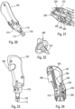
- THE figures 13 to 15 illustrate the assembly of the tank module 100 on the interface module 300.
- the pivoting elements 320 of the interface module 300 advantageously allow the tank module 100 to be locked on the interface module 300.
- the user presses the autoinjector on the site to be injected, which causes the axial sliding of the actuator sleeve 120 in the reservoir module 100, thus causing the needle 112 to pierce said site to be injected.
- the user must press with a force greater than a predeterminable threshold formed by a hard point provided to prevent any accidental sliding of said actuator sleeve 120.
- the selection ring 310 automatically turns to a safety position indicating that the reservoir module 100 will go into needle safety after the injection when the actuator sleeve 120 is deployed.
- the actuator sleeve 120 cooperates with the lock of the motor module to trigger the injection phase, and the fluid product contained in the reservoir 110 is expelled by the piston 111 pushed by the piston rod 210 which is controlled in force by an actuating spring 220.
- the user releases the pressure of the autoinjector on the skin, and the actuator sleeve 120 deploys and locks in the safety position.
- the user can then reset the motor module 200, as will be described in more detail below.
- the user turns the selection ring 310 to the “eject” position, and the reservoir module 110 is unlocked and translated axially by a few millimeters. The user then finishes manually removing the tank module 100 used.
- the selection ring 310 When released, the selection ring 310 automatically returns to the initial locked position, and it can then no longer be moved before assembling a new full tank module 100 in the interface module 300.
- the piston rod 210 is connected by a wire or belt 230 (or the like) to a toothed winding wheel 240, advantageously via a return wheel 250 forming a pulley.
- the injection spring 220 exerts an actuation force Fa on the piston rod 210, which is transmitted to the winding wheel 240 by said wire 230.
- a locking member 260 cooperates with the teeth 241 of said toothed winding wheel 240, said locking member 260 being movable, in particular pivoting, between a blocking position, visible on the Figure 17 , and an actuation position, visible on the Figure 19 .
- the locking member 260 in the blocking position, cooperates with a tooth 241 of the winding wheel 240 with two contact points C1 and C2 arranged on two non-parallel surfaces 242 and 243, as visible on the Figure 18 .
- This therefore generates two differently oriented forces F1 and F2.
- the locking member 260 comprises an extension 265, adapted to cooperate with the actuator sleeve 120 when the latter reaches its actuation position, that is to say once the needle 112 has pierced the site to be injected .
- an intermediate ring 270 is provided between the actuator sleeve 120 and the locking member 260.
- the actuator sleeve 120 pushes on said intermediate ring 270 with an unlocking force Fd, and said intermediate ring 270 transmits this force Fd to said extension 265 of the locking member 260, which causes the latter to pivot towards its actuation position.
- Winding wheel 240 is then no longer blocked in rotation, and the injection spring 220 can move the piston rod 210 to carry out the injection phase.
- the intermediate ring 270 is advantageously biased elastically into contact with the actuator sleeve 120, for example by a spring 275, so that the actuator sleeve 120 is biased towards its safety position after the injection.
- This lock geometry makes it possible to control the effort necessary for the user to unlock the lock and therefore trigger the injection. In particular, it guarantees a minimum effort for the user in order to unlock a large injection effort.
- an unlocking force Fd of 5N may be sufficient to unlock an injection spring 220 capable of exerting an actuation force Fa of approximately 100N on the piston rod 210.
- the lock forms an “engaging” system, meaning that the orientation of the forces allows for a self-locking system.
- an increase in the actuation force Fa has the effect of strengthening the locking of the lock.
- the device advantageously comprises force control means, in order to vary in a predetermined manner the force exerted by the injection spring 220 on the piston 111 of the reservoir 110 throughout the injection phase.
- a lever 280 which can be connected to the piston rod 210, to the injection spring 220 and to a cam 290, preferably integral with the body 201 of the engine module 200.
- cam is formed on the lever and that it cooperates with a fixed point secured to the body.
- the injection spring 220 can therefore be fixed on one side to the body 201 and on the other side to said lever 280, one end of which pivots on the piston rod 210 and the other end of which moves along said cam 290.
- the lever 280 therefore advantageously performs both a rotation around a point of the piston rod 210 and a translation movement relative to the body 201, these two movements being linked and carried out in the same plane.
- Each section corresponds to a specific shape of the cam 290, and it is therefore possible to predetermine any force profile by means of this cam 290.
- the user rearms the motor module 200 for future use with another tank module 100.
- the user rewinds the wire or belt 230 around the winding wheel 240.
- This returns the piston rod 210 to its starting position, before actuation, and recharges the injection spring 220.
- the user therefore rotates the winding wheel 240 in the opposite direction relative to the injection phase.
- the winding wheel 240 has several teeth 241, which cooperate with the locking member 260 in the manner of an anti-return ratchet.
- the locking member 260 retracts and locks after the passage of each tooth 241.
- a higher number of teeth 241 facilitates the rearming of the motor module 200 by the user.
- a reset crank 400 is provided, an example of which is visible on the Figure 22 .
- This crank 400 can for example cooperate with the winding wheel 240 via ribs 410 fitting into corresponding grooves 245 of the winding wheel 240.
- a form of reset could be produced directly on the winding wheel 240, replacing the crank.
- the crank 400 could also be replaced by a handle having teeth adapted to cooperate with the winding wheel 240.
- a set of pinions (not shown) can be provided to increase the winding force and therefore make it easier for the user.
- a floating pinion can be provided cooperating on the one hand with the crank 400 and on the other hand with teeth of the winding wheel 240, said floating pinion being movable in an oblong hole in the body. This allows the floating pinion to drive the winding wheel 240 only when it turns in one direction of rotation, without hindering the injection phase when the winding wheel 240 turns in the other direction.
- the present invention applies to devices used in particular for the treatments of autoimmune diseases, for example of the rheumatoid arthritis type, multiple sclerosis, Crohn's disease, for treatments against cancer, for antiviral treatments, for example of the type hepatitis, for treatments against diabetes, for treatments against anemia or for treatment of crises, for example in the event of anaphylactic shock.
- autoimmune diseases for example of the rheumatoid arthritis type, multiple sclerosis, Crohn's disease
- cancer for antiviral treatments, for example of the type hepatitis
- treatments against diabetes for treatments against anemia or for treatment of crises, for example in the event of anaphylactic shock.
Landscapes
- Health & Medical Sciences (AREA)
- Vascular Medicine (AREA)
- Engineering & Computer Science (AREA)
- Anesthesiology (AREA)
- Biomedical Technology (AREA)
- Heart & Thoracic Surgery (AREA)
- Hematology (AREA)
- Life Sciences & Earth Sciences (AREA)
- Animal Behavior & Ethology (AREA)
- General Health & Medical Sciences (AREA)
- Public Health (AREA)
- Veterinary Medicine (AREA)
- Infusion, Injection, And Reservoir Apparatuses (AREA)
Claims (8)
- Autoinjektor, enthaltend:- ein Reservoirmodul (100), das ein ein Fluidprodukt enthaltendes Reservoir (110) und einen Kolben (111) enthält und eine Nadel (112) aufweist, wobei das Reservoirmodul (100) eine Betätigungshülse (120) umfasst, die bezüglich des Reservoirs (110) zwischen einer Ausfahrstellung, in der sie um die Nadel (112) herum angeordnet ist, und einer Betätigungsstellung, in der sie bezüglich des Reservoirs (110) axial verstellt ist, um die Nadel (112) freizugeben, verstellbar ist,- ein Antriebsmodul (200),- ein Schnittstellenmodul (300), welches das Antriebmoduls (200) mit dem Reservoirmodul (100) verbindet,- wobei das Antriebsmodul (200) umfasst:dadurch gekennzeichnet, dass der Autoinjektor eine Rückstellkurbel (400) umfasst, um den Draht (230) durch Drehen des Aufwickelrads (240) in der der Richtung der Injektionsphase entgegengesetzten Richtung wieder auf das Aufwickelrad (240) aufzuwickeln.- einen Körper (201),- eine Kolbenstange (210), die dazu ausgelegt ist, mit dem Kolben (111) des Reservoirs (110) zusammenzuwirken, wobei die Kolbenstange (210) zwischen einer Ruhestellung und einer Injektionsstellung verstellbar ist, in der die Kolbenstange (210) den Kolben (111) des Reservoirs (110) verstellt hat, um das Fluidprodukt durch die Nadel (112) hindurch zu injizieren,- eine Injektionsfeder (220), um die Kolbenstange (210) in Richtung ihrer Injektionsstellung zu beaufschlagen,- ein Schloss, das die Kolbenstange (210) in der Ruhestellung sichert, wobei das Schloss einen Draht (230), der auf der einen Seite mit der Kolbenstange (210) und auf der anderen Seite mit einem gezahnten Aufwickelrad (240) verbunden ist, und ein Verriegelungsorgan (260) umfasst, das mit einem Zahn (241) des gezahnten Aufwickelrads (240) zusammenwirkt, wobei das Verriegelungsorgan (260) zwischen einer Sicherungsstellung, in der es eine Drehung des Aufwickelrads (240) in Richtung der von der Injektionsfeder (220) auf die Kolbenstange (210) ausgeübten Betätigungskraft (Fa) verhindert, und einer Betätigungsstellung, in der die Drehung des Aufwickelrads (240) möglich ist, bewegbar, insbesondere schwenkbar ist, wobei das Verriegelungsorgan (260) eine Verlängerung (265) aufweist, die dazu ausgelegt ist, mit der Betätigungshülse (120) zusammenzuwirken, wenn diese ihre Betätigungsstellung erreicht hat,
- Autoinjektor nach Anspruch 1,
wobei das Reservoirmodul (100) eine ferner Betätigungshülse (120) umfasst, die bezüglich des Reservoirs (110) zwischen einer Ausfahrstellung, in der sie um die Nadel (112) herum angeordnet ist, und einer Betätigungsstellung, in der sie bezüglich des Reservoirs (110) axial verstellt ist, um die Nadel (112) freizugeben, verstellbar ist. - Autoinjektor nach Anspruch 1 oder 2,
ferner umfassend ein Schnittstellenmodul (300), das am Antriebsmodul (200) befestigt ist und vor jeder Betätigung ein Reservoirmodul (100) aufnimmt. - Autoinjektor nach Anspruch 3,
wobei das Schnittstellenmodul (300) einen Auswahlring (310), der drehbar an dem Antriebsmodul (200) gelagert ist, und Schwenkelemente (320) zum Befestigen des Reservoirmoduls (100) im Schnittstellenmodul (300) umfasst. - Autoinjektor nach Anspruch 4,
wobei der Auswahlring (310) drehbeweglich ist zwischen einer Verriegelungsstellung, in der das Einsetzen eines Reservoirmoduls (100) möglich und die Betätigung des Antriebsmoduls (200) nicht möglich ist, einer Injektionsstellung, in der die Betätigung des Antriebsmoduls (200) möglich ist, einer Sicherheitsstellung, in der eine Betätigungshülse (120) des Reservoirmoduls (100) in eine ausgefahrene Stellung um die Nadel (112) herum zurückkehrt, und einer Auswurfstellung, in der der Auswurf des benutzten Reservoirmoduls möglich ist. - Autoinjektor nach einem der vorhergehenden Ansprüche,
wobei das Antriebsmodul (200) Kraftsteuermittel (280, 290) umfasst, um die Kraft, die von der Injektionsfeder (220) auf die Kolbenstange (210) ausgeübt wird, während der gesamten Injektionsphase in vorbestimmter Weise zu variieren, wobei die Kraftsteuermittel einen Hebel (280) und eine Steuerkurve (290) umfassen, wobei der Hebel (280) auf der einen Seite schwenkbar an der Kolbenstange (210) gelagert und mit der Injektionsfeder (220) verbunden ist und auf der anderen Seite mit der Steuerkurve (290) zusammenwirkt. - Autoinjektor nach einem der vorhergehenden Ansprüche,
wobei zwischen der Kolbenstange (210) und dem Aufwickelrad (240) ein Umlenkrad (250) vorgesehen ist, das eine Laufrolle für den Draht (230) bildet. - Autoinjektor nach einem der vorhergehenden Ansprüche,
wobei das Verriegelungsorgan (260) eine Verlängerung (265) aufweist, die dazu ausgelegt ist, mit einer Betätigungshülse (120) des Reservoirmoduls (100) zusammenzuwirken, wenn die Nadel (112) in die Injektionsstelle eingestochen ist, um das Verriegelungsorgan (260) in seine Betätigungsstellung zu verstellen.
Applications Claiming Priority (2)
| Application Number | Priority Date | Filing Date | Title |
|---|---|---|---|
| FR1858539A FR3086176B1 (fr) | 2018-09-20 | 2018-09-20 | Autoinjecteur. |
| PCT/FR2019/052194 WO2020058640A1 (fr) | 2018-09-20 | 2019-09-19 | Autoinjecteur. |
Publications (2)
| Publication Number | Publication Date |
|---|---|
| EP3852844A1 EP3852844A1 (de) | 2021-07-28 |
| EP3852844B1 true EP3852844B1 (de) | 2024-07-31 |
Family
ID=65201558
Family Applications (1)
| Application Number | Title | Priority Date | Filing Date |
|---|---|---|---|
| EP19795254.2A Active EP3852844B1 (de) | 2018-09-20 | 2019-09-19 | Automatischer injektor |
Country Status (5)
| Country | Link |
|---|---|
| US (1) | US12551627B2 (de) |
| EP (1) | EP3852844B1 (de) |
| CN (1) | CN112739399A (de) |
| FR (1) | FR3086176B1 (de) |
| WO (1) | WO2020058640A1 (de) |
Family Cites Families (16)
| Publication number | Priority date | Publication date | Assignee | Title |
|---|---|---|---|---|
| SE9901736D0 (sv) * | 1999-05-12 | 1999-05-12 | Pharmacia & Upjohn Ab | Injectino device and method for ITS operation |
| DE10240165A1 (de) * | 2002-08-30 | 2004-03-18 | Disetronic Licensing Ag | Vorrichtung zum dosierten Ausstoßen eines flüssigen Wirkstoffes und Infusionspumpe |
| DE10320225A1 (de) * | 2003-05-05 | 2004-12-02 | L + N Plast-Vertriebs Gmbh | Mehrweg-Betätigungsvorrichtung für eine sterile Spritze |
| GB0802351D0 (en) * | 2008-02-08 | 2008-03-12 | Owen Mumford Ltd | Injection devices |
| CA2757136A1 (en) * | 2009-03-31 | 2010-10-07 | Sanofi-Aventis Deutschland Gmbh | Improvements in and relating to a medicament delivery devices |
| EP2300078B1 (de) * | 2009-05-07 | 2016-03-23 | Medical Injection Devices Inc. | Medikamentenausgabevorrichtung |
| EP2438946A1 (de) * | 2010-10-08 | 2012-04-11 | Sanofi-Aventis Deutschland GmbH | Automatischer Injektor |
| US10022506B2 (en) * | 2012-04-11 | 2018-07-17 | Thomas Jefferson University | Hypodermic injection device incorporated in a case for a portable electronic device |
| MX352388B (es) * | 2012-08-29 | 2017-11-22 | Unitract Syringe Pty Ltd | Mecanismos impulsores de administración controlada de velocidad variable para bombas de administración de fármacos. |
| US8652100B1 (en) * | 2013-03-08 | 2014-02-18 | Teva Pharmaceutical Industries, Ltd. | Re-useable injector device for syringe |
| FR3007989B1 (fr) * | 2013-07-05 | 2016-01-01 | Aptar France Sas | Autoinjecteur. |
| EP3092019B1 (de) * | 2014-01-06 | 2018-07-18 | Novo Nordisk A/S | Schutzmechanismus für eine injektionsvorrichtung |
| FR3036965B1 (fr) * | 2015-06-05 | 2021-10-01 | Aptar France Sas | Autoinjecteur |
| FR3036967B1 (fr) * | 2015-06-05 | 2021-10-01 | Aptar France Sas | Autoinjecteur |
| US11179523B2 (en) * | 2017-01-20 | 2021-11-23 | Biogen Ma, Inc. | Smart injector |
| FR3086177B1 (fr) * | 2018-09-20 | 2022-11-04 | Aptar France Sas | Autoinjecteur. |
-
2018
- 2018-09-20 FR FR1858539A patent/FR3086176B1/fr active Active
-
2019
- 2019-09-19 WO PCT/FR2019/052194 patent/WO2020058640A1/fr not_active Ceased
- 2019-09-19 US US17/277,376 patent/US12551627B2/en active Active
- 2019-09-19 CN CN201980062227.XA patent/CN112739399A/zh active Pending
- 2019-09-19 EP EP19795254.2A patent/EP3852844B1/de active Active
Also Published As
| Publication number | Publication date |
|---|---|
| FR3086176B1 (fr) | 2022-11-04 |
| US20220031951A1 (en) | 2022-02-03 |
| FR3086176A1 (fr) | 2020-03-27 |
| EP3852844A1 (de) | 2021-07-28 |
| WO2020058640A1 (fr) | 2020-03-26 |
| US12551627B2 (en) | 2026-02-17 |
| CN112739399A (zh) | 2021-04-30 |
Similar Documents
| Publication | Publication Date | Title |
|---|---|---|
| EP3852845B1 (de) | Autoinjektor | |
| EP4208297B1 (de) | Vorrichtung zur abgabe eines flüssigen produkts | |
| EP1053037B1 (de) | Vorrichtung zur automatischen injektion einer dosis eines medikamentenprodukts | |
| EP2854905B1 (de) | Autoinjektor | |
| EP3302647B1 (de) | Automatischer injektor mit einem verzögerungssystem | |
| EP0825883A1 (de) | Wiederaufladbarer auto-injektor | |
| EP2854899B1 (de) | Autoinjektor | |
| EP2900299B1 (de) | Autoinjektor | |
| EP1682207A2 (de) | Geschützte injektionsspritzenvorrichtung | |
| EP3374008B1 (de) | Autoinjektor | |
| EP2854904B1 (de) | Autoinjektor | |
| EP2854901B1 (de) | Autoinjektor mit einer zeitverzögerungsvorrichtung mit planetengetriebe zur verzögerung des nadeleinzugs | |
| WO2017051113A1 (fr) | Autoinjecteur | |
| EP3302644A1 (de) | Automatischer injektor | |
| EP3374006B1 (de) | Autoinjektor mit einem mittelfenster mit einem dreieckigen ende | |
| EP3852844A1 (de) | Automatischer injektor | |
| FR2990865A1 (fr) | Autoinjecteur | |
| EP3302646B1 (de) | Autoinjektor mit einer verzögerungsvorrichtung mit einem planetengetriebe | |
| EP3831431A1 (de) | Vorrichtung für die einspritzung eines flüssigen produkts | |
| FR2990863A1 (fr) | Autoinjecteur | |
| FR2990867A1 (fr) | Autoinjecteur | |
| FR2990862A1 (fr) | Autoinjecteur | |
| FR2990864A1 (fr) | Autoinjecteur | |
| FR2995790A1 (fr) | Autoinjecteur |
Legal Events
| Date | Code | Title | Description |
|---|---|---|---|
| STAA | Information on the status of an ep patent application or granted ep patent |
Free format text: STATUS: UNKNOWN |
|
| STAA | Information on the status of an ep patent application or granted ep patent |
Free format text: STATUS: THE INTERNATIONAL PUBLICATION HAS BEEN MADE |
|
| PUAI | Public reference made under article 153(3) epc to a published international application that has entered the european phase |
Free format text: ORIGINAL CODE: 0009012 |
|
| STAA | Information on the status of an ep patent application or granted ep patent |
Free format text: STATUS: REQUEST FOR EXAMINATION WAS MADE |
|
| 17P | Request for examination filed |
Effective date: 20210415 |
|
| AK | Designated contracting states |
Kind code of ref document: A1 Designated state(s): AL AT BE BG CH CY CZ DE DK EE ES FI FR GB GR HR HU IE IS IT LI LT LU LV MC MK MT NL NO PL PT RO RS SE SI SK SM TR |
|
| DAV | Request for validation of the european patent (deleted) | ||
| DAX | Request for extension of the european patent (deleted) | ||
| STAA | Information on the status of an ep patent application or granted ep patent |
Free format text: STATUS: EXAMINATION IS IN PROGRESS |
|
| 17Q | First examination report despatched |
Effective date: 20220125 |
|
| GRAP | Despatch of communication of intention to grant a patent |
Free format text: ORIGINAL CODE: EPIDOSNIGR1 |
|
| STAA | Information on the status of an ep patent application or granted ep patent |
Free format text: STATUS: GRANT OF PATENT IS INTENDED |
|
| INTG | Intention to grant announced |
Effective date: 20240122 |
|
| P01 | Opt-out of the competence of the unified patent court (upc) registered |
Effective date: 20240325 |
|
| GRAJ | Information related to disapproval of communication of intention to grant by the applicant or resumption of examination proceedings by the epo deleted |
Free format text: ORIGINAL CODE: EPIDOSDIGR1 |
|
| STAA | Information on the status of an ep patent application or granted ep patent |
Free format text: STATUS: EXAMINATION IS IN PROGRESS |
|
| GRAJ | Information related to disapproval of communication of intention to grant by the applicant or resumption of examination proceedings by the epo deleted |
Free format text: ORIGINAL CODE: EPIDOSDIGR1 |
|
| GRAL | Information related to payment of fee for publishing/printing deleted |
Free format text: ORIGINAL CODE: EPIDOSDIGR3 |
|
| GRAS | Grant fee paid |
Free format text: ORIGINAL CODE: EPIDOSNIGR3 |
|
| GRAP | Despatch of communication of intention to grant a patent |
Free format text: ORIGINAL CODE: EPIDOSNIGR1 |
|
| STAA | Information on the status of an ep patent application or granted ep patent |
Free format text: STATUS: GRANT OF PATENT IS INTENDED |
|
| INTC | Intention to grant announced (deleted) | ||
| GRAA | (expected) grant |
Free format text: ORIGINAL CODE: 0009210 |
|
| STAA | Information on the status of an ep patent application or granted ep patent |
Free format text: STATUS: THE PATENT HAS BEEN GRANTED |
|
| INTG | Intention to grant announced |
Effective date: 20240621 |
|
| AK | Designated contracting states |
Kind code of ref document: B1 Designated state(s): AL AT BE BG CH CY CZ DE DK EE ES FI FR GB GR HR HU IE IS IT LI LT LU LV MC MK MT NL NO PL PT RO RS SE SI SK SM TR |
|
| REG | Reference to a national code |
Ref country code: CH Ref legal event code: EP Ref country code: GB Ref legal event code: FG4D Free format text: NOT ENGLISH |
|
| REG | Reference to a national code |
Ref country code: DE Ref legal event code: R096 Ref document number: 602019056184 Country of ref document: DE |
|
| REG | Reference to a national code |
Ref country code: IE Ref legal event code: FG4D Free format text: LANGUAGE OF EP DOCUMENT: FRENCH |
|
| REG | Reference to a national code |
Ref country code: LT Ref legal event code: MG9D |
|
| REG | Reference to a national code |
Ref country code: NL Ref legal event code: MP Effective date: 20240731 |
|
| PG25 | Lapsed in a contracting state [announced via postgrant information from national office to epo] |
Ref country code: PT Free format text: LAPSE BECAUSE OF FAILURE TO SUBMIT A TRANSLATION OF THE DESCRIPTION OR TO PAY THE FEE WITHIN THE PRESCRIBED TIME-LIMIT Effective date: 20241202 |
|
| REG | Reference to a national code |
Ref country code: AT Ref legal event code: MK05 Ref document number: 1707889 Country of ref document: AT Kind code of ref document: T Effective date: 20240731 |
|
| PG25 | Lapsed in a contracting state [announced via postgrant information from national office to epo] |
Ref country code: PT Free format text: LAPSE BECAUSE OF FAILURE TO SUBMIT A TRANSLATION OF THE DESCRIPTION OR TO PAY THE FEE WITHIN THE PRESCRIBED TIME-LIMIT Effective date: 20241202 |
|
| PG25 | Lapsed in a contracting state [announced via postgrant information from national office to epo] |
Ref country code: NO Free format text: LAPSE BECAUSE OF FAILURE TO SUBMIT A TRANSLATION OF THE DESCRIPTION OR TO PAY THE FEE WITHIN THE PRESCRIBED TIME-LIMIT Effective date: 20241031 |
|
| PG25 | Lapsed in a contracting state [announced via postgrant information from national office to epo] |
Ref country code: FI Free format text: LAPSE BECAUSE OF FAILURE TO SUBMIT A TRANSLATION OF THE DESCRIPTION OR TO PAY THE FEE WITHIN THE PRESCRIBED TIME-LIMIT Effective date: 20240731 Ref country code: NL Free format text: LAPSE BECAUSE OF FAILURE TO SUBMIT A TRANSLATION OF THE DESCRIPTION OR TO PAY THE FEE WITHIN THE PRESCRIBED TIME-LIMIT Effective date: 20240731 Ref country code: GR Free format text: LAPSE BECAUSE OF FAILURE TO SUBMIT A TRANSLATION OF THE DESCRIPTION OR TO PAY THE FEE WITHIN THE PRESCRIBED TIME-LIMIT Effective date: 20241101 Ref country code: PL Free format text: LAPSE BECAUSE OF FAILURE TO SUBMIT A TRANSLATION OF THE DESCRIPTION OR TO PAY THE FEE WITHIN THE PRESCRIBED TIME-LIMIT Effective date: 20240731 |
|
| PG25 | Lapsed in a contracting state [announced via postgrant information from national office to epo] |
Ref country code: BG Free format text: LAPSE BECAUSE OF FAILURE TO SUBMIT A TRANSLATION OF THE DESCRIPTION OR TO PAY THE FEE WITHIN THE PRESCRIBED TIME-LIMIT Effective date: 20240731 |
|
| PG25 | Lapsed in a contracting state [announced via postgrant information from national office to epo] |
Ref country code: LV Free format text: LAPSE BECAUSE OF FAILURE TO SUBMIT A TRANSLATION OF THE DESCRIPTION OR TO PAY THE FEE WITHIN THE PRESCRIBED TIME-LIMIT Effective date: 20240731 |
|
| PG25 | Lapsed in a contracting state [announced via postgrant information from national office to epo] |
Ref country code: AT Free format text: LAPSE BECAUSE OF FAILURE TO SUBMIT A TRANSLATION OF THE DESCRIPTION OR TO PAY THE FEE WITHIN THE PRESCRIBED TIME-LIMIT Effective date: 20240731 Ref country code: IS Free format text: LAPSE BECAUSE OF FAILURE TO SUBMIT A TRANSLATION OF THE DESCRIPTION OR TO PAY THE FEE WITHIN THE PRESCRIBED TIME-LIMIT Effective date: 20241130 |
|
| PG25 | Lapsed in a contracting state [announced via postgrant information from national office to epo] |
Ref country code: HR Free format text: LAPSE BECAUSE OF FAILURE TO SUBMIT A TRANSLATION OF THE DESCRIPTION OR TO PAY THE FEE WITHIN THE PRESCRIBED TIME-LIMIT Effective date: 20240731 |
|
| PG25 | Lapsed in a contracting state [announced via postgrant information from national office to epo] |
Ref country code: RS Free format text: LAPSE BECAUSE OF FAILURE TO SUBMIT A TRANSLATION OF THE DESCRIPTION OR TO PAY THE FEE WITHIN THE PRESCRIBED TIME-LIMIT Effective date: 20241031 Ref country code: ES Free format text: LAPSE BECAUSE OF FAILURE TO SUBMIT A TRANSLATION OF THE DESCRIPTION OR TO PAY THE FEE WITHIN THE PRESCRIBED TIME-LIMIT Effective date: 20240731 |
|
| PG25 | Lapsed in a contracting state [announced via postgrant information from national office to epo] |
Ref country code: RS Free format text: LAPSE BECAUSE OF FAILURE TO SUBMIT A TRANSLATION OF THE DESCRIPTION OR TO PAY THE FEE WITHIN THE PRESCRIBED TIME-LIMIT Effective date: 20241031 Ref country code: PL Free format text: LAPSE BECAUSE OF FAILURE TO SUBMIT A TRANSLATION OF THE DESCRIPTION OR TO PAY THE FEE WITHIN THE PRESCRIBED TIME-LIMIT Effective date: 20240731 Ref country code: NO Free format text: LAPSE BECAUSE OF FAILURE TO SUBMIT A TRANSLATION OF THE DESCRIPTION OR TO PAY THE FEE WITHIN THE PRESCRIBED TIME-LIMIT Effective date: 20241031 Ref country code: NL Free format text: LAPSE BECAUSE OF FAILURE TO SUBMIT A TRANSLATION OF THE DESCRIPTION OR TO PAY THE FEE WITHIN THE PRESCRIBED TIME-LIMIT Effective date: 20240731 Ref country code: LV Free format text: LAPSE BECAUSE OF FAILURE TO SUBMIT A TRANSLATION OF THE DESCRIPTION OR TO PAY THE FEE WITHIN THE PRESCRIBED TIME-LIMIT Effective date: 20240731 Ref country code: IS Free format text: LAPSE BECAUSE OF FAILURE TO SUBMIT A TRANSLATION OF THE DESCRIPTION OR TO PAY THE FEE WITHIN THE PRESCRIBED TIME-LIMIT Effective date: 20241130 Ref country code: HR Free format text: LAPSE BECAUSE OF FAILURE TO SUBMIT A TRANSLATION OF THE DESCRIPTION OR TO PAY THE FEE WITHIN THE PRESCRIBED TIME-LIMIT Effective date: 20240731 Ref country code: GR Free format text: LAPSE BECAUSE OF FAILURE TO SUBMIT A TRANSLATION OF THE DESCRIPTION OR TO PAY THE FEE WITHIN THE PRESCRIBED TIME-LIMIT Effective date: 20241101 Ref country code: FI Free format text: LAPSE BECAUSE OF FAILURE TO SUBMIT A TRANSLATION OF THE DESCRIPTION OR TO PAY THE FEE WITHIN THE PRESCRIBED TIME-LIMIT Effective date: 20240731 Ref country code: ES Free format text: LAPSE BECAUSE OF FAILURE TO SUBMIT A TRANSLATION OF THE DESCRIPTION OR TO PAY THE FEE WITHIN THE PRESCRIBED TIME-LIMIT Effective date: 20240731 Ref country code: BG Free format text: LAPSE BECAUSE OF FAILURE TO SUBMIT A TRANSLATION OF THE DESCRIPTION OR TO PAY THE FEE WITHIN THE PRESCRIBED TIME-LIMIT Effective date: 20240731 Ref country code: AT Free format text: LAPSE BECAUSE OF FAILURE TO SUBMIT A TRANSLATION OF THE DESCRIPTION OR TO PAY THE FEE WITHIN THE PRESCRIBED TIME-LIMIT Effective date: 20240731 |
|
| PG25 | Lapsed in a contracting state [announced via postgrant information from national office to epo] |
Ref country code: SM Free format text: LAPSE BECAUSE OF FAILURE TO SUBMIT A TRANSLATION OF THE DESCRIPTION OR TO PAY THE FEE WITHIN THE PRESCRIBED TIME-LIMIT Effective date: 20240731 Ref country code: RO Free format text: LAPSE BECAUSE OF FAILURE TO SUBMIT A TRANSLATION OF THE DESCRIPTION OR TO PAY THE FEE WITHIN THE PRESCRIBED TIME-LIMIT Effective date: 20240731 Ref country code: DK Free format text: LAPSE BECAUSE OF FAILURE TO SUBMIT A TRANSLATION OF THE DESCRIPTION OR TO PAY THE FEE WITHIN THE PRESCRIBED TIME-LIMIT Effective date: 20240731 |
|
| PG25 | Lapsed in a contracting state [announced via postgrant information from national office to epo] |
Ref country code: MC Free format text: LAPSE BECAUSE OF FAILURE TO SUBMIT A TRANSLATION OF THE DESCRIPTION OR TO PAY THE FEE WITHIN THE PRESCRIBED TIME-LIMIT Effective date: 20240731 Ref country code: EE Free format text: LAPSE BECAUSE OF FAILURE TO SUBMIT A TRANSLATION OF THE DESCRIPTION OR TO PAY THE FEE WITHIN THE PRESCRIBED TIME-LIMIT Effective date: 20240731 |
|
| PG25 | Lapsed in a contracting state [announced via postgrant information from national office to epo] |
Ref country code: CZ Free format text: LAPSE BECAUSE OF FAILURE TO SUBMIT A TRANSLATION OF THE DESCRIPTION OR TO PAY THE FEE WITHIN THE PRESCRIBED TIME-LIMIT Effective date: 20240731 |
|
| PG25 | Lapsed in a contracting state [announced via postgrant information from national office to epo] |
Ref country code: SK Free format text: LAPSE BECAUSE OF FAILURE TO SUBMIT A TRANSLATION OF THE DESCRIPTION OR TO PAY THE FEE WITHIN THE PRESCRIBED TIME-LIMIT Effective date: 20240731 |
|
| REG | Reference to a national code |
Ref country code: CH Ref legal event code: PL |
|
| REG | Reference to a national code |
Ref country code: DE Ref legal event code: R097 Ref document number: 602019056184 Country of ref document: DE |
|
| PG25 | Lapsed in a contracting state [announced via postgrant information from national office to epo] |
Ref country code: LU Free format text: LAPSE BECAUSE OF NON-PAYMENT OF DUE FEES Effective date: 20240919 |
|
| PLBE | No opposition filed within time limit |
Free format text: ORIGINAL CODE: 0009261 |
|
| STAA | Information on the status of an ep patent application or granted ep patent |
Free format text: STATUS: NO OPPOSITION FILED WITHIN TIME LIMIT |
|
| 26N | No opposition filed |
Effective date: 20250501 |
|
| REG | Reference to a national code |
Ref country code: BE Ref legal event code: MM Effective date: 20240930 |
|
| PG25 | Lapsed in a contracting state [announced via postgrant information from national office to epo] |
Ref country code: BE Free format text: LAPSE BECAUSE OF NON-PAYMENT OF DUE FEES Effective date: 20240930 |
|
| PG25 | Lapsed in a contracting state [announced via postgrant information from national office to epo] |
Ref country code: CH Free format text: LAPSE BECAUSE OF NON-PAYMENT OF DUE FEES Effective date: 20240930 |
|
| PG25 | Lapsed in a contracting state [announced via postgrant information from national office to epo] |
Ref country code: IE Free format text: LAPSE BECAUSE OF NON-PAYMENT OF DUE FEES Effective date: 20240919 |
|
| PG25 | Lapsed in a contracting state [announced via postgrant information from national office to epo] |
Ref country code: SE Free format text: LAPSE BECAUSE OF FAILURE TO SUBMIT A TRANSLATION OF THE DESCRIPTION OR TO PAY THE FEE WITHIN THE PRESCRIBED TIME-LIMIT Effective date: 20240731 |
|
| PGFP | Annual fee paid to national office [announced via postgrant information from national office to epo] |
Ref country code: DE Payment date: 20250916 Year of fee payment: 7 |
|
| PGFP | Annual fee paid to national office [announced via postgrant information from national office to epo] |
Ref country code: IT Payment date: 20250909 Year of fee payment: 7 |
|
| PGFP | Annual fee paid to national office [announced via postgrant information from national office to epo] |
Ref country code: GB Payment date: 20250919 Year of fee payment: 7 |
|
| PGFP | Annual fee paid to national office [announced via postgrant information from national office to epo] |
Ref country code: FR Payment date: 20250929 Year of fee payment: 7 |
|
| PG25 | Lapsed in a contracting state [announced via postgrant information from national office to epo] |
Ref country code: CY Free format text: LAPSE BECAUSE OF FAILURE TO SUBMIT A TRANSLATION OF THE DESCRIPTION OR TO PAY THE FEE WITHIN THE PRESCRIBED TIME-LIMIT; INVALID AB INITIO Effective date: 20190919 |
|
| PG25 | Lapsed in a contracting state [announced via postgrant information from national office to epo] |
Ref country code: HU Free format text: LAPSE BECAUSE OF FAILURE TO SUBMIT A TRANSLATION OF THE DESCRIPTION OR TO PAY THE FEE WITHIN THE PRESCRIBED TIME-LIMIT; INVALID AB INITIO Effective date: 20190919 |