EP3852968B1 - Système d'alignement de portions de rail pour soudeuse à induction - Google Patents
Système d'alignement de portions de rail pour soudeuse à induction Download PDFInfo
- Publication number
- EP3852968B1 EP3852968B1 EP19780159.0A EP19780159A EP3852968B1 EP 3852968 B1 EP3852968 B1 EP 3852968B1 EP 19780159 A EP19780159 A EP 19780159A EP 3852968 B1 EP3852968 B1 EP 3852968B1
- Authority
- EP
- European Patent Office
- Prior art keywords
- rail
- clamping
- rail portion
- axis
- frame
- Prior art date
- Legal status (The legal status is an assumption and is not a legal conclusion. Google has not performed a legal analysis and makes no representation as to the accuracy of the status listed.)
- Active
Links
Images


Classifications
-
- B—PERFORMING OPERATIONS; TRANSPORTING
- B23—MACHINE TOOLS; METAL-WORKING NOT OTHERWISE PROVIDED FOR
- B23K—SOLDERING OR UNSOLDERING; WELDING; CLADDING OR PLATING BY SOLDERING OR WELDING; CUTTING BY APPLYING HEAT LOCALLY, e.g. FLAME CUTTING; WORKING BY LASER BEAM
- B23K13/00—Welding by high-frequency current heating
- B23K13/01—Welding by high-frequency current heating by induction heating
- B23K13/015—Butt welding
-
- B—PERFORMING OPERATIONS; TRANSPORTING
- B23—MACHINE TOOLS; METAL-WORKING NOT OTHERWISE PROVIDED FOR
- B23K—SOLDERING OR UNSOLDERING; WELDING; CLADDING OR PLATING BY SOLDERING OR WELDING; CUTTING BY APPLYING HEAT LOCALLY, e.g. FLAME CUTTING; WORKING BY LASER BEAM
- B23K37/00—Auxiliary devices or processes, not specially adapted for a procedure covered by only one of the other main groups of this subclass
- B23K37/04—Auxiliary devices or processes, not specially adapted for a procedure covered by only one of the other main groups of this subclass for holding or positioning work
- B23K37/0426—Fixtures for other work
- B23K37/0435—Clamps
-
- E—FIXED CONSTRUCTIONS
- E01—CONSTRUCTION OF ROADS, RAILWAYS, OR BRIDGES
- E01B—PERMANENT WAY; PERMANENT-WAY TOOLS; MACHINES FOR MAKING RAILWAYS OF ALL KINDS
- E01B29/00—Laying, rebuilding, or taking-up tracks; Tools or machines therefor
- E01B29/42—Undetachably joining or fastening track components in or on the track, e.g. by welding, by gluing; Pre-assembling track components by gluing; Sealing joints with filling components
- E01B29/46—Devices for holding, positioning, or urging together the rail ends
-
- B—PERFORMING OPERATIONS; TRANSPORTING
- B23—MACHINE TOOLS; METAL-WORKING NOT OTHERWISE PROVIDED FOR
- B23K—SOLDERING OR UNSOLDERING; WELDING; CLADDING OR PLATING BY SOLDERING OR WELDING; CUTTING BY APPLYING HEAT LOCALLY, e.g. FLAME CUTTING; WORKING BY LASER BEAM
- B23K2101/00—Articles made by soldering, welding or cutting
- B23K2101/26—Railway- or like rails
Definitions
- the present invention relates to an alignment system and method for welding railway rails.
- the invention further relates generally to induction welding of railway rails.
- welders are used to weld sections of rail to create a continuous welded rail.
- the quality of the welding of the rail sections, also called the rail joint, is felt by passengers, particularly when a railway vehicle passes over it, where a poor weld results in a slight shock, for example. This is all the more important for railway tracks intended for high-speed rail vehicles, particularly given the risk of derailment.
- Welding can be carried out on the track, during track maintenance, or in the workshop, during the production of long welded rails (LRS), increasingly used in the laying of railway tracks in order to reduce the majority of rail joints over long lengths.
- LRS long welded rails
- a system commonly called a " rail puller” in English is used to bring two ends of two rail sections together and tension them.
- This type of system generally includes jacks connected to rotating clamping means connected to the ends of the jack.
- the actuation of the jacks allows each rail to be clamped while bringing them into contact with each other.
- the advantage of such a system is that it simultaneously performs clamping and tensioning, the force of the clamping means being multiplied by the connection of the clamping means to the jacks.
- a jack capable of exerting a force of 100 tonnes can lead to a clamping of more than 250 tonnes on each rail section.
- the use of a ruler by the operators ensures the correct alignment of the rail sections but proves to be imprecise in practice.
- the quality of the weld also depends on the welding technique used. Current welding methods have limitations in terms of health, environmental protection, and safety.
- Thermit ® type welding based on aluminothermy, consists of an exothermic reduction of a metal oxide (usually iron) by aluminum powder.
- a metal oxide usually iron
- the iron weld obtained remains more fragile than the body of the rail sections, preheating with a flame is dangerous for operators, the exothermic reaction of aluminothermy can be explosive in the event of contact with water.
- a system for use in welding one end of a first rail portion to one end of a second rail portion is known from document WO2010/015309 .
- the clamping means coupled to the biasing means make it possible to transmit a force to the rail portions so as to bring them together.
- the first and second frames, connected by the sliding means, carrying the clamping means are thus adapted to follow the movements of the biasing means, the latter transmitting to them the movement to which the rail portions are subjected.
- the first and second frames, the vertical positioning of which is fixed relative to the two rail portions to be welded, carry the means for aligning the rail portions, thus ensuring the correct alignment of the axes, along which the rail portions extend, with the longitudinal axis of the system.
- Such a system therefore makes it possible, once positioned above the two rail sections, to align the two rail sections, without additional intervention from the operators, to ensure the alignment of the rail sections during welding operations.
- connection of the clamping means with the stressing means also allows the system to ensure the clamping of the rail portions, by means of these stressing means, the latter also allowing the rail portions to be brought together with a view to welding them and bringing the ends of the rails into contact and stressing each other.
- each frame provides a positioning reference for the alignment modules but also for the possible welding module.
- the biasing means comprise a first linear actuator and a second linear actuator each connected to the first clamping means and to the second clamping means.
- the biasing means comprise first biasing means connected to the first clamping means and to the second clamping means and second biasing means connected to the first clamping means and to the second clamping means.
- the first biasing means may comprise at least the first linear actuator and the second biasing means may comprise at least the second linear actuator.
- the first biasing means and the second biasing means are arranged symmetrically to each other relative to a perpendicular plane containing the longitudinal axis of extension of the rail portions.
- linear actuators make it possible to transmit a longitudinal movement to the first and second frames, but also makes it possible to induce the clamping of the rail portions by the jaws simultaneously with the bringing together of the ends of the rail portions to be welded.
- the translational movement of the first and second linear actuators along the longitudinal axis induces the rotation of the pairs of jaws. constituting the first and second clamping means, respectively, on the first frame and the second frame.
- the jaws of the clamping means are thus connected to the first and second frame by means of a pivot connection, thus allowing the pairs of jaws, respectively consisting of the first and second jaws and the third and fourth jaws, to be moved into the clamping position and into the free position when the actuators are activated.
- the movement of the jaw pairs is coordinated, so that the clamping jaw pairs are placed in a clamping position or a free position simultaneously.
- the pivot connection of the jaws on the frame as described above, therefore allows the actuators to rotate the jaws relative to the first and second frames.
- first jaw and the second jaw are coupled in rotation with each other by means of first means for synchronizing the rotation speed of said jaws.
- the third jaw and the fourth jaw are coupled in rotation with each other by means of second means for synchronizing the rotation speed of said jaws.
- each jaw of the same clamping means i.e. supported by the same frame, is moved in rotation in an identical angular manner. This allows in particular, when clamping rail sections, that the same stress is applied on both sides of the rail.
- the jaws constituting a clamping means are then driven by a synchronous rotary movement when the jaws are moved between the clamping position and the free position.
- first and second jaws may be connected to a first clamping actuator configured to establish the free position and a pre-clamping position of the first clamping means.
- the third and fourth jaws may be connected to a second clamping actuator configured to establish the free position and a pre-clamping position of the second clamping means.
- first and second actuators By means of this connection between the first and second actuators and the first and second frames, the longitudinal forces of the actuators are also transmitted to the frames which then move longitudinally relative to each other as permitted by the slide. This therefore allows, during the alignment and bringing together of the two rail portions, that the first and second frames cooperate by sliding according to the reduction or increase of the longitudinal distance between the ends of the rail portions to be welded.
- the sliding connection can be achieved by means of a sliding device comprising at least two first longitudinal arms belonging to the first chassis and capable of sliding in at least two second longitudinal arms belonging to the second chassis.
- the sliding of the arms of the first chassis in the arms of the second chassis allows the first and second chassis to which the first and second actuators transmit longitudinal forces (oriented in the same direction), to bring the first and second frames closer or further apart along the longitudinal axis relative to each other.
- the first means for aligning the first axis of the first rail portion and the second means for aligning the second axis of the second rail portion may each comprise a module for lateral alignment of the axis of the rail portion in question with the longitudinal axis.
- first means for aligning the first axis of the first rail portion and the second means for aligning the second axis of the second rail portion may each comprise a module for vertically aligning the axis of the rail portion in question with the longitudinal axis.
- the system has means ensuring the alignment of the rail portions in the longitudinal plane and means ensuring that the upper surfaces of the heads of the rail portions are contained in a plane transverse to the longitudinal plane.
- each lateral alignment module may comprise hooking means capable of hooking the lower part of the head of the rail portion in question so as to laterally position the axis of the rail portion along the longitudinal axis.
- the hooking means may comprise a pair of jaws configured to simultaneously hook the rail in question on either side of the head.
- the jaws can each be pivotally articulated about an axis parallel to the longitudinal axis.
- each of the jaws of the same pair of jaws are symmetrical with respect to the longitudinal plane.
- the hooking means thus come on either side of the portion of rail to be aligned with the longitudinal axis, so as to ensure the lateral alignment of the portions of rail.
- the hooking means can be configured to move the portion of rail in question vertically upwards to a stop surface belonging to the vertical alignment module.
- the lateral alignment modules act in a complementary manner on the rail portions with the vertical alignment modules.
- the jaws of the hooking means vertically move the rail portions in contact with the stop surface of the vertical alignment module, ensuring alignment of the upper surfaces of the heads of the two rail portions to be welded.
- the system may include two vertical alignment modules arranged longitudinally on either side of the lateral alignment module.
- the present disclosure also relates to a railway rail welder comprising a system as described above, in which the system comprises a welding module or welding means, preferably by induction.
- a third chassis can carry the welding module, preferably by induction heating, this third chassis being slidably mounted on the first chassis along the longitudinal axis.
- the welder may comprise means for deburring the welding area of said ends of rail portions.
- the deburring means may be carried by a frame independent of the first and second frames, which may be mounted to slide along the longitudinal axis. In this way, it is possible to preserve the ends of the sections of rails in tension on each other after welding, until the end of the operation of joining the ends of sections of rails.
- the deburring means may be carried by the same chassis carrying the welding module.
- This chassis may be the third chassis.
- an induction welding module in combination with the system, ensures welding without misalignment of the rail sections along the longitudinal axis of the system, and therefore of better quality and with better mechanical resistance.
- Such a welder thus integrates all the modules necessary for welding sections of rail, the action of the operators being limited to positioning the welder above the sections of rail to be welded.
- Cooling means may be provided to limit the heating of system parts.
- the welder as presented here has a format, such that it can be transported and used on the track.
- FIG. 1 therefore illustrates an example of a welder 2 according to the invention, intended to weld a first portion of rail P1 and a second portion of rail P2 which can be used to constitute a rail of a railway track.
- the welder 2 comprises an external fairing 4, intended to protect the internal constituent elements of the welder 2, in particular from bad weather or impacts.
- the welder 2 further comprises a hooking member 6, composed of an opening 8 for the passage of a lifting member.
- This hooking member is connected to the frame of the welder which is formed of several chassis so as to be able to lift the welder 2 so as to be able to unload or load it from a vehicle for the installation of the welder on a railway track or the removal of the installation.
- the welder 2 comprises a system intended to be used for welding a first portion of rail P1 with a second portion of rail P2.
- FIG. 2A A perspective view of an example of a part 10 of this system is illustrated in Figure 2A .
- This part 10 of system allows the bringing together the two rail portions along a longitudinal axis A of the system.
- This system extends along a longitudinal axis A, corresponding to the x axis of the reference frame 12, and comprises a first 14 and a second 16 chassis.
- the first frame 14 and the second frame 16 are preferably of identical general H shape.
- the frames could also have a shape different from each other and/or different from an H shape. They comprise two parallel longitudinal supports 18a, 18b, 20a, 20b, extending parallel to the x axis, connected by one of their ends by a support 22, 24 extending perpendicular to the two longitudinal supports 18a, 18b, 20a, 20b, that is to say along the z axis.
- the first and second frames 14, 16 are connected by sliding connection means of the first frame with the second frame along the longitudinal axis A called the extension axis of said two rail portions along which the first axis, along which the first rail portion extends, and the second axis, along which the second rail portion extends, are intended to be aligned with each other and with the longitudinal axis.
- sliding connection means allowing the relative translation of the first and second frames 14, 16 along the longitudinal axis A, that is to say parallel to the axis x of the reference frame.
- the sliding connection is achieved by means of a slide device 26.
- These two longitudinal arms 28a, 28b are capable of sliding in at least two second longitudinal arms, integral and arranged in the continuity of the longitudinal supports 20a, 20b of the second frame 16 or directly in the longitudinal supports 20a, 20b of the first frame 14.
- the sliding connection can be reversed, that is to say that the second longitudinal arms of the second chassis 16 are able to slide into the first arms of the first chassis 14 or directly into the longitudinal supports 18a, 18b of the first chassis 14.
- the stroke of the second chassis 16 relative to the first chassis 14 or vice versa is approximately 750 mm.
- This assembly comprising the two frames 14, 16 constitutes the support on which different modules of the system and of the welder 2 according to the invention are mounted.
- system further comprises means for clamping the rail portions to be welded, so as to hold them in position, or to exert longitudinal forces in order to bring the ends of the rail portions together with a view to welding them.
- first clamping means 30 for clamping the first rail portion P1 are carried by the first frame 14. These clamping means 30 are configured to establish at least one free position in which the rail portion P1 is not clamped and is freely movable relative to said first clamping means and at least one clamping position for the first rail portion preventing any longitudinal translation of said rail portion P1.
- second clamping means 32 for clamping the second rail portion are carried by the second frame 16 and configured to establish at least one free position for the second rail portion P2 and at least one clamping position for the second rail portion P2.
- the first 30 and second 32 clamping means each comprise pairs of jaws.
- the first clamping means comprise a first jaw 34a and a second jaw 34b articulated in rotation on the first frame 14.
- the first 34a and second 34b jaws are movable in rotation around respectively a first vertical axis 34a1 and a second axis 34b1 vertical, the first axis 34a1 and the second axis 34b1 are parallel to the y axis of the reference frame.
- the first 34a1 and second 34b1 vertical axes are furthermore equidistant from the longitudinal axis A of the system 10 and located on either side of a vertical plane comprising the longitudinal axis A.
- the second clamping means 32 comprise a third jaw 36a and a fourth jaw 36b articulated in rotation on the second chassis 16 respectively around a third vertical axis 36a1 and fourth 36b1 vertical axis.
- the third 36a1 and fourth 36b1 vertical axes are also parallel and equidistant from the longitudinal axis of the system and located on either side of a vertical plane comprising the longitudinal axis A.
- the jaws 34a, 34b, 36a, 36b each comprise a contact portion 38 intended to be applied, that is to say to come into contact with the rail, in particular bearing on the web of the rail, when the clamping means are in the clamping position.
- This portion 38 comprises a hardened steel coating, the surface of which intended to bear on the web of the rail portion is gripped so as to better transmit the forces onto the rail portion on which it is applied.
- the clamping jaws 34a, 34b, 36a, 36b i.e. the first clamping means 30 and the second clamping means 32, are each connected to stressing means, here a first linear actuator 40 and a second linear actuator 42.
- stressing means here a first linear actuator 40 and a second linear actuator 42.
- These two actuators 40, 42 are arranged on either side of the longitudinal axis A of the system, and are equidistant from the longitudinal axis A and are located on either side of a vertical plane comprising the longitudinal axis A.
- an actuator is understood to mean a device that transforms the energy supplied to it into a physical phenomenon that provides work, modifies the behavior or state of a system.
- a pneumatic or hydraulic cylinder generates movement from mechanical energy transmitted by a gaseous or liquid fluid.
- one end of the piston 44 of the first cylinder 40 is connected to the first jaw 34a and the body 48 of the first cylinder 40 is connected to the third jaw 36a.
- One end of the piston 46 of the second cylinder 42 is connected to the second jaw 34b and the body 50 of the second second cylinder 42 is connected to the fourth jaw 36b.
- the jaws 34a, 34b, 36a, 36b of the first and second clamping means 30, 32, the first 34a, second 34b, third 36a and fourth jaws 36b are connected to the first cylinder 40 and to the second cylinder 42 so as to be articulated in rotation around respectively first 34a3, second 34b3, third 36a3 and fourth 36b3 vertical axes, these axes being parallel to each other, and equidistant two by two from the longitudinal axis A of the system and located on either side of a vertical plane comprising the longitudinal axis.
- the stroke of the pistons 44, 46 of the linear actuators 40, 42 is approximately 750 mm.
- these linear actuators 40, 42 are capable of exerting on the clamping jaws 34a, 34b, 36a, 36b a longitudinal force, that is to say oriented along the x axis of the reference frame.
- the actuation of the first and second stressing means, that is to say the first and second jacks 40, 42 induces a clamping of the first rail portion by the first clamping means 30, that is to say the first and second clamping jaws 34a, 34b and a clamping of the second rail portion by the second clamping means 32, that is to say the third and fourth clamping jaws 36a, 36b.
- actuators 40, 42 also make it possible to force the ends of the rail portions towards each other with a view to welding them. Indeed, once the clamping means are in the clamping position ( Figure 5 ) using the linear actuators 40, 42, the longitudinal force makes it possible to bring the ends of the rail portions closer together along the longitudinal axis A of the system while increasing the clamping force applied to each pair of jaws 34a, 34b and 36a, 36b.
- the actuators 40, 42 are also connected to the first frame 14 via the first clamping means 30 and to the second chassis 16 by means of the second clamping means 32.
- the longitudinal forces of the linear actuators 40, 42 are transmitted to said first and second chassis 14, 16, which, thanks to their sliding connection 26, follow the longitudinal movement of the pistons 44, 46 of the jacks 40, 42.
- the system also includes side actuators, also called clamp actuators 52, 54, as seen in the Figures 2A and 2B .
- the first and second clamping actuators 52, 54, of the jacks in the illustrated example, are respectively carried by the first and second jaws 34a, 34b and the third and fourth jaws 36a, 36b.
- These jacks 52, 54 whose connection point, more precisely the axis of rotation, with the jaws 34a, 34b, 36a, 36b is arranged, in the direction z of the reference frame, between the connection points with the linear actuator 40, 42 and the connection point with the chassis 14, 16, make it possible to position the clamping means 30, 32 in a so-called pre-clamping position, consisting of bringing the parts 38 intended to be in contact with the rail closer to the latter (and therefore to the longitudinal axis A). They are also configured to position the jaws 34a, 34b, 36a, 36b of the first and second clamping means 30, 32 in a free position, where the jaws 34a, 34b, 36a, 36b are separated by rotation of the longitudinal axis A.
- the connection between the clamping actuators 52, 54 and the jaws 34a, 34b, 36a, 36b allows rotation about the respective vertical axes 34a2, 34b2, 36a2, 36b2 so that activation of the clamping actuators 52, 54 allows rotation of the jaws 34a, 34b, 36a, 36b about their pivot connection 34a1, 34b1, 36a1, 36b1 with the frame 14, 16.
- the stroke of the pistons of clamping actuators 50, 52 is about 200 mm.
- the synchronization means 56, 60 comprise two parts comprising a rod, secured respectively to the first and second jaws 34a, 34b and a head 58 comprising teeth.
- Their rods are arranged in two bores passing through the first chassis 14, such that the heads 58 are arranged on the upper part of the chassis 14 along the z axis and the parts are movable in rotation inside the two bores.
- the heads 58 of the first synchronization means 56 are thus oriented so that the teeth of the first and second heads 58 mesh together.
- the first and second parts are driven in rotation.
- the meshing of the teeth of said first and second heads 58 makes it possible to constrain the rotation of these jaws 34a, 34b.
- their angular rotation speed is identical, when the first and second linear actuators 40, 42 are actuated and/or when the first lateral actuator 52 is actuated.
- the forces of the jaws 34a, 34b on the rails are distributed identically on either side thereof.
- identical second synchronization means 60 are used for the second clamping means 32, i.e. the third and fourth jaws 36a, 36b.
- the first and second jaws 34a, 34b and the third and fourth jaws 36a, 36b are coupled in rotation by means of the first speed synchronization means and the second speed synchronization means 56, 60 respectively.
- a central chassis called third chassis 62, is connected to the body of a first cylinder 64 and a second cylinder 66 allowing the third chassis 62 to be moved longitudinally.
- the rods of the first and second positioning cylinders of the third chassis are respectively the rods 44, 46 of the first linear actuator 40 and of the second linear actuator 42.
- the third frame 62 extends perpendicular to the lateral supports 18a, 18b, 20a, 20b of the first and second frames 14, 16, that is to say in the z direction of the reference frame.
- the stroke of the pistons of the actuators 64, 66 for positioning the third frame 62 is approximately 300 mm.
- the third chassis 62 carries the welding means, and can, by means of the first and second actuators 64, 66 for positioning the third chassis 62, be moved into a desired position along the longitudinal axis A.
- THE figures 3 to 5 illustrate different states of the part of the system allowing the bringing together of sections of rails.
- FIG. 3 illustrates a position of the part of the system where the linear actuators 40, 42 are activated, and that the pistons 44, 46 of these actuators 40, 42 are at the end of their travel, in a so-called extended position.
- FIG. 4 illustrates a position of the part of the system, where the first clamping actuator 52 is activated so as to position the first and second jaws 34a, 34b in a pre-clamping position.
- the parts 38 intended to be in contact with the rail are brought closer to each other and to the longitudinal axis A of the system.
- This rotation of the jaws is constrained by the speed synchronization means 56, the position of which is modified relative to the Figure 3 .
- FIG. 5 illustrates a view from below, following activation of the second clamping actuator 54 so as to position the third and fourth jaws 36a, 36b in a pre-clamping position, i.e. before operation of the stressing means.
- the actuation of the linear actuators 40, 42 makes it possible to position the first and second jaws 34a, 34b and the third and fourth jaws 36a, 36b in a clamping position respectively around a first rail portion and a second rail portion, and to subsequently apply a force in the longitudinal direction of the system, that is to say along the x axis, on the rail portions.
- the first and second frames 14, 16, via the slide connection 26, are then translated towards each other, in the longitudinal direction, towards the so-called compact position.
- the system also includes alignment means which are clearly visible on the Figure 6 .
- the system comprises first alignment means 68 for aligning the first axis X1 of the first portion of rail along the longitudinal axis A carried by the first chassis 14 and second alignment means 70 for aligning the second axis X2 of the second portion of rail along the longitudinal axis A carried by the second chassis 16 (see Figure 2C ).
- the alignment means 68 of the first axis of the first portion of rail is provided by modules, extending in the z direction of the reference frame perpendicular to the lateral supports 18a, 18b of the first chassis 14, comprising fixing casings 72 by means of which they are arranged on the first chassis 14 on the lateral supports 18a, 18b.
- a symmetrical configuration is observable at the level of the second chassis 16.
- Each of the first and second frames 14, 16 thus comprises two vertical alignment modules 74 arranged on either side of the lateral alignment module 76.
- the lateral alignment module 76 thus comprises means of hooking capable of hooking the lower part of the head of the rail portion considered so as to laterally position the axis of the rail portion along the longitudinal axis.
- These hooking means are a pair of jaws, each of the jaws 78a, 78b being arranged on either side of the longitudinal axis, preferably facing one another.
- the jaws 78a, 78b extend along the z axis of the reference frame, and have a general L shape: at one end, the jaws have a rim 79 comprising a component along the z axis of the reference frame. This rim 79 intended to come into contact with the rail portion, under the head, may have a hardened coating.
- the jaws 78a, 78b are carried by a casing 72 and articulated in rotation on this casing 72, around two axes parallel to the longitudinal direction, that is to say the direction x of the reference frame.
- the two jaws 78a, 78b are connected by a rigid rod 80, itself connected to an actuator 82, allowing the two jaws 78a, 78b, upon activation of the actuator 82, to be moved simultaneously in rotation and to hook the rail portion 84 on either side simultaneously.
- FIG. 7B illustrates the case where the jaws 78a, 78b engage with the head 86 of the rail portion 84.
- the engagement of the jaws 78a, 78b induces a slight movement of the rail portion 84 in the vertical direction, i.e. the y direction of the reference frame.
- the hooking means vertically move the rail portion 84 considered up to a stop surface 88 related to the vertical alignment module 74.
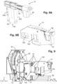
- FIG. 8A and 8B An example of a vertical alignment module 74 is illustrated in Figures 8A and 8B without and with the fixing casing.
- the module comprises a roller 90 extending in the z direction, between two parallel fixing rods 92a, 92b extending in the y axis, and fixed at their free end an arm 94 connected to an actuator 96.
- the actuator 96 makes it possible, in particular, to adjust the height of the roller 90 forming the stop surface 88 allowing the vertical alignment of the rail portion.
- the roller 90 is rotatable about an axis parallel to the z axis of the reference frame, so as to avoid any injury to the upper surface of the head of the rail portion during alignment operations.
- the vertical alignment modules 74 and lateral alignment modules 76 are complementary.
- the rail portions 84 vertically against the rollers 90, vertical alignment is ensured, and the jaws 78a, 78b, holding the rail portions 84 on either side of the longitudinal axis A, ensure their alignment with the longitudinal axis A.
- Such a system can be integrated within a welder 2 for railway rails.
- the welder 2 then comprises a system as presented on which a welding module 98 is arranged on the third chassis 62.
- the welding module 98 can preferably allow induction heating.
- this third chassis 62 is slidably mounted on the first and second chassis 14, 16 along the longitudinal axis A, and is movable by means of two actuators 64, 66 for moving the third chassis.
- through openings 100 are provided at the level of the casings 72 of the alignment modules as well as the external casing 4 of the welder 2, dimensioned to allow a vertical alignment measuring beam and a lateral alignment measuring beam to pass through them.
- These measuring beams are thus arranged opposite the sections of rail to be welded or welded. They include laser distance sensors distributed along the entire length of the beams.
- the beams are secured to the third frame 62 and extend along the longitudinal axis.
- Each of these beams is supported by the first and second frames 14, 16 by means of absorption means. deformation and vibrations.
- these deformation absorption means are rubber buffers.
- This assembly makes it possible to make these beams structurally independent of the first and second frames 14, 16 so that their positioning is not impacted by deformations of these frames 14, 16.
- step c) is followed by the control of the actuators 64, 66 for positioning the third chassis 62, so as to position the welding module vertically in the direction y of the end of the first portion of rail to be welded.
Landscapes
- Engineering & Computer Science (AREA)
- Mechanical Engineering (AREA)
- Architecture (AREA)
- Civil Engineering (AREA)
- Structural Engineering (AREA)
- Physics & Mathematics (AREA)
- Optics & Photonics (AREA)
- Machines For Laying And Maintaining Railways (AREA)
- Butt Welding And Welding Of Specific Article (AREA)
Applications Claiming Priority (2)
| Application Number | Priority Date | Filing Date | Title |
|---|---|---|---|
| FR1858343A FR3085873B1 (fr) | 2018-09-17 | 2018-09-17 | Systeme d'alignement de portions de rail pour soudeuse a induction |
| PCT/EP2019/074741 WO2020058208A1 (fr) | 2018-09-17 | 2019-09-16 | Systeme d'alignement de portions de rail pour soudeuse a induction |
Publications (3)
| Publication Number | Publication Date |
|---|---|
| EP3852968A1 EP3852968A1 (fr) | 2021-07-28 |
| EP3852968B1 true EP3852968B1 (fr) | 2025-04-09 |
| EP3852968C0 EP3852968C0 (fr) | 2025-04-09 |
Family
ID=64049417
Family Applications (1)
| Application Number | Title | Priority Date | Filing Date |
|---|---|---|---|
| EP19780159.0A Active EP3852968B1 (fr) | 2018-09-17 | 2019-09-16 | Système d'alignement de portions de rail pour soudeuse à induction |
Country Status (5)
| Country | Link |
|---|---|
| EP (1) | EP3852968B1 (pl) |
| ES (1) | ES3027933T3 (pl) |
| FR (1) | FR3085873B1 (pl) |
| PL (1) | PL3852968T3 (pl) |
| WO (1) | WO2020058208A1 (pl) |
Families Citing this family (2)
| Publication number | Priority date | Publication date | Assignee | Title |
|---|---|---|---|---|
| AT522860B1 (de) * | 2019-07-31 | 2023-05-15 | Plasser & Theurer Export Von Bahnbaumaschinen Gmbh | Schweißaggregat zum Verschweißen von Schienen eines Gleises |
| FR3118970B1 (fr) * | 2021-01-19 | 2023-01-06 | Pandrol | Ensemble pour l’alignement automatique de rails |
Family Cites Families (4)
| Publication number | Priority date | Publication date | Assignee | Title |
|---|---|---|---|---|
| DE502005003198D1 (de) * | 2005-05-18 | 2008-04-24 | Plasser Bahnbaumasch Franz | Schweissmaschine und Verfahren zum Verschweissen von Schienen eines Gleises |
| AT507243B1 (de) * | 2008-08-04 | 2010-06-15 | Plasser Bahnbaumasch Franz | Schweissaggregat zum verschweissen von schienen eines gleises |
| FR2998310B1 (fr) * | 2012-11-16 | 2015-02-06 | Anciens Etablissements Lucien Geismar Soc D | Ensemble pour un dispositif de serrage d’un tendeur de rail |
| GB2551394B (en) * | 2016-06-17 | 2020-09-09 | Mirage Ltd | Railway rail induction-welding device |
-
2018
- 2018-09-17 FR FR1858343A patent/FR3085873B1/fr active Active
-
2019
- 2019-09-16 EP EP19780159.0A patent/EP3852968B1/fr active Active
- 2019-09-16 ES ES19780159T patent/ES3027933T3/es active Active
- 2019-09-16 WO PCT/EP2019/074741 patent/WO2020058208A1/fr not_active Ceased
- 2019-09-16 PL PL19780159.0T patent/PL3852968T3/pl unknown
Also Published As
| Publication number | Publication date |
|---|---|
| FR3085873A1 (fr) | 2020-03-20 |
| EP3852968A1 (fr) | 2021-07-28 |
| WO2020058208A1 (fr) | 2020-03-26 |
| PL3852968T3 (pl) | 2025-07-21 |
| EP3852968C0 (fr) | 2025-04-09 |
| FR3085873B1 (fr) | 2021-01-15 |
| ES3027933T3 (en) | 2025-06-17 |
Similar Documents
| Publication | Publication Date | Title |
|---|---|---|
| EP2202023B1 (fr) | Outillage et procédé de positionnement bout à bout de tubes métalliques | |
| FR2677285A1 (fr) | Tete de soudage a laser. | |
| EP0622152B1 (fr) | Installation de positionnement bord à bord et de soudage au moyen d'un faisceau laser d'au moins deux flans de tÔle | |
| EP3852968B1 (fr) | Système d'alignement de portions de rail pour soudeuse à induction | |
| FR2483285A1 (fr) | Appareil pour echanger l'unite formant calibre de soudage dans un appareil de soudage automatique | |
| CA1140600A (fr) | Dispositif de reglage de deux abouts de rails a raccorder par soudure | |
| EP0501183B1 (fr) | Dispositif pour le reprofilage des rails d'une voie ferrée | |
| FR2483481A1 (fr) | Machine de construction des voies ferrees comprenant des supports pour outils de levage et de dressage | |
| EP0016664B1 (fr) | Dispositif de réglage de l'alignement et de la distance intercalaire de deux abouts de rails | |
| EP1110857B1 (fr) | Dispositif d'équilibrage d'un navire, notamment en roulis | |
| EP2934809B1 (fr) | Procédé et moule pour le soudage des extrémités de deux portions de rail | |
| FR2935715A1 (fr) | Dispositif pour la maintenance de rails | |
| FR2943266A1 (fr) | Dispositif de soudobrasage | |
| EP3480159B1 (fr) | Engin de travail en hauteur et méthode de stabilisation d'un tel engin | |
| EP0332489B1 (fr) | Dispositif de mise en place d'un véhicule ferroviaire sur un tour à reprofiler les roues | |
| FR3045425A1 (fr) | Module de poinconnage et de soudage | |
| EP0765699B1 (fr) | Châssis de redressage pour carrosserie automobile | |
| EP0977649B1 (fr) | Procede de mise en place de deux flans de tole pour etre soudes bord a bord par un faisceau a haute densite d'energie | |
| EP3802957B1 (fr) | Ensemble comprenant un rail et une presse pour le rail | |
| FR3051003A1 (fr) | Dispositif de chargement et dechargement de rails sur et a partir de wagons, et vehicule ferroviaire equipe de celui-ci | |
| FR2731239A1 (fr) | Dispositif de centrage, dispositif d'ajustement de traverse et train de pose de voie de chemin de fer | |
| FR3095557A1 (fr) | Un système de tirage des fils ou câbles d'une caténaire notamment d'une voie de chemin de fer | |
| EP3300933A1 (fr) | Vehicule fer/route pour la mise en place de catenaire | |
| EP3326885A1 (fr) | Cale pour re-enraillement de vehicule guide sur rails et procede de re-enraillement associe | |
| FR2912940A1 (fr) | Dispositif et procede d'assistance et de realisation de travaux mecaniques sur une piece montee sur un support |
Legal Events
| Date | Code | Title | Description |
|---|---|---|---|
| STAA | Information on the status of an ep patent application or granted ep patent |
Free format text: STATUS: UNKNOWN |
|
| STAA | Information on the status of an ep patent application or granted ep patent |
Free format text: STATUS: THE INTERNATIONAL PUBLICATION HAS BEEN MADE |
|
| PUAI | Public reference made under article 153(3) epc to a published international application that has entered the european phase |
Free format text: ORIGINAL CODE: 0009012 |
|
| STAA | Information on the status of an ep patent application or granted ep patent |
Free format text: STATUS: REQUEST FOR EXAMINATION WAS MADE |
|
| 17P | Request for examination filed |
Effective date: 20210416 |
|
| AK | Designated contracting states |
Kind code of ref document: A1 Designated state(s): AL AT BE BG CH CY CZ DE DK EE ES FI FR GB GR HR HU IE IS IT LI LT LU LV MC MK MT NL NO PL PT RO RS SE SI SK SM TR |
|
| DAV | Request for validation of the european patent (deleted) | ||
| DAX | Request for extension of the european patent (deleted) | ||
| STAA | Information on the status of an ep patent application or granted ep patent |
Free format text: STATUS: EXAMINATION IS IN PROGRESS |
|
| 17Q | First examination report despatched |
Effective date: 20230302 |
|
| GRAP | Despatch of communication of intention to grant a patent |
Free format text: ORIGINAL CODE: EPIDOSNIGR1 |
|
| STAA | Information on the status of an ep patent application or granted ep patent |
Free format text: STATUS: GRANT OF PATENT IS INTENDED |
|
| INTG | Intention to grant announced |
Effective date: 20240603 |
|
| GRAJ | Information related to disapproval of communication of intention to grant by the applicant or resumption of examination proceedings by the epo deleted |
Free format text: ORIGINAL CODE: EPIDOSDIGR1 |
|
| STAA | Information on the status of an ep patent application or granted ep patent |
Free format text: STATUS: EXAMINATION IS IN PROGRESS |
|
| GRAP | Despatch of communication of intention to grant a patent |
Free format text: ORIGINAL CODE: EPIDOSNIGR1 |
|
| STAA | Information on the status of an ep patent application or granted ep patent |
Free format text: STATUS: GRANT OF PATENT IS INTENDED |
|
| INTC | Intention to grant announced (deleted) | ||
| INTG | Intention to grant announced |
Effective date: 20241031 |
|
| GRAS | Grant fee paid |
Free format text: ORIGINAL CODE: EPIDOSNIGR3 |
|
| GRAA | (expected) grant |
Free format text: ORIGINAL CODE: 0009210 |
|
| STAA | Information on the status of an ep patent application or granted ep patent |
Free format text: STATUS: THE PATENT HAS BEEN GRANTED |
|
| AK | Designated contracting states |
Kind code of ref document: B1 Designated state(s): AL AT BE BG CH CY CZ DE DK EE ES FI FR GB GR HR HU IE IS IT LI LT LU LV MC MK MT NL NO PL PT RO RS SE SI SK SM TR |
|
| RAP3 | Party data changed (applicant data changed or rights of an application transferred) |
Owner name: MORNAC, JEAN-PIERRE |
|
| REG | Reference to a national code |
Ref country code: GB Ref legal event code: FG4D Free format text: NOT ENGLISH |
|
| REG | Reference to a national code |
Ref country code: CH Ref legal event code: EP |
|
| REG | Reference to a national code |
Ref country code: DE Ref legal event code: R096 Ref document number: 602019068449 Country of ref document: DE |
|
| REG | Reference to a national code |
Ref country code: IE Ref legal event code: FG4D Free format text: LANGUAGE OF EP DOCUMENT: FRENCH |
|
| U01 | Request for unitary effect filed |
Effective date: 20250507 |
|
| U07 | Unitary effect registered |
Designated state(s): AT BE BG DE DK EE FI FR IT LT LU LV MT NL PT RO SE SI Effective date: 20250513 |
|
| REG | Reference to a national code |
Ref country code: ES Ref legal event code: FG2A Ref document number: 3027933 Country of ref document: ES Kind code of ref document: T3 Effective date: 20250617 |
|
| U20 | Renewal fee for the european patent with unitary effect paid |
Year of fee payment: 7 Effective date: 20250814 |
|
| REG | Reference to a national code |
Ref country code: CH Ref legal event code: U11 Free format text: ST27 STATUS EVENT CODE: U-0-0-U10-U11 (AS PROVIDED BY THE NATIONAL OFFICE) Effective date: 20251001 |
|
| PG25 | Lapsed in a contracting state [announced via postgrant information from national office to epo] |
Ref country code: NO Free format text: LAPSE BECAUSE OF FAILURE TO SUBMIT A TRANSLATION OF THE DESCRIPTION OR TO PAY THE FEE WITHIN THE PRESCRIBED TIME-LIMIT Effective date: 20250709 Ref country code: GR Free format text: LAPSE BECAUSE OF FAILURE TO SUBMIT A TRANSLATION OF THE DESCRIPTION OR TO PAY THE FEE WITHIN THE PRESCRIBED TIME-LIMIT Effective date: 20250710 |
|
| PGFP | Annual fee paid to national office [announced via postgrant information from national office to epo] |
Ref country code: PL Payment date: 20250825 Year of fee payment: 7 |
|
| PGFP | Annual fee paid to national office [announced via postgrant information from national office to epo] |
Ref country code: GB Payment date: 20250919 Year of fee payment: 7 |
|
| PG25 | Lapsed in a contracting state [announced via postgrant information from national office to epo] |
Ref country code: HR Free format text: LAPSE BECAUSE OF FAILURE TO SUBMIT A TRANSLATION OF THE DESCRIPTION OR TO PAY THE FEE WITHIN THE PRESCRIBED TIME-LIMIT Effective date: 20250409 |
|
| PG25 | Lapsed in a contracting state [announced via postgrant information from national office to epo] |
Ref country code: RS Free format text: LAPSE BECAUSE OF FAILURE TO SUBMIT A TRANSLATION OF THE DESCRIPTION OR TO PAY THE FEE WITHIN THE PRESCRIBED TIME-LIMIT Effective date: 20250709 |
|
| PG25 | Lapsed in a contracting state [announced via postgrant information from national office to epo] |
Ref country code: IS Free format text: LAPSE BECAUSE OF FAILURE TO SUBMIT A TRANSLATION OF THE DESCRIPTION OR TO PAY THE FEE WITHIN THE PRESCRIBED TIME-LIMIT Effective date: 20250809 |
|
| PG25 | Lapsed in a contracting state [announced via postgrant information from national office to epo] |
Ref country code: SM Free format text: LAPSE BECAUSE OF FAILURE TO SUBMIT A TRANSLATION OF THE DESCRIPTION OR TO PAY THE FEE WITHIN THE PRESCRIBED TIME-LIMIT Effective date: 20250409 |
|
| PGFP | Annual fee paid to national office [announced via postgrant information from national office to epo] |
Ref country code: CH Payment date: 20251001 Year of fee payment: 7 |
|
| PG25 | Lapsed in a contracting state [announced via postgrant information from national office to epo] |
Ref country code: CZ Free format text: LAPSE BECAUSE OF FAILURE TO SUBMIT A TRANSLATION OF THE DESCRIPTION OR TO PAY THE FEE WITHIN THE PRESCRIBED TIME-LIMIT Effective date: 20250409 |
|
| PG25 | Lapsed in a contracting state [announced via postgrant information from national office to epo] |
Ref country code: SK Free format text: LAPSE BECAUSE OF FAILURE TO SUBMIT A TRANSLATION OF THE DESCRIPTION OR TO PAY THE FEE WITHIN THE PRESCRIBED TIME-LIMIT Effective date: 20250409 |
|
| PGFP | Annual fee paid to national office [announced via postgrant information from national office to epo] |
Ref country code: ES Payment date: 20251015 Year of fee payment: 7 |
|
| PLBE | No opposition filed within time limit |
Free format text: ORIGINAL CODE: 0009261 |
|
| STAA | Information on the status of an ep patent application or granted ep patent |
Free format text: STATUS: NO OPPOSITION FILED WITHIN TIME LIMIT |
|
| REG | Reference to a national code |
Ref country code: CH Ref legal event code: L10 Free format text: ST27 STATUS EVENT CODE: U-0-0-L10-L00 (AS PROVIDED BY THE NATIONAL OFFICE) Effective date: 20260218 |
|
| 26N | No opposition filed |
Effective date: 20260112 |