EP3853089B1 - Redondance de freinage dans un groupe de traction - Google Patents
Redondance de freinage dans un groupe de traction Download PDFInfo
- Publication number
- EP3853089B1 EP3853089B1 EP18783277.9A EP18783277A EP3853089B1 EP 3853089 B1 EP3853089 B1 EP 3853089B1 EP 18783277 A EP18783277 A EP 18783277A EP 3853089 B1 EP3853089 B1 EP 3853089B1
- Authority
- EP
- European Patent Office
- Prior art keywords
- control unit
- locomotive
- relay
- air brake
- brake control
- Prior art date
- Legal status (The legal status is an assumption and is not a legal conclusion. Google has not performed a legal analysis and makes no representation as to the accuracy of the status listed.)
- Active
Links
Images


Classifications
-
- B—PERFORMING OPERATIONS; TRANSPORTING
- B60—VEHICLES IN GENERAL
- B60T—VEHICLE BRAKE CONTROL SYSTEMS OR PARTS THEREOF; BRAKE CONTROL SYSTEMS OR PARTS THEREOF, IN GENERAL; ARRANGEMENT OF BRAKING ELEMENTS ON VEHICLES IN GENERAL; PORTABLE DEVICES FOR PREVENTING UNWANTED MOVEMENT OF VEHICLES; VEHICLE MODIFICATIONS TO FACILITATE COOLING OF BRAKES
- B60T17/00—Component parts, details, or accessories of power brake systems not covered by groups B60T8/00, B60T13/00 or B60T15/00, or presenting other characteristic features
- B60T17/18—Safety devices; Monitoring
- B60T17/22—Devices for monitoring or checking brake systems; Signal devices
- B60T17/228—Devices for monitoring or checking brake systems; Signal devices for railway vehicles
-
- B—PERFORMING OPERATIONS; TRANSPORTING
- B60—VEHICLES IN GENERAL
- B60T—VEHICLE BRAKE CONTROL SYSTEMS OR PARTS THEREOF; BRAKE CONTROL SYSTEMS OR PARTS THEREOF, IN GENERAL; ARRANGEMENT OF BRAKING ELEMENTS ON VEHICLES IN GENERAL; PORTABLE DEVICES FOR PREVENTING UNWANTED MOVEMENT OF VEHICLES; VEHICLE MODIFICATIONS TO FACILITATE COOLING OF BRAKES
- B60T13/00—Transmitting braking action from initiating means to ultimate brake actuator with power assistance or drive; Brake systems incorporating such transmitting means, e.g. air-pressure brake systems
- B60T13/10—Transmitting braking action from initiating means to ultimate brake actuator with power assistance or drive; Brake systems incorporating such transmitting means, e.g. air-pressure brake systems with fluid assistance, drive, or release
- B60T13/24—Transmitting braking action from initiating means to ultimate brake actuator with power assistance or drive; Brake systems incorporating such transmitting means, e.g. air-pressure brake systems with fluid assistance, drive, or release the fluid being gaseous
-
- B—PERFORMING OPERATIONS; TRANSPORTING
- B60—VEHICLES IN GENERAL
- B60T—VEHICLE BRAKE CONTROL SYSTEMS OR PARTS THEREOF; BRAKE CONTROL SYSTEMS OR PARTS THEREOF, IN GENERAL; ARRANGEMENT OF BRAKING ELEMENTS ON VEHICLES IN GENERAL; PORTABLE DEVICES FOR PREVENTING UNWANTED MOVEMENT OF VEHICLES; VEHICLE MODIFICATIONS TO FACILITATE COOLING OF BRAKES
- B60T13/00—Transmitting braking action from initiating means to ultimate brake actuator with power assistance or drive; Brake systems incorporating such transmitting means, e.g. air-pressure brake systems
- B60T13/10—Transmitting braking action from initiating means to ultimate brake actuator with power assistance or drive; Brake systems incorporating such transmitting means, e.g. air-pressure brake systems with fluid assistance, drive, or release
- B60T13/66—Electrical control in fluid-pressure brake systems
- B60T13/662—Electrical control in fluid-pressure brake systems characterised by specified functions of the control system components
-
- B—PERFORMING OPERATIONS; TRANSPORTING
- B60—VEHICLES IN GENERAL
- B60T—VEHICLE BRAKE CONTROL SYSTEMS OR PARTS THEREOF; BRAKE CONTROL SYSTEMS OR PARTS THEREOF, IN GENERAL; ARRANGEMENT OF BRAKING ELEMENTS ON VEHICLES IN GENERAL; PORTABLE DEVICES FOR PREVENTING UNWANTED MOVEMENT OF VEHICLES; VEHICLE MODIFICATIONS TO FACILITATE COOLING OF BRAKES
- B60T13/00—Transmitting braking action from initiating means to ultimate brake actuator with power assistance or drive; Brake systems incorporating such transmitting means, e.g. air-pressure brake systems
- B60T13/10—Transmitting braking action from initiating means to ultimate brake actuator with power assistance or drive; Brake systems incorporating such transmitting means, e.g. air-pressure brake systems with fluid assistance, drive, or release
- B60T13/66—Electrical control in fluid-pressure brake systems
- B60T13/68—Electrical control in fluid-pressure brake systems by electrically-controlled valves
- B60T13/683—Electrical control in fluid-pressure brake systems by electrically-controlled valves in pneumatic systems or parts thereof
-
- B—PERFORMING OPERATIONS; TRANSPORTING
- B60—VEHICLES IN GENERAL
- B60T—VEHICLE BRAKE CONTROL SYSTEMS OR PARTS THEREOF; BRAKE CONTROL SYSTEMS OR PARTS THEREOF, IN GENERAL; ARRANGEMENT OF BRAKING ELEMENTS ON VEHICLES IN GENERAL; PORTABLE DEVICES FOR PREVENTING UNWANTED MOVEMENT OF VEHICLES; VEHICLE MODIFICATIONS TO FACILITATE COOLING OF BRAKES
- B60T8/00—Arrangements for adjusting wheel-braking force to meet varying vehicular or ground-surface conditions, e.g. limiting or varying distribution of braking force
- B60T8/17—Using electrical or electronic regulation means to control braking
- B60T8/1701—Braking or traction control means specially adapted for particular types of vehicles
- B60T8/1705—Braking or traction control means specially adapted for particular types of vehicles for rail vehicles
-
- B—PERFORMING OPERATIONS; TRANSPORTING
- B61—RAILWAYS
- B61H—BRAKES OR OTHER RETARDING DEVICES SPECIALLY ADAPTED FOR RAIL VEHICLES; ARRANGEMENT OR DISPOSITION THEREOF IN RAIL VEHICLES
- B61H13/00—Actuating rail-vehicle brakes
- B61H13/34—Details
-
- B—PERFORMING OPERATIONS; TRANSPORTING
- B60—VEHICLES IN GENERAL
- B60T—VEHICLE BRAKE CONTROL SYSTEMS OR PARTS THEREOF; BRAKE CONTROL SYSTEMS OR PARTS THEREOF, IN GENERAL; ARRANGEMENT OF BRAKING ELEMENTS ON VEHICLES IN GENERAL; PORTABLE DEVICES FOR PREVENTING UNWANTED MOVEMENT OF VEHICLES; VEHICLE MODIFICATIONS TO FACILITATE COOLING OF BRAKES
- B60T2270/00—Further aspects of brake control systems not otherwise provided for
- B60T2270/40—Failsafe aspects of brake control systems
- B60T2270/402—Back-up
Definitions
- the present invention to train braking systems and, more specifically, to a system and method for providing redundancy of braking system control in the locomotive consist of a train.
- Most trains are powered by multiple locomotives that combine to provide the tractive force needed to move the rail cars.
- one locomotive is designated as the lead locomotive and is also tasked with the responsible of managing all of the braking efforts of the train. More specifically, the driver of the train uses the handles of the electronic brake valve (EBV) of the lead locomotive to operate the air brake control unit of the lead locomotive, which is in control all of the locomotive brake and the rail car brakes of the train.
- EBV electronic brake valve
- US 2015/083529 A1 discloses a pneumatic brake system allowing brake redundancy by communicating brake commands through locomotive brake interfaces of different locomotives and a locomotive interconnection cable between them.
- the present invention can easily address a failure of an air brake control unit by providing redundant control via a second air brake control unit.
- the air brake control unit of the present invention is defined in independent claim 1.
- the first electro-pneumatic control unit is configured to respond to a second braking command signal received from the second air brake control unit via the inter-unit connector if the relay has connected power to the electro-pneumatic control unit.
- the first electronic brake valve connector is also configured to send the braking command signal to the second air brake control unit if the relay has disconnected power from the electro-pneumatic control unit.
- the relay is controlled externally, such as by a locomotive control system positioned in a cab of the locomotive.
- the present invention also includes a system for providing brake redundancy across a locomotive consist.
- This system is defined in the independent system claim.
- the first air brake control unit is configured to respond to the second braking command signal if the second relay has disconnected power from the second air brake control unit and the first relay has connected power the first air brake unit.
- the second air brake control unit is configured to respond to the first braking command signal if the first rely has disconnected power from the first air brake control unit and the second relay has connected power to the second air brake control unit.
- the first relay and the second relay are controlled externally, such as by a locomotive control system positioned in a cab of the locomotive, so that the operator can operate the brakes of the train from either of the locomotives using either of the air brake control units as desired.
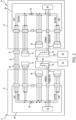
- System 10 comprises an air brake control unit 14 in lead locomotive A that has connectors for coupling to system power 16 and to an electronic brake valve 18 commonly used by the driver in the cab of locomotive A.
- electronic brake valve 18 will send control commands based on the movement of user handles to an air brake control unit 14 to control the operation of the locomotive brakes on all locomotives in the consist and the rail car brakes of the train.
- Brake redundancy system 10 provides for redundancy by controlling the delivery of power to the various components of the locomotive and train braking system. Control over the interconnection to system power 16 is accomplished via a relay 20, such as a relay coil, that can selectively connect and disconnect air brake control unit 14 of one of lead locomotive A and trail locomotive B from system power 16. As explained below, portions of air brake control unit 14 to which power has been disconnected may then be provided with power from the other of lead locomotive A and trail locomotive B so that electronic brake valve 18 of either of lead locomotive A and trail locomotive B can control the air brake control unit 14 that is still receiving power. As a result, either locomotive may have its air brake control unit 14 removed from service, and the train braking system can be controlled using the other air brake control unit 14 from the electronic brake valve 18 of either locomotive.
- a relay 20 such as a relay coil
- Relay 20 may be placed under the control of the locomotive control system 22 of its corresponding locomotive.
- Locomotive control system 22 may be a conventional train control and energy management system, such as the LEADER ® system available from New York Air Brake of Watertown, New York, that contains data on the train's length and weight, car types, power distribution along with a detailed track profile for predicting train performance and optimizing train handling and fuel economy. It should be recognized that relay 20 can thus be activated by locomotive control system 22 to connect or disconnect system power 16 from air brake control unit 14.
- system power 16 includes first and second inputs (A and B) to air brake control unit 14.
- First input A (such as the return power line) and second input B (such as the positive power line) are fed to a power converter 34 that conditions the incoming power and couples conditioned power to the components of air brake control unit 14.
- system power 26 typically involves 24 volt service provided via a powered line and a power return line. It should be recognized that the present invention may be used with any conventional power service arrangements and, for simplicity, only the power couplings to the various components have been illustrated.
- Air brake control unit 14 further comprises an inter-unit connector 24 interconnected to system power 16 and to electronic brake valve 18.
- Inter-unit connector 24 is configured for electronic interconnection to a corresponding inter-unit connector 24 of corresponding air brake control unit 14 in trail locomotive B.
- inter-unit connector 24 may include a receptacle for coupling to an inter-unit cable 30 that extends from lead locomotive A to trail locomotive B.
- Inter-unit cable 30 is similarly coupled to a corresponding inter-unit connector 24 of trail locomotive B.
- a power blocking diode 26 is connected between system power 16 and an inter-unit connector 24 on the positive power line to prevent any back feed to an unpowered air brake control unit 14 from a powered corresponding air brake control unit 14 through inter-unit cable 20. Power blocking diode 26 may thus comprise other conventional electronic devices or circuits for preventing unwanted power backflow.
- Air brake control unit 14 additionally comprises an electro-pneumatic control unit 32 that manages the pneumatic interfaces between the locomotive brake system and the locomotive consist.
- electro-pneumatic control unit 32 controls the locomotive brake cylinders, the train brake pipe, the independent application and release pipe, and the actuating pipe.
- electro-pneumatic control unit 32 is responsible for implementing the braking commands received from electronic brake valve 18 in response to movement of the brake handles by an operator. Disconnection of system power 16 by operation of relay 20 prevents electro-pneumatic control unit 32 from responding to brake commands received from electronic brake valve 18.
- Air brake control unit 14 further includes a relay control portion 36.
- Relay control portion 36 contains application specific settings for the brake system and configures and monitors the other nodes within the system.
- Relay control portion 36 also contains relays and drivers to interface to electrical inputs and outputs to the vehicle systems.
- the various power couplings may be arranged is a power supply junction box 38 incorporated into air brake control unit 14 to couple to power the various brake control components.
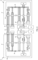
- Locomotive control system 22 may thus control whether air brake control unit 14 on lead locomotive A or corresponding air brake control unit 14 on trail locomotive B is powered for the purposes of controlling the braking systems of the train. As electronic brake valve 18 of lead locomotive A and corresponding electronic brake valve 18 of trail locomotive B remains powered, either may be used to send brake commands. As a result, an operator may select and use either air electronic brake valve 18 of lead locomotive A or corresponding electronic brake valve 18 trail locomotive B to operate whichever of air brake control unit 14 of lead locomotive A or corresponding air brake control unit 14 of trail locomotive B has been powered by locomotive control system 22.
- the present invention thus allows for both electronic brake valves 18 of locomotive A and locomotive B to be powered, but only one of power supply junction box 38, electro-pneumatic control unit 32 and relay control portion 36 at a time.
- Locomotive control system 22 of locomotive A and locomotive control system 22 of locomotive B coordinate which air brake control unit 14 is to be fully powered.
- locomotive control system 22 of locomotive A when air brake control unit 14 of locomotive A is to be powered, locomotive control system 22 of locomotive A will energize relay 20 of locomotive A, to provide system power to power supply converter 24 and power supply junction box 38 of locomotive A. This, in turn, provides 24 volt power to electro-pneumatic control unit 32 of locomotive A, relay control portion 36 of locomotive A, air brake control unit 14 of locomotive A.
- Inter-unit cable 30 allows power from locomotive A to power the relevant portions of air brake control unit 14 of locomotive B.
- Power blocking diode 26 of locomotive B prevents power provided by locomotive A from reaching the portion of air brake control unit 14 of locomotive B that are to remain unpowered.
- electronic brake valve 18 of either locomotive A or locomotive B is powered and thus can provide brake commands to electro-pneumatic control unit 32 of locomotive A without any command being acted upon by electro-pneumatic control unit 32 of locomotive B because the present invention has prevented electro-pneumatic control unit 32 of locomotive B from receiving power.
- locomotive control system 22 of locomotive B will energize relay 20 of locomotive B to provide system power to power supply converter 24 of locomotive B and power supply junction box 38 of locomotive B. This, in turn, provides 24 volt power to electro-pneumatic control unit 32 of locomotive B, relay control portion 36 of locomotive B, and air brake control unit 14 of locomotive B.
- Inter-unit cable 30 allows power from locomotive B to power the relevant portions of air brake control unit 14 of locomotive A.
- Power blocking diode 26 of locomotive A prevents power provided by locomotive B from reaching the portion of air brake control unit 14 of locomotive A that are to remain unpowered.
- electronic brake valve 18 of either locomotive A or locomotive B is powered and thus can provide brake commands to electro-pneumatic control unit 32 of locomotive B without any command being acted upon by electro-pneumatic control unit 32 of locomotive A because the present invention has prevented electro-pneumatic control unit 32 of locomotive A from receiving power.
- the present invention may be a system, a method, and/or a computer program associated therewith and is described herein with reference to flowcharts and block diagrams of methods and systems.
- the flowchart and block diagrams illustrate the architecture, functionality, and operation of possible implementations of systems, methods, and computer programs of the present invention. It should be understood that each block of the flowcharts and block diagrams can be implemented by computer readable program instructions in software, firmware, or dedicated analog or digital circuits. These computer readable program instructions may be implemented on the processor of a general purpose computer, a special purpose computer, or other programmable data processing apparatus to produce a machine that implements a part or all of any of the blocks in the flowcharts and block diagrams.
- Each block in the flowchart or block diagrams may represent a module, segment, or portion of instructions, which comprises one or more executable instructions for implementing the specified logical functions. It should also be noted that each block of the block diagrams and flowchart illustrations, or combinations of blocks in the block diagrams and flowcharts, can be implemented by special purpose hardware-based systems that perform the specified functions or acts or carry out combinations of special purpose hardware and computer instructions.
Landscapes
- Engineering & Computer Science (AREA)
- Mechanical Engineering (AREA)
- Transportation (AREA)
- Braking Systems And Boosters (AREA)
Claims (12)
- Unité (14) de commande de frein pneumatique, comprenant :un connecteur de premier robinet de frein électronique pour recevoir un premier signal de commande de freinage depuis un premier robinet de frein électronique (18) d'une première locomotive (A) ;une première unité (32) de commande électropneumatique pour opérer un système de freinage d'un train en réponse au premier signal de commande de freinage reçu depuis le premier robinet de frein électronique ;un relais (20) pour sélectivement connecter et déconnecter une source (16) d'énergie de la première locomotive à l'unité de commande de frein pneumatique ; etun premier connecteur inter-unités (24) interconnecté à la source d'énergie et au premier robinet de frein électronique et configuré pour établir une connexion d'alimentation d'énergie entre le premier robinet de frein électronique et une deuxième unité de commande de frein pneumatique d'une deuxième locomotive (B) ainsi qu'entre un deuxième robinet de frein électronique de la deuxième locomotive et l'unité de commande de frein pneumatique.
- Unité (14) de commande de frein pneumatique selon la revendication 1, dans laquelle la première unité (32) de commande électropneumatique est configurée pour répondre à un deuxième signal de commande de freinage reçu depuis la deuxième unité de commande de frein pneumatique par l'intermédiaire du premier connecteur inter-unités (24) si le relais (20) a connecté l'énergie à la première unité de commande électropneumatique.
- Unité (14) de commande de frein pneumatique selon la revendication 2, dans laquelle le connecteur de premier robinet de frein électronique est configuré pour envoyer le premier signal de commande de freinage à la deuxième unité de commande électropneumatique de la deuxième unité de commande de frein pneumatique si le relais (20) a déconnecté l'énergie de la première unité (32) de commande électropneumatique.
- Unité (14) de commande de frein pneumatique selon la revendication 3, dans laquelle le relais (20) est configuré pour être commandé de façon externe par un système (22) de commande de locomotive positionné dans une cabine de la première locomotive (A).
- Unité (14) de commande de frein pneumatique selon la revendication 3, comprenant en outre une partie (36) de commande de relais pour commander le relais, la partie de commande de relais incluant des paramètres à application spécifique pour un système (10) de redondance de frein d'un groupe de traction (12) incluant les première et deuxième locomotives (A, B).
- Unité de commande de frein pneumatique selon la revendication 5, dans laquelle le connecteur de robinet de frein électronique, l'unité (32) de commande électropneumatique, et le relais (20) sont agencés dans un boîtier (38) de jonction d'alimentation électrique.
- Système (10) pour fournir une redondance de frein dans un groupe de traction (12), comprenant :une première unité (14) de commande de frein pneumatique ayant un connecteur de premier robinet de frein électronique pour recevoir un premier signal de commande de freinage depuis un premier robinet de frein électronique (18) d'une première locomotive (A), une première unité (32) de commande électropneumatique pour opérer le système de freinage d'un train en réponse au premier signal de commande de freinage reçu depuis le premier robinet de frein électronique, un premier relais (20) pour sélectivement connecter et déconnecter une première source (26) d'énergie de la première locomotive à la première unité de commande de frein pneumatique, et un premier connecteur inter-unités (24) interconnecté à la première source d'énergie et au premier robinet de frein électronique ;une deuxième unité (14) de commande de frein pneumatique ayant un connecteur de deuxième robinet de frein électronique pour recevoir un deuxième signal de commande de freinage depuis un deuxième robinet de frein électronique (18) d'une deuxième locomotive (B), une deuxième unité (32) de commande électropneumatique pour opérer le système de freinage du train en réponse au deuxième signal de commande de freinage reçu depuis le deuxième robinet de frein électronique, un deuxième relais (20) pour sélectivement connecter et déconnecter une deuxième source (26) d'énergie de la deuxième locomotive (B) à la deuxième unité de commande de frein pneumatique, et un deuxième connecteur inter-unités (24) interconnecté à la deuxième source d'énergie et au deuxième robinet de frein électronique ; etun câble (30) inter-unités connectant le premier connecteur inter-unités au deuxième connecteur inter-unités et permettant à l'énergie provenant d'une des première et deuxième locomotives d'alimenter la première ou la deuxième unité de commande de frein pneumatique respective de l'autre des première et deuxième locomotives.
- Système selon la revendication 7, dans lequel la première unité (14) de commande de frein pneumatique est configurée pour répondre au deuxième signal de commande de freinage si le deuxième relais (20) a déconnecté l'énergie de la deuxième unité (14) de commande de frein pneumatique et le premier relais (20) a connecté l'énergie à la première unité de commande de frein pneumatique.
- Système selon la revendication 8, dans lequel la deuxième unité (14) de commande de frein pneumatique est configurée pour répondre au premier signal de commande de freinage si le premier relais (20) a déconnecté l'énergie de la première unité (14) de commande de frein pneumatique et le deuxième relais (20) a connecté l'énergie à la deuxième unité de commande de frein pneumatique.
- Système selon la revendication 9, dans lequel le premier relais (20) et le deuxième relais (20) sont commandés de façon externe par un système (22) de commande de locomotive positionné dans une cabine de la première ou de la deuxième locomotive (A, B).
- Système selon la revendication 9, comprenant en outre une des première et deuxième parties (36) de commande de relais pour commander les premier et deuxième relais respectifs, les parties de commande de relais incluant des paramètres à application spécifique pour un système (10) de redondance de frein d'un groupe de traction (12) incluant les première et deuxième locomotives (A, B).
- Système selon la revendication 11, dans lequel les premier et deuxième connecteurs de robinet de frein électroniques, les première et deuxième unités (32) de commande électropneumatique, et les premier et deuxième relais (20) sont agencés dans des premier et deuxième boîtiers (38) respectifs de jonction d'alimentation électrique.
Applications Claiming Priority (2)
| Application Number | Priority Date | Filing Date | Title |
|---|---|---|---|
| PCT/US2018/051856 WO2020060552A1 (fr) | 2018-09-20 | 2018-09-20 | Redondance de freinage dans un groupe de traction |
| US16/136,342 US11052893B2 (en) | 2018-09-20 | 2018-09-20 | Brake redundancy in a locomotive consist |
Publications (2)
| Publication Number | Publication Date |
|---|---|
| EP3853089A1 EP3853089A1 (fr) | 2021-07-28 |
| EP3853089B1 true EP3853089B1 (fr) | 2023-05-10 |
Family
ID=63794708
Family Applications (1)
| Application Number | Title | Priority Date | Filing Date |
|---|---|---|---|
| EP18783277.9A Active EP3853089B1 (fr) | 2018-09-20 | 2018-09-20 | Redondance de freinage dans un groupe de traction |
Country Status (3)
| Country | Link |
|---|---|
| US (1) | US11052893B2 (fr) |
| EP (1) | EP3853089B1 (fr) |
| WO (1) | WO2020060552A1 (fr) |
Families Citing this family (4)
| Publication number | Priority date | Publication date | Assignee | Title |
|---|---|---|---|---|
| DE102019133011A1 (de) * | 2019-12-04 | 2021-06-10 | Zf Cv Systems Global Gmbh | Monostabil und fehlertolerant ausgelegte Feststellbremsventilanordnung |
| MX2023014972A (es) * | 2021-07-01 | 2024-02-08 | New York Air Brake Llc | Modalidad de intercambio consistente con mitigacion de rodadura. |
| US20240416888A1 (en) * | 2021-10-29 | 2024-12-19 | Faiveley Transport Rail Technologies India Private Limited | Electric bake control system |
| CN114162103B (zh) * | 2021-12-30 | 2022-12-16 | 国能铁路装备有限责任公司 | 电制动控制系统及铁路车辆 |
Family Cites Families (10)
| Publication number | Priority date | Publication date | Assignee | Title |
|---|---|---|---|---|
| US4582280A (en) * | 1983-09-14 | 1986-04-15 | Harris Corporation | Railroad communication system |
| US5718487A (en) * | 1996-01-23 | 1998-02-17 | Westinghouse Air Brake Company | Brake control system for doubled ended locomotive |
| US6401015B1 (en) * | 1997-10-14 | 2002-06-04 | Scot Stewart | Distributed power and electronic air brake control system for a train and associated methods |
| US7841672B2 (en) * | 2005-09-16 | 2010-11-30 | New York Air Brake Corporation | Electronic brake controller with selectable display |
| US8346414B2 (en) * | 2009-03-16 | 2013-01-01 | Ztr Control Systems | System and method for determining whether a locomotive in a consist is in leading mode or trailing mode |
| US8682513B2 (en) * | 2011-04-14 | 2014-03-25 | General Electric Company | Communication management system and method for a rail vehicle |
| WO2013010162A2 (fr) * | 2011-07-14 | 2013-01-17 | General Electric Company | Procédé et système pour commande de véhicule ferroviaire |
| US8924117B2 (en) * | 2012-05-04 | 2014-12-30 | Wabtec Holding Corp. | Brake monitoring system for an air brake arrangement |
| US9868454B2 (en) * | 2013-09-26 | 2018-01-16 | FAIVELEY TRANSPORT ITALIA S. p. A. | Pneumatic brake system redundancy in locomotive consists |
| US9321468B2 (en) * | 2014-05-04 | 2016-04-26 | New York Air Brake Llc | Configurable locomotive brake controller |
-
2018
- 2018-09-20 EP EP18783277.9A patent/EP3853089B1/fr active Active
- 2018-09-20 WO PCT/US2018/051856 patent/WO2020060552A1/fr not_active Ceased
- 2018-09-20 US US16/136,342 patent/US11052893B2/en active Active
Also Published As
| Publication number | Publication date |
|---|---|
| US20200094804A1 (en) | 2020-03-26 |
| WO2020060552A1 (fr) | 2020-03-26 |
| EP3853089A1 (fr) | 2021-07-28 |
| US11052893B2 (en) | 2021-07-06 |
Similar Documents
| Publication | Publication Date | Title |
|---|---|---|
| EP3853089B1 (fr) | Redondance de freinage dans un groupe de traction | |
| US7004550B2 (en) | Integrated train electrical and pneumatic brakes | |
| US11180128B2 (en) | System and method for controlling centralized brake of vehicles, a motor train set brake control system | |
| CN101511656B (zh) | 有线分布式电源的接口系统 | |
| AU737236B2 (en) | Locomotive brake control unit with dynamic brake interlock | |
| JP2641095B2 (ja) | 車両の付随車用圧力媒体制動装置 | |
| CA2508406C (fr) | Systeme d'interface entre des systemes de freinage pneumatique et des systemes de freinage electro-pneumatique | |
| US8082086B2 (en) | Trailer vehicle brake-control module | |
| EP3049304B1 (fr) | Redondance d'un système de frein pneumatique dans des groupes de locomotives | |
| WO2004054839A9 (fr) | Systeme d'interface entre des systemes de freinage pneumatique et des systemes de freinage electro-pneumatique | |
| EP1053148B1 (fr) | Freins electropneumatiques integres pour trains | |
| US10144403B2 (en) | Electronic configurable equalizing reservoir backup system | |
| US20250131828A1 (en) | System for monitoring the integrity of a convoy of vehicles and corresponding procedure | |
| Deb et al. | LOCOMOTIVE RAIL POWER DISTRIBUTION SYSTEM (A REVIEW) |
Legal Events
| Date | Code | Title | Description |
|---|---|---|---|
| STAA | Information on the status of an ep patent application or granted ep patent |
Free format text: STATUS: UNKNOWN |
|
| STAA | Information on the status of an ep patent application or granted ep patent |
Free format text: STATUS: THE INTERNATIONAL PUBLICATION HAS BEEN MADE |
|
| PUAI | Public reference made under article 153(3) epc to a published international application that has entered the european phase |
Free format text: ORIGINAL CODE: 0009012 |
|
| STAA | Information on the status of an ep patent application or granted ep patent |
Free format text: STATUS: REQUEST FOR EXAMINATION WAS MADE |
|
| 17P | Request for examination filed |
Effective date: 20210225 |
|
| AK | Designated contracting states |
Kind code of ref document: A1 Designated state(s): AL AT BE BG CH CY CZ DE DK EE ES FI FR GB GR HR HU IE IS IT LI LT LU LV MC MK MT NL NO PL PT RO RS SE SI SK SM TR |
|
| DAV | Request for validation of the european patent (deleted) | ||
| DAX | Request for extension of the european patent (deleted) | ||
| GRAP | Despatch of communication of intention to grant a patent |
Free format text: ORIGINAL CODE: EPIDOSNIGR1 |
|
| STAA | Information on the status of an ep patent application or granted ep patent |
Free format text: STATUS: GRANT OF PATENT IS INTENDED |
|
| INTG | Intention to grant announced |
Effective date: 20221114 |
|
| GRAS | Grant fee paid |
Free format text: ORIGINAL CODE: EPIDOSNIGR3 |
|
| GRAA | (expected) grant |
Free format text: ORIGINAL CODE: 0009210 |
|
| STAA | Information on the status of an ep patent application or granted ep patent |
Free format text: STATUS: THE PATENT HAS BEEN GRANTED |
|
| AK | Designated contracting states |
Kind code of ref document: B1 Designated state(s): AL AT BE BG CH CY CZ DE DK EE ES FI FR GB GR HR HU IE IS IT LI LT LU LV MC MK MT NL NO PL PT RO RS SE SI SK SM TR |
|
| REG | Reference to a national code |
Ref country code: GB Ref legal event code: FG4D |
|
| REG | Reference to a national code |
Ref country code: AT Ref legal event code: REF Ref document number: 1566412 Country of ref document: AT Kind code of ref document: T Effective date: 20230515 Ref country code: CH Ref legal event code: EP |
|
| REG | Reference to a national code |
Ref country code: DE Ref legal event code: R096 Ref document number: 602018049680 Country of ref document: DE |
|
| REG | Reference to a national code |
Ref country code: IE Ref legal event code: FG4D |
|
| REG | Reference to a national code |
Ref country code: LT Ref legal event code: MG9D |
|
| REG | Reference to a national code |
Ref country code: NL Ref legal event code: MP Effective date: 20230510 |
|
| REG | Reference to a national code |
Ref country code: AT Ref legal event code: MK05 Ref document number: 1566412 Country of ref document: AT Kind code of ref document: T Effective date: 20230510 |
|
| PG25 | Lapsed in a contracting state [announced via postgrant information from national office to epo] |
Ref country code: SE Free format text: LAPSE BECAUSE OF FAILURE TO SUBMIT A TRANSLATION OF THE DESCRIPTION OR TO PAY THE FEE WITHIN THE PRESCRIBED TIME-LIMIT Effective date: 20230510 Ref country code: PT Free format text: LAPSE BECAUSE OF FAILURE TO SUBMIT A TRANSLATION OF THE DESCRIPTION OR TO PAY THE FEE WITHIN THE PRESCRIBED TIME-LIMIT Effective date: 20230911 Ref country code: NO Free format text: LAPSE BECAUSE OF FAILURE TO SUBMIT A TRANSLATION OF THE DESCRIPTION OR TO PAY THE FEE WITHIN THE PRESCRIBED TIME-LIMIT Effective date: 20230810 Ref country code: NL Free format text: LAPSE BECAUSE OF FAILURE TO SUBMIT A TRANSLATION OF THE DESCRIPTION OR TO PAY THE FEE WITHIN THE PRESCRIBED TIME-LIMIT Effective date: 20230510 Ref country code: ES Free format text: LAPSE BECAUSE OF FAILURE TO SUBMIT A TRANSLATION OF THE DESCRIPTION OR TO PAY THE FEE WITHIN THE PRESCRIBED TIME-LIMIT Effective date: 20230510 Ref country code: AT Free format text: LAPSE BECAUSE OF FAILURE TO SUBMIT A TRANSLATION OF THE DESCRIPTION OR TO PAY THE FEE WITHIN THE PRESCRIBED TIME-LIMIT Effective date: 20230510 |
|
| PG25 | Lapsed in a contracting state [announced via postgrant information from national office to epo] |
Ref country code: RS Free format text: LAPSE BECAUSE OF FAILURE TO SUBMIT A TRANSLATION OF THE DESCRIPTION OR TO PAY THE FEE WITHIN THE PRESCRIBED TIME-LIMIT Effective date: 20230510 Ref country code: PL Free format text: LAPSE BECAUSE OF FAILURE TO SUBMIT A TRANSLATION OF THE DESCRIPTION OR TO PAY THE FEE WITHIN THE PRESCRIBED TIME-LIMIT Effective date: 20230510 Ref country code: LV Free format text: LAPSE BECAUSE OF FAILURE TO SUBMIT A TRANSLATION OF THE DESCRIPTION OR TO PAY THE FEE WITHIN THE PRESCRIBED TIME-LIMIT Effective date: 20230510 Ref country code: LT Free format text: LAPSE BECAUSE OF FAILURE TO SUBMIT A TRANSLATION OF THE DESCRIPTION OR TO PAY THE FEE WITHIN THE PRESCRIBED TIME-LIMIT Effective date: 20230510 Ref country code: IS Free format text: LAPSE BECAUSE OF FAILURE TO SUBMIT A TRANSLATION OF THE DESCRIPTION OR TO PAY THE FEE WITHIN THE PRESCRIBED TIME-LIMIT Effective date: 20230910 Ref country code: HR Free format text: LAPSE BECAUSE OF FAILURE TO SUBMIT A TRANSLATION OF THE DESCRIPTION OR TO PAY THE FEE WITHIN THE PRESCRIBED TIME-LIMIT Effective date: 20230510 Ref country code: GR Free format text: LAPSE BECAUSE OF FAILURE TO SUBMIT A TRANSLATION OF THE DESCRIPTION OR TO PAY THE FEE WITHIN THE PRESCRIBED TIME-LIMIT Effective date: 20230811 |
|
| PG25 | Lapsed in a contracting state [announced via postgrant information from national office to epo] |
Ref country code: FI Free format text: LAPSE BECAUSE OF FAILURE TO SUBMIT A TRANSLATION OF THE DESCRIPTION OR TO PAY THE FEE WITHIN THE PRESCRIBED TIME-LIMIT Effective date: 20230510 |
|
| PG25 | Lapsed in a contracting state [announced via postgrant information from national office to epo] |
Ref country code: SK Free format text: LAPSE BECAUSE OF FAILURE TO SUBMIT A TRANSLATION OF THE DESCRIPTION OR TO PAY THE FEE WITHIN THE PRESCRIBED TIME-LIMIT Effective date: 20230510 |
|
| PG25 | Lapsed in a contracting state [announced via postgrant information from national office to epo] |
Ref country code: SM Free format text: LAPSE BECAUSE OF FAILURE TO SUBMIT A TRANSLATION OF THE DESCRIPTION OR TO PAY THE FEE WITHIN THE PRESCRIBED TIME-LIMIT Effective date: 20230510 Ref country code: SK Free format text: LAPSE BECAUSE OF FAILURE TO SUBMIT A TRANSLATION OF THE DESCRIPTION OR TO PAY THE FEE WITHIN THE PRESCRIBED TIME-LIMIT Effective date: 20230510 Ref country code: RO Free format text: LAPSE BECAUSE OF FAILURE TO SUBMIT A TRANSLATION OF THE DESCRIPTION OR TO PAY THE FEE WITHIN THE PRESCRIBED TIME-LIMIT Effective date: 20230510 Ref country code: EE Free format text: LAPSE BECAUSE OF FAILURE TO SUBMIT A TRANSLATION OF THE DESCRIPTION OR TO PAY THE FEE WITHIN THE PRESCRIBED TIME-LIMIT Effective date: 20230510 Ref country code: DK Free format text: LAPSE BECAUSE OF FAILURE TO SUBMIT A TRANSLATION OF THE DESCRIPTION OR TO PAY THE FEE WITHIN THE PRESCRIBED TIME-LIMIT Effective date: 20230510 Ref country code: CZ Free format text: LAPSE BECAUSE OF FAILURE TO SUBMIT A TRANSLATION OF THE DESCRIPTION OR TO PAY THE FEE WITHIN THE PRESCRIBED TIME-LIMIT Effective date: 20230510 |
|
| REG | Reference to a national code |
Ref country code: DE Ref legal event code: R097 Ref document number: 602018049680 Country of ref document: DE |
|
| PLBE | No opposition filed within time limit |
Free format text: ORIGINAL CODE: 0009261 |
|
| STAA | Information on the status of an ep patent application or granted ep patent |
Free format text: STATUS: NO OPPOSITION FILED WITHIN TIME LIMIT |
|
| 26N | No opposition filed |
Effective date: 20240213 |
|
| REG | Reference to a national code |
Ref country code: CH Ref legal event code: PL |
|
| PG25 | Lapsed in a contracting state [announced via postgrant information from national office to epo] |
Ref country code: SI Free format text: LAPSE BECAUSE OF FAILURE TO SUBMIT A TRANSLATION OF THE DESCRIPTION OR TO PAY THE FEE WITHIN THE PRESCRIBED TIME-LIMIT Effective date: 20230510 |
|
| PG25 | Lapsed in a contracting state [announced via postgrant information from national office to epo] |
Ref country code: LU Free format text: LAPSE BECAUSE OF NON-PAYMENT OF DUE FEES Effective date: 20230920 |
|
| REG | Reference to a national code |
Ref country code: BE Ref legal event code: MM Effective date: 20230930 |
|
| GBPC | Gb: european patent ceased through non-payment of renewal fee |
Effective date: 20230920 |
|
| PG25 | Lapsed in a contracting state [announced via postgrant information from national office to epo] |
Ref country code: SI Free format text: LAPSE BECAUSE OF FAILURE TO SUBMIT A TRANSLATION OF THE DESCRIPTION OR TO PAY THE FEE WITHIN THE PRESCRIBED TIME-LIMIT Effective date: 20230510 Ref country code: LU Free format text: LAPSE BECAUSE OF NON-PAYMENT OF DUE FEES Effective date: 20230920 Ref country code: IT Free format text: LAPSE BECAUSE OF FAILURE TO SUBMIT A TRANSLATION OF THE DESCRIPTION OR TO PAY THE FEE WITHIN THE PRESCRIBED TIME-LIMIT Effective date: 20230510 Ref country code: MC Free format text: LAPSE BECAUSE OF FAILURE TO SUBMIT A TRANSLATION OF THE DESCRIPTION OR TO PAY THE FEE WITHIN THE PRESCRIBED TIME-LIMIT Effective date: 20230510 |
|
| REG | Reference to a national code |
Ref country code: IE Ref legal event code: MM4A |
|
| PG25 | Lapsed in a contracting state [announced via postgrant information from national office to epo] |
Ref country code: IE Free format text: LAPSE BECAUSE OF NON-PAYMENT OF DUE FEES Effective date: 20230920 |
|
| PG25 | Lapsed in a contracting state [announced via postgrant information from national office to epo] |
Ref country code: GB Free format text: LAPSE BECAUSE OF NON-PAYMENT OF DUE FEES Effective date: 20230920 |
|
| PG25 | Lapsed in a contracting state [announced via postgrant information from national office to epo] |
Ref country code: CH Free format text: LAPSE BECAUSE OF NON-PAYMENT OF DUE FEES Effective date: 20230930 |
|
| PG25 | Lapsed in a contracting state [announced via postgrant information from national office to epo] |
Ref country code: IE Free format text: LAPSE BECAUSE OF NON-PAYMENT OF DUE FEES Effective date: 20230920 Ref country code: GB Free format text: LAPSE BECAUSE OF NON-PAYMENT OF DUE FEES Effective date: 20230920 Ref country code: CH Free format text: LAPSE BECAUSE OF NON-PAYMENT OF DUE FEES Effective date: 20230930 |
|
| PG25 | Lapsed in a contracting state [announced via postgrant information from national office to epo] |
Ref country code: BE Free format text: LAPSE BECAUSE OF NON-PAYMENT OF DUE FEES Effective date: 20230930 |
|
| PG25 | Lapsed in a contracting state [announced via postgrant information from national office to epo] |
Ref country code: BG Free format text: LAPSE BECAUSE OF FAILURE TO SUBMIT A TRANSLATION OF THE DESCRIPTION OR TO PAY THE FEE WITHIN THE PRESCRIBED TIME-LIMIT Effective date: 20230510 |
|
| PG25 | Lapsed in a contracting state [announced via postgrant information from national office to epo] |
Ref country code: BG Free format text: LAPSE BECAUSE OF FAILURE TO SUBMIT A TRANSLATION OF THE DESCRIPTION OR TO PAY THE FEE WITHIN THE PRESCRIBED TIME-LIMIT Effective date: 20230510 |
|
| PG25 | Lapsed in a contracting state [announced via postgrant information from national office to epo] |
Ref country code: CY Free format text: LAPSE BECAUSE OF FAILURE TO SUBMIT A TRANSLATION OF THE DESCRIPTION OR TO PAY THE FEE WITHIN THE PRESCRIBED TIME-LIMIT; INVALID AB INITIO Effective date: 20180920 |
|
| PG25 | Lapsed in a contracting state [announced via postgrant information from national office to epo] |
Ref country code: HU Free format text: LAPSE BECAUSE OF FAILURE TO SUBMIT A TRANSLATION OF THE DESCRIPTION OR TO PAY THE FEE WITHIN THE PRESCRIBED TIME-LIMIT; INVALID AB INITIO Effective date: 20180920 |
|
| PGFP | Annual fee paid to national office [announced via postgrant information from national office to epo] |
Ref country code: DE Payment date: 20250926 Year of fee payment: 8 |
|
| PGFP | Annual fee paid to national office [announced via postgrant information from national office to epo] |
Ref country code: FR Payment date: 20250924 Year of fee payment: 8 |
|
| PG25 | Lapsed in a contracting state [announced via postgrant information from national office to epo] |
Ref country code: TR Free format text: LAPSE BECAUSE OF FAILURE TO SUBMIT A TRANSLATION OF THE DESCRIPTION OR TO PAY THE FEE WITHIN THE PRESCRIBED TIME-LIMIT Effective date: 20230510 |