EP3853400B1 - Procédé de fonctionnement d'un robot d'un métier à filer à anneaux - Google Patents
Procédé de fonctionnement d'un robot d'un métier à filer à anneaux Download PDFInfo
- Publication number
- EP3853400B1 EP3853400B1 EP19762841.5A EP19762841A EP3853400B1 EP 3853400 B1 EP3853400 B1 EP 3853400B1 EP 19762841 A EP19762841 A EP 19762841A EP 3853400 B1 EP3853400 B1 EP 3853400B1
- Authority
- EP
- European Patent Office
- Prior art keywords
- service robot
- yarn
- spinning machine
- ring spinning
- service
- Prior art date
- Legal status (The legal status is an assumption and is not a legal conclusion. Google has not performed a legal analysis and makes no representation as to the accuracy of the status listed.)
- Active
Links
Images

Classifications
-
- D—TEXTILES; PAPER
- D01—NATURAL OR MAN-MADE THREADS OR FIBRES; SPINNING
- D01H—SPINNING OR TWISTING
- D01H15/00—Piecing arrangements ; Automatic end-finding, e.g. by suction and reverse package rotation; Devices for temporarily storing yarn during piecing
- D01H15/013—Carriages travelling along the machines
Definitions
- the invention concerns a method of operating a service robot of a ring spinning machine and a ring spinning machine according to the independent claims.
- Ring spinning machines comprise a row of spinning stations arranged next to each other, each of which comprises a roving drafting arrangement, from which the processed roving is carried to a twisting device, from which the produced yarn is withdrawn and wound in a winding device to form a package on a tube placed on a rotatable spindle, thereby forming a bobbin, or, in other words, cop, i.e., a tube with a yarn package. If the yarn production is interrupted, e.g., owing to a yarn break, it is necessary to resume yarn production at a given spinning station.
- Various handling devices are used for handling a yarn end from the moment of finding the yarn end on a package on a bobbin till the moment of passing it to the means of the spinning station, such as the handling devices according to EP391110 or according to US3,540,200 and others. By their very nature, these are yarn end handling devices performing general motion in space.
- DE10142976 discloses a rotor spinning machine, which has multi-position machines with travelling service units. It is disclosed a transmission of processing parameters between travelling service units on textile machines.
- DE4431810 discloses a rotor spinning machine, in which parameters for optimum yarn splicing are set, on a batch change at a rotor spinning machine.
- the microcomputer for the splicer gives a basic setting for an optimum splicing action, and displays the splicing parameters before the splicing starts.
- DE4039486 proposes an automatic broken yarn repair at a ring spinner.
- the broken yarn end is detached from the winding cops by a stream of blown air with an intensity which is controlled according to the deg. of success in loosening the yarn end from the conical wound section of the cop.
- the blown air stream control is set by the yarn repair procedure for individual cops.
- the air stream intensity is increased on the second attempt, and then returned to the initial intensity on a third attempt.
- the success rate of the blowing actions is formed from a number of yarn repair procedures and, if it fails to achieve a nominal success rate, then the air blowing intensity is increased for subsequent yarn repairs.
- DE4039486 might increase the succession rate of a single yarn repair procedure, it does not take into account that the service robot is a complex apparatus, where many other factors influence the succession rate. Furthermore, depending on yarn to be produced and on the spinning machine, the succession rate of the yarn repair procedure might be different. Last but not least, the energy consumption is not taken into account.
- EP394671 discloses a service robot for renewed piecing of broken yarns in a ring spinning machine.
- a special spindle braking device is used to stop an individual spindle.
- an auxiliary (external) yarn provided by a storage tube is used for renewed piecing. Therefore, one end of the auxiliary yarn is attached to a winder which is moveable about the spinning cop and subsequently wound around the cop.
- the auxiliary yarn is then threaded through the ring traveller, an antiballoon ring and the thread guide and into the zone of the output of the drafting arrangement.
- the spindle and thus also the cop is then driven again and the auxiliary yarn is brought into the path of the drawn roving yarn so that it is twisted with it.
- JP3079833B2 discloses a roving changing machine designed to change roving bobbins and joining roving under different spinning conditions.
- the roving changing machine appears to comprise stored control pattern data according to which a roving yarn feeding device, roving yarn joining device and the like of the roving changing machine are controlled.
- a suitable control pattern data set is apparently activated by sending information about spinning conditions of the base machine from a main controller to the roving changing machine. As information on the spinning condition the data number of a control pattern data is used.
- the purpose of this invention is to provide a method of operating a service robot of a spinning machine and a spinning machine which saves energy, increases the efficiency of the service robot and of the production.
- Another purpose of the invention is to provide a method of operating a service robot of a spinning machine and a spinning machine which configuration management of different service robots of the spinning machine or textile plants can be enhanced.
- a method of operating a service robot of a ring spinning machine which is displaceable along a row of spinning units of the ring spinning machine, each spinning unit comprising a spindle, wherein the service robot can be stopped at a specific spinning unit in order to perform a service operation at the spinning unit; the method comprising the steps of
- it comprises the step of entering by an operator at the service robot or the ring spinning machine the yarn to be produced and/or a spinning program defining at least the yarn.
- the method according to the invention further comprises the steps of
- it comprises the step of transferring success rate and/or energy consumption of the service robot and the applied set of parameters to an internet server.
- it comprises the step of storing different sets of setting parameters for setting one or a plurality of
- the method of operating a service robot of a ring spinning machine may comprise the step of initiating a renewed piecing operation using auxiliary yarn as described in EP394671 if the search time of a yarn search device of a yarn search robot exceeds a predefined max search time.
- a maximum number of search attempts per piecing operation may be set and used alternatively or in addition to the max search time.
- the maximum numbers of applications of auxiliary yarn for renewed piecing per cop and per production batch of a ring spinning machine will typically depend on the number, type and topology of the winding machine(s), respectively the yarn-end finding devices associated with the winding machine(s) as well as a plurality of other parameters.
- Such other parameters include e.g. the type and yarn count of the yarn to be produced, the number of cops per production batch of the spinning machine, the transport capacity of a conveyor line of an interconnected transport system installed between the ring spinning machine and a downstream winding machine or a plurality of downstream winding machines and the buffer storage capacity of an interconnected transport system installed between the ring spinning machine and a downstream winding machine or a plurality of downstream winding machines etc.
- the method according to the present invention may also comprise the step of storing different sets of setting parameters for setting one or a plurality of
- it comprises the step of storing setting parameters depend one or a plurality of characteristics of the ring spinning machine of
- a downstream winding machine is understood to include also arrangements that perform yarn-end searches in such winding machines.
- it comprises the step of down- or uploading sets of setting parameters from or to a server over the internet to or from the service robot.
- it comprises the steps of exchanging the service robot and transferring the applied set of setting parameters to the exchanged service robot.
- a ring spinning machine with a service robot, which is displaceable along a row of spinning units of the ring spinning machine, each spinning unit comprising a spindle, wherein the service robot can be stopped at a specific spinning unit in order to perform a service operation at the spinning unit;
- said ring spinning machine comprises
- an interface is present for down- or uploading sets of setting parameters from or to a server on the internet to or from the service robot.
- the controller is adapted for monitoring success rate and energy consumption of the service robot and for changing at least one setting parameters of the applied set of parameters in dependency of success rate and/or energy consumption.
- setting parameters comprise parameters for setting one or a plurality of
- At least some of the setting parameters also depend on characteristics of a downstream winding machine or a plurality of down-stream winding machines.
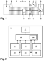
- Fig. 1 shows schematically a ring spinning machine 1 according to the present invention, which has a plurality of juxtaposed spinning units 2.
- the spinning units 2 are located in a longitudinal direction x of the ring spinning machine 1 between a head 31 and a foot 32.
- Head 3 1 and foot 3 2 of the ring spinning machine 1 may include bearings, drives, control, etc., which are necessary for the operation of the machine.
- each spinning unit 2 consists of a roving bobbin 4, which is arranged above a drafting device 5, and on which a roving 6 is wound.
- the roving 6 runs from the roving bobbin 4 via the drafting device 5, where it is stretched, to then be guided to a yarn forming element via a yarn guide.
- a circumferential ring winds the finished yarn on a cops 7.
- the cops 7 is placed on a spindle 8.
- a service robot 9 moves, which drives in the event of a yarn breakage to a corresponding spinning station 1 and automatically fixes the yarn breakage.
- the individual spinning unit 2 can be equipped with spindle monitors or other sensors for monitoring the ring traveller in order to detect a yarn breakage. Alternatively or additionally, the spinning units 2 can be equipped with single spindle drives.
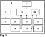
- Fig. 2 shows schematically a service robot 9 according to the invention.
- the service robot 9 comprises a main controller 10 and a memory 100, which can be part of the main controller 10 or be separated from it.
- the main controller 10 controls the operation of the service robot 9 for automatically fixing yarn breakage.
- the service robot 9 comprises
- the main controller 10 controls the operation (indicated by arrows) of the yarn search device 11, the tube handling device 12, the traveller thread device 13, the yarn handling device 14, the travelling and positioning device 15, travelling and positioning device 15 and the spindle brake unit 16 according a predefined schema or program. All these parts of the service robot 9 use specific setting parameters during operation as seen in Tab. 1. According to the present invention, as well shown in Tab. 1 these setting parameters for the service robot depend on specific yarn characteristics and on characteristics of the spinning machine 1.
- Tab. 1 Setting for Setting Parameters depend on the yarn characteristics Parameters depend on the characteristics of the ring spinning machine Yarn Search Device 11 Negative suction pressure Spindle speed Belt speed Yarn count Max.
- Spindle Brake unit 16 Brake force Spindle speed Brake time
- Spindle type General settings Numbers of attempts Yarn count machine length (spindle no.)
- Spindle speed Service station machine side left / right Yarn count
- Mechanical settings like Ring-diameter, tube length, traveller weight, Service robot left / right Yarn type Traversing mechanism (changing device)
- each set A, B, C of setting parameters e, f, g is used by the service robot 9 for another spinning program and is necessary for the production of a different yarn or to run a different spinning program.
- the number of sets A, B, C and parameters e, f, g is given by way of example only. It will depend on the operation of the service robot 9 and the spinning machine 1.
- initial configuration e.g. with delivery of the service robot 9, during a maintenance or when updating the software of the service robot 9 over the internet from server 50
- an operator chooses at the display 17 or a display 21 of the spinning machine a specific yarn to be produced (or a specific spinning program defining the yarn).
- one of the different sets A, B, C of setting parameters e, f, g is applied to the service robot 9 for the use during the service operation of the service robot 9.
- the chosen setting parameters are not fixed, but could be adapted.
- the service operation continues then with the adapted parameters.
- Preferred parameters for adapting are the setting parameters of the yarn search device 11, the tube handling device 12 and the traveller thread device 13 as given in Tab. 1.
- the controller 10 can be continuously or discontinuously monitor the success rate and the energy consumption of the service robot 9 to form a statistic.
- the controller 10 detects a decreasing success rate of the piecing process of the service robot 9, the controller 10 starts adapting the mentioned parameters. Based on a strategy on the influence of the parameter to increase the success rate the controller 10 will change these parameters in a first priority (e.g. suction pressure of yarn search device). The controller 10 sets these parameters in relation to the attempt of piecing, e.g. the statistic shows that a higher suction pressure of yarn search device increases the success rate for the second or any further attempt.
- a first priority e.g. suction pressure of yarn search device
- the controller 10 could adapt parameters which have an influence on the energy consumption by keeping the same level of success rate. If the success rate is decreasing due to adapted parameters having an influence on the energy consumption, the controller 10 could again adapt parameters for having a better success rate. Success rate and/or energy consumption of the service robot 9 or statistics of it can as well be displayed at display 17, display 21 or at a dashboard of the spinning mil (not shown).
- Fig. 4 shows schematically a system for connecting a spinning machine 1 to a server 50 over a network such as the internet 40.
- Server 50 comprises a database 51 with different sets A, B, C of setting parameters e, f, g for the service robot 9 as seen in Fig. 3 , which setting parameters e, f, g depend on yarn characteristics and characteristics of a spinning machine as giving in Tab. 1.
- the spinning machine 1 having in this example a plurality of service robots 9, which move along both side of the ring spinning machine 1. Depending on the length of the spinning machine 1, one side of the spinning machine 1 can as well be served by two or more service robots 9.
- the spinning machine 1 comprises a main controller 20 and a memory 200, which can be part of the main controller 20 or be separated from it.
- the main controller 20 controls the overall operation of the spinning machine 1 for production of the yarn as well as the service robots 9 (indicated in Fig. 2 by arrows).
- An operational control system 30 controls besides the spinning machine 1 other spinning machines of a spinning mil (not shown) and collects operational data from the spinning mil for displaying and analysis.
Landscapes
- Engineering & Computer Science (AREA)
- Mechanical Engineering (AREA)
- Textile Engineering (AREA)
- Spinning Or Twisting Of Yarns (AREA)
Claims (15)
- Procédé de fonctionnement d'un robot de service (9) d'un métier à filer continu à anneaux (1), qui est déplaçable le long d'une rangée d'unités de filage (2) du métier à filer continu à anneaux (1), chaque unité de filage (2) comprenant une broche (8), dans lequel le robot de service (9) peut être arrêté au niveau d'une unité de filage (2) spécifique afin de mettre en œuvre une opération de service au niveau de l'unité de filage (2) ; le procédé comprenant les étapes consistant à• stocker dans une mémoire (100, 200) différents ensembles (A, B, C) de paramètres de réglage (e, f, g) pour le robot de service (9), ces paramètres de réglage (e, f, g) dépendant de caractéristiques de fil et de caractéristiques du métier à filer continu à anneaux (1) ;• choisir un fil spécifique à produire sur le métier à filer (1) ;• appliquer l'un des ensembles (A, B, C) de paramètres de réglage (e, f, g) au robot de service (9) selon le fil choisi à produire et le métier à filer continu à anneaux (1) pour utilisation pendant l'opération de service ; caractérisé par les étapes consistant à• surveiller un taux de réussite et une consommation d'énergie du robot de service (9) et• changer au moins un paramètre de réglage (e, f, g) de l'ensemble (A, B, C) appliqué de paramètres (e, f, g) en dépendance du taux de réussite et/ou de la consommation d'énergie.
- Procédé selon la revendication 1, caractérisé par l'étape consistant à entrer par un opérateur au niveau du robot de service (9) ou du métier à filer continu à anneaux (1) le fil à produire et/ou un programme de filage définissant au moins le fil.
- Procédé selon l'une quelconque des revendications précédentes,
caractérisé par l'étape consistant à afficher des statistiques de taux de réussite et/ou de consommation d'énergie du robot de service. - Procédé selon l'une quelconque des revendications précédentes, caractérisé par l'étape consistant à transférer le taux de réussite et/ou la consommation d'énergie du robot de service (9) et l'ensemble (A, B, C) appliqué de paramètres (e, f, g) à un serveur internet (50).
- Procédé selon l'une quelconque des revendications précédentes, caractérisé par l'étape consistant à stocker différents ensembles (A, B, C) de paramètres de réglage (e, f, g) permettant de régler l'un ou une pluralité parmi• pression négative, vitesse et direction de courroie, temps de recherche et/ou pression de contact max de dispositif de recherche de fil d'un dispositif de recherche de fil du robot de service (9) ;• vitesse de rotation, temps de rotation et/ou direction de rotation d'un dispositif de manipulation de tube du robot de service (9) ;• pression d'air et/ou temps pour une impulsion d'air sous pression d'un dispositif de guidage de fil par curseur mobile du robot de service (9) ;• temps de raccordement, vitesse de déplacement et/ou pression d'aspiration d'un dispositif de manipulation de fil du robot de service (9) ;• vitesse minimale et maximale et/ou temps pour se déplacer à une position de parcage d'un dispositif de déplacement et de positionnement du robot de service (9) ;• force de freinage et/ou temps de freinage d'une unité de freinage de broche du robot de service (9) ;• réglages généraux du robot de service (9) ; et• réglages d'un poste de service du robot de service (9) ; et• nombre maximal d'opérations de raccordement renouvelé à l'aide d'un fil auxiliaire d'un dispositif de raccordement de fil auxiliaire du robot de service (9) par bobine ;• nombre maximal d'opérations de raccordement renouvelé à l'aide d'un fil auxiliaire d'un dispositif de raccordement de fil auxiliaire du robot de service (9) par lot de production du métier à filer continu à anneaux (1).
- Procédé selon l'une quelconque des revendications précédentes,
caractérisé par l'étape consistant à stocker différents ensembles (A, B, C) de paramètres de réglage (e, f, g) ces paramètres (e, f, g) dépendant de l'un ou d'une pluralité parmi nombre de fils, type de fil, torsion S/Z, en guise de caractéristiques de fil. - Procédé selon l'une quelconque des revendications précédentes,
caractérisé en ce que les paramètres de réglage (e, f, g) dépendent de l'une ou d'une pluralité de caractéristiques du métier à filer continu à anneaux (1) :• une vitesse de broche ou un type de broche ;• un type de curseur mobile ;• un diamètre d'anneau ;• un va-et-vient ;• une longueur de tube ;• une longueur du métier à filer continu à anneaux (1) ;• un type du métier à filer continu à anneaux (1) ;• un côté du métier à filer continu à anneaux (1) ; et• l'existence d'un dispositif d'arrêt de mèche. - Procédé selon l'une quelconque des revendications précédentes,
caractérisé par l'étape consistant à entrer par un opérateur au niveau du robot de service ou du métier à filer continu à anneaux l'un ou une pluralité parmi• le temps de recherche max d'un dispositif de recherche de fil du robot de service (9) avant qu'un dispositif de raccordement de fil auxiliaire du robot de service (9) ne mette en œuvre une opération de raccordement renouvelé à l'aide d'un fil auxiliaire ;• le nombre maximal d'opérations de raccordement renouvelé à l'aide d'un fil auxiliaire d'un dispositif de raccordement de fil auxiliaire du robot de service (9) par bobine par lot de production ;• le nombre maximal d'opérations de raccordement renouvelé à l'aide d'un fil auxiliaire d'un dispositif de raccordement de fil auxiliaire du robot de service (9) par lot de production du métier à filer continu à anneaux (1). - Procédé selon l'une quelconque des revendications précédentes, caractérisé par l'étape consistant à charger des ensembles (A, B, C) prédéfinis de paramètres de réglage (e, f, g) dans la mémoire (100, 200).
- Procédé selon l'une quelconque des revendications précédentes, caractérisé par l'étape consistant à télécharger ou à téléverser des ensembles (A, B, C) de paramètres de réglage (e, f, g) à partir d'un ou vers un serveur (50) sur internet (40) vers le ou à partir du robot de service (9).
- Procédé selon l'une quelconque des revendications précédentes, caractérisé par l'étape consistant à remplacer le robot de service (9) et à transférer l'ensemble (A, B, C) appliqué de paramètres de réglage (e, f, g) vers le robot de service (9) remplacé.
- Procédé selon l'une quelconque des revendications précédentes, caractérisé par l'étape consistant à• transférer l'ensemble (A, B, C) appliqué de paramètres de réglage (e, f, g) à partir du robot de service (9) vers un dispositif de commande principal (20) du métier à filer continu à anneaux (1) ; et• synchroniser tous les robots de service (9) connectés au métier à filer continu à anneaux (1) avec les paramètres de réglage (e, f, g) transférés.
- Métier à filer continu à anneaux (1) permettant de mettre en œuvre l'une des revendications de procédé 1 à 12 avec un robot de service (9), qui est déplaçable le long d'une rangée d'unités de filage (2) du métier à filer continu à anneaux (1), chaque unité de filage (2) comprenant une broche (8), dans lequel le robot de service (9) peut être arrêté au niveau d'une unité de filage (2) spécifique afin de mettre en œuvre une opération de service au niveau de l'unité de filage (2) ; comprenant• une mémoire (100, 200) permettant de stocker différents ensembles (A, B, C) de paramètres de réglage (e, f, g) pour le robot de service (9), ces paramètres de réglage (e, f, g) dépendant de caractéristiques de fil et de caractéristiques du métier à filer continu à anneaux (1) ;• un affichage (17, 21) permettant de choisir un fil spécifique à produire sur le métier à filer continu à anneaux (1) ;• un dispositif de commande (10, 20) permettant d'appliquer l'un des ensembles (A, B, C) de paramètres de réglage (e, f, g) au robot de service (9) selon le fil choisi à produire et le métier à filer continu à anneaux (1) pour utilisation pendant l'opération de service caractérisé en ce que le dispositif de commande (10, 20) est conçu pour surveiller un taux de réussite et une consommation d'énergie du robot de service (9) et pour changer au moins un paramètre de réglage (e, f, g) de l'ensemble (A, B, C) appliqué de paramètres (e, f, g) en dépendance du taux de réussite et/ou de la consommation d'énergie.
- Métier à filer continu à anneaux (1) selon la revendication 13, caractérisé par une interface permettant de télécharger ou de téléverser des ensembles (A, B, C) de paramètres de réglage (e, f, g) à partir d'un ou vers un serveur (50) sur internet (40) vers le ou à partir du robot de service (9).
- Métier à filer continu à anneaux (1) selon l'une quelconque des revendications 13 à 14 précédentes, caractérisé en ce que les paramètres de réglage (e, f, g) comprennent des paramètres (A, B, C) permettant de régler l'un ou une pluralité parmiun dispositif de recherche de fil du robot de service (9) ;un dispositif de manipulation de tube du robot de service (9) ;un dispositif de guidage de fil par curseur mobile du robot de service (9) ;un dispositif de manipulation de fil du robot de service (9) ;une position de parcage d'un dispositif de déplacement et de positionnement du robot de service (9) ;une unité de freinage de broche du robot de service (9) ;un dispositif de raccordement de fil auxiliaire du robot de service (9) ;des réglages généraux du robot de service (9) ; et/ou des réglages d'un poste de service du robot de service (9).
Applications Claiming Priority (2)
| Application Number | Priority Date | Filing Date | Title |
|---|---|---|---|
| CH11222018 | 2018-09-19 | ||
| PCT/IB2019/055152 WO2020058775A1 (fr) | 2018-09-19 | 2019-06-19 | Procédé de fonctionnement d'un robot d'entretien d'un métier à filer à anneaux |
Publications (2)
| Publication Number | Publication Date |
|---|---|
| EP3853400A1 EP3853400A1 (fr) | 2021-07-28 |
| EP3853400B1 true EP3853400B1 (fr) | 2025-04-23 |
Family
ID=67847752
Family Applications (1)
| Application Number | Title | Priority Date | Filing Date |
|---|---|---|---|
| EP19762841.5A Active EP3853400B1 (fr) | 2018-09-19 | 2019-06-19 | Procédé de fonctionnement d'un robot d'un métier à filer à anneaux |
Country Status (4)
| Country | Link |
|---|---|
| EP (1) | EP3853400B1 (fr) |
| CN (1) | CN112703279A (fr) |
| ES (1) | ES3035938T3 (fr) |
| WO (1) | WO2020058775A1 (fr) |
Families Citing this family (1)
| Publication number | Priority date | Publication date | Assignee | Title |
|---|---|---|---|---|
| CH718245A1 (de) * | 2021-01-06 | 2022-07-15 | Rieter Ag Maschf | Verfahren zum Ansetzen und Ansetzvorrichtung an einer Ringspinnmaschine. |
Citations (1)
| Publication number | Priority date | Publication date | Assignee | Title |
|---|---|---|---|---|
| DE3921202A1 (de) * | 1989-06-28 | 1991-01-03 | Zinser Textilmaschinen Gmbh | Verfahren und vorrichtung zur funktionsgerechten positionierung einer fadensuchduese |
Family Cites Families (19)
| Publication number | Priority date | Publication date | Assignee | Title |
|---|---|---|---|---|
| US3540200A (en) | 1967-08-19 | 1970-11-17 | Toyo Boseki | Automatic yarn piecing apparatus for ring spinning frame or the like |
| EP0391110B1 (fr) | 1989-03-22 | 1995-10-18 | Maschinenfabrik Rieter Ag | Procédé et dispositif pour enfiler un fil partiellement enroulé sur une bobine de fil dans un métier à filer |
| CS136690A2 (en) | 1989-03-23 | 1991-12-17 | Rieter Ag Maschf | Method of ring spinning frame operation and service robot for this method realization |
| DE4039486A1 (de) | 1990-12-11 | 1992-06-17 | Zinser Textilmaschinen Gmbh | Verfahren und vorrichtung zum selbsttaetigen fadenansetzen an einer spinnereimaschine |
| DE4119382A1 (de) * | 1991-06-12 | 1992-12-17 | Zinser Textilmaschinen Gmbh | Verfahren und vorrichtung zum suchen eines fadenendes oder aufwerfen eines hilfsfadens an einem kops bzw. an einen kops oder eine leere huelse |
| DE4205165C1 (en) * | 1992-02-20 | 1993-06-24 | Zinser Textilmaschinen Gmbh, 7333 Ebersbach, De | Ring spinning frame - has electronic circuits in service unit to automatic ally piece up rovings to spun yarn with progressively improved performance |
| JP3079833B2 (ja) * | 1993-05-10 | 2000-08-21 | 株式会社豊田自動織機製作所 | 粗糸替機及び粗糸替システム |
| DE4431810B4 (de) | 1994-09-07 | 2006-07-06 | Rieter Ingolstadt Spinnereimaschinenbau Ag | Einstellung der Parameter für optimale Ansetzvorgänge einer Ansetzvorrichtung bei Partiewechsel an einer Rotorspinnmaschine |
| DE10142976A1 (de) | 2001-09-01 | 2003-03-20 | Rieter Ingolstadt Spinnerei | Textilanlage mit einer Steuereinrichtung zur Bereitstellung partiebezogener Betriebsdaten |
| EP2017376A1 (fr) * | 2007-07-16 | 2009-01-21 | Maschinenfabrik Rieter Ag | Procédé destiné au fonctionnement d'un métier à tisser |
| DE102013008107A1 (de) * | 2013-05-11 | 2014-11-13 | Saurer Germany Gmbh & Co. Kg | Verfahren zum Betreiben einer Offenend-Rotorspinnmaschine |
| DE102014016785A1 (de) * | 2014-11-13 | 2016-05-19 | Saurer Germany Gmbh & Co. Kg | Verfahren zum Betreiben einer Textilmaschine und Textilmaschine |
| DE102015014177A1 (de) * | 2015-11-03 | 2017-05-04 | Saurer Germany Gmbh & Co. Kg | Textilmaschine mit einer Vielzahl nebeneinander angeordneter Arbeitsstellen |
| JP2018066084A (ja) * | 2016-10-19 | 2018-04-26 | 村田機械株式会社 | 紡績機械管理システム及び管理方法 |
| CZ2016746A3 (cs) | 2016-11-30 | 2018-06-13 | Rieter Cz S.R.O. | Způsob vyhledání konce příze na cívce textilního stroje vyrábějícího nebo zpracovávajícího přízi a zařízení k jeho provádění |
| CZ201834A3 (cs) | 2018-01-24 | 2019-07-31 | Rieter Cz S.R.O. | Způsob navlečení konce příze do běžce na prstenci s korunkou na spřádacím místě prstencového spřádacího stroje a zařízení k jeho provádění |
| CZ201847A3 (cs) | 2018-01-31 | 2019-08-07 | Rieter Cz S.R.O. | Zařízení pro manipulaci s cívkou, způsob dopravy cívky, obslužné zařízení prstencového spřádacího stroje a prstencový spřádací stroj |
| CZ307898B6 (cs) | 2018-01-31 | 2019-07-31 | Rieter Cz S.R.O. | Zařízení pro manipulaci s koncem příze na spřádacím místě prstencového spřádacího stroje, způsob manipulace s koncem příze a prstencový spřádací stroj |
| CZ308004B6 (cs) | 2018-01-31 | 2019-10-16 | Rieter Cz S.R.O. | Způsob polohování obslužného zařízení spřádacího stroje, zařízení k jeho provádění a spřádací stroj |
-
2019
- 2019-06-19 EP EP19762841.5A patent/EP3853400B1/fr active Active
- 2019-06-19 ES ES19762841T patent/ES3035938T3/es active Active
- 2019-06-19 WO PCT/IB2019/055152 patent/WO2020058775A1/fr not_active Ceased
- 2019-06-19 CN CN201980061197.0A patent/CN112703279A/zh active Pending
Patent Citations (1)
| Publication number | Priority date | Publication date | Assignee | Title |
|---|---|---|---|---|
| DE3921202A1 (de) * | 1989-06-28 | 1991-01-03 | Zinser Textilmaschinen Gmbh | Verfahren und vorrichtung zur funktionsgerechten positionierung einer fadensuchduese |
Also Published As
| Publication number | Publication date |
|---|---|
| ES3035938T3 (en) | 2025-09-11 |
| WO2020058775A1 (fr) | 2020-03-26 |
| EP3853400A1 (fr) | 2021-07-28 |
| CN112703279A (zh) | 2021-04-23 |
Similar Documents
| Publication | Publication Date | Title |
|---|---|---|
| US10414623B2 (en) | Method for operating a textile machine with work stations having their own handling elements for piecing of a thread, and a textile machine with own work stations having their own handling elements | |
| US9708151B2 (en) | Bobbin winding machine | |
| CN110952181B (zh) | 用于操作环锭纺纱机的方法 | |
| USRE34170E (en) | Spinning unit piecing process for producing feed spools | |
| CN104816981A (zh) | 筒管安装装置以及纱线卷取机 | |
| EP2749517B1 (fr) | Fileuse | |
| CN111433397A (zh) | 用于运行用来对前面的环锭纺纱机的管纱进行重绕的络筒机的方法 | |
| CN100507106C (zh) | 用于自由端纺纱机的维护小车 | |
| CN105764823B (zh) | 变形机和用于操作变形机的卷绕站的方法 | |
| JP2016194187A (ja) | 少なくとも1つのリング精紡機と少なくとも1つの巻取り機とから成る複合システムを運転する方法並びに複合システム | |
| CN110578192B (zh) | 用于影响环锭纺纱筒管的缠绕状态的方法和装置 | |
| EP3438334B1 (fr) | Métier à filer pneumatique et procédé de commande d'affichage | |
| EP3853400A1 (fr) | Procédé de fonctionnement d'un robot d'entretien d'un métier à filer à anneaux | |
| JP2016108156A (ja) | 紡績コップを製造しかつさらに処理する方法 | |
| US5170617A (en) | Method and apparatus for producing packages | |
| EP2080825A2 (fr) | Machine à enrouleur de fils intégré | |
| CN114717697B (zh) | 接头方法和接头设备 | |
| CN104828646A (zh) | 落纱装置以及具备该落纱装置的纱线卷取机 | |
| EP3643819B1 (fr) | Agencement de prélèvement de fil d'un métier à filer à anneaux et procédé associé | |
| CN113355773A (zh) | 纺纱或绕线机的操作方法以及纺纱或绕线机 | |
| EP0387009A2 (fr) | Procédé et dispositif pour rattacher des fils textiles | |
| JP2017089090A (ja) | エアジェット紡績機上の紡績工程を再開させるためワークステーションを準備する方法、及びその方法を実施するためのエアジェット紡績機 | |
| CZ290275B6 (cs) | Způsob spotřebování smyčky příze po zapředení příze na rotorovém dopřádacím stroji | |
| JP2021188180A (ja) | 紡績機、紡績方法、及び糸巻取機 | |
| JP2006241616A (ja) | 空気紡績機および紡績システム |
Legal Events
| Date | Code | Title | Description |
|---|---|---|---|
| STAA | Information on the status of an ep patent application or granted ep patent |
Free format text: STATUS: UNKNOWN |
|
| STAA | Information on the status of an ep patent application or granted ep patent |
Free format text: STATUS: THE INTERNATIONAL PUBLICATION HAS BEEN MADE |
|
| TPAC | Observations filed by third parties |
Free format text: ORIGINAL CODE: EPIDOSNTIPA |
|
| PUAI | Public reference made under article 153(3) epc to a published international application that has entered the european phase |
Free format text: ORIGINAL CODE: 0009012 |
|
| STAA | Information on the status of an ep patent application or granted ep patent |
Free format text: STATUS: REQUEST FOR EXAMINATION WAS MADE |
|
| 17P | Request for examination filed |
Effective date: 20210308 |
|
| AK | Designated contracting states |
Kind code of ref document: A1 Designated state(s): AL AT BE BG CH CY CZ DE DK EE ES FI FR GB GR HR HU IE IS IT LI LT LU LV MC MK MT NL NO PL PT RO RS SE SI SK SM TR |
|
| DAV | Request for validation of the european patent (deleted) | ||
| DAX | Request for extension of the european patent (deleted) | ||
| STAA | Information on the status of an ep patent application or granted ep patent |
Free format text: STATUS: EXAMINATION IS IN PROGRESS |
|
| 17Q | First examination report despatched |
Effective date: 20230313 |
|
| P01 | Opt-out of the competence of the unified patent court (upc) registered |
Effective date: 20230519 |
|
| RAP3 | Party data changed (applicant data changed or rights of an application transferred) |
Owner name: RIETER AG |
|
| GRAP | Despatch of communication of intention to grant a patent |
Free format text: ORIGINAL CODE: EPIDOSNIGR1 |
|
| STAA | Information on the status of an ep patent application or granted ep patent |
Free format text: STATUS: GRANT OF PATENT IS INTENDED |
|
| INTG | Intention to grant announced |
Effective date: 20241121 |
|
| GRAS | Grant fee paid |
Free format text: ORIGINAL CODE: EPIDOSNIGR3 |
|
| GRAA | (expected) grant |
Free format text: ORIGINAL CODE: 0009210 |
|
| STAA | Information on the status of an ep patent application or granted ep patent |
Free format text: STATUS: THE PATENT HAS BEEN GRANTED |
|
| AK | Designated contracting states |
Kind code of ref document: B1 Designated state(s): AL AT BE BG CH CY CZ DE DK EE ES FI FR GB GR HR HU IE IS IT LI LT LU LV MC MK MT NL NO PL PT RO RS SE SI SK SM TR |
|
| REG | Reference to a national code |
Ref country code: GB Ref legal event code: FG4D |
|
| REG | Reference to a national code |
Ref country code: CH Ref legal event code: EP |
|
| REG | Reference to a national code |
Ref country code: DE Ref legal event code: R096 Ref document number: 602019069020 Country of ref document: DE |
|
| REG | Reference to a national code |
Ref country code: IE Ref legal event code: FG4D |
|
| PGFP | Annual fee paid to national office [announced via postgrant information from national office to epo] |
Ref country code: DE Payment date: 20250618 Year of fee payment: 7 |
|
| REG | Reference to a national code |
Ref country code: NL Ref legal event code: MP Effective date: 20250423 |
|
| REG | Reference to a national code |
Ref country code: ES Ref legal event code: FG2A Ref document number: 3035938 Country of ref document: ES Kind code of ref document: T3 Effective date: 20250911 |
|
| PG25 | Lapsed in a contracting state [announced via postgrant information from national office to epo] |
Ref country code: NL Free format text: LAPSE BECAUSE OF FAILURE TO SUBMIT A TRANSLATION OF THE DESCRIPTION OR TO PAY THE FEE WITHIN THE PRESCRIBED TIME-LIMIT Effective date: 20250423 |
|
| REG | Reference to a national code |
Ref country code: AT Ref legal event code: MK05 Ref document number: 1787839 Country of ref document: AT Kind code of ref document: T Effective date: 20250423 |
|
| PG25 | Lapsed in a contracting state [announced via postgrant information from national office to epo] |
Ref country code: FI Free format text: LAPSE BECAUSE OF FAILURE TO SUBMIT A TRANSLATION OF THE DESCRIPTION OR TO PAY THE FEE WITHIN THE PRESCRIBED TIME-LIMIT Effective date: 20250423 Ref country code: PT Free format text: LAPSE BECAUSE OF FAILURE TO SUBMIT A TRANSLATION OF THE DESCRIPTION OR TO PAY THE FEE WITHIN THE PRESCRIBED TIME-LIMIT Effective date: 20250825 |
|
| PGFP | Annual fee paid to national office [announced via postgrant information from national office to epo] |
Ref country code: ES Payment date: 20250718 Year of fee payment: 7 |
|
| REG | Reference to a national code |
Ref country code: LT Ref legal event code: MG9D |
|
| PG25 | Lapsed in a contracting state [announced via postgrant information from national office to epo] |
Ref country code: NO Free format text: LAPSE BECAUSE OF FAILURE TO SUBMIT A TRANSLATION OF THE DESCRIPTION OR TO PAY THE FEE WITHIN THE PRESCRIBED TIME-LIMIT Effective date: 20250723 Ref country code: GR Free format text: LAPSE BECAUSE OF FAILURE TO SUBMIT A TRANSLATION OF THE DESCRIPTION OR TO PAY THE FEE WITHIN THE PRESCRIBED TIME-LIMIT Effective date: 20250724 |
|
| PG25 | Lapsed in a contracting state [announced via postgrant information from national office to epo] |
Ref country code: PL Free format text: LAPSE BECAUSE OF FAILURE TO SUBMIT A TRANSLATION OF THE DESCRIPTION OR TO PAY THE FEE WITHIN THE PRESCRIBED TIME-LIMIT Effective date: 20250423 |
|
| PGFP | Annual fee paid to national office [announced via postgrant information from national office to epo] |
Ref country code: TR Payment date: 20250718 Year of fee payment: 7 |
|
| PG25 | Lapsed in a contracting state [announced via postgrant information from national office to epo] |
Ref country code: BG Free format text: LAPSE BECAUSE OF FAILURE TO SUBMIT A TRANSLATION OF THE DESCRIPTION OR TO PAY THE FEE WITHIN THE PRESCRIBED TIME-LIMIT Effective date: 20250423 |
|
| PG25 | Lapsed in a contracting state [announced via postgrant information from national office to epo] |
Ref country code: HR Free format text: LAPSE BECAUSE OF FAILURE TO SUBMIT A TRANSLATION OF THE DESCRIPTION OR TO PAY THE FEE WITHIN THE PRESCRIBED TIME-LIMIT Effective date: 20250423 |
|
| PG25 | Lapsed in a contracting state [announced via postgrant information from national office to epo] |
Ref country code: AT Free format text: LAPSE BECAUSE OF FAILURE TO SUBMIT A TRANSLATION OF THE DESCRIPTION OR TO PAY THE FEE WITHIN THE PRESCRIBED TIME-LIMIT Effective date: 20250423 |
|
| PG25 | Lapsed in a contracting state [announced via postgrant information from national office to epo] |
Ref country code: RS Free format text: LAPSE BECAUSE OF FAILURE TO SUBMIT A TRANSLATION OF THE DESCRIPTION OR TO PAY THE FEE WITHIN THE PRESCRIBED TIME-LIMIT Effective date: 20250723 |
|
| PG25 | Lapsed in a contracting state [announced via postgrant information from national office to epo] |
Ref country code: IS Free format text: LAPSE BECAUSE OF FAILURE TO SUBMIT A TRANSLATION OF THE DESCRIPTION OR TO PAY THE FEE WITHIN THE PRESCRIBED TIME-LIMIT Effective date: 20250823 |
|
| PG25 | Lapsed in a contracting state [announced via postgrant information from national office to epo] |
Ref country code: LV Free format text: LAPSE BECAUSE OF FAILURE TO SUBMIT A TRANSLATION OF THE DESCRIPTION OR TO PAY THE FEE WITHIN THE PRESCRIBED TIME-LIMIT Effective date: 20250423 |
|
| PG25 | Lapsed in a contracting state [announced via postgrant information from national office to epo] |
Ref country code: DK Free format text: LAPSE BECAUSE OF FAILURE TO SUBMIT A TRANSLATION OF THE DESCRIPTION OR TO PAY THE FEE WITHIN THE PRESCRIBED TIME-LIMIT Effective date: 20250423 Ref country code: SM Free format text: LAPSE BECAUSE OF FAILURE TO SUBMIT A TRANSLATION OF THE DESCRIPTION OR TO PAY THE FEE WITHIN THE PRESCRIBED TIME-LIMIT Effective date: 20250423 |
|
| PG25 | Lapsed in a contracting state [announced via postgrant information from national office to epo] |
Ref country code: CZ Free format text: LAPSE BECAUSE OF FAILURE TO SUBMIT A TRANSLATION OF THE DESCRIPTION OR TO PAY THE FEE WITHIN THE PRESCRIBED TIME-LIMIT Effective date: 20250423 |
|
| PG25 | Lapsed in a contracting state [announced via postgrant information from national office to epo] |
Ref country code: EE Free format text: LAPSE BECAUSE OF FAILURE TO SUBMIT A TRANSLATION OF THE DESCRIPTION OR TO PAY THE FEE WITHIN THE PRESCRIBED TIME-LIMIT Effective date: 20250423 |
|
| REG | Reference to a national code |
Ref country code: DE Ref legal event code: R097 Ref document number: 602019069020 Country of ref document: DE |
|
| PG25 | Lapsed in a contracting state [announced via postgrant information from national office to epo] |
Ref country code: RO Free format text: LAPSE BECAUSE OF FAILURE TO SUBMIT A TRANSLATION OF THE DESCRIPTION OR TO PAY THE FEE WITHIN THE PRESCRIBED TIME-LIMIT Effective date: 20250423 Ref country code: SK Free format text: LAPSE BECAUSE OF FAILURE TO SUBMIT A TRANSLATION OF THE DESCRIPTION OR TO PAY THE FEE WITHIN THE PRESCRIBED TIME-LIMIT Effective date: 20250423 |
|
| REG | Reference to a national code |
Ref country code: CH Ref legal event code: H13 Free format text: ST27 STATUS EVENT CODE: U-0-0-H10-H13 (AS PROVIDED BY THE NATIONAL OFFICE) Effective date: 20260127 |
|
| PG25 | Lapsed in a contracting state [announced via postgrant information from national office to epo] |
Ref country code: IT Free format text: LAPSE BECAUSE OF FAILURE TO SUBMIT A TRANSLATION OF THE DESCRIPTION OR TO PAY THE FEE WITHIN THE PRESCRIBED TIME-LIMIT Effective date: 20250423 |
|
| PG25 | Lapsed in a contracting state [announced via postgrant information from national office to epo] |
Ref country code: MC Free format text: LAPSE BECAUSE OF FAILURE TO SUBMIT A TRANSLATION OF THE DESCRIPTION OR TO PAY THE FEE WITHIN THE PRESCRIBED TIME-LIMIT Effective date: 20250423 |
|
| PG25 | Lapsed in a contracting state [announced via postgrant information from national office to epo] |
Ref country code: LU Free format text: LAPSE BECAUSE OF NON-PAYMENT OF DUE FEES Effective date: 20250619 |
|
| REG | Reference to a national code |
Ref country code: BE Ref legal event code: MM Effective date: 20250630 |
|
| PLBE | No opposition filed within time limit |
Free format text: ORIGINAL CODE: 0009261 |
|
| STAA | Information on the status of an ep patent application or granted ep patent |
Free format text: STATUS: NO OPPOSITION FILED WITHIN TIME LIMIT |
|
| REG | Reference to a national code |
Ref country code: CH Ref legal event code: L10 Free format text: ST27 STATUS EVENT CODE: U-0-0-L10-L00 (AS PROVIDED BY THE NATIONAL OFFICE) Effective date: 20260304 |
|
| GBPC | Gb: european patent ceased through non-payment of renewal fee |
Effective date: 20250723 |
|
| 26N | No opposition filed |
Effective date: 20260126 |
|
| PG25 | Lapsed in a contracting state [announced via postgrant information from national office to epo] |
Ref country code: GB Free format text: LAPSE BECAUSE OF NON-PAYMENT OF DUE FEES Effective date: 20250723 |
|
| PG25 | Lapsed in a contracting state [announced via postgrant information from national office to epo] |
Ref country code: IE Free format text: LAPSE BECAUSE OF NON-PAYMENT OF DUE FEES Effective date: 20250619 |
|
| PG25 | Lapsed in a contracting state [announced via postgrant information from national office to epo] |
Ref country code: BE Free format text: LAPSE BECAUSE OF NON-PAYMENT OF DUE FEES Effective date: 20250630 |
|
| PG25 | Lapsed in a contracting state [announced via postgrant information from national office to epo] |
Ref country code: FR Free format text: LAPSE BECAUSE OF NON-PAYMENT OF DUE FEES Effective date: 20250623 |
|
| PG25 | Lapsed in a contracting state [announced via postgrant information from national office to epo] |
Ref country code: CH Free format text: LAPSE BECAUSE OF NON-PAYMENT OF DUE FEES Effective date: 20250630 |