EP3853476B1 - Heating system and method for a jointed wind rotor turbine blade - Google Patents
Heating system and method for a jointed wind rotor turbine blade Download PDFInfo
- Publication number
- EP3853476B1 EP3853476B1 EP19778743.5A EP19778743A EP3853476B1 EP 3853476 B1 EP3853476 B1 EP 3853476B1 EP 19778743 A EP19778743 A EP 19778743A EP 3853476 B1 EP3853476 B1 EP 3853476B1
- Authority
- EP
- European Patent Office
- Prior art keywords
- blade
- blade segment
- heating system
- wind turbine
- segment
- Prior art date
- Legal status (The legal status is an assumption and is not a legal conclusion. Google has not performed a legal analysis and makes no representation as to the accuracy of the status listed.)
- Active
Links
Images




Classifications
-
- F—MECHANICAL ENGINEERING; LIGHTING; HEATING; WEAPONS; BLASTING
- F03—MACHINES OR ENGINES FOR LIQUIDS; WIND, SPRING, OR WEIGHT MOTORS; PRODUCING MECHANICAL POWER OR A REACTIVE PROPULSIVE THRUST, NOT OTHERWISE PROVIDED FOR
- F03D—WIND MOTORS
- F03D80/00—Details, components or accessories not provided for in groups F03D1/00 - F03D17/00
- F03D80/40—Ice detection; De-icing means
-
- F—MECHANICAL ENGINEERING; LIGHTING; HEATING; WEAPONS; BLASTING
- F03—MACHINES OR ENGINES FOR LIQUIDS; WIND, SPRING, OR WEIGHT MOTORS; PRODUCING MECHANICAL POWER OR A REACTIVE PROPULSIVE THRUST, NOT OTHERWISE PROVIDED FOR
- F03D—WIND MOTORS
- F03D1/00—Wind motors with rotation axis substantially parallel to the air flow entering the rotor
- F03D1/06—Rotors
- F03D1/065—Rotors characterised by their construction elements
- F03D1/0675—Rotors characterised by their construction elements of the blades
-
- F—MECHANICAL ENGINEERING; LIGHTING; HEATING; WEAPONS; BLASTING
- F03—MACHINES OR ENGINES FOR LIQUIDS; WIND, SPRING, OR WEIGHT MOTORS; PRODUCING MECHANICAL POWER OR A REACTIVE PROPULSIVE THRUST, NOT OTHERWISE PROVIDED FOR
- F03D—WIND MOTORS
- F03D80/00—Details, components or accessories not provided for in groups F03D1/00 - F03D17/00
- F03D80/60—Cooling or heating of wind motors
-
- F—MECHANICAL ENGINEERING; LIGHTING; HEATING; WEAPONS; BLASTING
- F05—INDEXING SCHEMES RELATING TO ENGINES OR PUMPS IN VARIOUS SUBCLASSES OF CLASSES F01-F04
- F05B—INDEXING SCHEME RELATING TO WIND, SPRING, WEIGHT, INERTIA OR LIKE MOTORS, TO MACHINES OR ENGINES FOR LIQUIDS COVERED BY SUBCLASSES F03B, F03D AND F03G
- F05B2240/00—Components
- F05B2240/20—Rotors
- F05B2240/30—Characteristics of rotor blades, i.e. of any element transforming dynamic fluid energy to or from rotational energy and being attached to a rotor
- F05B2240/302—Segmented or sectional blades
-
- F—MECHANICAL ENGINEERING; LIGHTING; HEATING; WEAPONS; BLASTING
- F05—INDEXING SCHEMES RELATING TO ENGINES OR PUMPS IN VARIOUS SUBCLASSES OF CLASSES F01-F04
- F05B—INDEXING SCHEME RELATING TO WIND, SPRING, WEIGHT, INERTIA OR LIKE MOTORS, TO MACHINES OR ENGINES FOR LIQUIDS COVERED BY SUBCLASSES F03B, F03D AND F03G
- F05B2260/00—Function
- F05B2260/20—Heat transfer, e.g. cooling
-
- F—MECHANICAL ENGINEERING; LIGHTING; HEATING; WEAPONS; BLASTING
- F05—INDEXING SCHEMES RELATING TO ENGINES OR PUMPS IN VARIOUS SUBCLASSES OF CLASSES F01-F04
- F05B—INDEXING SCHEME RELATING TO WIND, SPRING, WEIGHT, INERTIA OR LIKE MOTORS, TO MACHINES OR ENGINES FOR LIQUIDS COVERED BY SUBCLASSES F03B, F03D AND F03G
- F05B2260/00—Function
- F05B2260/60—Fluid transfer
-
- Y—GENERAL TAGGING OF NEW TECHNOLOGICAL DEVELOPMENTS; GENERAL TAGGING OF CROSS-SECTIONAL TECHNOLOGIES SPANNING OVER SEVERAL SECTIONS OF THE IPC; TECHNICAL SUBJECTS COVERED BY FORMER USPC CROSS-REFERENCE ART COLLECTIONS [XRACs] AND DIGESTS
- Y02—TECHNOLOGIES OR APPLICATIONS FOR MITIGATION OR ADAPTATION AGAINST CLIMATE CHANGE
- Y02E—REDUCTION OF GREENHOUSE GAS [GHG] EMISSIONS, RELATED TO ENERGY GENERATION, TRANSMISSION OR DISTRIBUTION
- Y02E10/00—Energy generation through renewable energy sources
- Y02E10/70—Wind energy
- Y02E10/72—Wind turbines with rotation axis in wind direction
Definitions
- the present subject matter relates generally to wind turbine rotor blades and, more particularly, to a jointed blade with a system for supplying heat to the tip blade segment separately from the root blade segment.
- Wind power is considered one of the cleanest, most environmentally friendly energy sources presently available, and wind turbines have gained increased attention in this regard.
- a modern wind turbine typically includes a tower, generator, gearbox, nacelle, and one or more rotor blades.
- the rotor blades capture kinetic energy from wind using known foil principles and transmit the kinetic energy through rotational energy to turn a shaft coupling the rotor blades to a gearbox, or if a gearbox is not used, directly to the generator.
- the generator then converts the mechanical energy to electrical energy that may be deployed to a utility grid.
- Wind turbine rotor blades generally include a body shell formed by two shell halves of a composite laminate material joined together along the leading and trailing edges of the blade.
- Internal support structure such as spar caps and shear webs, provide the structural properties to the blade (e.g., stiffness, buckling resistance, and strength) needed for the blade to withstand the bending moments and other loads exerted on the rotor blade during operation.
- wind turbines for wind power generation have significantly increased in size to achieve improvement in power generation efficiency and to increase the amount of power generation.
- wind turbine rotor blades have also significantly increased in size (e.g., up to 55 meters in length), resulting in difficulties in integral manufacture as well as conveyance and transport of the blades to a site.
- the industry is developing sectional wind turbine rotor blades wherein separate blade segments are manufactured and transported to a site for assembly into a complete blade (a "jointed" blade).
- the blade segments are joined together by a beam structure that extends span-wise from one blade segment into a receiving section of the other blade segment.
- a beam structure that extends span-wise from one blade segment into a receiving section of the other blade segment.
- the beam structure forms a portion of the internal support structure for the blade and includes a shear web connected with a suction side spar cap and a pressure side spar cap.
- Multiple bolt joints are used to connect the beam structure with the receiving section in the second blade segment, including a span-wise bolt on the end face of the beam and at least one chord-wise bolt through the beam structure spaced from the joint line between the blade segments.
- US Patent Publication No. 2011/0091326 describes a jointed blade wherein a first blade portion and a second blade portion extend in opposite directions from a joint.
- Each blade portion includes a spar section forming a structural member of the blade and running lengthways, wherein the first blade portion and the second blade portion are structurally connected by a spar bridge that joins the spar sections.
- the spar bridge may be an extension of one of the spar sections that is received in a receiving spar section of the other blade portion.
- This configuration also uses a threaded bolt extending from the end face of the spar to connect and tension the spar in the receiving spar section.
- Jointed wind turbine blades are, however, just as susceptible to icing as conventional blades. Under certain combinations of atmospheric conditions, the rotor blades can become covered with ice. For an operational wind turbine, ice buildup typically occurs on the leading edge of the blade, resulting in a modified airfoil shape and reduced lifting capability. As the ice layer becomes increasingly thick, weight is added to the airfoil, further reducing the lifting capability and the aerodynamic performance of the rotor blade. Ice shedding (the throwing off of ice as the blades rotate) can also be a safety issue, particularly for wind turbines located near residential areas. For wind turbines that are stopped or idling, ice will generally form uniformly over the entire surface of the blades, thereby necessitating deicing of the entire blade before the wind turbine can be placed back in operation.
- deicing wind turbine rotor blades which include preventing icing on the rotor blades when atmospheric conditions are favorable for ice formation.
- installing resistive heating wires or other electrical conductors onto the leading edge or other surfaces of the rotor blade is known.
- the Canadian patent CA 2228145 (counterpart to EP 0842360 B1 ) describes a system for deicing wind turbine rotor blades wherein a heated medium, which may be the air within the blade cavity, is channeled to internal cavities within the blade. The heated medium is directed from the blade root area into a cavity behind the leading edge of the blade, and then diverted at the blade tip into a cavity along the trailing edge of the blade and back to the root area.
- a fan with integrated heating elements is provided in the blade root to generate and maintain circulation of the heated medium.
- the chambers or cavities may be defined by reinforcement ribs that run parallel to the longitudinal axis of the blade.
- the tip section is the area of the blade most susceptible to icing, and heating systems have been devised to improve upon conventional systems (like that described in the CA 2228145 patent) wherein the warmest air is not directed to the tip of the blade first, but along the entire length of the leading edge before reaching the blade tip.
- US Patent Application Publication 2017/0314536 describes a deicing system for a wind turbine blade that utilizes an air heating system and an independently controlled electric heating system, wherein the electric system uses a heating element disposed on the leading edge of the blade adjacent to the blade tip.
- Jointed wind blades use various configurations of internal spar structure at the chord-wise j oint.
- This structure is an impediment to the flow of a heating medium into the tip segment, or a continuous heating element (e.g., a resistance mat or web) across the joint structure.
- an improved heating system is needed for a jointed blade that can adequately supply the tip segment of the blade with heat for deicing capability.
- US 2018 / 135 596 A1 relates to wind turbines and. more particularly, to a system for actuating wind turbine blades in the wind turbine.
- WO 2017 / 147 698 A2 describes a system and method for de-icing a wind turbine blade.
- the present disclosure is directed to a jointed wind turbine rotor blade with an improved heating system to deliver adequate deicing heat to the tip-end blade segment.
- the blade includes a first blade segment and a separate second blade segment.
- Each of the first and second blade segments has a pressure side shell member and a suction side shell member.
- the blade segments are joined together at a chord-wise joint that may be located closer to the tip end of the blade than the root end.
- the chord-wise joint may be at approximately 10 meters from the blade tip for a blade in excess of 50 meters in span-wise length.
- Internal joint structure joins the first and second blade segments across the chord-wise joint. This joint structure is not limited to a particular configuration, and various such structures are taught and known in the art.
- a first heating system is configured within the first blade segment, and a second heating system is configured within the second blade segment.
- the first blade segment is adjacent a root end of the wind turbine blade and the second blade segment is adjacent is adjacent a tip end of the wind turbine blade. It should be appreciated that the invention encompasses a wind turbine blade with multiple blade segments, wherein the chord-wise joint in accordance with aspects of the invention is provided between the multiple blade segments.
- a disconnectable coupling is configured between the first and second blade segments at the chord-wise joint, wherein the coupling is configured to supply power or a fluid medium from the first blade segment across the chord-wise joint for use by the second heating system in the second blade segment.
- the type of coupling will depend on the fluid medium or power requirements. For example, if the fluid medium is a heated liquid, various fluid couplings (including quick-disconnect couplings) are readily available for connecting a conduit in the first blade segment to a conduit in the second blade segment in order to convey the liquid from a heat source in the first blade segment to a heat exchanger in the second blade segment, and to return the liquid to the heat source in a closed-loop configuration.
- the couplings are connectable and disconnectable via any manner of suitable configurations.
- the couplings may include threaded fittings, pressure fittings, latching members, and so forth.
- Electrical couplings may include plug/socket connectors, pin connectors, terminal board connectors, and so forth.
- the first and second heating systems are independently controllable.
- a separate controller, heat source, motive means, and so forth, are provided in the first blade segment for each of the first and second heating systems.
- the first and second heating systems may be commonly controlled.
- the second heating system may be an operational extension of the first heating system and utilize the same heated medium, motive means, controller, and so forth.
- the internal joint structure includes a beam structure or member that extends span-wise from one of the blade segments into a receiving section formed in the other blade segment, wherein the coupling is configured with the beam structure and receiving section.
- the coupling may be configured across an external surface of the receiving section and an external surface of the beam structure at the chord-wise joint.
- the coupling may be configured through the receiving section and into the beam structure, wherein the power or fluid medium is conveyed through an internal conduit in the beam structure into the second blade segment.
- the internal joint structure may include one or more chord-wise walls separating the first and second blade segments at the chord-wise joint, wherein the coupling includes one or more disconnectable conduits for the power or fluid medium through the chord-wise walls.
- the first heating system may be a hot air heating system configured within the first blade segment
- the second heating system may be an electrical heating system configured within the second blade segment.
- the coupling may be a disconnectable electrical coupling between a power source in the first blade segment and a heating element in the second blade segment.
- Coupled may also encompass a power cord that is sufficiently long to extend from the power source in the first blade segment, through the joint structure, and connect to a heating element in the second blade segment.
- this "coupling” is disconnectable (can disconnect from the power source or the heating element) and serves to connect the power source in the first blade segment to the heating element in the second blade segment.
- the first heating system is a hot air heating system configured within the first blade segment
- the second heating system is a hot air heating system within the second blade segment.
- the coupling may include disconnectable ducting that supplies hot air across the chord-wise joint and into the second blade segment. This hot air may be supplied from the same source that supplies the first heating system, or may be from a separate dedicated source for the second blade segment.
- the internal joint structure may include a beam structure extending span-wise from one blade segment (e.g., the second blade segment) into a receiving section formed in the other blade segment (e.g., the first blade segment), where the beam structure and receiving section define a blockage that prevents the hot air from being conveyed into the second blade segment through the receiving section and beam structure.
- the ducting defines a bypass around the blockage and into the second blade segment.
- the beam structure may be an extension of the spar structure in the second blade segment, and the ducting may define a path for the hot air into a spar structure within the second blade segment.
- the jointed wind turbine blade may further include a lightning strike conductor that bridges the chordwise joint and connects blade tip receptors to a blade root grounding system, wherein the conductor includes an in-line disconnectable coupling at the chordwise joint.
- the present invention also encompasses a wind turbine that utilizes one or more of the jointed wind turbine blades embodied herein.
- the present invention encompasses a method for supplying heat for deicing in a jointed wind turbine rotor blade, wherein the blade includes a first blade segment adjacent a root end of the wind turbine rotor blade, a second blade segment adjacent a tip end of the wind turbine rotor blade, and internal joint structure joining the first and second blade segments across a chord-wise joint that separates the first and second blade segments.
- the method includes configuring a first heating system within the first blade segment, and configuring a second heating system within the second blade segment.
- a disconnectable coupling is configured between the first and second blade segments at the chord-wise joint.
- the method includes supplying power or a fluid medium from the first blade segment, through the coupling, and across the chord-wise joint for use by the second heating system in the second blade segment.
- the present subject matter is directed generally to jointed wind turbine rotor blades having an improved heating system for delivering adequate deicing capability to the tip-end blade segment.
- Fig. 1 is a side view of an exemplary wind turbine 10 that may use jointed wind turbine rotor blades in accordance with an embodiment of the present invention.
- the wind turbine 10 is a horizontal-axis wind turbine.
- the wind turbine 10 may be a vertical-axis wind turbine.
- the wind turbine 10 includes a tower 12 that extends from a support surface 14, a nacelle 16 mounted on the tower 12, a generator 18 positioned within the nacelle 16, a gearbox 20 coupled to the generator 18, and a rotor 22 that is rotationally coupled to the gearbox 20 with a rotor shaft 24.
- the rotor 22 includes a rotatable hub 26 and at least one rotor blade 28 coupled to and extending outward from the rotatable hub 26. As shown, the rotor blade 28 includes a blade tip 17 to a blade root 19.
- a jointed rotor blade 28 is depicted having a first blade segment 32 and a second blade segment 30 in accordance with aspects of the present technology.
- the jointed rotor blade 28 may include more than two blade segments.
- the first blade segment 32 and the second blade segment 30 extend in opposite directions from a chord-wise joint line 34.
- Each of the blade segments 30, 32 includes a pressure side shell member 31 and a suction side shell member 33.
- the first blade segment 32 and the second blade segment 30 are connected by an internal support structure 36 extending into both blade segments 30, 32 to facilitate joining of the blade segments 30, 32.
- the arrow 38 shows that the segmented rotor blade 28 in the illustrated example includes two blade segments 30, 32 and that these blade segments 30, 32 are joined by inserting the internal support structure 36 into the first blade segment 32.
- the second blade segment 30 is a tip-end blade segment, and the first blade segment 32 is a root-end blade segment. Joint structure is provided between the blade segments 30, 32.
- the invention is not limited to any particular type of joint structure.
- the second blade segment 30 includes a beam structure 40 that forms a portion of the internal support structure 36 and extends lengthways (e.g., span-wise) for structurally connecting with the internal support structure 36 in the first blade segment 32.
- the beam structure 40 may be integrally formed with the second blade segment 30 as an extension protruding from a spar section 42, thereby forming an extended spar section.
- the beam structure 40 includes at least one interconnecting web 44 (e.g., a shear web) connected with a suction side spar cap 46 and a pressure side spar cap 48.
- the beam structure 40 is formed as a box-type structure having opposite interconnecting webs 44.
- the second blade segment 30 may include one or more first bolt joints (also referred to as "pins") towards a first end 54 of the beam structure 40.
- a bolt 52 may be located on the end 54 of the beam structure 40 and oriented in a span-wise direction.
- the second blade segment 30 may also include a bolt joint slot 50 oriented in a chord-wise direction and located on the beam structure 40 at a distance E from the chord-wise joint 34 and a distance D to the end 54 of the beam structure 40.
- any combination of bolt tubes 52, 53 and bolt slots 50 may be configured between the beam structure 40 and a receiving section 60 ( Fig. 4 ) for the purpose of interconnecting the first 32 and second 30 blade segments.
- the internal support structure 36 includes a receiving section 60 extending lengthways (span-wise) within the first blade segment 32 for receiving the beam structure 40 of the second blade segment 30.
- the receiving section 60 includes multiple spar structure components 66 that extend lengthways for connecting with the beam structure 40 of the second blade segment 30 along a length of the receiving section 60.
- the receiving section 60 includes any combination of bolt slots 50 or bolts 52, 53 for interconnecting with corresponding bolts or slots of the beam structure 40.
- a bolt slot is configured in a distal end (away from the chord-wise joint 34) of the receiving section 60 for receipt of the bolt 52 provided on the end 54 of the beam structure 40.
- a jointed wind turbine blade 28 is shown with a first heating system 100 is configured within the first blade segment 32, and a second heating system 102 is configured within the second blade segment 30.
- the blade 28 includes a leading edge 74 and a trailing edge 76, as well as a root portion 19, and a tip portion 17.
- the blade 28 extends in a longitudinal, span-wise direction and, as is well known in the art, the upper shell member 31, 33 ( Fig. 4 ) are joined together at the leading edge 74 and trailing edge 76.
- the blade 28 includes an internal cavity in which various structural members, such as spar caps 46, 48 ( Fig. 3 ) and shear webs are configured.
- the construction and function of the internal structural components of the blade 28 are well known to those skilled in the art and need not be described in detail herein for an understanding and appreciation of the present invention.
- the first heating system 100 is a hot air heating system and includes any manner of structural members 70, such as webs 78, 80, walls, ducts, baffles, dampers, and so forth, disposed within the internal volume of the rotor blade 28.
- the webs 78, 80 may correspond to the shear webs.
- these members define a middle circulation channel that is common to a leading edge fluid circulation loop and a separate trailing edge fluid circulation loop, as indicated by the flow arrows in the figure.
- a single, continuous flow path could be established wherein the leading and trailing edge flows are serial (one-after-the-other) within the single loop.
- the first heating system 100 is disposed within the internal volume of the rotor blade 28 and is configured with the structural members 70 so as to direct a heated fluid medium (e.g., air) simultaneously through the leading edge and trailing edge fluid circulation loops.
- This system 100 may include any combination of air handling components, such a one or more fans, heater elements, dampers, ducts, and the like.
- the first heating system 100 includes a fan heater 82, which is intended to encompass any configuration of a fan and heating elements.
- the fan heater 66 may include a fan, one or more diffusers/ducts, and heating element within the same housing or separate housings.
- the heating elements may be resistive elements, and any other suitable heating element or system.
- the first heating system 100 is not limited to a single flow direction through the leading and trailing edge circulation loops.
- the fan heater 82 is disposed so as to direct a heated outflow airstream along the middle circulation channel to an area adjacent walls or other structure at the blade joint 34. From there, the outflow airstream is directed into separate return airstreams or legs of the respective circulation loops that flow along the leading edge 74 and the trailing edge 76 channels and back to the blade root 19, thereby establishing the counter-rotating flow path loops depicted in the figure.
- the second heating system 102 is an electrical system that includes a resistive heating element 122, such as a heating pad or mat, disposed within the internal volume of the second blade segment 30 along the leading edge 74.
- the heating element 122 is supplied with power from an electric power source 120 located in the blade root 19.
- the power source 120 may include a controller for controlling the second heating system 102 separate from the first heating system 100.
- a supply conduit or line 114 delivers power from the source 120 to the chord-wise joint 34.
- a disconnectable coupling 104 is configured between the first and second blade segments 32, 30 at the chord-wise joint 34, wherein the coupling 104 is configured to supply the electrical power (or a fluid medium in other embodiments) from the first blade segment 32 across the chord-wise joint 34 for use by the second heating system 102 in the second blade segment 30.
- the coupling 104 is specifically provided as an electrical coupling between the supply line 114 and the heating element 122.
- electrical couplings are well-known and may be used in the present system, such as plug/socket connectors, pin connectors, terminal board connectors, and so forth.
- Components of the coupling 104 may be housed in respective junction boxes 106 configured at the chord-wise joint 34 that structurally support and protect the coupling 104.
- the power supply line or conduit 114 may be configured as a power cord that is sufficiently long to extend from the power source 120 in the first blade segment 32, through the joint structure and chord-wise joint 34, and connect to the heating element 122 in the second blade segment 30.
- the type of coupling 104 will depend on the fluid medium or power requirements of the second heating system 102.
- the coupling 104 is preferably disconnectable with minimal tool requirements, and may be manually disconnectable.
- the coupling 104 may be a manually releasable quick-disconnect coupling 104.
- Fig. 5 also depicts that the jointed blade 28 may include a lightning strike conductor 150 that connects with a plurality of lightning receptors 152 disposed span-wise along the blade segments 32, 30 and embedded or otherwise incorporated in the shell components.
- the conductor 150 is connected to a blade root grounding system 154 that grounds the receptors 152, as is well-known to those skilled in the art and does not require a detailed explanation herein.
- a disconnectable coupling 156 is configured in-line with the conductor 159 at the chord-wise joint 34. This coupling 156 may be any manner of conventional quick-disconnect coupling specifically designed for electrical conduction lines.
- Fig. 6 depicts an embodiment wherein the second heating system 102 is configured as a heated liquid system wherein a heated liquid is conveyed from a heat source 120 in the root 19 through a supply conduit 114 to the liquid coupling 104 at the chord-wise joint 34.
- the liquid coupling 104 connects with a heat exchanger mat or pad 132 disposed within the second blade segment 30 along the leading edge 74. After passing through the heat exchanger mat 132, the cooled liquid is conveyed through the coupling 104 to a return conduit 115 in the first blade segment 32 in a closed-loop system.
- the liquid coupling 104 includes separate coupling components for the supply 114 and return 115 conduits, and may threaded fittings, pressure fittings, latching members, and so forth.
- Fig. 7 depicts an embodiment wherein the first heating system 100 is a hot air heating system configured within the first blade segment 32, and the second heating system 102 is a hot air heating system within the second blade segment 30.
- the coupling 104 may include disconnectable ducting that supplies hot air across the chord-wise joint34 and into a conduit, baffling, or other directional structure in the second blade segment 30. This hot air may be supplied from a separate dedicated source 134 and supply duct or channel 124 for the second blade segment 30.
- the second heating system 102 may be an operational extension of the first heating system 100 and utilize the same heated medium, motive means, controller, and so forth.
- the coupling 104 may be configured at the end of the central channel from the same source 82 that supplies the first heating system 100.
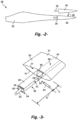
- the internal joint structure 36 includes a beam structure or member 40 that extends span-wise from one of the blade segments (in this case, the second blade segment 30) into a receiving section 60 formed in the other blade segment (in this case, the first blade segment 32), wherein the coupling 104 is configured with the beam structure 40 and receiving section 60.
- the joint structure 36 (particularly the end 54 of the beam 40 and wall 63 delimiting the receiver section 60) essentially defines a blockage 128 that prevents a heated medium, such as hot air, from being conveyed directly into the second blade segment 30 through the receiving section 60 and beam structure 40.
- the coupling 104 defines a bypass 126 around the blockage 128.
- a bypass 126 around the blockage 128.
- the coupling 104 may be configured across an external surface 108 of the receiving section 60 and an external surface1 10 of the beam structure 40 at the chord-wise joint 34 to interconnect the supply line or conduit 114 in the first blade segment 32 with the conduit or line 144 in the second blade segment 30 that supplies the second heating system.
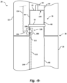
- Fig. 9 depicts an embodiment the coupling 104 is configured through the external wall 108 of the receiving section 60 and into an interior of the beam structure 40.
- the coupling 104 includes mating components on an interior wall 111 of the beam structure 40, wherein the power or fluid medium is conveyed through an internal conduit 112 in the beam structure 40 into the second blade segment 30.
- the beam structure 40 may be an extension of the spar structure 66 running span-wise through the second blade segment 30. Again, this configuration defines a bypass 126 around the blockage 128.
- Fig. 10 depicts an embodiment the internal joint structure 36 includes one or more chord-wise walls 116 separating the first 32 and second 30 blade segments at the chord-wise joint 34.
- the coupling 104 includes one or more disconnectable conduits 118 for the power or fluid medium from the supply 114 in the first blade segment 30, through the chord-wise walls 116, and to the supply line or conduit 144 in the second blade segment 30.
- the present invention also encompasses a wind turbine 10 ( Fig. 1 ) that utilizes one or more of the jointed wind turbine blades 28 embodied herein.
- the present invention encompasses a method for supplying heat for deicing in a jointed wind turbine rotor blade 28, wherein the blade 28 includes a first blade segment 32 adjacent a root end 19 of the wind turbine rotor blade, a second blade segment 30 adjacent a tip end 17 of the wind turbine rotor blade, and internal joint structure 36 joining the first 32 and second 30 blade segments across a chord-wise joint 34 that separates the first and second blade segments.
- the method includes configuring a first heating system 100 within the first blade segment 32, and configuring a second heating system 102 within the second blade segment 30.
- a disconnectable coupling 104 is configured between the first 32 and second 30 blade segments at the chord-wise joint 34.
- the method includes supplying power or a fluid medium from a source 120 in the first blade segment 32, through the coupling 104, and across the chord-wise joint 34 for use by the second heating system 102 in the second blade segment 30.
Landscapes
- Engineering & Computer Science (AREA)
- Life Sciences & Earth Sciences (AREA)
- Sustainable Development (AREA)
- Sustainable Energy (AREA)
- Chemical & Material Sciences (AREA)
- Combustion & Propulsion (AREA)
- Mechanical Engineering (AREA)
- General Engineering & Computer Science (AREA)
- Physics & Mathematics (AREA)
- Thermal Sciences (AREA)
- Wind Motors (AREA)
Applications Claiming Priority (2)
| Application Number | Priority Date | Filing Date | Title |
|---|---|---|---|
| US16/132,732 US11236733B2 (en) | 2018-09-17 | 2018-09-17 | Heating system and method for a jointed wind rotor turbine blade |
| PCT/US2019/050952 WO2020060850A1 (en) | 2018-09-17 | 2019-09-13 | Heating system and method for a jointed wind rotor turbine blade |
Publications (2)
| Publication Number | Publication Date |
|---|---|
| EP3853476A1 EP3853476A1 (en) | 2021-07-28 |
| EP3853476B1 true EP3853476B1 (en) | 2024-06-26 |
Family
ID=68069895
Family Applications (1)
| Application Number | Title | Priority Date | Filing Date |
|---|---|---|---|
| EP19778743.5A Active EP3853476B1 (en) | 2018-09-17 | 2019-09-13 | Heating system and method for a jointed wind rotor turbine blade |
Country Status (6)
| Country | Link |
|---|---|
| US (2) | US11236733B2 (da) |
| EP (1) | EP3853476B1 (da) |
| CN (1) | CN112969855B (da) |
| DK (1) | DK3853476T3 (da) |
| ES (1) | ES2989419T3 (da) |
| WO (1) | WO2020060850A1 (da) |
Cited By (1)
| Publication number | Priority date | Publication date | Assignee | Title |
|---|---|---|---|---|
| EP3870837A1 (en) * | 2018-10-25 | 2021-09-01 | LM Wind Power A/S | Lightning protection for a wind turbine blade |
Families Citing this family (11)
| Publication number | Priority date | Publication date | Assignee | Title |
|---|---|---|---|---|
| WO2018206158A1 (en) * | 2017-05-09 | 2018-11-15 | Siemens Wind Power A/S | Lightning protection system for a wind turbine blade |
| CN107905961B (zh) * | 2017-11-09 | 2019-12-20 | 新疆金风科技股份有限公司 | 叶片的加热除冰系统及其方法、叶片和风力发电机组 |
| JP7234371B2 (ja) * | 2018-12-11 | 2023-03-07 | ゼネラル・エレクトリック・カンパニイ | 遷移形状を有するセグメント化されたロータブレード用のビーム構造 |
| US20210024221A1 (en) * | 2019-07-25 | 2021-01-28 | Airbus Operations Sas | Leading edge member for an airfoil of an aircraft |
| CN111878326B (zh) * | 2020-08-06 | 2021-11-26 | 上海电气风电集团股份有限公司 | 风机的结冰故障检测方法、系统、电子设备和介质 |
| CN112727713B (zh) * | 2021-01-06 | 2022-05-24 | 株洲时代新材料科技股份有限公司 | 风力发电机组叶片除冰系统及风力发电机组 |
| DE102021123954A1 (de) | 2021-09-16 | 2023-03-16 | Wobben Properties Gmbh | Windenergieanlagen-Rotorblatt |
| CN113700617A (zh) * | 2021-09-17 | 2021-11-26 | 中国华能集团清洁能源技术研究院有限公司 | 一种水平轴风力发电机组叶尖防除冰装置及安装方法 |
| EP4181388A1 (en) | 2021-11-10 | 2023-05-17 | General Electric Renovables España S.L. | Wind turbine and method of operating a wind turbine |
| CN114526192B (zh) * | 2022-03-18 | 2022-09-09 | 华能赫章风力发电有限公司 | 一种基于微波的防凝冻风机叶片 |
| CN114687963B (zh) * | 2022-03-18 | 2022-09-09 | 华能赫章风力发电有限公司 | 一种风力发电控制系统 |
Family Cites Families (18)
| Publication number | Priority date | Publication date | Assignee | Title |
|---|---|---|---|---|
| DE19528862A1 (de) | 1995-08-05 | 1997-02-06 | Aloys Wobben | Verfahren zum Enteisen eines Rotorblattes einer Windenergieanlage sowie zur Durchführung des Verfahrens geeignetes Rotorblatt |
| DE19644355A1 (de) | 1996-10-25 | 1998-04-30 | Johannes Drayer | Luftstrom- (Heißgas-) Rotorblattheizung |
| DK173607B1 (da) * | 1999-06-21 | 2001-04-30 | Lm Glasfiber As | Vindmøllevinge med system til afisning af lynbeskyttelse |
| US9765756B2 (en) | 2008-05-07 | 2017-09-19 | Vestas Wind Systems A/S | Sectional blade |
| US7931445B2 (en) | 2009-11-05 | 2011-04-26 | General Electric Company | Apparatus and method for cleaning an active flow control (AFC) system of a wind turbine |
| DE102010030472A1 (de) * | 2010-06-24 | 2011-12-29 | Repower Systems Ag | Rotorblattenteisung |
| US7922454B1 (en) * | 2010-10-29 | 2011-04-12 | General Electric Company | Joint design for rotor blade segments of a wind turbine |
| CN102434405B (zh) | 2011-12-27 | 2013-08-07 | 东南大学 | 热辅助超声波联合除冰装置及其控制方法 |
| DE102013206493A1 (de) | 2013-04-11 | 2014-10-16 | Wobben Properties Gmbh | Rotorblatt einer Windenergieanlage |
| US20150056074A1 (en) * | 2013-08-22 | 2015-02-26 | General Electric Company | System and method for deicing wind turbine rotor blades |
| US9605651B2 (en) * | 2013-12-04 | 2017-03-28 | General Electric Company | Spar assembly for a wind turbine rotor blade |
| US20150369211A1 (en) | 2014-06-19 | 2015-12-24 | General Electric Company | Wind blade tip joint |
| CN105626370B (zh) | 2014-10-30 | 2018-02-16 | 株洲时代新材料科技股份有限公司 | 一种抗冰风电叶片结构 |
| US9897065B2 (en) * | 2015-06-29 | 2018-02-20 | General Electric Company | Modular wind turbine rotor blades and methods of assembling same |
| US20160377052A1 (en) * | 2015-06-29 | 2016-12-29 | General Electric Company | Blade root section for a modular rotor blade and method of manufacturing same |
| EP3423712B8 (en) * | 2016-03-01 | 2020-11-11 | Borealis Wind Inc. | Wind turbine blade de-icing systems and methods |
| US10626846B2 (en) * | 2016-11-17 | 2020-04-21 | General Electric Company | System for wind turbine blade actuation |
| US10830214B2 (en) * | 2017-03-22 | 2020-11-10 | General Electric Company | Method for securing a lightning receptor cable within a segmented rotor blade |
-
2018
- 2018-09-17 US US16/132,732 patent/US11236733B2/en active Active
-
2019
- 2019-09-13 CN CN201980075792.XA patent/CN112969855B/zh active Active
- 2019-09-13 DK DK19778743.5T patent/DK3853476T3/da active
- 2019-09-13 EP EP19778743.5A patent/EP3853476B1/en active Active
- 2019-09-13 WO PCT/US2019/050952 patent/WO2020060850A1/en not_active Ceased
- 2019-09-13 ES ES19778743T patent/ES2989419T3/es active Active
-
2022
- 2022-01-31 US US17/588,376 patent/US11708817B2/en active Active
Cited By (1)
| Publication number | Priority date | Publication date | Assignee | Title |
|---|---|---|---|---|
| EP3870837A1 (en) * | 2018-10-25 | 2021-09-01 | LM Wind Power A/S | Lightning protection for a wind turbine blade |
Also Published As
| Publication number | Publication date |
|---|---|
| DK3853476T3 (da) | 2024-09-16 |
| US20200088172A1 (en) | 2020-03-19 |
| US20220154700A1 (en) | 2022-05-19 |
| US11236733B2 (en) | 2022-02-01 |
| CN112969855B (zh) | 2024-08-30 |
| WO2020060850A1 (en) | 2020-03-26 |
| US11708817B2 (en) | 2023-07-25 |
| ES2989419T3 (es) | 2024-11-26 |
| EP3853476A1 (en) | 2021-07-28 |
| CN112969855A (zh) | 2021-06-15 |
Similar Documents
| Publication | Publication Date | Title |
|---|---|---|
| US11708817B2 (en) | Heating system and method for a jointed wind rotor turbine blade | |
| CN105298739B (zh) | 风力叶片末梢接头 | |
| US20150056074A1 (en) | System and method for deicing wind turbine rotor blades | |
| CN101876293B (zh) | 具有预制的前缘段的风力涡轮叶片 | |
| JP7427656B2 (ja) | ジョイント風力タービンロータブレード用のスパー構成 | |
| EP3631198B1 (en) | Segmented rotor blade of a wind turbine with a joint assembly having flanged bushings | |
| EP3870834B1 (en) | Spar cap configuration for a jointed wind turbine blade | |
| US9745955B2 (en) | Wind turbine blade | |
| EP2795118B1 (en) | A wind turbine blade | |
| CN211900886U (zh) | 一种风电机组叶片气热除冰装置 | |
| US11408400B2 (en) | De-icing system for a wind turbine blade | |
| DK178632B1 (da) | System og fremgangsmåde til afisning af vindmøllerotorvinger | |
| EP3069020B1 (en) | Heating installation arrangement | |
| US20230151794A1 (en) | Wind turbine rotor blade |
Legal Events
| Date | Code | Title | Description |
|---|---|---|---|
| STAA | Information on the status of an ep patent application or granted ep patent |
Free format text: STATUS: UNKNOWN |
|
| STAA | Information on the status of an ep patent application or granted ep patent |
Free format text: STATUS: THE INTERNATIONAL PUBLICATION HAS BEEN MADE |
|
| PUAI | Public reference made under article 153(3) epc to a published international application that has entered the european phase |
Free format text: ORIGINAL CODE: 0009012 |
|
| STAA | Information on the status of an ep patent application or granted ep patent |
Free format text: STATUS: REQUEST FOR EXAMINATION WAS MADE |
|
| 17P | Request for examination filed |
Effective date: 20210331 |
|
| AK | Designated contracting states |
Kind code of ref document: A1 Designated state(s): AL AT BE BG CH CY CZ DE DK EE ES FI FR GB GR HR HU IE IS IT LI LT LU LV MC MK MT NL NO PL PT RO RS SE SI SK SM TR |
|
| DAV | Request for validation of the european patent (deleted) | ||
| DAX | Request for extension of the european patent (deleted) | ||
| P01 | Opt-out of the competence of the unified patent court (upc) registered |
Effective date: 20230522 |
|
| RAP1 | Party data changed (applicant data changed or rights of an application transferred) |
Owner name: LM WIND POWER A/S |
|
| GRAP | Despatch of communication of intention to grant a patent |
Free format text: ORIGINAL CODE: EPIDOSNIGR1 |
|
| STAA | Information on the status of an ep patent application or granted ep patent |
Free format text: STATUS: GRANT OF PATENT IS INTENDED |
|
| INTG | Intention to grant announced |
Effective date: 20240226 |
|
| GRAS | Grant fee paid |
Free format text: ORIGINAL CODE: EPIDOSNIGR3 |
|
| GRAA | (expected) grant |
Free format text: ORIGINAL CODE: 0009210 |
|
| STAA | Information on the status of an ep patent application or granted ep patent |
Free format text: STATUS: THE PATENT HAS BEEN GRANTED |
|
| AK | Designated contracting states |
Kind code of ref document: B1 Designated state(s): AL AT BE BG CH CY CZ DE DK EE ES FI FR GB GR HR HU IE IS IT LI LT LU LV MC MK MT NL NO PL PT RO RS SE SI SK SM TR |
|
| REG | Reference to a national code |
Ref country code: GB Ref legal event code: FG4D |
|
| REG | Reference to a national code |
Ref country code: CH Ref legal event code: EP |
|
| REG | Reference to a national code |
Ref country code: DE Ref legal event code: R096 Ref document number: 602019054261 Country of ref document: DE |
|
| REG | Reference to a national code |
Ref country code: DK Ref legal event code: T3 Effective date: 20240913 |
|
| PG25 | Lapsed in a contracting state [announced via postgrant information from national office to epo] |
Ref country code: BG Free format text: LAPSE BECAUSE OF FAILURE TO SUBMIT A TRANSLATION OF THE DESCRIPTION OR TO PAY THE FEE WITHIN THE PRESCRIBED TIME-LIMIT Effective date: 20240626 |
|
| PG25 | Lapsed in a contracting state [announced via postgrant information from national office to epo] |
Ref country code: FI Free format text: LAPSE BECAUSE OF FAILURE TO SUBMIT A TRANSLATION OF THE DESCRIPTION OR TO PAY THE FEE WITHIN THE PRESCRIBED TIME-LIMIT Effective date: 20240626 Ref country code: HR Free format text: LAPSE BECAUSE OF FAILURE TO SUBMIT A TRANSLATION OF THE DESCRIPTION OR TO PAY THE FEE WITHIN THE PRESCRIBED TIME-LIMIT Effective date: 20240626 |
|
| REG | Reference to a national code |
Ref country code: LT Ref legal event code: MG9D |
|
| PG25 | Lapsed in a contracting state [announced via postgrant information from national office to epo] |
Ref country code: GR Free format text: LAPSE BECAUSE OF FAILURE TO SUBMIT A TRANSLATION OF THE DESCRIPTION OR TO PAY THE FEE WITHIN THE PRESCRIBED TIME-LIMIT Effective date: 20240927 |
|
| PG25 | Lapsed in a contracting state [announced via postgrant information from national office to epo] |
Ref country code: LV Free format text: LAPSE BECAUSE OF FAILURE TO SUBMIT A TRANSLATION OF THE DESCRIPTION OR TO PAY THE FEE WITHIN THE PRESCRIBED TIME-LIMIT Effective date: 20240626 |
|
| REG | Reference to a national code |
Ref country code: NL Ref legal event code: MP Effective date: 20240626 |
|
| PG25 | Lapsed in a contracting state [announced via postgrant information from national office to epo] |
Ref country code: NO Free format text: LAPSE BECAUSE OF FAILURE TO SUBMIT A TRANSLATION OF THE DESCRIPTION OR TO PAY THE FEE WITHIN THE PRESCRIBED TIME-LIMIT Effective date: 20240926 Ref country code: LV Free format text: LAPSE BECAUSE OF FAILURE TO SUBMIT A TRANSLATION OF THE DESCRIPTION OR TO PAY THE FEE WITHIN THE PRESCRIBED TIME-LIMIT Effective date: 20240626 Ref country code: HR Free format text: LAPSE BECAUSE OF FAILURE TO SUBMIT A TRANSLATION OF THE DESCRIPTION OR TO PAY THE FEE WITHIN THE PRESCRIBED TIME-LIMIT Effective date: 20240626 Ref country code: GR Free format text: LAPSE BECAUSE OF FAILURE TO SUBMIT A TRANSLATION OF THE DESCRIPTION OR TO PAY THE FEE WITHIN THE PRESCRIBED TIME-LIMIT Effective date: 20240927 Ref country code: FI Free format text: LAPSE BECAUSE OF FAILURE TO SUBMIT A TRANSLATION OF THE DESCRIPTION OR TO PAY THE FEE WITHIN THE PRESCRIBED TIME-LIMIT Effective date: 20240626 Ref country code: BG Free format text: LAPSE BECAUSE OF FAILURE TO SUBMIT A TRANSLATION OF THE DESCRIPTION OR TO PAY THE FEE WITHIN THE PRESCRIBED TIME-LIMIT Effective date: 20240626 Ref country code: RS Free format text: LAPSE BECAUSE OF FAILURE TO SUBMIT A TRANSLATION OF THE DESCRIPTION OR TO PAY THE FEE WITHIN THE PRESCRIBED TIME-LIMIT Effective date: 20240926 |
|
| PG25 | Lapsed in a contracting state [announced via postgrant information from national office to epo] |
Ref country code: NL Free format text: LAPSE BECAUSE OF FAILURE TO SUBMIT A TRANSLATION OF THE DESCRIPTION OR TO PAY THE FEE WITHIN THE PRESCRIBED TIME-LIMIT Effective date: 20240626 |
|
| REG | Reference to a national code |
Ref country code: AT Ref legal event code: MK05 Ref document number: 1697905 Country of ref document: AT Kind code of ref document: T Effective date: 20240626 |
|
| REG | Reference to a national code |
Ref country code: ES Ref legal event code: FG2A Ref document number: 2989419 Country of ref document: ES Kind code of ref document: T3 Effective date: 20241126 |
|
| RAP2 | Party data changed (patent owner data changed or rights of a patent transferred) |
Owner name: GENERAL ELECTRIC RENOVABLES ESPANA, S.L. |
|
| PG25 | Lapsed in a contracting state [announced via postgrant information from national office to epo] |
Ref country code: NL Free format text: LAPSE BECAUSE OF FAILURE TO SUBMIT A TRANSLATION OF THE DESCRIPTION OR TO PAY THE FEE WITHIN THE PRESCRIBED TIME-LIMIT Effective date: 20240626 |
|
| PG25 | Lapsed in a contracting state [announced via postgrant information from national office to epo] |
Ref country code: PT Free format text: LAPSE BECAUSE OF FAILURE TO SUBMIT A TRANSLATION OF THE DESCRIPTION OR TO PAY THE FEE WITHIN THE PRESCRIBED TIME-LIMIT Effective date: 20241028 |
|
| PG25 | Lapsed in a contracting state [announced via postgrant information from national office to epo] |
Ref country code: PT Free format text: LAPSE BECAUSE OF FAILURE TO SUBMIT A TRANSLATION OF THE DESCRIPTION OR TO PAY THE FEE WITHIN THE PRESCRIBED TIME-LIMIT Effective date: 20241028 |
|
| PG25 | Lapsed in a contracting state [announced via postgrant information from national office to epo] |
Ref country code: PL Free format text: LAPSE BECAUSE OF FAILURE TO SUBMIT A TRANSLATION OF THE DESCRIPTION OR TO PAY THE FEE WITHIN THE PRESCRIBED TIME-LIMIT Effective date: 20240626 |
|
| PG25 | Lapsed in a contracting state [announced via postgrant information from national office to epo] |
Ref country code: EE Free format text: LAPSE BECAUSE OF FAILURE TO SUBMIT A TRANSLATION OF THE DESCRIPTION OR TO PAY THE FEE WITHIN THE PRESCRIBED TIME-LIMIT Effective date: 20240626 |
|
| PG25 | Lapsed in a contracting state [announced via postgrant information from national office to epo] |
Ref country code: AT Free format text: LAPSE BECAUSE OF FAILURE TO SUBMIT A TRANSLATION OF THE DESCRIPTION OR TO PAY THE FEE WITHIN THE PRESCRIBED TIME-LIMIT Effective date: 20240626 Ref country code: IS Free format text: LAPSE BECAUSE OF FAILURE TO SUBMIT A TRANSLATION OF THE DESCRIPTION OR TO PAY THE FEE WITHIN THE PRESCRIBED TIME-LIMIT Effective date: 20241026 |
|
| PG25 | Lapsed in a contracting state [announced via postgrant information from national office to epo] |
Ref country code: CZ Free format text: LAPSE BECAUSE OF FAILURE TO SUBMIT A TRANSLATION OF THE DESCRIPTION OR TO PAY THE FEE WITHIN THE PRESCRIBED TIME-LIMIT Effective date: 20240626 |
|
| PG25 | Lapsed in a contracting state [announced via postgrant information from national office to epo] |
Ref country code: RO Free format text: LAPSE BECAUSE OF FAILURE TO SUBMIT A TRANSLATION OF THE DESCRIPTION OR TO PAY THE FEE WITHIN THE PRESCRIBED TIME-LIMIT Effective date: 20240626 Ref country code: SK Free format text: LAPSE BECAUSE OF FAILURE TO SUBMIT A TRANSLATION OF THE DESCRIPTION OR TO PAY THE FEE WITHIN THE PRESCRIBED TIME-LIMIT Effective date: 20240626 |
|
| PG25 | Lapsed in a contracting state [announced via postgrant information from national office to epo] |
Ref country code: SM Free format text: LAPSE BECAUSE OF FAILURE TO SUBMIT A TRANSLATION OF THE DESCRIPTION OR TO PAY THE FEE WITHIN THE PRESCRIBED TIME-LIMIT Effective date: 20240626 |
|
| PG25 | Lapsed in a contracting state [announced via postgrant information from national office to epo] |
Ref country code: SM Free format text: LAPSE BECAUSE OF FAILURE TO SUBMIT A TRANSLATION OF THE DESCRIPTION OR TO PAY THE FEE WITHIN THE PRESCRIBED TIME-LIMIT Effective date: 20240626 Ref country code: SK Free format text: LAPSE BECAUSE OF FAILURE TO SUBMIT A TRANSLATION OF THE DESCRIPTION OR TO PAY THE FEE WITHIN THE PRESCRIBED TIME-LIMIT Effective date: 20240626 Ref country code: RO Free format text: LAPSE BECAUSE OF FAILURE TO SUBMIT A TRANSLATION OF THE DESCRIPTION OR TO PAY THE FEE WITHIN THE PRESCRIBED TIME-LIMIT Effective date: 20240626 Ref country code: PL Free format text: LAPSE BECAUSE OF FAILURE TO SUBMIT A TRANSLATION OF THE DESCRIPTION OR TO PAY THE FEE WITHIN THE PRESCRIBED TIME-LIMIT Effective date: 20240626 Ref country code: IS Free format text: LAPSE BECAUSE OF FAILURE TO SUBMIT A TRANSLATION OF THE DESCRIPTION OR TO PAY THE FEE WITHIN THE PRESCRIBED TIME-LIMIT Effective date: 20241026 Ref country code: EE Free format text: LAPSE BECAUSE OF FAILURE TO SUBMIT A TRANSLATION OF THE DESCRIPTION OR TO PAY THE FEE WITHIN THE PRESCRIBED TIME-LIMIT Effective date: 20240626 Ref country code: CZ Free format text: LAPSE BECAUSE OF FAILURE TO SUBMIT A TRANSLATION OF THE DESCRIPTION OR TO PAY THE FEE WITHIN THE PRESCRIBED TIME-LIMIT Effective date: 20240626 Ref country code: AT Free format text: LAPSE BECAUSE OF FAILURE TO SUBMIT A TRANSLATION OF THE DESCRIPTION OR TO PAY THE FEE WITHIN THE PRESCRIBED TIME-LIMIT Effective date: 20240626 |
|
| PG25 | Lapsed in a contracting state [announced via postgrant information from national office to epo] |
Ref country code: IT Free format text: LAPSE BECAUSE OF FAILURE TO SUBMIT A TRANSLATION OF THE DESCRIPTION OR TO PAY THE FEE WITHIN THE PRESCRIBED TIME-LIMIT Effective date: 20240626 |
|
| REG | Reference to a national code |
Ref country code: DE Ref legal event code: R097 Ref document number: 602019054261 Country of ref document: DE |
|
| PG25 | Lapsed in a contracting state [announced via postgrant information from national office to epo] |
Ref country code: MC Free format text: LAPSE BECAUSE OF FAILURE TO SUBMIT A TRANSLATION OF THE DESCRIPTION OR TO PAY THE FEE WITHIN THE PRESCRIBED TIME-LIMIT Effective date: 20240626 |
|
| REG | Reference to a national code |
Ref country code: CH Ref legal event code: PL |
|
| PLBE | No opposition filed within time limit |
Free format text: ORIGINAL CODE: 0009261 |
|
| STAA | Information on the status of an ep patent application or granted ep patent |
Free format text: STATUS: NO OPPOSITION FILED WITHIN TIME LIMIT |
|
| PG25 | Lapsed in a contracting state [announced via postgrant information from national office to epo] |
Ref country code: LU Free format text: LAPSE BECAUSE OF NON-PAYMENT OF DUE FEES Effective date: 20240913 |
|
| 26N | No opposition filed |
Effective date: 20250327 |
|
| REG | Reference to a national code |
Ref country code: BE Ref legal event code: MM Effective date: 20240930 |
|
| PG25 | Lapsed in a contracting state [announced via postgrant information from national office to epo] |
Ref country code: BE Free format text: LAPSE BECAUSE OF NON-PAYMENT OF DUE FEES Effective date: 20240930 |
|
| PG25 | Lapsed in a contracting state [announced via postgrant information from national office to epo] |
Ref country code: CH Free format text: LAPSE BECAUSE OF NON-PAYMENT OF DUE FEES Effective date: 20240930 |
|
| PG25 | Lapsed in a contracting state [announced via postgrant information from national office to epo] |
Ref country code: IE Free format text: LAPSE BECAUSE OF NON-PAYMENT OF DUE FEES Effective date: 20240913 |
|
| PG25 | Lapsed in a contracting state [announced via postgrant information from national office to epo] |
Ref country code: SE Free format text: LAPSE BECAUSE OF FAILURE TO SUBMIT A TRANSLATION OF THE DESCRIPTION OR TO PAY THE FEE WITHIN THE PRESCRIBED TIME-LIMIT Effective date: 20240626 |
|
| PGFP | Annual fee paid to national office [announced via postgrant information from national office to epo] |
Ref country code: DK Payment date: 20250820 Year of fee payment: 7 Ref country code: DE Payment date: 20250820 Year of fee payment: 7 |
|
| PGFP | Annual fee paid to national office [announced via postgrant information from national office to epo] |
Ref country code: GB Payment date: 20250820 Year of fee payment: 7 |
|
| PGFP | Annual fee paid to national office [announced via postgrant information from national office to epo] |
Ref country code: FR Payment date: 20250821 Year of fee payment: 7 |
|
| PG25 | Lapsed in a contracting state [announced via postgrant information from national office to epo] |
Ref country code: CY Free format text: LAPSE BECAUSE OF FAILURE TO SUBMIT A TRANSLATION OF THE DESCRIPTION OR TO PAY THE FEE WITHIN THE PRESCRIBED TIME-LIMIT; INVALID AB INITIO Effective date: 20190913 |
|
| REG | Reference to a national code |
Ref country code: DE Ref legal event code: R081 Ref document number: 602019054261 Country of ref document: DE Owner name: GENERAL ELECTRIC RENOVABLES ESPANA S.L., ES Free format text: FORMER OWNER: LM WIND POWER A/S, KOLDING, DK |
|
| PGFP | Annual fee paid to national office [announced via postgrant information from national office to epo] |
Ref country code: ES Payment date: 20251001 Year of fee payment: 7 |
|
| PG25 | Lapsed in a contracting state [announced via postgrant information from national office to epo] |
Ref country code: HU Free format text: LAPSE BECAUSE OF FAILURE TO SUBMIT A TRANSLATION OF THE DESCRIPTION OR TO PAY THE FEE WITHIN THE PRESCRIBED TIME-LIMIT; INVALID AB INITIO Effective date: 20190913 |
|
| REG | Reference to a national code |
Ref country code: GB Ref legal event code: 732E Free format text: REGISTERED BETWEEN 20260226 AND 20260304 |