EP3853509B1 - Tour de pose, et méthode de pose de conduites sur le fond d'une étendue d'eau - Google Patents
Tour de pose, et méthode de pose de conduites sur le fond d'une étendue d'eau Download PDFInfo
- Publication number
- EP3853509B1 EP3853509B1 EP19790062.4A EP19790062A EP3853509B1 EP 3853509 B1 EP3853509 B1 EP 3853509B1 EP 19790062 A EP19790062 A EP 19790062A EP 3853509 B1 EP3853509 B1 EP 3853509B1
- Authority
- EP
- European Patent Office
- Prior art keywords
- clamp
- laying
- along
- longitudinal axis
- supporting structure
- Prior art date
- Legal status (The legal status is an assumption and is not a legal conclusion. Google has not performed a legal analysis and makes no representation as to the accuracy of the status listed.)
- Active
Links
Images



Classifications
-
- F—MECHANICAL ENGINEERING; LIGHTING; HEATING; WEAPONS; BLASTING
- F16—ENGINEERING ELEMENTS AND UNITS; GENERAL MEASURES FOR PRODUCING AND MAINTAINING EFFECTIVE FUNCTIONING OF MACHINES OR INSTALLATIONS; THERMAL INSULATION IN GENERAL
- F16L—PIPES; JOINTS OR FITTINGS FOR PIPES; SUPPORTS FOR PIPES, CABLES OR PROTECTIVE TUBING; MEANS FOR THERMAL INSULATION IN GENERAL
- F16L1/00—Laying or reclaiming pipes; Repairing or joining pipes on or under water
- F16L1/12—Laying or reclaiming pipes on or under water
- F16L1/20—Accessories therefor, e.g. floats or weights
- F16L1/202—Accessories therefor, e.g. floats or weights fixed on or to vessels
- F16L1/207—Pipe handling apparatus
-
- B—PERFORMING OPERATIONS; TRANSPORTING
- B63—SHIPS OR OTHER WATERBORNE VESSELS; RELATED EQUIPMENT
- B63B—SHIPS OR OTHER WATERBORNE VESSELS; EQUIPMENT FOR SHIPPING
- B63B35/00—Vessels or similar floating structures specially adapted for specific purposes and not otherwise provided for
- B63B35/03—Pipe-laying vessels
-
- F—MECHANICAL ENGINEERING; LIGHTING; HEATING; WEAPONS; BLASTING
- F16—ENGINEERING ELEMENTS AND UNITS; GENERAL MEASURES FOR PRODUCING AND MAINTAINING EFFECTIVE FUNCTIONING OF MACHINES OR INSTALLATIONS; THERMAL INSULATION IN GENERAL
- F16L—PIPES; JOINTS OR FITTINGS FOR PIPES; SUPPORTS FOR PIPES, CABLES OR PROTECTIVE TUBING; MEANS FOR THERMAL INSULATION IN GENERAL
- F16L1/00—Laying or reclaiming pipes; Repairing or joining pipes on or under water
- F16L1/12—Laying or reclaiming pipes on or under water
- F16L1/16—Laying or reclaiming pipes on or under water on the bottom
- F16L1/18—Laying or reclaiming pipes on or under water on the bottom the pipes being S- or J-shaped and under tension during laying
- F16L1/19—Laying or reclaiming pipes on or under water on the bottom the pipes being S- or J-shaped and under tension during laying the pipes being J-shaped
-
- F—MECHANICAL ENGINEERING; LIGHTING; HEATING; WEAPONS; BLASTING
- F16—ENGINEERING ELEMENTS AND UNITS; GENERAL MEASURES FOR PRODUCING AND MAINTAINING EFFECTIVE FUNCTIONING OF MACHINES OR INSTALLATIONS; THERMAL INSULATION IN GENERAL
- F16L—PIPES; JOINTS OR FITTINGS FOR PIPES; SUPPORTS FOR PIPES, CABLES OR PROTECTIVE TUBING; MEANS FOR THERMAL INSULATION IN GENERAL
- F16L1/00—Laying or reclaiming pipes; Repairing or joining pipes on or under water
- F16L1/12—Laying or reclaiming pipes on or under water
- F16L1/20—Accessories therefor, e.g. floats or weights
- F16L1/202—Accessories therefor, e.g. floats or weights fixed on or to vessels
- F16L1/205—Pipe-laying ships
-
- F—MECHANICAL ENGINEERING; LIGHTING; HEATING; WEAPONS; BLASTING
- F16—ENGINEERING ELEMENTS AND UNITS; GENERAL MEASURES FOR PRODUCING AND MAINTAINING EFFECTIVE FUNCTIONING OF MACHINES OR INSTALLATIONS; THERMAL INSULATION IN GENERAL
- F16L—PIPES; JOINTS OR FITTINGS FOR PIPES; SUPPORTS FOR PIPES, CABLES OR PROTECTIVE TUBING; MEANS FOR THERMAL INSULATION IN GENERAL
- F16L1/00—Laying or reclaiming pipes; Repairing or joining pipes on or under water
- F16L1/12—Laying or reclaiming pipes on or under water
- F16L1/20—Accessories therefor, e.g. floats or weights
- F16L1/225—Stingers
Definitions
- the present invention relates to a laying tower for laying pipelines on a bed of a body of water.
- Pipelines for transporting hydrocarbons are laid on the bed of a body of water by means of laying vessels, each of which is configured for assembling the pipeline on board the laying vessel and for laying the pipeline as it is gradually assembled.
- the laying vessel comprises assembling equipment and a launching ramp for the so-called “S” launch or a laying tower for carrying out the so-called “J” launch.
- the letters "S” and “J” identify the type of launch in relation to the shape, which the pipeline assumes between the laying vessel and the bed of the body of water.
- the so-called "S” launch is particularly adapted for laying pipelines with high productivity on medium shallow sea-beds, while the so-called “J” launch is adapted for laying the pipeline on deep sea-beds and along steep escarpments.
- a laying vessel equipped with a laying tower as those disclosed in documents WO 2012/101233 and WO 2005/090844 comprises at least one area for prefabricating joints having a unitary length, generally 12 meters, for forming multiple joints having a multiple length of the unitary length.
- the multiple joints supply the laying tower in succession and are joined to the pipeline during construction, which is partly arranged in the body of water.
- the laying tower comprises a supporting structure, which can be hinged to the laying vessel; a clamp arranged in a given position along the supporting structure and a second clamp arranged above the first clamp and movable along the frame for providing a laying travel for advancing the pipeline towards the body of water having a length substantially equal to the length of the multiple joint, and a successive return travel.
- the movement of the pipeline comprises that at least one among the first and the second clamp is in contact with the pipeline in the construction phase. The joining of the multiple joints aligned with the pipeline in the construction phase is performed in the laying tower in a single work station and the time for performing this junction influences the overall laying time of the pipeline.
- a laying tower for laying pipelines on the bed of a body of water, the laying tower comprising:
- the second clamp is capable of performing laying travels guided by the supporting structure along the first section and above the first clamp and laying travels along the second section only partially guided by the supporting structure. It follows that the laying travels along the second section are not limited by the extension of the supporting structure of the laying tower and the laying tower is capable of laying relatively long multiple joints without needing an elevated height of the laying tower. A taller laying tower should be required supported by a larger laying vessel.
- the selective arrangement of the first clamp in a first position along the longitudinal axis and in a second position remote from the longitudinal axis allows the transit of the second clamp along the gripping zone of the first clamp and the transit of special bulky pieces, such as, for example, valve assemblies associated with the multiple joint.
- the possibility of arranging the second clamp above the first clamp allows the configuration of the laying tower to be changed between a first configuration, wherein the second clamp makes a laying travel above the first clamp with the limits imposed by the supporting structure and a second configuration, wherein the second clamp makes laying travels below the first clamp.
- the laying tower comprises a cable actuating device configured for controlling the position of the second clamp, both along the supporting structure and along the pipeline.
- the cable actuating device comprises two winches mounted to the supporting structure and two cables connected to the second clamp.
- the cables are parallel and act substantially in synchronism so as to avoid misalignments of the second clamp.
- the laying tower comprises a first arm hinged to the supporting structure and configured for supporting the first clamp and tilting the first clamp between the first and the second position.
- the operation is carried out by means of hydraulic actuators.
- the first clamp comprises a U-shaped structure; a plurality of first jaws and a plurality of first actuators supported by the U-shaped structure and configured for actuating the jaws between an open position and a closed position.
- the laying tower comprises a trolley, which comprises a frame; and two cursors, which are arranged on opposite sides of the frame and configured for engaging the guides.
- the second clamp is hung to the trolley and hinged to the trolley.
- the group formed by the trolley and by the second clamp is capable of being advanced along curved paths without transmitting particular stress to the pipeline and vice versa.
- the pipeline can assume a slight curvature.
- the second clamp comprises an annular structure; a plurality of second jaws; and a plurality of second actuators supported by the annular structure and configured for actuating the respective second jaws between a closed position and an open position. If, on the one hand, the annular structure does not allow the second clamp to be disengaged laterally from the pipeline, on the other, the annular structure allows gripping forces, distributed about the pipeline, to be exerted.
- the second clamp comprises a plurality of rollers for guiding the second clamp along the pipeline in order to prevent rubbing between the second clamp and the pipeline when the second clamp slides with respect to the pipeline.
- the laying tower comprises a supply and control system of the second clamp comprising at least one supply cable connected to the trolley for supplying hydraulic power and/or electricity to the second clamp and exchanging signals between the second clamp and a control station.
- the supply cable can be wound and unwound to follow the position of the trolley and the second clamp.
- the laying tower comprises a transfer clamp, which is arranged above the first clamp, it is configured for selectively clamping, releasing and supporting a multiple joint, and it is mounted to the supporting structure by means of a movable arm configured for arranging the transfer clamp between a rest position remote from the longitudinal axis; an operative position along the longitudinal axis; and an operative position offset with respect to the longitudinal axis.
- the transfer clamp grips the multiple joint at the lower end thereof when it is not yet aligned with the longitudinal axis and arranges it, by means of the movable arm, at the longitudinal axis.
- the transfer clamp is arranged in a position where it does not hinder the laying operations.
- the arm is hinged to the supporting structure and is telescopic to guarantee a positioning on a plane perpendicular to the longitudinal axis.
- the laying tower comprises a plurality of manipulator arms, which are mounted to the supporting structure above the first clamp, they can be selectively coupled to a multiple joint for transferring the multiple joint between a position offset with respect to the longitudinal axis and a position coincident with the longitudinal axis.
- the manipulator arms do not have the function of supporting the weight of the multiple joint.
- the multiple joint is held in position along the longitudinal axis by a plurality of guiding devices, which are configured for axially coupling, in a sliding manner, to a multiple joint.
- the upper free end of the multiple joints is housed in an aligning device, movable along the longitudinal axis and configured for keeping the multiple joint aligned with the longitudinal axis.
- the laying tower comprises a load device, which comprises an arm; an actuating mechanism for arranging the arm between a lowered position and a raised position substantially parallel to the longitudinal axis; and a plurality of gripping devices distributed along the arm for selectively gripping a multiple joint in a plurality of points.
- the transfer clamp and the manipulator arms grip a multiple joint arranged opposite the supporting structure while it is supported by the arm in the raised position and by the gripping devices.
- the supporting structure comprises a main frame hinged to the laying vessel about an axis; and a lower frame, said guides extending along the main frame and the lower frame.
- the lower frame has a dual function: when the second clamp is operative along the first section of the path, the lower frame acts as a traditional stinger of a laying tower; when the second clamp is operative along the second section of the path, the lower frame guides the trolley for at least a portion of the second section of the path.
- the supporting structure comprises an upper frame hinged to the main frame, movable between an operative position, wherein it defines the prolongation of the main frame and a rest position, wherein it is arranged side by side to the main frame.
- the upper frame is an appendage of the main frame and it is configured for supporting only the aligning device.
- the overall size of the laying tower is substantially similar to the size of a laying tower sized for multiple joints having a shorter length than the multiple joints, which can in fact be manipulated by the laying tower, the subject of the present invention.
- a laying vessel for laying pipelines on the bed of a body of water comprising a deck and a laying tower, which is hinged in proximity of said deck about an axis, which extends above and below said axis and is made according to the present invention.
- a laying vessel configured for carrying out laying operations with quadruple joints can carry out laying operations with hexajoints, when the same laying vessel is equipped with the laying tower, the subject of the present invention. This fact determines the possibility of modifying laying towers of existing laying vessels, making them more efficient in terms of productivity and versatility.
- the laying vessel comprises an assembling station mounted in a movable manner along the deck for being selectively arranged in an operative position about said longitudinal axis and above the first clamp for joining a multiple joint to the pipeline and a remote position with respect to the operative position.
- the laying vessel comprises a platform, movable between a horizontal rest position and an operative position parallel to the longitudinal axis for arranging, in proximity of the supporting structure, a multiple joint coupled to a special part of the pipeline.
- a laying method for laying pipelines on the bed of a body of water, the method comprising the steps of:
- the second clamp is movable along a path, which extends both above and below the first clamp and below the supporting structure, no constraints are imposed by the supporting structure on the length of the first section of the path, therefore, with the present method, it is possible to lay multiple joints for which the supporting structure would be undersized if such multiple joints were laid with the second clamp arranged above the first clamp.
- the second section is longer than the first section, in particular, the length of the first section is substantially equal to the length of a first multiple joint and the length of the second section is substantially equal to the length of a second multiple joint having a length greater than the first multiple joint.
- the method comprises guiding the second clamp by means of both the supporting structure and the pipeline, only by means of the supporting structure, and only by means of the pipeline.
- the second clamp slides for at least a part of the second section only along the pipeline.
- the method comprises releasing the second clamp from the supporting structure and guiding the second clamp uniquely by means of the pipeline in said body of water along at least a part of the second section.
- the second clamp is released from the supporting structure and the second clamp is uniquely guided by the pipeline.
- the method comprises moving the second clamp along the path by means of a cable actuating device, which allows the second clamp to be moved at a distance.
- the cable actuating device comprises two winches operated in synchronism and two cables connected to the second clamp to avoid torsions of the second clamp when the second clamp is not guided by the supporting structure.
- the method comprises selectively arranging the first clamp between a first position along said path and in a second position remote from said path.
- the first clamp does not hinder the passage of bulky pieces and the passage of the second clamp.
- the second clamp can operate both in a configuration, wherein the first clamp performs laying travels above the first clamp and in a configuration, wherein it performs laying travels below the first clamp.
- the transit possibility of the second clamp at the first clamp enables the passage from one configuration to the other seamlessly and without interrupting the pipeline laying operations.
- the operative configuration change of the laying tower allows laying operations to be carried out with multiple joints having a different length depending on the need and convenience.
- the method comprises selectively arranging the second clamp above the first clamp for operating with multiple joints having a length substantially equal to the length of the first section and below the first clamp for operating with multiple joints having a length substantially equal to the length of the second section.
- the method comprises guiding the second clamp along the pipeline by means of a plurality of rollers mounted in a rotatable manner on the second clamp.
- the method comprises supplying the second clamp with a supply cable.
- the supply cable is similar to an umbilical.
- a laying vessel 1 for laying a pipeline 2 on the bed 3 of a body of water 4 is globally represented, with reference to Figure 1 .
- the term "pipeline” is understood to mean both a complete pipeline and a pipeline in the process of being manufactured.
- unitary joint J is understood to mean a piece of tube having a unitary length, generally 12 meters, which is joined in a prefabrication station (not shown) to one or more unitary joints J to form "multiple joints" (QJ quadruple joint; HJ sextuple joint or hexajoint; and QJS quadruple joints comprising special pieces).
- the laying vessel 1 comprises a deck 5; and a laying tower 6, which is hinged to the laying vessel 1 close to the deck 5 about an axis A1 and extends above and below the first axis A1 and partly in the body of water 4.
- the laying tower 6 extends along a longitudinal axis A transverse to the axis A1 and it is selectively movable between a lowered position substantially parallel to the deck 5 and a raised position substantially perpendicular to the deck 5.
- a laying vessel 1 and to a laying tower 6 sized to lay a pipeline 2 to which quadruple joints QJ ( Figure 2 ) are progressively joined in successive steps, but which is also capable of operating with hexajoints HJ ( Figure 2 ).
- the definition of "multiple joint” comprises both the quadruple joints QJ ( Figure 2 ), and hexajoints HJ ( Figure 2 ).
- the longitudinal axis A identifies the axis along which the pipeline 2 and/or the multiple joint extend, when the pipeline 2 and/or the multiple joint are in the laying tower 6.
- the position of the pipeline 2 or of the multiple joint inside the laying tower 6 can be identified by the longitudinal axis A.
- the laying vessel 1 comprises an assembling station 7 mounted in a movable manner on the deck 5 for selectively being arranged in an operative position about the longitudinal axis A and a remote position with respect to the operative position; a platform 8 movable between a horizontal rest position and an operative position parallel to the longitudinal axis A for the loading of quadruple joints comprising special pieces QJS ( Figure 2 ), i.e. elements of a considerable size; and a prefabrication station, not shown in the attached Figures, wherein the unitary joints J ( Figure 2 ) are assembled to form the multiple joints.
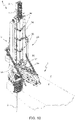
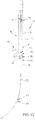
- the laying tower 6 comprises a supporting structure 9, which extends along the longitudinal axis A and comprises guides 10 parallel to the longitudinal axis A; a trolley 11 engageable in the guides 10 and selectively movable along a path P; a clamp 12, which is mounted on the supporting structure 9 and configured for selectively clamping and releasing the pipeline 2 ( Figure 1 ) in a given point along the longitudinal axis A; and a clamp 13, which is mounted on the trolley 11 and configured for selectively clamping and releasing the pipeline 2 ( Figure 1 ), both along a section T1 ( Figure 10 ) of path P extending above the clamp 12, and along a section of path T2 ( Figure 10 ), which extends below the clamp 12 and, partly, below the supporting structure 9.
- the supporting structure 9 comprises a main frame 14 hinged to the laying vessel 1 about the axis A1; and a lower frame 15.
- the main frame 14 comprises two longitudinal beams 16 substantially parallel to the longitudinal axis A; and transverse beams 17.
- the longitudinal beams 16 and the transverse beams 17 are made with box-like profiles, of a metal material.
- the lower frame 15 is mounted at the lower end of the main frame 14 and defined by a reticular structure, which is generally called a "stinger" in the sector of pipeline laying.
- the laying tower 6 comprises an upper frame 18, which, in this case, is a reticular structure, hinged to the main frame 14 and selectively movable between an operative position, wherein it defines the prolongation of the main frame 14, and a rest position, not shown in the attached Figures and wherein it is arranged side by side to the main frame 14.
- the clamp 12 is mounted to the supporting structure 9 so as to be selectively arranged in a first position along the longitudinal axis A ( Figure 5 ) and in a second position remote from the longitudinal axis A ( Figure 6 ).
- the laying tower 6 comprises an arm 19, which is hinged to the supporting structure 9, configured for supporting the clamp 12 and tilting the clamp 12 between the first ( Figure 5 ) and the second position ( Figure 6 ) by means of an actuation not shown in the attached Figures.
- the clamp 12 comprises a U-shaped plan structure 20; a plurality of jaws (not shown in the attached Figures) and a plurality of actuators 21 supported by the U-shaped structure 20 and configured to actuate the jaws (not shown) between an open position and a closed position.
- the trolley 11 comprises a frame 22; and two cursors 23 integral with the frame 22, which are arranged on opposite sides of the frame 22, configured to engage the guides 10 ( Figures 3 and 4 ).
- the frame 22 further has a central opening for housing the pipeline 2 or a multiple joint with clearance.
- the clamp 13 is hung to the trolley 11 and hinged to the trolley 11 so as to be able to oscillate freely with respect to the trolley 11 about an axis and comprises an annular structure 24; a plurality of jaws 25; and a plurality of actuators 26 supported by the annular structure 24 and configured to actuate the respective jaws 25 between a closed position and an open position.
- the clamp 13 further comprises rollers 27, configured for guiding the clamp 13 along the pipeline 2.
- the rollers 27 are mounted to the annular structure 24 and at the opposite ends of the clamp 13 with the function of favouring the sliding of the clamp 13 along the pipeline 2 or the multiple joint without damaging the pipeline 2 and the multiple joint.
- the laying tower 6 comprises a cable actuating device 28 configured to control the position of the trolley 11 and the clamp 13 along the supporting structure 9 and along the pipeline 1 below the supporting structure 9.
- the trolley 11 is guided by the supporting structure 9 along the main frame 14 and along the lower frame 15 by the guides 10 and can come out of the guides 10 in the body of water 4.
- the trolley 11 and the clamp 13 are integrally coupled to the pipeline 2 or they are guided by the pipeline 2 inside the body of water 4.
- each guide 10 substantially has a recess, the lower ends of which are open and, in particular, flared.
- the cable actuating device 28 comprises two winches 29 mounted to the supporting structure 9; two cables 30 connected to the trolley 11 and two return pulleys 31 mounted to the supporting structure 9 above the respective winches 29.
- the laying tower 6 comprises a supply and control system, which comprises two umbilical cables 32 parallel to the cables 30 and connected to the trolley 11 and to the clamp 13.
- the umbilical cables 32 contain hydraulic pipes, electric cables and signal cables (not shown in the attached Figures, for actuating and respectively controlling the clamp 13.
- the laying tower 6 comprises a supply and guiding system for supplying and guiding the multiple joints in a given position in the laying tower 6.
- a joint QJ is illustrated in Figure 9
- a joint HJ is illustrated in Figure 10 .
- the multiple joints from the deck 5 of the laying vessel 1 must be arranged between the two longitudinal beams 17 in alignment and in contact with the pipeline 2 in order to be able to join the multiple joint to the pipeline 2 held by the clamp 12 (not visible in Figure 9 ).
- the supply and guiding system comprises a load device 33, which comprises an arm 34 hinged about the axis A1; an actuating mechanism 35 for selectively arranging the arm 34 between a lowered position substantially parallel and close to the deck 5 of the laying vessel 1 ( Figure 9 ) and a raised position substantially parallel to the longitudinal axis A of the laying tower 6 ( Figure 6 ); and a plurality of gripping devices 36 distributed along the arm 34 for selectively gripping a multiple joint in a plurality of points and releasing the multiple joint.
- the arm 34 extends for almost the entire length of the laying tower 6 and has the function of arranging a multiple joint close to the longitudinal axis A.
- the supply and guiding system comprises devices associated with the laying tower 6 for transferring the multiple joint from the arm 34 to the laying tower 6 in alignment with the pipeline 2 and the longitudinal axis A.
- the laying tower 6 comprises a transfer clamp 37, which is arranged above the clamp 12, it is configured for selectively clamping, releasing and supporting a multiple joint in proximity of the lower end of the same, and it is mounted to the supporting structure 9 by means of a movable arm 38 configured for arranging the transfer clamp 37 between a rest position remote from the longitudinal axis A; an operative position along the longitudinal axis A; and a second operative position offset with respect to said longitudinal axis A.
- a transfer clamp 37 which is arranged above the clamp 12, it is configured for selectively clamping, releasing and supporting a multiple joint in proximity of the lower end of the same, and it is mounted to the supporting structure 9 by means of a movable arm 38 configured for arranging the transfer clamp 37 between a rest position remote from the longitudinal axis A; an operative position along the longitudinal axis A; and a second operative position offset with respect to said longitudinal axis A.
- the movable arm 38 is hinged to the supporting structure 9 and it is telescopic.
- the transfer clamp 37 is configured to support the weight of the entire multiple joint.
- the supply and guiding system comprises a plurality of manipulator arms 39, which are mounted to the supporting structure 9 above the transfer clamp 37, they can be selectively coupled to a multiple joint for transferring the multiple joint from a position offset with respect to the longitudinal axis A and a position coincident with the longitudinal axis A. Basically, between a multiple joint held by the load device 33 ( Figure 7 ), when the arm 34 is parallel to the longitudinal axis A.
- the supply and guiding system comprises a plurality of guiding elements 40, which are mounted in a retractable manner on the supporting structure 9 and configured for axially coupling in a sliding manner to a multiple joint.
- the supply and guiding system comprises an aligning device 41 movable along the longitudinal axis A, and configured for housing the upper free end of a multiple joint.
- the aligning device 41 is mounted in a sliding manner parallel to the longitudinal axis A on the upper frame 18 to support the upper end of the multiple joint having a length equal to six times the length of the unitary joint.
- the aligning device 41 is designed to operate only with the hexajoints HJ since the alignment of the quadruple joints QJ can be carried out by the clamp 13.
- a sequence of laying steps is described, wherein the laying tower 6 passes from a configuration for laying a pipeline 2 to which quadruple joints QJ are progressively joined ( Figure 2 ), to a configuration, wherein the pipeline 2 is joined, in successive steps, to hexajoints HJ ( Figure 2 ).
- the clamp 13 performs travels along the section T1 of the path P above the clamp 12 where such travels are substantially equal to the length of a quadruple joint QJ.
- the clamp 13 is shown with a continuous line at the upper end of the section T1 of the path P and sketched at the lower end of the section T1 of the path P, directly above the clamp 12.
- a quadruple joint QJ is supplied to the supporting structure and aligned with the pipeline 2
- the clamp 13 is lowered and inserted about the quadruple joint QJ at the upper end of the quadruple joint QJ.
- the clamp 13 grips the quadruple joint QJ in a given position depending on the laying travel it has to complete and on the position the clamp 13 must be in after completing the laying travel.
- the assembling station (not shown in Figure 8 ) joins the quadruple joint QJ to the free end of the pipeline 2 held in position by the clamp 12.
- the clamp 12 After completing the joining of the quadruple joint QJ to the pipeline 2, the clamp 12 is released and tilted in the configuration shown with sketched lines so as to allow the passage of the clamp 13, at the clamp 12.
- the travel downwards or laying travel of the clamp 13 is equal to the length of the quadruple joint QJ and the clamp 13 is stopped below the clamp 12, which is arranged in position again (with a complete line) ready to grip the pipeline 2.
- the new position of the clamp 13 along the section T2 of the path P was determined by the choice of the point in which the clamp 13 gripped the quadruple joint QJ in the section T1 of the path P.
- the laying tower 9 When the clamp 13 is arranged along the section T2 of path P, the laying tower 9 is ready to receive the hexajoints HJ.
- a hexajoint HJ is loaded into the supporting structure 9 in the same way as the quadruple joints QJ are loaded. The only difference lies in the fact that the hexajoint HJ is aligned by means of the aligning device 41 instead of with the clamp 13.
- the clamp 12 releases the pipeline 2, and the clamp 13 performs a laying travel equal to the length of the hexajoint HJ along the section T2.
- the laying travel of the clamp 13 along the section T2 is completed, partly, along the supporting structure 9 and, partly, freely in the body of water below the supporting structure 9.
- the clamp 13 is guided by the pipeline 2, which starts to bend slightly (the extent of the curvature depends on the depth of the seabed). Then, the clamp 13 is brought back by the cable actuating device 28 into the position directly below the clamp 12.
- the clamp 13 can be brought back to the section T1 of the path P.
- the clamp 13 grips the pipeline 2 in proximity of the clamp 12 and below the clamp 12, which is tilted to allow the passage of the clamp 13.
- the clamp 13 is arranged along the section T1
- the clamp 12 is positioned in the operative position and grips the pipeline 2 so that the pipeline 2 has the free end thereof at the assembling station 7.
- the clamp 13 releases the pipeline 2 and is then taken to the upper end of the section T1 of the path P, to allow the loading of a quadruple joint QJ or a quadruple joint comprising a special piece.
Landscapes
- Engineering & Computer Science (AREA)
- General Engineering & Computer Science (AREA)
- Mechanical Engineering (AREA)
- Chemical & Material Sciences (AREA)
- Combustion & Propulsion (AREA)
- Ocean & Marine Engineering (AREA)
- Supports For Pipes And Cables (AREA)
Claims (34)
- Tour de pose pour poser des conduites sur le fond d'une étendue d'eau, la tour de pose (6) comprenant :- une structure de support (9) s'étendant le long d'un axe longitudinal (A) et comprenant des guides (10) parallèles à l'axe longitudinal (A) ;- un premier dispositif de serrage en forme de U (12) qui est monté sur la structure de support (9) et configuré pour serrer et libérer sélectivement la conduite (2) à un point donné le long de l'axe longitudinal (A) et comprend une structure en forme de U (20) et une pluralité de premières mâchoires et une pluralité de premiers actionneurs (21) supportés par la structure en forme de U (20) et configurés pour actionner les mâchoires entre une position ouverte et une position fermée ;- un second dispositif de serrage (13) qui est mobile le long d'une trajectoire (P) qui s'étend le long d'une première section (T1) s'étendant au-dessus du premier dispositif de serrage (12) ; et une seconde section (T2) agencée au-dessous du premier dispositif de serrage (12) et partiellement au-dessous de la structure de support (9) et configurée pour serrer et libérer sélectivement la conduite (2) le long de la trajectoire (P), dans lequel le premier dispositif de serrage (12) est monté sur la structure de support (9) afin d'être agencé sélectivement dans une première position le long de l'axe longitudinal (A) et dans une seconde position à distance de l'axe longitudinal (A).
- Tour de pose selon la revendication 1, et comprenant un dispositif d'actionnement de câble (28) configuré pour contrôler la position du second dispositif de serrage (13) le long de la structure de support (9) et/ou le long de la conduite (2).
- Tour de pose selon la revendication 2, dans laquelle le dispositif d'actionnement de câble (28) comprend deux treuils (29) montés sur la structure de support (9) et deux câbles raccordés au second dispositif de serrage (13).
- Tour de pose selon l'une quelconque des revendications précédentes, et comprenant un premier bras (19) qui est articulé par rapport à la structure de support (9) et configuré pour supporter le premier dispositif de serrage (12) et incliner le premier dispositif de serrage (12) entre la première et la seconde position.
- Tour de pose selon l'une quelconque des revendications précédentes, et comprenant un chariot (11) comprenant un bâti (22) ; et deux curseurs (23) qui sont agencés sur les côtés opposés du bâti (22) et configurés pour mettre en prise lesdits guides (10).
- Tour de pose selon la revendication 5, dans laquelle le second dispositif de serrage (13) est configuré pour être suspendu au chariot (11) et articulé par rapport au chariot (11).
- Tour de pose selon l'une quelconque des revendications précédentes, dans laquelle le second dispositif de serrage (13) comprend une structure annulaire (24) ; une pluralité de secondes mâchoires (25) ; et une pluralité de seconds actionneurs (26) supportés par la structure annulaire (24) et configurés pour actionner les secondes mâchoires (25) respectives entre une position fermée et une position ouverte.
- Tour de pose selon l'une quelconque des revendications précédentes, dans laquelle le second dispositif de serrage (13) comprend une pluralité de rouleaux (27) pour guider le second dispositif de serrage (13) le long de la conduite (2).
- Tour de pose selon l'une quelconque des revendications précédentes, et comprenant un système d'alimentation et de contrôle du second dispositif de serrage (13) comprenant au moins un câble d'alimentation (32) raccordé au second dispositif de serrage (13).
- Tour de pose selon l'une quelconque des revendications précédentes, et comprenant un dispositif de serrage de transfert (37) qui est agencé au-dessus du premier dispositif de serrage (12), configuré pour serrer, libérer et supporter sélectivement un joint multiple, et monté sur la structure de support (9) au moyen d'un bras mobile (38), configuré pour agencer le dispositif de serrage de transfert (37) entre une position de repos à distance de l'axe longitudinal (A) ; une position opérationnelle le long de l'axe longitudinal (A); et une position opérationnelle décalée par rapport à l'axe longitudinal (A).
- Tour de pose selon la revendication 10, dans laquelle le bras (38) est articulé par rapport à la structure de support (9) et est télescopique.
- Tour de pose selon l'une quelconque des revendications précédentes, et comprenant une pluralité de bras manipulateurs (39) qui sont montés sur la structure de support (9) au-dessus du premier dispositif de serrage (12), ils sont sélectivement serrés sur un joint multiple pour transférer le joint multiple entre une position décalée par rapport à l'axe longitudinal (A) et une position coïncidant avec l'axe longitudinal (A) .
- Tour de pose selon l'une quelconque des revendications précédentes, et comprenant une pluralité de dispositifs de guidage (40) qui sont configurés pour se coupler axialement, d'une manière coulissante, au joint multiple.
- Tour de pose selon l'une quelconque des revendications précédentes, et comprenant un dispositif d'alignement (41) mobile le long de l'axe longitudinal (A) et configuré pour loger l'extrémité libre supérieure d'un joint multiple ; ledit dispositif d'alignement étant monté sur la structure de support (9) d'une manière mobile pour maintenir le joint multiple aligné avec l'axe longitudinal (A).
- Tour de pose selon l'une quelconque des revendications précédentes, et comprenant un dispositif de charge qui comprend un bras (34) ; un mécanisme d'actionnement (35) pour agencer le bras (34) entre une position abaissée et une position levée sensiblement parallèle à l'axe longitudinal (A) ; et une pluralité de dispositifs de préhension (36) répartis le long du bras (34) pour saisir sélectivement un joint multiple en une pluralité de points.
- Tour de pose selon l'une quelconque des revendications précédentes, dans laquelle la structure de support (9) comprend un bâti principal (14) articulé par rapport au navire de pose (1) autour d'un axe (A1) ; et un bâti inférieur (15), lesdits guides (10) s'étendant le long du bâti principal (14) et du bâti inférieur (15).
- Tour de pose selon l'une quelconque des revendications précédentes, dans laquelle la structure de support (9) comprend un bâti principal (14) articulé par rapport au navire de pose (1) autour d'un axe (A1) ; et un bâti supérieur (18) articulé par rapport au bâti principal (14) et mobile entre une position opérationnelle, dans laquelle on définit le prolongement du bâti principal (14), et une position de repos, dans laquelle il est agencé côte à côte avec le bâti principal (14) .
- Navire de pose pour poser des conduites sur le fond d'une étendue d'eau, le navire de pose (1) comprenant un pont (5) et une tour de pose (6), qui est articulée à proximité dudit pont (5) autour d'un axe (A1), s'étendant au-dessus et au-dessous de l'axe (A1) et est réalisée selon l'une quelconque des revendications précédentes.
- Navire de pose selon la revendication 18, et comprenant une station d'assemblage (7) montée d'une manière mobile le long du pont (5) pour être sélectivement agencée dans une position opérationnelle autour dudit axe longitudinal (A) et au-dessus du premier dispositif de serrage (12) pour assembler un joint multiple à la conduite (2) et une position à distance par rapport à la position opérationnelle.
- Navire de pose selon la revendication 18 ou 19, et comprenant une plateforme (8), mobile entre une position de repos horizontale et une position opérationnelle parallèle à l'axe longitudinal (A) pour agencer un joint multiple couplé à une pièce spéciale de la conduite (2), à proximité de la structure de support (9) .
- Procédé de pose pour poser des conduites sur le fond d'une étendue d'eau, le procédé comprenant les étapes consistant à :- maintenir l'extrémité libre d'une conduite (2) dans une position donnée avec un premier dispositif de serrage en forme de U (12) agencé dans une structure de support (9) d'une tour de pose (6) ;- assembler un joint multiple à l'extrémité libre de la conduite (2) dans la tour de pose (6) au-dessus du premier dispositif de serrage (12) ;- serrer (2) la conduite avec un second dispositif de serrage (13), mobile le long d'une trajectoire donnée (P), qui s'étend le long d'une première section (T1) agencée au-dessus du premier dispositif de serrage (12) et le long d'une seconde section (T2) au-dessous du premier dispositif de serrage (12) et partiellement, au-dessous de la structure de support (9) ; et- libérer le premier dispositif de serrage (12) de la conduite (2) ;- agencer le premier dispositif de serrage (12) entre une première position le long de ladite trajectoire (P) et une seconde position à distance de ladite trajectoire (P) ; et- poser la conduite (2) au moyen d'une course du second dispositif de serrage (13) le long d'une partie de la trajectoire (P) ;- agencer sélectivement le second dispositif de serrage (13) au-dessus du premier dispositif de serrage (12) pour qu'il fonctionne avec des premiers joints multiples (QJ) ayant une longueur sensiblement égale à la longueur de la première section (T1) et au-dessous du premier dispositif de serrage (12) pour qu'il fonctionne avec des seconds joints multiples (HJ) ayant une longueur sensiblement égale à la longueur de la seconde section (T2) .
- Procédé de pose selon la revendication 21, dans lequel la première section (T1) est plus courte que la seconde section (T2), en particulier, la longueur de la première section (T1) est sensiblement égale à la longueur d'un premier joint multiple (QJ) et la longueur de la seconde (T2) est sensiblement égale à la longueur d'un second joint multiple (HJ).
- Procédé selon la revendication 21 ou 22, et comprenant l'étape consistant à guider le second dispositif de serrage (13) le long de la structure de support (9) et le long de la conduite (2).
- Procédé selon l'une quelconque des revendications 21 à 23, et comprenant l'étape consistant à libérer le second dispositif de serrage (13) de la structure de support (9) ; et guider le second dispositif de serrage (13) uniquement au moyen de la conduite (2) dans ladite étendue d'eau (4) le long d'au moins une partie de la seconde section (T2).
- Procédé selon l'une quelconque des revendications 21 à 24, et comprenant l'étape consistant à déplacer le second dispositif de serrage (13) le long de la trajectoire (P) au moyen d'un dispositif d'actionnement de câble (28).
- Procédé selon la revendication 25, dans lequel le dispositif d'actionnement de câble (28) comprend deux treuils (29) et deux câbles (30) raccordés au second dispositif de serrage (13).
- Procédé selon l'une quelconque des revendications 21 à 26, et comprenant l'étape consistant à guider le second dispositif de serrage (13) le long de la conduite (2) au moyen d'une pluralité de rouleaux (27) montés d'une manière rotative sur le second dispositif de serrage (13).
- Procédé selon l'une quelconque des revendications 21 à 27, et comprenant l'étape consistant à fournir le second dispositif de serrage (13) au moyen d'un câble d'alimentation (32).
- Procédé selon l'une quelconque des revendications 21 à 28, et comprenant l'étape consistant à supporter un joint multiple au moyen d'un dispositif de serrage de transfert (37) qui est agencé au-dessus du premier dispositif de serrage (12), configuré pour serrer, libérer et supporter sélectivement un joint multiple, et qui est monté sur la structure de support (9) au moyen d'un bras mobile (38), configuré pour agencer le dispositif de serrage de transfert (37) entre une position de repos à distance de l'axe longitudinal (A) ; une position opérationnelle le long de l'axe longitudinal (A); et une position opérationnelle décalée par rapport à l'axe longitudinal (A).
- Procédé selon l'une quelconque des revendications 21 à 29, et comprenant l'étape consistant à transférer un joint multiple entre une position décalée par rapport à l'axe longitudinal (A) et une position coïncidant avec l'axe longitudinal (A) au moyen d'une pluralité de bras manipulateurs (39) qui sont montés sur la structure de support (9) au-dessus du premier dispositif de serrage (12), et qui peuvent être sélectivement couplés à un joint multiple.
- Procédé selon l'une quelconque des revendications 21 à 30 et comprenant l'étape pour guider les joints multiples le long de la première section (T1) de la trajectoire (P) au moyen d'une pluralité de dispositifs de guidage (40), configurés pour se coupler axialement, d'une manière coulissante, à un joint multiple, et qui sont supportées par la structure de support (9).
- Procédé selon l'une quelconque des revendications 21 à 31, et comprenant les étapes consistant à loger l'extrémité supérieure d'un joint multiple au moyen d'un dispositif d'alignement (41) ; et à aligner le joint multiple avec l'axe longitudinal (A) au moyen du dispositif d'alignement (41).
- Procédé selon la revendication 32, et comprenant l'étape consistant à modifier la position du dispositif d'alignement (41) le long de l'axe longitudinal (A) pour ajuster la position du dispositif d'alignement (41) par rapport à la longueur du joint multiple.
- Procédé selon l'une quelconque des revendications 21 à 33, et comprenant l'étape consistant à amener les joints multiples à la structure de support (9) au moyen d'un dispositif de charge (33), qui comprend un bras (34) ; un mécanisme d'actionnement (35) pour agencer le bras (34) entre une position abaissée et une position levée sensiblement parallèle à l'axe longitudinal (A) ; et une pluralité de dispositifs de préhension (36) répartis le long du bras (34) pour saisir sélectivement un joint multiple en une pluralité de points.
Applications Claiming Priority (2)
| Application Number | Priority Date | Filing Date | Title |
|---|---|---|---|
| IT201800008685 | 2018-09-18 | ||
| PCT/IB2019/057868 WO2020058877A1 (fr) | 2018-09-18 | 2019-09-18 | Tour de pose et procédé pour poser des pipelines sur un fond d'une masse d'eau |
Publications (2)
| Publication Number | Publication Date |
|---|---|
| EP3853509A1 EP3853509A1 (fr) | 2021-07-28 |
| EP3853509B1 true EP3853509B1 (fr) | 2022-09-14 |
Family
ID=64557019
Family Applications (1)
| Application Number | Title | Priority Date | Filing Date |
|---|---|---|---|
| EP19790062.4A Active EP3853509B1 (fr) | 2018-09-18 | 2019-09-18 | Tour de pose, et méthode de pose de conduites sur le fond d'une étendue d'eau |
Country Status (4)
| Country | Link |
|---|---|
| US (1) | US11852265B2 (fr) |
| EP (1) | EP3853509B1 (fr) |
| AU (1) | AU2019343344A1 (fr) |
| WO (1) | WO2020058877A1 (fr) |
Families Citing this family (2)
| Publication number | Priority date | Publication date | Assignee | Title |
|---|---|---|---|---|
| GB2576767B (en) * | 2018-08-31 | 2020-09-16 | Acergy France SAS | Abandonment and recovery of pipelines |
| NL2026487B1 (en) * | 2020-09-16 | 2022-05-16 | Royal Ihc Ltd | Method and system for joining and deploying pipe |
Family Cites Families (9)
| Publication number | Priority date | Publication date | Assignee | Title |
|---|---|---|---|---|
| FR2773603B1 (fr) * | 1998-01-09 | 2000-02-18 | Coflexip | Dispositif et procede d'installation de conduites a tres grandes profondeurs |
| US7255515B2 (en) * | 2004-03-22 | 2007-08-14 | Itrec B.V. | Marine pipelay system and method |
| CN102084166B (zh) * | 2008-04-29 | 2015-04-29 | 伊特雷科公司 | 海中管道安装系统和方法 |
| GB0811437D0 (en) * | 2008-06-20 | 2008-07-30 | Saipem Spa | Pipe-laying vessel and method of laying a pipeline |
| ITMI20091639A1 (it) * | 2009-09-25 | 2011-03-26 | Saipem Spa | Metodo e gruppo di sollevamento per abbandonare e/o recuperare una tubazione subacquea tramite un natante di posa e natante di posa equipaggiato con tale gruppo di sollevamento |
| GB201101579D0 (en) * | 2011-01-28 | 2011-03-16 | Saipem Spa | Pipe-laying vessel and method of laying a pipeline |
| ITMI20121036A1 (it) * | 2012-06-14 | 2013-12-15 | Saipem Spa | Sistema e metodo di guida per varare una tubazione da un natante di posa a un letto di un corpo di acqua |
| EP3123066B1 (fr) * | 2014-03-25 | 2019-05-01 | SAIPEM S.p.A. | Dispositif de pose et procédé pour poser une canalisation sur le lit d'un corps d'eau |
| GB201614127D0 (en) * | 2016-08-18 | 2016-10-05 | Saipem Spa | A pipe-laying vessel |
-
2019
- 2019-09-18 EP EP19790062.4A patent/EP3853509B1/fr active Active
- 2019-09-18 AU AU2019343344A patent/AU2019343344A1/en not_active Abandoned
- 2019-09-18 WO PCT/IB2019/057868 patent/WO2020058877A1/fr not_active Ceased
- 2019-09-18 US US17/276,418 patent/US11852265B2/en active Active
Also Published As
| Publication number | Publication date |
|---|---|
| AU2019343344A1 (en) | 2021-05-13 |
| US20220163138A1 (en) | 2022-05-26 |
| BR112021005194A2 (pt) | 2021-06-08 |
| WO2020058877A1 (fr) | 2020-03-26 |
| EP3853509A1 (fr) | 2021-07-28 |
| US11852265B2 (en) | 2023-12-26 |
Similar Documents
| Publication | Publication Date | Title |
|---|---|---|
| EP2539223B1 (fr) | Système de pose de pipeline à bobine | |
| US10125895B2 (en) | Marine pipeline installation vessel and method | |
| AU2008233376B2 (en) | Pipeline laying vessel and method of laying a pipeline | |
| CN102027278B (zh) | 海洋铺管船舶、系统及方法 | |
| EP3853509B1 (fr) | Tour de pose, et méthode de pose de conduites sur le fond d'une étendue d'eau | |
| EP3137801B1 (fr) | Procédé de pose en déroulé de canalisations en mer ainsi que navire et procédé de pose de canalisations | |
| CN101657664A (zh) | 适用于管道铺设船的系统 | |
| WO2011098828A1 (fr) | Appareil et procédé d'installation de canalisation | |
| CN103339428A (zh) | 用于管敷设船的夹具组件以及敷设管线的方法 | |
| US20110286801A1 (en) | J-lay system with dual loading capability | |
| US7563055B2 (en) | Marine pipe laying system, method and hoisting device | |
| WO2015075555A1 (fr) | Mécanisme de transfert | |
| NL2012616B1 (en) | A tubular installation system for J-laying tubulars, marine pipelay system and method for handling a tubular or accessory. | |
| US20110250019A1 (en) | Vessel and method for laying a pipeline | |
| EP3500783B1 (fr) | Navire de pose de tuyaux | |
| BR112021005194B1 (pt) | Torre de assentamento, embarcação e método para assentar tubulações no leito de um corpo de água | |
| EP3224517B1 (fr) | Système de pose de canalisations sous-marines et procédé pour abaisser et/ou monter un pipeline en mer et comprenant un ou plusieurs accessoires associés |
Legal Events
| Date | Code | Title | Description |
|---|---|---|---|
| STAA | Information on the status of an ep patent application or granted ep patent |
Free format text: STATUS: UNKNOWN |
|
| STAA | Information on the status of an ep patent application or granted ep patent |
Free format text: STATUS: THE INTERNATIONAL PUBLICATION HAS BEEN MADE |
|
| PUAI | Public reference made under article 153(3) epc to a published international application that has entered the european phase |
Free format text: ORIGINAL CODE: 0009012 |
|
| STAA | Information on the status of an ep patent application or granted ep patent |
Free format text: STATUS: REQUEST FOR EXAMINATION WAS MADE |
|
| 17P | Request for examination filed |
Effective date: 20210322 |
|
| AK | Designated contracting states |
Kind code of ref document: A1 Designated state(s): AL AT BE BG CH CY CZ DE DK EE ES FI FR GB GR HR HU IE IS IT LI LT LU LV MC MK MT NL NO PL PT RO RS SE SI SK SM TR |
|
| DAV | Request for validation of the european patent (deleted) | ||
| DAX | Request for extension of the european patent (deleted) | ||
| GRAP | Despatch of communication of intention to grant a patent |
Free format text: ORIGINAL CODE: EPIDOSNIGR1 |
|
| STAA | Information on the status of an ep patent application or granted ep patent |
Free format text: STATUS: GRANT OF PATENT IS INTENDED |
|
| RIC1 | Information provided on ipc code assigned before grant |
Ipc: F16L 1/225 20060101ALI20220310BHEP Ipc: F16L 1/20 20060101ALI20220310BHEP Ipc: F16L 1/19 20060101AFI20220310BHEP |
|
| INTG | Intention to grant announced |
Effective date: 20220329 |
|
| GRAS | Grant fee paid |
Free format text: ORIGINAL CODE: EPIDOSNIGR3 |
|
| GRAA | (expected) grant |
Free format text: ORIGINAL CODE: 0009210 |
|
| STAA | Information on the status of an ep patent application or granted ep patent |
Free format text: STATUS: THE PATENT HAS BEEN GRANTED |
|
| AK | Designated contracting states |
Kind code of ref document: B1 Designated state(s): AL AT BE BG CH CY CZ DE DK EE ES FI FR GB GR HR HU IE IS IT LI LT LU LV MC MK MT NL NO PL PT RO RS SE SI SK SM TR |
|
| REG | Reference to a national code |
Ref country code: GB Ref legal event code: FG4D |
|
| REG | Reference to a national code |
Ref country code: CH Ref legal event code: EP |
|
| REG | Reference to a national code |
Ref country code: DE Ref legal event code: R096 Ref document number: 602019019640 Country of ref document: DE |
|
| REG | Reference to a national code |
Ref country code: IE Ref legal event code: FG4D |
|
| REG | Reference to a national code |
Ref country code: AT Ref legal event code: REF Ref document number: 1518883 Country of ref document: AT Kind code of ref document: T Effective date: 20221015 |
|
| REG | Reference to a national code |
Ref country code: NL Ref legal event code: FP |
|
| RAP4 | Party data changed (patent owner data changed or rights of a patent transferred) |
Owner name: SAIPEM S.P.A. |
|
| REG | Reference to a national code |
Ref country code: LT Ref legal event code: MG9D |
|
| PG25 | Lapsed in a contracting state [announced via postgrant information from national office to epo] |
Ref country code: SE Free format text: LAPSE BECAUSE OF FAILURE TO SUBMIT A TRANSLATION OF THE DESCRIPTION OR TO PAY THE FEE WITHIN THE PRESCRIBED TIME-LIMIT Effective date: 20220914 Ref country code: RS Free format text: LAPSE BECAUSE OF FAILURE TO SUBMIT A TRANSLATION OF THE DESCRIPTION OR TO PAY THE FEE WITHIN THE PRESCRIBED TIME-LIMIT Effective date: 20220914 Ref country code: NO Free format text: LAPSE BECAUSE OF FAILURE TO SUBMIT A TRANSLATION OF THE DESCRIPTION OR TO PAY THE FEE WITHIN THE PRESCRIBED TIME-LIMIT Effective date: 20221214 Ref country code: LV Free format text: LAPSE BECAUSE OF FAILURE TO SUBMIT A TRANSLATION OF THE DESCRIPTION OR TO PAY THE FEE WITHIN THE PRESCRIBED TIME-LIMIT Effective date: 20220914 Ref country code: LT Free format text: LAPSE BECAUSE OF FAILURE TO SUBMIT A TRANSLATION OF THE DESCRIPTION OR TO PAY THE FEE WITHIN THE PRESCRIBED TIME-LIMIT Effective date: 20220914 Ref country code: FI Free format text: LAPSE BECAUSE OF FAILURE TO SUBMIT A TRANSLATION OF THE DESCRIPTION OR TO PAY THE FEE WITHIN THE PRESCRIBED TIME-LIMIT Effective date: 20220914 |
|
| REG | Reference to a national code |
Ref country code: AT Ref legal event code: MK05 Ref document number: 1518883 Country of ref document: AT Kind code of ref document: T Effective date: 20220914 |
|
| PG25 | Lapsed in a contracting state [announced via postgrant information from national office to epo] |
Ref country code: HR Free format text: LAPSE BECAUSE OF FAILURE TO SUBMIT A TRANSLATION OF THE DESCRIPTION OR TO PAY THE FEE WITHIN THE PRESCRIBED TIME-LIMIT Effective date: 20220914 Ref country code: GR Free format text: LAPSE BECAUSE OF FAILURE TO SUBMIT A TRANSLATION OF THE DESCRIPTION OR TO PAY THE FEE WITHIN THE PRESCRIBED TIME-LIMIT Effective date: 20221215 |
|
| REG | Reference to a national code |
Ref country code: DE Ref legal event code: R119 Ref document number: 602019019640 Country of ref document: DE |
|
| PG25 | Lapsed in a contracting state [announced via postgrant information from national office to epo] |
Ref country code: SM Free format text: LAPSE BECAUSE OF FAILURE TO SUBMIT A TRANSLATION OF THE DESCRIPTION OR TO PAY THE FEE WITHIN THE PRESCRIBED TIME-LIMIT Effective date: 20220914 Ref country code: RO Free format text: LAPSE BECAUSE OF FAILURE TO SUBMIT A TRANSLATION OF THE DESCRIPTION OR TO PAY THE FEE WITHIN THE PRESCRIBED TIME-LIMIT Effective date: 20220914 Ref country code: PT Free format text: LAPSE BECAUSE OF FAILURE TO SUBMIT A TRANSLATION OF THE DESCRIPTION OR TO PAY THE FEE WITHIN THE PRESCRIBED TIME-LIMIT Effective date: 20230116 Ref country code: ES Free format text: LAPSE BECAUSE OF FAILURE TO SUBMIT A TRANSLATION OF THE DESCRIPTION OR TO PAY THE FEE WITHIN THE PRESCRIBED TIME-LIMIT Effective date: 20220914 Ref country code: CZ Free format text: LAPSE BECAUSE OF FAILURE TO SUBMIT A TRANSLATION OF THE DESCRIPTION OR TO PAY THE FEE WITHIN THE PRESCRIBED TIME-LIMIT Effective date: 20220914 Ref country code: AT Free format text: LAPSE BECAUSE OF FAILURE TO SUBMIT A TRANSLATION OF THE DESCRIPTION OR TO PAY THE FEE WITHIN THE PRESCRIBED TIME-LIMIT Effective date: 20220914 |
|
| REG | Reference to a national code |
Ref country code: BE Ref legal event code: MM Effective date: 20220930 |
|
| PG25 | Lapsed in a contracting state [announced via postgrant information from national office to epo] |
Ref country code: SK Free format text: LAPSE BECAUSE OF FAILURE TO SUBMIT A TRANSLATION OF THE DESCRIPTION OR TO PAY THE FEE WITHIN THE PRESCRIBED TIME-LIMIT Effective date: 20220914 Ref country code: PL Free format text: LAPSE BECAUSE OF FAILURE TO SUBMIT A TRANSLATION OF THE DESCRIPTION OR TO PAY THE FEE WITHIN THE PRESCRIBED TIME-LIMIT Effective date: 20220914 Ref country code: IS Free format text: LAPSE BECAUSE OF FAILURE TO SUBMIT A TRANSLATION OF THE DESCRIPTION OR TO PAY THE FEE WITHIN THE PRESCRIBED TIME-LIMIT Effective date: 20230114 Ref country code: EE Free format text: LAPSE BECAUSE OF FAILURE TO SUBMIT A TRANSLATION OF THE DESCRIPTION OR TO PAY THE FEE WITHIN THE PRESCRIBED TIME-LIMIT Effective date: 20220914 |
|
| P01 | Opt-out of the competence of the unified patent court (upc) registered |
Effective date: 20230420 |
|
| PG25 | Lapsed in a contracting state [announced via postgrant information from national office to epo] |
Ref country code: MC Free format text: LAPSE BECAUSE OF FAILURE TO SUBMIT A TRANSLATION OF THE DESCRIPTION OR TO PAY THE FEE WITHIN THE PRESCRIBED TIME-LIMIT Effective date: 20220914 Ref country code: LU Free format text: LAPSE BECAUSE OF NON-PAYMENT OF DUE FEES Effective date: 20220918 Ref country code: AL Free format text: LAPSE BECAUSE OF FAILURE TO SUBMIT A TRANSLATION OF THE DESCRIPTION OR TO PAY THE FEE WITHIN THE PRESCRIBED TIME-LIMIT Effective date: 20220914 |
|
| PLBE | No opposition filed within time limit |
Free format text: ORIGINAL CODE: 0009261 |
|
| STAA | Information on the status of an ep patent application or granted ep patent |
Free format text: STATUS: NO OPPOSITION FILED WITHIN TIME LIMIT |
|
| PG25 | Lapsed in a contracting state [announced via postgrant information from national office to epo] |
Ref country code: IE Free format text: LAPSE BECAUSE OF NON-PAYMENT OF DUE FEES Effective date: 20220918 Ref country code: DK Free format text: LAPSE BECAUSE OF FAILURE TO SUBMIT A TRANSLATION OF THE DESCRIPTION OR TO PAY THE FEE WITHIN THE PRESCRIBED TIME-LIMIT Effective date: 20220914 Ref country code: DE Free format text: LAPSE BECAUSE OF NON-PAYMENT OF DUE FEES Effective date: 20230401 |
|
| 26N | No opposition filed |
Effective date: 20230615 |
|
| PG25 | Lapsed in a contracting state [announced via postgrant information from national office to epo] |
Ref country code: SI Free format text: LAPSE BECAUSE OF FAILURE TO SUBMIT A TRANSLATION OF THE DESCRIPTION OR TO PAY THE FEE WITHIN THE PRESCRIBED TIME-LIMIT Effective date: 20220914 |
|
| PG25 | Lapsed in a contracting state [announced via postgrant information from national office to epo] |
Ref country code: BE Free format text: LAPSE BECAUSE OF NON-PAYMENT OF DUE FEES Effective date: 20220930 |
|
| P02 | Opt-out of the competence of the unified patent court (upc) changed |
Effective date: 20231123 |
|
| PG25 | Lapsed in a contracting state [announced via postgrant information from national office to epo] |
Ref country code: CY Free format text: LAPSE BECAUSE OF FAILURE TO SUBMIT A TRANSLATION OF THE DESCRIPTION OR TO PAY THE FEE WITHIN THE PRESCRIBED TIME-LIMIT Effective date: 20220914 |
|
| PG25 | Lapsed in a contracting state [announced via postgrant information from national office to epo] |
Ref country code: MK Free format text: LAPSE BECAUSE OF FAILURE TO SUBMIT A TRANSLATION OF THE DESCRIPTION OR TO PAY THE FEE WITHIN THE PRESCRIBED TIME-LIMIT Effective date: 20220914 Ref country code: HU Free format text: LAPSE BECAUSE OF FAILURE TO SUBMIT A TRANSLATION OF THE DESCRIPTION OR TO PAY THE FEE WITHIN THE PRESCRIBED TIME-LIMIT; INVALID AB INITIO Effective date: 20190918 |
|
| PG25 | Lapsed in a contracting state [announced via postgrant information from national office to epo] |
Ref country code: BG Free format text: LAPSE BECAUSE OF FAILURE TO SUBMIT A TRANSLATION OF THE DESCRIPTION OR TO PAY THE FEE WITHIN THE PRESCRIBED TIME-LIMIT Effective date: 20220914 |
|
| PG25 | Lapsed in a contracting state [announced via postgrant information from national office to epo] |
Ref country code: MT Free format text: LAPSE BECAUSE OF FAILURE TO SUBMIT A TRANSLATION OF THE DESCRIPTION OR TO PAY THE FEE WITHIN THE PRESCRIBED TIME-LIMIT Effective date: 20220914 |
|
| REG | Reference to a national code |
Ref country code: CH Ref legal event code: U11 Free format text: ST27 STATUS EVENT CODE: U-0-0-U10-U11 (AS PROVIDED BY THE NATIONAL OFFICE) Effective date: 20251001 |
|
| PGFP | Annual fee paid to national office [announced via postgrant information from national office to epo] |
Ref country code: IT Payment date: 20250922 Year of fee payment: 7 Ref country code: NL Payment date: 20250925 Year of fee payment: 7 |
|
| PGFP | Annual fee paid to national office [announced via postgrant information from national office to epo] |
Ref country code: GB Payment date: 20250923 Year of fee payment: 7 |
|
| PGFP | Annual fee paid to national office [announced via postgrant information from national office to epo] |
Ref country code: FR Payment date: 20250925 Year of fee payment: 7 |
|
| PG25 | Lapsed in a contracting state [announced via postgrant information from national office to epo] |
Ref country code: TR Free format text: LAPSE BECAUSE OF FAILURE TO SUBMIT A TRANSLATION OF THE DESCRIPTION OR TO PAY THE FEE WITHIN THE PRESCRIBED TIME-LIMIT Effective date: 20220914 |
|
| PGFP | Annual fee paid to national office [announced via postgrant information from national office to epo] |
Ref country code: CH Payment date: 20251001 Year of fee payment: 7 |