EP3853575B1 - Signalverarbeitung - Google Patents
Signalverarbeitung Download PDFInfo
- Publication number
- EP3853575B1 EP3853575B1 EP19734467.4A EP19734467A EP3853575B1 EP 3853575 B1 EP3853575 B1 EP 3853575B1 EP 19734467 A EP19734467 A EP 19734467A EP 3853575 B1 EP3853575 B1 EP 3853575B1
- Authority
- EP
- European Patent Office
- Prior art keywords
- signal
- amplitude
- temperature
- environmental
- compensation
- Prior art date
- Legal status (The legal status is an assumption and is not a legal conclusion. Google has not performed a legal analysis and makes no representation as to the accuracy of the status listed.)
- Active
Links
Images







Classifications
-
- G—PHYSICS
- G01—MEASURING; TESTING
- G01M—TESTING STATIC OR DYNAMIC BALANCE OF MACHINES OR STRUCTURES; TESTING OF STRUCTURES OR APPARATUS, NOT OTHERWISE PROVIDED FOR
- G01M5/00—Investigating the elasticity of structures, e.g. deflection of bridges or air-craft wings
- G01M5/0066—Investigating the elasticity of structures, e.g. deflection of bridges or air-craft wings by exciting or detecting vibration or acceleration
-
- G—PHYSICS
- G01—MEASURING; TESTING
- G01N—INVESTIGATING OR ANALYSING MATERIALS BY DETERMINING THEIR CHEMICAL OR PHYSICAL PROPERTIES
- G01N29/00—Investigating or analysing materials by the use of ultrasonic, sonic or infrasonic waves; Visualisation of the interior of objects by transmitting ultrasonic or sonic waves through the object
- G01N29/04—Analysing solids
-
- G—PHYSICS
- G01—MEASURING; TESTING
- G01M—TESTING STATIC OR DYNAMIC BALANCE OF MACHINES OR STRUCTURES; TESTING OF STRUCTURES OR APPARATUS, NOT OTHERWISE PROVIDED FOR
- G01M5/00—Investigating the elasticity of structures, e.g. deflection of bridges or air-craft wings
- G01M5/0025—Investigating the elasticity of structures, e.g. deflection of bridges or air-craft wings of elongated objects, e.g. pipes, masts, towers or railways
-
- G—PHYSICS
- G01—MEASURING; TESTING
- G01N—INVESTIGATING OR ANALYSING MATERIALS BY DETERMINING THEIR CHEMICAL OR PHYSICAL PROPERTIES
- G01N29/00—Investigating or analysing materials by the use of ultrasonic, sonic or infrasonic waves; Visualisation of the interior of objects by transmitting ultrasonic or sonic waves through the object
- G01N29/22—Details, e.g. general constructional or apparatus details
- G01N29/32—Arrangements for suppressing undesired influences, e.g. temperature or pressure variations, compensating for signal noise
- G01N29/326—Arrangements for suppressing undesired influences, e.g. temperature or pressure variations, compensating for signal noise compensating for temperature variations
-
- G—PHYSICS
- G01—MEASURING; TESTING
- G01M—TESTING STATIC OR DYNAMIC BALANCE OF MACHINES OR STRUCTURES; TESTING OF STRUCTURES OR APPARATUS, NOT OTHERWISE PROVIDED FOR
- G01M5/00—Investigating the elasticity of structures, e.g. deflection of bridges or air-craft wings
- G01M5/0041—Investigating the elasticity of structures, e.g. deflection of bridges or air-craft wings by determining deflection or stress
- G01M5/005—Investigating the elasticity of structures, e.g. deflection of bridges or air-craft wings by determining deflection or stress by means of external apparatus, e.g. test benches or portable test systems
- G01M5/0058—Investigating the elasticity of structures, e.g. deflection of bridges or air-craft wings by determining deflection or stress by means of external apparatus, e.g. test benches or portable test systems of elongated objects, e.g. pipes, masts, towers or railways
-
- G—PHYSICS
- G01—MEASURING; TESTING
- G01N—INVESTIGATING OR ANALYSING MATERIALS BY DETERMINING THEIR CHEMICAL OR PHYSICAL PROPERTIES
- G01N29/00—Investigating or analysing materials by the use of ultrasonic, sonic or infrasonic waves; Visualisation of the interior of objects by transmitting ultrasonic or sonic waves through the object
- G01N29/04—Analysing solids
- G01N29/041—Analysing solids on the surface of the material, e.g. using Lamb, Rayleigh or shear waves
-
- G—PHYSICS
- G01—MEASURING; TESTING
- G01N—INVESTIGATING OR ANALYSING MATERIALS BY DETERMINING THEIR CHEMICAL OR PHYSICAL PROPERTIES
- G01N29/00—Investigating or analysing materials by the use of ultrasonic, sonic or infrasonic waves; Visualisation of the interior of objects by transmitting ultrasonic or sonic waves through the object
- G01N29/04—Analysing solids
- G01N29/043—Analysing solids in the interior, e.g. by shear waves
-
- G—PHYSICS
- G01—MEASURING; TESTING
- G01N—INVESTIGATING OR ANALYSING MATERIALS BY DETERMINING THEIR CHEMICAL OR PHYSICAL PROPERTIES
- G01N29/00—Investigating or analysing materials by the use of ultrasonic, sonic or infrasonic waves; Visualisation of the interior of objects by transmitting ultrasonic or sonic waves through the object
- G01N29/04—Analysing solids
- G01N29/11—Analysing solids by measuring attenuation of acoustic waves
-
- G—PHYSICS
- G01—MEASURING; TESTING
- G01N—INVESTIGATING OR ANALYSING MATERIALS BY DETERMINING THEIR CHEMICAL OR PHYSICAL PROPERTIES
- G01N29/00—Investigating or analysing materials by the use of ultrasonic, sonic or infrasonic waves; Visualisation of the interior of objects by transmitting ultrasonic or sonic waves through the object
- G01N29/22—Details, e.g. general constructional or apparatus details
- G01N29/223—Supports, positioning or alignment in fixed situation
-
- G—PHYSICS
- G01—MEASURING; TESTING
- G01N—INVESTIGATING OR ANALYSING MATERIALS BY DETERMINING THEIR CHEMICAL OR PHYSICAL PROPERTIES
- G01N29/00—Investigating or analysing materials by the use of ultrasonic, sonic or infrasonic waves; Visualisation of the interior of objects by transmitting ultrasonic or sonic waves through the object
- G01N29/44—Processing the detected response signal, e.g. electronic circuits specially adapted therefor
-
- G—PHYSICS
- G01—MEASURING; TESTING
- G01N—INVESTIGATING OR ANALYSING MATERIALS BY DETERMINING THEIR CHEMICAL OR PHYSICAL PROPERTIES
- G01N29/00—Investigating or analysing materials by the use of ultrasonic, sonic or infrasonic waves; Visualisation of the interior of objects by transmitting ultrasonic or sonic waves through the object
- G01N29/44—Processing the detected response signal, e.g. electronic circuits specially adapted therefor
- G01N29/4463—Signal correction, e.g. distance amplitude correction [DAC], distance gain size [DGS], noise filtering
-
- G—PHYSICS
- G01—MEASURING; TESTING
- G01N—INVESTIGATING OR ANALYSING MATERIALS BY DETERMINING THEIR CHEMICAL OR PHYSICAL PROPERTIES
- G01N2291/00—Indexing codes associated with group G01N29/00
- G01N2291/01—Indexing codes associated with the measuring variable
- G01N2291/015—Attenuation, scattering
-
- G—PHYSICS
- G01—MEASURING; TESTING
- G01N—INVESTIGATING OR ANALYSING MATERIALS BY DETERMINING THEIR CHEMICAL OR PHYSICAL PROPERTIES
- G01N2291/00—Indexing codes associated with group G01N29/00
- G01N2291/02—Indexing codes associated with the analysed material
- G01N2291/023—Solids
-
- G—PHYSICS
- G01—MEASURING; TESTING
- G01N—INVESTIGATING OR ANALYSING MATERIALS BY DETERMINING THEIR CHEMICAL OR PHYSICAL PROPERTIES
- G01N2291/00—Indexing codes associated with group G01N29/00
- G01N2291/02—Indexing codes associated with the analysed material
- G01N2291/025—Change of phase or condition
- G01N2291/0258—Structural degradation, e.g. fatigue of composites, ageing of oils
-
- G—PHYSICS
- G01—MEASURING; TESTING
- G01N—INVESTIGATING OR ANALYSING MATERIALS BY DETERMINING THEIR CHEMICAL OR PHYSICAL PROPERTIES
- G01N2291/00—Indexing codes associated with group G01N29/00
- G01N2291/02—Indexing codes associated with the analysed material
- G01N2291/028—Material parameters
- G01N2291/0289—Internal structure, e.g. defects, grain size, texture
-
- G—PHYSICS
- G01—MEASURING; TESTING
- G01N—INVESTIGATING OR ANALYSING MATERIALS BY DETERMINING THEIR CHEMICAL OR PHYSICAL PROPERTIES
- G01N2291/00—Indexing codes associated with group G01N29/00
- G01N2291/26—Scanned objects
- G01N2291/262—Linear objects
- G01N2291/2623—Rails; Railroads
-
- G—PHYSICS
- G01—MEASURING; TESTING
- G01N—INVESTIGATING OR ANALYSING MATERIALS BY DETERMINING THEIR CHEMICAL OR PHYSICAL PROPERTIES
- G01N2291/00—Indexing codes associated with group G01N29/00
- G01N2291/26—Scanned objects
- G01N2291/263—Surfaces
- G01N2291/2634—Surfaces cylindrical from outside
Definitions
- the present invention relates to processing a signal obtained from a measurement, such as a guided or bulk elastic wave measurement, of a structure, such as a pipe, rail or plate.
- Permanently-installed systems enable frequent monitoring (e.g., daily), thus potentially allowing for the detection of damage at earlier stages. Furthermore, after detection, the progression of damage can be monitored, so that predictions on the remaining life of the structure can be attempted.
- Equation (1) is a simple model since interference of multiple modes (possibly dispersive) tends to produce a non-exact scaling. It has been shown experimentally, however, that making use of the model yields, in practical terms, satisfactory results. To address this problem, two techniques have been proposed, namely the optimal signal stretch and the local peak coherence techniques.
- US 2015/053009 describes a system for defect detection in plate like structures.
- the system comprises a plurality of transducers configured to be coupled to a periphery of complex-plate structure.
- a controller is electrically coupled to the plurality of transducers.
- the controller includes a machine readable storage medium and a processor in signal communication with the machine readable storage medium.
- the processor is configured to generate a plurality of guided wave signals using a first set of the plurality of transducers, receive the plurality of guided wave signals at a second set of the plurality of transducers, and generate tomographic pseudo-image of structural changes of the complex-plate structure based on the plurality of guided wave signals received at the second set of the plurality of transducers.
- US 2008/255771 A1 discloses a method of improving damage detection in a structural health monitoring system which includes obtaining a baseline set of signals corresponding to a range of values of an environmental effect variable for a plurality of first selected paths between pairs of a plurality of transducers configured in an array attached to a structure. Threshold levels are established for each of the selected paths for determining detection of damage in the structure based on differences in the baseline set of signals for the selected path. A current signal is acquired for each of the selected paths. The plurality of current signals are analyzed based on the threshold levels to detect damage in the structure.
- US 2018/231501 A1 describes methods for detecting and monitoring changes in mechanical structures and in walls of pipes, vessels and storage tanks, using muitimode acoustic signal propagation and detection.
- Acoustic signals having chosen amplitude-time-frequency characteristics excite multiple modes in the structure under investigation, are generated and received at a small number of accessible locations, such as the ends of pipes and the tops and bottoms of vessels and storage tanks, with the inspection region between transmit and receive transducers.
- Small mechanical changes lead to acoustic scattering and attenuation among the various modes, which are detectable as changes in received signal intensity. Such changes may include material loss, material conversion and material addition.
- the present method may be used to monitor the structure at a later time to determine whether changes have taken place. Methods for effective temperature compensation are also described.
- various pipe geometries and complex pipe geometries involving elbows, flanges, and the like can be monitored.
- an inspection system according to claim 18.
- the inspection system 1 includes a transducer assembly 3 (or "sensor") which is preferably permanently installed on the pipe 2, guided wave instrumentation 4, and a signal processing system 5.
- the structure may take the form of an extended structure such a plate, panel or rail.
- the transducer assembly 3 may take the form of an inspection ring, although other forms of transducer assembly 3 may be used.
- the transducer assembly 3 comprises a band 10 (or "collar") or other suitable structure which supports first and second arrays 11 1 , 11 2 of transducers 12 for generating ultrasonic waves 13 in the pipe 2 and detecting waves 14 reflected from defects 15.
- the transducers 12 preferably take the form of piezoelectric transducers and an example of suitable transducers can be found in GB 2 479 744 A .
- Each array 11 1 , 11 2 may comprise, for example, 16 or 32 transducers 12, although there may be fewer than 16, between 16 and 32 or more than 32 transducers 12.
- the transducers 12 can be grouped into sectors or channels (not shown), for example, eight channels (not shown), each channel (not shown) consisting of between 2 to 9 or more transducers 12.
- each array 11 1 , 11 2 are arranged such that, when the inspection ring 3 is installed, the transducers 12 are disposed around the periphery of the pipe 2.
- the first and second arrays 11 1 , 11 2 are offset across the width of the band 10 such that, when the inspection ring 3 is installed, the two arrays 11 1 , 11 2 are offset along a longitudinal axis 17 of the pipe 2.
- suitable inspection rings include the Compact TM ring, the High Definition (HD) solid ring, gPIMS (RTM) ring and other rings available from Guided Ultrasonics Ltd. (London, UK).
- Two separate rings 3, each having only a single array of transducers, can be used. Even for a pipe, an inspection ring 3 need not be used.
- a suitable planar array of transducers can be used, i.e. , a ring is not used.
- the guided wave instrumentation 4 includes a signal generator (not shown) capable of generating rf signals 18 having a suitable frequency, which is usually of the order tens of kilohertz (kHz), and a suitable shape, such as, for example, a k-cycle suitably-windowed tone burst, where k is a positive number equal to or greater than 1, preferably an integer or half integer, preferably taking a value in the range 3 ⁇ k ⁇ 10, and where a suitable windowing function can be a Gaussian function.
- the signal generator (not shown) feeds the rf signal 18 to a transmitter transducer 12 which converts the signal 18 into a guided wave in the pipe wall 2.
- the receiver transducer 12 converts a received guided wave into an electrical signal 19.
- the receiver transducer 12 feeds the electrical signal 19 to a signal receiver (not shown).
- the signal receiver may include an amplifier (not shown) and an analogue-to-digital converter (not shown) which generates a digitized signal of the electrical signal 19.
- the guided wave instrumentation 4 and signal processing system 5 may be integrated into a single unit.
- the signal processing system 5 may take the form of a lap-top, tablet or other form of portable computer.
- the signal processing system 5 may be remotely located, e.g., in a server farm, connected to the rest of the system via a communications network 6 which may include, for example, the Internet.
- a communications network 6 which may include, for example, the Internet.
- suitable guided wave instrumentation include G4 Mini (Full), Wavemaker G4, gPIMS Mini Collector and other instruments available from Guided Ultrasonics Ltd. (London, UK).
- the signal processing system 5 is implemented by a computer system 20 which comprises at least one processor 21, memory 22 and an input/output module 23 interconnected by a bus system 24.
- the system 20 may include a graphics processing unit 25 and a display 26.
- the system 20 may include user input device(s) 27 such as keyboard (not shown) and pointing device (not shown), a network interface 28 and storage 29 for example in the form of hard-disk drive(s) and/or solid-state drive.
- the storage 29 stores guided wave testing software 30, measurement data 31 and baseline data 32 and compensation curves 33.
- the computer system 20 may be used for controlling guided wave instrumentation 4 and so the storage 20 may include guided wave testing software (not shown).
- the system 1 may be used to inspect the pipe 2 to detect and/or to monitor development of cracks, corrosion and other defects (not shown) in the pipe 2 using guided waves 13, 14 in pulse-echo mode.
- a method of compensating for temperature-dependent variations in coherent noise can be applied to measured signals, preferably in the form of measured signals after compensating for temperature-dependent wave speed, for example using the process described in J. B. Harley and J. M. F. Moura: "Scale transform signal processing for optimal ultrasonic temperature compensation " ibid., or on signatures resulting from signal processing techniques such as independent component analysis (ICA).
- ICA independent component analysis
- the method is generally divided into two phases (or “stages”), namely a calibration phase (steps S1 to S3) and a monitoring operation phase (steps S4 to S7).
- the guided wave instrumentation 4 obtains a n sets of waveform data indicative of propagation of a generated signal through a structure 2 (such as a pipe), in an initial state, at different times and at different temperatures within a temperature range T LOW - T HIGH (step S1). This is used to form a so-called "baseline".
- the structure is deemed to be defect free. If a defect is already present before or during acquisition of these waveforms, the method would not give an indication of the pre-existing defect, but would still be able to detect further damage increases taking place after the baseline.
- the guided wave instrumentation 4 may apply a time-stretch temperature compensation of the baseline signals with respect to a chosen signal S 1 (step S2).
- a time-stretch temperature compensation of the baseline signals with respect to a chosen signal S 1 may be applied by applying the method described in J. B. Harley and J. M. F. Moura: "Scale transform signal processing for optimal ultrasonic temperature compensation " ibid ., which can be used to better align signal samples over different waveforms, wherein each signal sample corresponds to a specific location in the structure 2.
- the signal processing system 5 computes a set of signal amplitude - temperature curves 33 for each position d along the structure 2 (step S3). This is achieved by fitting the baseline data with an appropriate fitting curve, such as a polynomial of some order.
- the guided wave instrumentation 4 may compute the set of signal amplitude - temperature curves 33 for each position d along the structure 2.
- the guided wave instrumentation 4 acquires a waveform S i when the structure 2 is in an unknown state at some temperature T i (step S4).
- the temperature T i may lie in the range T LOW ⁇ T i ⁇ T HIGH . If the temperature T i lies outside of the baseline temperature range, then accuracy will depend on accuracy of extrapolation of the fitting curves. In the unknown state, damage may have occurred at one or more locations.
- the guided wave instrumentation 4 may, if applied to the baseline signals, apply the same time-stretch compensation algorithm applied to the baseline signals with respect to the previously chosen signal S 1 to S i (step S5).
- the guided wave instrumentation 4 subtracts, at each signal sample of S i , the value predicted by the curve computed for that sample and which is valid for a temperature equal to T i (step S6).
- the guided wave instrumentation 4 assesses whether there has been significant change in the structure 2 by looking at the residuals at each signal sample (step S7). For example, a change greater than variations in residual or component amplitude (i.e. , noise) seen with time in the calibration phase can be used as a threshold.
- the guided wave instrumentation 4 continues to acquire new signals for a continuous monitoring of the structural integrity (steps S4 to S7).
- a signal decomposition processing algorithm such as independent component analysis, and/or other signal processing, such as temperature compensation, can be applied to the acquired waveforms before the noise-reducing processing is performed.
- the pipe monitoring system 1 is installed, in this example, on an 8-inch, schedule 40 pipe 2 and set to use the T(0,1) mode with frequencies centred at 25.5 kHz.
- the transmitted signal 13 is an 8-cycle tone burst.
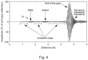
- the pipe was 4.5m long and featured a weld (not shown) at 1.5 m.
- a defect was artificially introduced at 2.5 m after the 379 th measurement and was gradually deepened.
- the cross-section area loss in % due to the presence of the defect is plotted (in chain) in Figure 8 .
- the signals are normalized to an end pipe reflection and stretched to compensate for the temperature-dependent wave speed using the process described in J. B. Harley and J. M. F. Moura: "Scale transform signal processing for optimal ultrasonic temperature compensation " ibid.
- the sample numbers are converted to distance from the sensor 3 by using the T(0,1) wave speed.
- Figure 5 shows measured temperature at the location of the sensor against measurement number. The temperature fluctuates between about 14 °C and 40 °C.
- FIG. 6 magnified plots of two signals, i.e. variation in normalised signal amplitude against distance d from the sensor 3, recorded at temperatures of 36°C and 20 °C are shown.
- Figure 6 shows the differences in coherent noise in the two cases. It could be inferred that before the weld at 1.5 m the noise is mainly due to circumferential modes. After the weld, the contribution of slower flexural and longitudinal modes to the coherent noise is also present. The methods herein described are able to compensate for this noise and for other phenomena hereinafter disclosed without the need for any prior knowledge of its source.
- the baseline there is an assumption that, for the first N measurements (i.e., the baseline), no damage growth occurs in the pipe 2. If, instead, some damage does grow while acquiring the baseline, the trend associated with its occurrence may be removed, but further damage increases taking place after the baseline would still be detected. There is no requirement that the pipe in its initial state is undamaged, simply that no significant new growth occurs. It is preferred that the baseline measurements be taken across the temperature range expected during normal operation of the pipe 2 being monitored. If the temperature exceeds this range, then out-of-range measurements can be excluded from analysis.
- a compensation curve 33 0 , 33 1 , 33 2 , ..., 33 D of amplitude against temperature is computed by fitting available baseline data.
- the goal of each curve 33 is to quantify the expected amplitude of the signal for a pipe in its original condition at that specific location and at each temperature value across the baseline range. If measurements of temperature are not available, other indirect measures of temperatures can also be used, such as the stretching factors computed by using the process described in J. B. Harley and J. M. F. Moura: "Scale transform signal processing for optimal ultrasonic temperature compensation " ibid.
- fitting curves 33 0 , 33 1 , 33 2 , ..., 33 D can be used to subtract the quantity prescribed by the pertinent curve at the pertinent temperature from the measured amplitude at each sampling point (i.e., location on the pipe). This procedure is referred to as "amplitude compensation”.
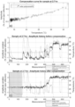
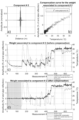
- Figures 7a to 7c shows the case of a sample at 1.83m, which is still dominated by the tail of the reflection from the weld 34 ( Figure 4 ), whereas Figures 8a to 8c shows a sample at 2.71m, which is expected to present reflections from the defect after its introduction at the 380 th measurement.
- third degree polynomials are chosen for the best fit (i.e. , least-squares best fit) for the data available from each sample. Different degrees of polynomial or different types of fitting curve can be used.
- Figures 7b, 7c , 8b and 8c show amplitude variations over time for the two sampling points (locations) considered, comparing the trend available before applying the amplitude compensation with the one obtained after applying it.
- the temperature profile is also overlaid with these trends in order to show how, before applying the amplitude compensation, the amplitudes fluctuate with a strong correlation to temperature.
- Compensation can also be applied to signatures resulting from specialized signal processing techniques, such as ICA.
- ICA specialized signal processing techniques
- the amplitude compensation is applied to a weight function associated with each component.
- the weight functions represent a trend of the particular component over the range of measurements.
- Figure 9a shows a component whose energy is located in a defect-free area of the pipe, just after the weld (near and around the sampling point considered in Figure 7 ).
- a 3 rd degree polynomial is chosen as the best fit (in a least-squares sense) for the data available from its weight function in the baseline region, which was again chosen to include measurements 1 to 145.
- the results shown Figure 9c and 9d resemble the ones shown in Figure 7b and 7c .
- Figure 10a shows a component whose energy represents reflections from the defect and which is in the same area as the sampling point chosen to generate Figure 8 . Again, the results shown in Figures 10c and 10d are in good agreement with the ones shown in Figure 8b and 8c .
- Transduction systems are often operated close to resonance as this gives higher amplitudes.
- a downside is that their frequency response can be temperature sensitive.
- Figure 4 shows results from a piezoelectric system in which the signal generated by the transducer when excited with an 8-cycle windowed toneburst clearly has more than 8 cycles and exhibits a tail. Similar effects are seen with EMAT systems due to the effective presence of an LCR circuit.
- the temperature-dependent resonance behaviour can also be observed in Figure 6 , where the reflection from the weld in the signal recorded at 20°C has an overall higher energy than the one at 36°C.
- three distinct and concurrent effects of such temperature dependent resonance behaviour are usually found, namely different signal peak amplitude, different length of the signal tail after the peak value and signal phase shift.
- DAC distance-amplitude correction
- Figures 11a to 11f illustrate the process by showing it applied to measurements 1 and 145, recorded at temperatures of 36.7 and 13.6 °C respectively. Each of the two signals is first multiplied by its attenuation curve resulting in the signals shown in Figure 11c and 11d , and then normalized to the end pipe reflection shown in Figures 11e and 11f .
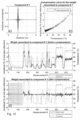
- Figure 12 shows that the application of the compensation process to the weight function of an ICA component (resulting from an ICA being computed on the newly formed dataset) whose energy is in the proximity of the one previously considered to generate Figure 9 successfully suppresses the amplitude variations induced by attenuation.
- the first step is usually to compensate for the temperature-dependent wave speed.
- a typical approach involves the computation of a stretching factor which is used to stretch or compress each signal in a way to get uniform values of wave speed across measurements taken at different temperatures.
- the method described in J. B. Harley and J. M. F. Moura: "Scale transform signal processing for optimal ultrasonic temperature compensation " ibid. is used to obtain the signals plotted in Figure 4 .
- a simulated dataset is created to isolate the desired effect of frequency shift due to signal stretching.
- Such dataset represents an approximately 4.4m long pipe whose only feature is the end pipe reflection being an 8-cycle toneburst at 25.5 kHz, therefore neglecting any modification due to resonance.
- the same temperature profile as in the actual experiment hereinbefore described is retained by imposing to the different signals wave speed values as measured at the different temperatures in the experimental dataset.
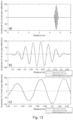
- Figure 13a shows a superposition of all the simulated measurements after signal stretching
- Figure 13b-c presents magnified plots of end pipe reflections from measurements 1 and 145, which clearly illustrate the frequency shift caused by signal stretching.
- Figure 14 demonstrates how the process can successfully eliminate this effect by showing the case of a sampling point at a distance of 4.49m, which is roughly within the third cycle of the end pipe reflection.
- the figure shows how, before applying the amplitude compensation, the measured amplitude varies in strict agreement with the temperature profile, whereas the compensated amplitude trend is basically a flat line on the horizontal axis.
- a subset of amplitude values can be processed. This can help to reduce the amount of computational resources required and/or increase processing speed.
- the subset of data points may take the form of a sub-range of data points corresponding to a region of interest of the structure. The subset may be obtained by sampling every n th amplitude value (where n is a positive integer, such as 2, 3 or 4).
Landscapes
- Physics & Mathematics (AREA)
- General Physics & Mathematics (AREA)
- General Health & Medical Sciences (AREA)
- Pathology (AREA)
- Life Sciences & Earth Sciences (AREA)
- Chemical & Material Sciences (AREA)
- Analytical Chemistry (AREA)
- Biochemistry (AREA)
- Health & Medical Sciences (AREA)
- Immunology (AREA)
- Engineering & Computer Science (AREA)
- Acoustics & Sound (AREA)
- Aviation & Aerospace Engineering (AREA)
- Signal Processing (AREA)
- Investigating Or Analyzing Materials By The Use Of Ultrasonic Waves (AREA)
- Testing Of Devices, Machine Parts, Or Other Structures Thereof (AREA)
- Measurement Of Mechanical Vibrations Or Ultrasonic Waves (AREA)
Claims (18)
- Verfahren, umfassend:Empfangen eines Signals (14), das von Messen einer Struktur (2) unter einem gegebenen Satz von Umgebungs- und/oder Betriebsbedingungen erhalten wird, wobei das Signal einen Satz von Amplitudenwerten umfasst, die jeweils von einer jeweiligen Position in dem Signal abhängen;dadurch gekennzeichnet, dass das Verfahren ferner Folgendes umfasstAnpassen des Amplitudenwertes von jedem von zumindest zwei der Amplitudenwerte unter Verwendung von unterschiedlichen Amplitudenfunktionen gegenüber Satz von Umgebungs- und/oder Betriebsbedingungen, wobei jede Funktion der jeweiligen Position in dem Signal entspricht, von welcher der Amplitudenwert, der durch die Funktion angepasst ist, abhängt, sodass die zumindest zwei Amplitudenwerte unabhängig angepasst werden.
- Verfahren nach Anspruch 1, wobei der Satz von Umgebungsbedingungen eine Temperatur beinhaltet.
- Verfahren nach Anspruch 1 oder 2, wobei das Signal (14) ein eindimensionales Signal oder ein zweidimensionales Signal ist.
- Verfahren nach einem der Ansprüche 1 bis 3, wobei die Position in dem Signal (14) eindeutig einer Position (d) in der Struktur (2) entspricht.
- Verfahren nach einem der Ansprüche 1 bis 4, wobei das Signal (14) von einer Messung einer elastischen Welle der Struktur (2) erhalten wird, wobei optional die elastische Welle eine Ultraschallwelle ist.
- Verfahren nach einem der Ansprüche 1 bis 5, wobei das Signal (14) von einer geführten Wellenmessung der Struktur (2) oder von einer Volumenwellenmessung der Struktur erhalten wird.
- Verfahren nach einem der Ansprüche 1 bis 6, ferner umfassend:
Vorverarbeiten des Signals (14) vor dem Anpassen von jedem der zumindest zwei Amplitudenwerte, wobei optional das Vorverarbeiten des Signals Durchführen von Zeitdehnungskompensation umfasst. - Verfahren nach einem der Ansprüche 1 bis 7, umfassend:
Bestimmen von zumindest einem von den Umgebungs- und/oder Betriebsbedingungen, bei denen das Signal gemessen wird, aus dem Signal. - Verfahren nach Anspruch 8, wobei das Bestimmen des zumindest einen von den Umgebungs- und/oder Betriebsbedingungen, bei denen das Signal gemessen wird, aus dem Signal Folgendes umfasst:
Bestimmen der Temperatur, bei der das Signal gemessen wird, aus dem Signal, und wobei optional das Verfahren ferner Folgendes umfasst:Durchführen einer Zeitdehnungskompensation unter Verwendung eines Skalierungsfaktors (α); undBestimmen einer Temperatur in Abhängigkeit von dem Skalierungsfaktor. - Verfahren nach einem der Ansprüche 1 bis 9, ferner umfassend:Durchführen von Zeitdehnungstemperaturkompensation; undKompensieren von Frequenzverschiebungen aufgrund der Zeitdehnungstemperaturkompensation.
- Verfahren nach einem der Ansprüche 1 bis 10, wobei das Signal (14) eine Komponente oder mehr als eine Komponente eines gemessenen Signals umfasst, wobei optional die Komponente oder die mehr als eine Komponente durch Verarbeiten des gemessenen Signals unter Verwendung eines Signalzerlegungsverfahrens erhalten wird, wie eines Signalzerlegungsverfahrens, das unabhängige Komponentenanalyse umfasst.
- Verfahren, umfassend:
Durchführen des Verfahrens nach einem der Ansprüche 1 bis 11 für eine Vielzahl von Signalen (14), die zu unterschiedlichen Zeiten erhalten werden, und optional Bestimmen, ob es eine Änderung eines angepassten Wertes im Zeitverlauf für eine gegebene Position in dem Signal gibt. - Verfahren nach Anspruch 12, umfassend:Bestimmen, ob sich angepasste Werte für eine gegebene Position im Zeitverlauf monoton ändern; undin Abhängigkeit von einer positiven Bestimmung, Erzeugen eines Signals zum Benachrichtigen eines Benutzers.
- Verfahren nach einem der Ansprüche 1 bis 13, ferner umfassend:
vor dem Empfangen des Signals (14), in einer Kalibrierungsphase:Empfangen einer Vielzahl von Signalen, die von Messen der Struktur (2) bei unterschiedlichen Umgebungs- und/oder Betriebsbedingungen erhalten werden; undErzeugen, für jede Position aus einer Vielzahl von unterschiedlichen Positionen in den Signalen, die während der Kalibrierungsphase empfangen werden, der Amplitudenfunktion gegenüber Satz von Umgebungs- und/oder Betriebsbedingungen, wobei jede Funktion verwendbar ist, um einen Amplitudenwert an einer gegebenen Position in dem Signal (14) anzupassen. - Verfahren nach einem der Ansprüche 1 bis 14, wobei die Struktur (2) ein Rohr, eine Platte, eine Stange oder eine Schiene ist.
- Computerprogramm, das, wenn es durch zumindest einen Prozessor (21) ausgeführt wird, den zumindest einen Prozessor veranlasst, das Verfahren nach einem der Ansprüche 1 bis 15 durchzuführen.
- Vorrichtung (5, 20), umfassend:zumindest einen Prozessor (21); undeinen Speicher (22);wobei der zumindest eine Prozessor konfiguriert ist, um das Verfahren nach einem der Ansprüche 1 bis 15 durchzuführen.
- Inspektionssystem (1), umfassend:einen Sensor (3) zum Messen einer Struktur (2) und Bereitstellen eines Messsignals (19), wobei optional der Sensor permanent an der Struktur installiert ist; undVorrichtung (5; 20) nach Anspruch 17, die konfiguriert ist, um das Messsignal zu empfangen und um das Signal (14) aus dem Messsignal zu erhalten oder um das Messsignal als das Signal zu verwenden.
Applications Claiming Priority (2)
| Application Number | Priority Date | Filing Date | Title |
|---|---|---|---|
| GB1815256.1A GB2577276A (en) | 2018-09-19 | 2018-09-19 | Signal processing |
| PCT/GB2019/051717 WO2020058663A1 (en) | 2018-09-19 | 2019-06-19 | Signal processing |
Publications (2)
| Publication Number | Publication Date |
|---|---|
| EP3853575A1 EP3853575A1 (de) | 2021-07-28 |
| EP3853575B1 true EP3853575B1 (de) | 2024-03-27 |
Family
ID=64013210
Family Applications (1)
| Application Number | Title | Priority Date | Filing Date |
|---|---|---|---|
| EP19734467.4A Active EP3853575B1 (de) | 2018-09-19 | 2019-06-19 | Signalverarbeitung |
Country Status (9)
| Country | Link |
|---|---|
| US (1) | US12117416B2 (de) |
| EP (1) | EP3853575B1 (de) |
| JP (2) | JP7515464B2 (de) |
| KR (1) | KR102747153B1 (de) |
| CN (1) | CN112771360B (de) |
| AU (1) | AU2019341638B2 (de) |
| CA (1) | CA3111362A1 (de) |
| GB (1) | GB2577276A (de) |
| WO (1) | WO2020058663A1 (de) |
Families Citing this family (8)
| Publication number | Priority date | Publication date | Assignee | Title |
|---|---|---|---|---|
| JP7333916B2 (ja) * | 2020-05-20 | 2023-08-28 | 東京瓦斯株式会社 | Ae波検出装置、腐食検知システム、および構造物の腐食検知方法 |
| JP7333915B2 (ja) * | 2020-05-20 | 2023-08-28 | 東京瓦斯株式会社 | 腐食検知システム、および構造物の腐食検知方法 |
| CN112507277B (zh) * | 2020-10-28 | 2024-11-26 | 绍兴精宸智能科技有限公司 | 一种基于电信号的快速振幅预测方法 |
| CN114279554B (zh) * | 2021-11-19 | 2024-06-21 | 国网内蒙古东部电力有限公司电力科学研究院 | 低温振颤传感器的多地同步自适应性能测试方法及系统 |
| US12392756B2 (en) | 2022-01-25 | 2025-08-19 | Herzog Services, Inc. | Roller search unit having integrated digital circuitry for detecting rail defects |
| CN115165270B (zh) * | 2022-06-15 | 2025-03-28 | 西北工业大学 | 多通道颤振试验信号处理的方法和装置 |
| CN115165271B (zh) * | 2022-06-15 | 2025-03-28 | 西北工业大学 | 颤振试验紊流响应信号处理的方法和装置 |
| CN116448888B (zh) * | 2023-03-10 | 2025-10-28 | 北京全路通信信号研究设计院集团有限公司 | 一种变温环境下钢轨超声导波信号处理方法和系统 |
Family Cites Families (16)
| Publication number | Priority date | Publication date | Assignee | Title |
|---|---|---|---|---|
| US7806825B2 (en) * | 2002-11-14 | 2010-10-05 | Team Medical Llc | Diagnostic signal processing method and system |
| JP3747921B2 (ja) * | 2003-06-20 | 2006-02-22 | 株式会社日立製作所 | ガイド波を用いた非破壊検査装置及び非破壊検査方法 |
| US7809513B2 (en) * | 2007-04-16 | 2010-10-05 | Acellent Technologies, Inc. | Environmental change compensation in a structural health monitoring system |
| JP2010267377A (ja) * | 2010-07-29 | 2010-11-25 | Toshiba Corp | 情報記憶媒体、再生方法、記録方法及び再生装置 |
| US8892384B2 (en) * | 2011-06-17 | 2014-11-18 | The Boeing Company | Systems and methods for providing temperature compensation in structural health monitoring |
| US10324068B2 (en) * | 2012-07-19 | 2019-06-18 | Carnegie Mellon University | Temperature compensation in wave-based damage detection systems |
| US20150053009A1 (en) | 2013-08-23 | 2015-02-26 | Fbs, Inc. | Ultrasonic guided wave corrosion detection and monitoring system and method for storage tank floors and other large-scale, complex, plate-like structures |
| US9638588B2 (en) * | 2014-03-07 | 2017-05-02 | Sikorsky Aircraft Corporation | Multifunctional load and damage sensor |
| CN104181237B (zh) | 2014-04-04 | 2017-01-25 | 中国商用飞机有限责任公司北京民用飞机技术研究中心 | 一种结构件探伤监测温度补偿方法及系统 |
| JP2016114570A (ja) | 2014-12-18 | 2016-06-23 | 株式会社日立製作所 | 超音波検査方法および装置 |
| WO2017099852A1 (en) * | 2015-08-12 | 2017-06-15 | Los Alamos National Security, Llc | Detection and monitoring of changes in metallic structures using multimode acoustic signals |
| CN108243132A (zh) * | 2016-12-27 | 2018-07-03 | 华为技术有限公司 | 一种信号调制方法及装置 |
| JP6959598B2 (ja) | 2017-01-23 | 2021-11-02 | 株式会社東芝 | 超音波映像化方法 |
| CN107121497B (zh) * | 2017-06-02 | 2019-10-08 | 东莞理工学院 | 基于Duffing系统的随机共振特性的超声导波检测方法 |
| US11119031B2 (en) * | 2017-08-14 | 2021-09-14 | Quest Integrated, Llc | Corrosion rate monitoring using ultrasound, and associated systems and methods |
| CN107748208B (zh) * | 2017-10-24 | 2019-07-02 | 厦门大学 | 一种基于基准导波信号匹配的温度补偿方法 |
-
2018
- 2018-09-19 GB GB1815256.1A patent/GB2577276A/en not_active Withdrawn
-
2019
- 2019-06-19 US US17/274,740 patent/US12117416B2/en active Active
- 2019-06-19 WO PCT/GB2019/051717 patent/WO2020058663A1/en not_active Ceased
- 2019-06-19 JP JP2021515204A patent/JP7515464B2/ja active Active
- 2019-06-19 EP EP19734467.4A patent/EP3853575B1/de active Active
- 2019-06-19 CN CN201980060773.XA patent/CN112771360B/zh active Active
- 2019-06-19 AU AU2019341638A patent/AU2019341638B2/en active Active
- 2019-06-19 KR KR1020217011623A patent/KR102747153B1/ko active Active
- 2019-06-19 CA CA3111362A patent/CA3111362A1/en active Pending
-
2024
- 2024-02-29 JP JP2024030028A patent/JP2024052904A/ja not_active Withdrawn
Non-Patent Citations (1)
| Title |
|---|
| YINGHUI LU ET AL: "Feature Extraction and Sensor Fusion for Ultrasonic Structural Health Monitoring Under Changing Environmental Conditions", IEEE SENSORS JOURNAL, IEEE, USA, vol. 9, no. 11, 1 November 2009 (2009-11-01), pages 1462 - 1471, XP011277628, ISSN: 1530-437X, DOI: 10.1109/JSEN.2009.2019339 * |
Also Published As
| Publication number | Publication date |
|---|---|
| JP2024052904A (ja) | 2024-04-12 |
| US20220050082A1 (en) | 2022-02-17 |
| JP7515464B2 (ja) | 2024-07-12 |
| GB2577276A (en) | 2020-03-25 |
| CN112771360A (zh) | 2021-05-07 |
| KR20210061408A (ko) | 2021-05-27 |
| AU2019341638A1 (en) | 2021-05-13 |
| CN112771360B (zh) | 2024-11-01 |
| US12117416B2 (en) | 2024-10-15 |
| GB201815256D0 (en) | 2018-10-31 |
| KR102747153B1 (ko) | 2024-12-27 |
| CA3111362A1 (en) | 2020-03-26 |
| WO2020058663A1 (en) | 2020-03-26 |
| JP2022501593A (ja) | 2022-01-06 |
| EP3853575A1 (de) | 2021-07-28 |
| AU2019341638B2 (en) | 2025-07-10 |
Similar Documents
| Publication | Publication Date | Title |
|---|---|---|
| EP3853575B1 (de) | Signalverarbeitung | |
| Mariani et al. | Location specific temperature compensation of guided wave signals in structural health monitoring | |
| US5970434A (en) | Method for determining average wall thickness for pipes and tubes using guided waves | |
| US11092573B2 (en) | Apparatus, systems, and methods for determining nonlinear properties of a material to detect early fatigue or damage | |
| US12235100B2 (en) | Methods and systems for determining a thickness of an elongate or extended structure | |
| KR101716877B1 (ko) | 자가 압전센싱 기반의 비선형 초음파 피로균열 검사 장치 및 방법 | |
| EP4269999A1 (de) | Ultraschalltomographieverfahren und system zur beurteilung von rohrleitungskorrosion | |
| US20090031813A1 (en) | Nondestructive inspection apparatus and nondestructive inspection method using guided wave | |
| Wang et al. | Time-frequency characteristics of longitudinal modes in symmetric mode conversion for defect characterization in guided waves-based pipeline inspection | |
| Ju et al. | Monitoring of corrosion effects in pipes with multi-mode acoustic signals | |
| Miqueleti et al. | Acoustic impedance measurement method using spherical waves | |
| Yoo et al. | Compensation of system nonlinearity in the measurement of acoustic nonlinearity parameters | |
| RU2246724C1 (ru) | Способ ультразвукового контроля качества материала | |
| CN114577911B (zh) | 一种利用相位关系测量材料的声非线性系数的方法 | |
| Senni et al. | Industrial applications: Ultrasonic inspection of large forgings | |
| JP7691950B2 (ja) | 超音波検査方法及び超音波検査装置 | |
| Mariani et al. | Location specific temperature compensation of guided wave signals | |
| CN114577912B (zh) | 一种利用相图测量材料的声非线性系数的方法 | |
| Wilcox et al. | Structural health monitoring using sparse distributed networks of guided wave sensors | |
| McAughey et al. | Thickness measurements of sub-millimetre thickness foils using Lamb wave dispersion | |
| Rosalie et al. | Validation of an optical fibre based plate-wave mode conversion technique for damage detection in plates | |
| CN121721161A (zh) | 小口径管道裂纹缺陷定量检测方法、系统、存储介质和设备 |
Legal Events
| Date | Code | Title | Description |
|---|---|---|---|
| STAA | Information on the status of an ep patent application or granted ep patent |
Free format text: STATUS: UNKNOWN |
|
| STAA | Information on the status of an ep patent application or granted ep patent |
Free format text: STATUS: THE INTERNATIONAL PUBLICATION HAS BEEN MADE |
|
| PUAI | Public reference made under article 153(3) epc to a published international application that has entered the european phase |
Free format text: ORIGINAL CODE: 0009012 |
|
| STAA | Information on the status of an ep patent application or granted ep patent |
Free format text: STATUS: REQUEST FOR EXAMINATION WAS MADE |
|
| 17P | Request for examination filed |
Effective date: 20210219 |
|
| AK | Designated contracting states |
Kind code of ref document: A1 Designated state(s): AL AT BE BG CH CY CZ DE DK EE ES FI FR GB GR HR HU IE IS IT LI LT LU LV MC MK MT NL NO PL PT RO RS SE SI SK SM TR |
|
| DAV | Request for validation of the european patent (deleted) | ||
| DAX | Request for extension of the european patent (deleted) | ||
| STAA | Information on the status of an ep patent application or granted ep patent |
Free format text: STATUS: EXAMINATION IS IN PROGRESS |
|
| 17Q | First examination report despatched |
Effective date: 20220110 |
|
| GRAP | Despatch of communication of intention to grant a patent |
Free format text: ORIGINAL CODE: EPIDOSNIGR1 |
|
| STAA | Information on the status of an ep patent application or granted ep patent |
Free format text: STATUS: GRANT OF PATENT IS INTENDED |
|
| INTG | Intention to grant announced |
Effective date: 20230821 |
|
| P01 | Opt-out of the competence of the unified patent court (upc) registered |
Effective date: 20231113 |
|
| GRAJ | Information related to disapproval of communication of intention to grant by the applicant or resumption of examination proceedings by the epo deleted |
Free format text: ORIGINAL CODE: EPIDOSDIGR1 |
|
| STAA | Information on the status of an ep patent application or granted ep patent |
Free format text: STATUS: EXAMINATION IS IN PROGRESS |
|
| REG | Reference to a national code |
Ref country code: DE Ref legal event code: R079 Free format text: PREVIOUS MAIN CLASS: G01M0005000000 Ipc: G01N0029110000 Ref country code: DE Ref legal event code: R079 Ref document number: 602019049011 Country of ref document: DE Free format text: PREVIOUS MAIN CLASS: G01M0005000000 Ipc: G01N0029110000 |
|
| GRAP | Despatch of communication of intention to grant a patent |
Free format text: ORIGINAL CODE: EPIDOSNIGR1 |
|
| STAA | Information on the status of an ep patent application or granted ep patent |
Free format text: STATUS: GRANT OF PATENT IS INTENDED |
|
| INTC | Intention to grant announced (deleted) | ||
| RIC1 | Information provided on ipc code assigned before grant |
Ipc: G01N 29/04 20060101ALI20240111BHEP Ipc: G01M 5/00 20060101ALI20240111BHEP Ipc: G01N 29/32 20060101ALI20240111BHEP Ipc: G01N 29/11 20060101AFI20240111BHEP |
|
| GRAS | Grant fee paid |
Free format text: ORIGINAL CODE: EPIDOSNIGR3 |
|
| INTG | Intention to grant announced |
Effective date: 20240124 |
|
| GRAA | (expected) grant |
Free format text: ORIGINAL CODE: 0009210 |
|
| STAA | Information on the status of an ep patent application or granted ep patent |
Free format text: STATUS: THE PATENT HAS BEEN GRANTED |
|
| AK | Designated contracting states |
Kind code of ref document: B1 Designated state(s): AL AT BE BG CH CY CZ DE DK EE ES FI FR GB GR HR HU IE IS IT LI LT LU LV MC MK MT NL NO PL PT RO RS SE SI SK SM TR |
|
| REG | Reference to a national code |
Ref country code: GB Ref legal event code: FG4D |
|
| REG | Reference to a national code |
Ref country code: CH Ref legal event code: EP |
|
| REG | Reference to a national code |
Ref country code: DE Ref legal event code: R096 Ref document number: 602019049011 Country of ref document: DE |
|
| REG | Reference to a national code |
Ref country code: IE Ref legal event code: FG4D |
|
| PG25 | Lapsed in a contracting state [announced via postgrant information from national office to epo] |
Ref country code: LT Free format text: LAPSE BECAUSE OF FAILURE TO SUBMIT A TRANSLATION OF THE DESCRIPTION OR TO PAY THE FEE WITHIN THE PRESCRIBED TIME-LIMIT Effective date: 20240327 |
|
| REG | Reference to a national code |
Ref country code: LT Ref legal event code: MG9D |
|
| PG25 | Lapsed in a contracting state [announced via postgrant information from national office to epo] |
Ref country code: GR Free format text: LAPSE BECAUSE OF FAILURE TO SUBMIT A TRANSLATION OF THE DESCRIPTION OR TO PAY THE FEE WITHIN THE PRESCRIBED TIME-LIMIT Effective date: 20240628 |
|
| PG25 | Lapsed in a contracting state [announced via postgrant information from national office to epo] |
Ref country code: HR Free format text: LAPSE BECAUSE OF FAILURE TO SUBMIT A TRANSLATION OF THE DESCRIPTION OR TO PAY THE FEE WITHIN THE PRESCRIBED TIME-LIMIT Effective date: 20240327 Ref country code: RS Free format text: LAPSE BECAUSE OF FAILURE TO SUBMIT A TRANSLATION OF THE DESCRIPTION OR TO PAY THE FEE WITHIN THE PRESCRIBED TIME-LIMIT Effective date: 20240627 |
|
| PG25 | Lapsed in a contracting state [announced via postgrant information from national office to epo] |
Ref country code: RS Free format text: LAPSE BECAUSE OF FAILURE TO SUBMIT A TRANSLATION OF THE DESCRIPTION OR TO PAY THE FEE WITHIN THE PRESCRIBED TIME-LIMIT Effective date: 20240627 Ref country code: NO Free format text: LAPSE BECAUSE OF FAILURE TO SUBMIT A TRANSLATION OF THE DESCRIPTION OR TO PAY THE FEE WITHIN THE PRESCRIBED TIME-LIMIT Effective date: 20240627 Ref country code: LT Free format text: LAPSE BECAUSE OF FAILURE TO SUBMIT A TRANSLATION OF THE DESCRIPTION OR TO PAY THE FEE WITHIN THE PRESCRIBED TIME-LIMIT Effective date: 20240327 Ref country code: HR Free format text: LAPSE BECAUSE OF FAILURE TO SUBMIT A TRANSLATION OF THE DESCRIPTION OR TO PAY THE FEE WITHIN THE PRESCRIBED TIME-LIMIT Effective date: 20240327 Ref country code: GR Free format text: LAPSE BECAUSE OF FAILURE TO SUBMIT A TRANSLATION OF THE DESCRIPTION OR TO PAY THE FEE WITHIN THE PRESCRIBED TIME-LIMIT Effective date: 20240628 Ref country code: FI Free format text: LAPSE BECAUSE OF FAILURE TO SUBMIT A TRANSLATION OF THE DESCRIPTION OR TO PAY THE FEE WITHIN THE PRESCRIBED TIME-LIMIT Effective date: 20240327 Ref country code: BG Free format text: LAPSE BECAUSE OF FAILURE TO SUBMIT A TRANSLATION OF THE DESCRIPTION OR TO PAY THE FEE WITHIN THE PRESCRIBED TIME-LIMIT Effective date: 20240327 |
|
| REG | Reference to a national code |
Ref country code: NL Ref legal event code: MP Effective date: 20240327 |
|
| PG25 | Lapsed in a contracting state [announced via postgrant information from national office to epo] |
Ref country code: SE Free format text: LAPSE BECAUSE OF FAILURE TO SUBMIT A TRANSLATION OF THE DESCRIPTION OR TO PAY THE FEE WITHIN THE PRESCRIBED TIME-LIMIT Effective date: 20240327 Ref country code: LV Free format text: LAPSE BECAUSE OF FAILURE TO SUBMIT A TRANSLATION OF THE DESCRIPTION OR TO PAY THE FEE WITHIN THE PRESCRIBED TIME-LIMIT Effective date: 20240327 |
|
| PG25 | Lapsed in a contracting state [announced via postgrant information from national office to epo] |
Ref country code: NL Free format text: LAPSE BECAUSE OF FAILURE TO SUBMIT A TRANSLATION OF THE DESCRIPTION OR TO PAY THE FEE WITHIN THE PRESCRIBED TIME-LIMIT Effective date: 20240327 |
|
| REG | Reference to a national code |
Ref country code: AT Ref legal event code: MK05 Ref document number: 1670370 Country of ref document: AT Kind code of ref document: T Effective date: 20240327 |
|
| PG25 | Lapsed in a contracting state [announced via postgrant information from national office to epo] |
Ref country code: NL Free format text: LAPSE BECAUSE OF FAILURE TO SUBMIT A TRANSLATION OF THE DESCRIPTION OR TO PAY THE FEE WITHIN THE PRESCRIBED TIME-LIMIT Effective date: 20240327 |
|
| PG25 | Lapsed in a contracting state [announced via postgrant information from national office to epo] |
Ref country code: IS Free format text: LAPSE BECAUSE OF FAILURE TO SUBMIT A TRANSLATION OF THE DESCRIPTION OR TO PAY THE FEE WITHIN THE PRESCRIBED TIME-LIMIT Effective date: 20240727 |
|
| PG25 | Lapsed in a contracting state [announced via postgrant information from national office to epo] |
Ref country code: PT Free format text: LAPSE BECAUSE OF FAILURE TO SUBMIT A TRANSLATION OF THE DESCRIPTION OR TO PAY THE FEE WITHIN THE PRESCRIBED TIME-LIMIT Effective date: 20240729 Ref country code: SM Free format text: LAPSE BECAUSE OF FAILURE TO SUBMIT A TRANSLATION OF THE DESCRIPTION OR TO PAY THE FEE WITHIN THE PRESCRIBED TIME-LIMIT Effective date: 20240327 |
|
| PG25 | Lapsed in a contracting state [announced via postgrant information from national office to epo] |
Ref country code: ES Free format text: LAPSE BECAUSE OF FAILURE TO SUBMIT A TRANSLATION OF THE DESCRIPTION OR TO PAY THE FEE WITHIN THE PRESCRIBED TIME-LIMIT Effective date: 20240327 |
|
| PG25 | Lapsed in a contracting state [announced via postgrant information from national office to epo] |
Ref country code: EE Free format text: LAPSE BECAUSE OF FAILURE TO SUBMIT A TRANSLATION OF THE DESCRIPTION OR TO PAY THE FEE WITHIN THE PRESCRIBED TIME-LIMIT Effective date: 20240327 Ref country code: CZ Free format text: LAPSE BECAUSE OF FAILURE TO SUBMIT A TRANSLATION OF THE DESCRIPTION OR TO PAY THE FEE WITHIN THE PRESCRIBED TIME-LIMIT Effective date: 20240327 |
|
| PG25 | Lapsed in a contracting state [announced via postgrant information from national office to epo] |
Ref country code: AT Free format text: LAPSE BECAUSE OF FAILURE TO SUBMIT A TRANSLATION OF THE DESCRIPTION OR TO PAY THE FEE WITHIN THE PRESCRIBED TIME-LIMIT Effective date: 20240327 |
|
| PG25 | Lapsed in a contracting state [announced via postgrant information from national office to epo] |
Ref country code: PL Free format text: LAPSE BECAUSE OF FAILURE TO SUBMIT A TRANSLATION OF THE DESCRIPTION OR TO PAY THE FEE WITHIN THE PRESCRIBED TIME-LIMIT Effective date: 20240327 |
|
| PG25 | Lapsed in a contracting state [announced via postgrant information from national office to epo] |
Ref country code: SK Free format text: LAPSE BECAUSE OF FAILURE TO SUBMIT A TRANSLATION OF THE DESCRIPTION OR TO PAY THE FEE WITHIN THE PRESCRIBED TIME-LIMIT Effective date: 20240327 |
|
| PG25 | Lapsed in a contracting state [announced via postgrant information from national office to epo] |
Ref country code: SM Free format text: LAPSE BECAUSE OF FAILURE TO SUBMIT A TRANSLATION OF THE DESCRIPTION OR TO PAY THE FEE WITHIN THE PRESCRIBED TIME-LIMIT Effective date: 20240327 Ref country code: SK Free format text: LAPSE BECAUSE OF FAILURE TO SUBMIT A TRANSLATION OF THE DESCRIPTION OR TO PAY THE FEE WITHIN THE PRESCRIBED TIME-LIMIT Effective date: 20240327 Ref country code: RO Free format text: LAPSE BECAUSE OF FAILURE TO SUBMIT A TRANSLATION OF THE DESCRIPTION OR TO PAY THE FEE WITHIN THE PRESCRIBED TIME-LIMIT Effective date: 20240327 Ref country code: PT Free format text: LAPSE BECAUSE OF FAILURE TO SUBMIT A TRANSLATION OF THE DESCRIPTION OR TO PAY THE FEE WITHIN THE PRESCRIBED TIME-LIMIT Effective date: 20240729 Ref country code: PL Free format text: LAPSE BECAUSE OF FAILURE TO SUBMIT A TRANSLATION OF THE DESCRIPTION OR TO PAY THE FEE WITHIN THE PRESCRIBED TIME-LIMIT Effective date: 20240327 Ref country code: IS Free format text: LAPSE BECAUSE OF FAILURE TO SUBMIT A TRANSLATION OF THE DESCRIPTION OR TO PAY THE FEE WITHIN THE PRESCRIBED TIME-LIMIT Effective date: 20240727 Ref country code: ES Free format text: LAPSE BECAUSE OF FAILURE TO SUBMIT A TRANSLATION OF THE DESCRIPTION OR TO PAY THE FEE WITHIN THE PRESCRIBED TIME-LIMIT Effective date: 20240327 Ref country code: EE Free format text: LAPSE BECAUSE OF FAILURE TO SUBMIT A TRANSLATION OF THE DESCRIPTION OR TO PAY THE FEE WITHIN THE PRESCRIBED TIME-LIMIT Effective date: 20240327 Ref country code: CZ Free format text: LAPSE BECAUSE OF FAILURE TO SUBMIT A TRANSLATION OF THE DESCRIPTION OR TO PAY THE FEE WITHIN THE PRESCRIBED TIME-LIMIT Effective date: 20240327 Ref country code: AT Free format text: LAPSE BECAUSE OF FAILURE TO SUBMIT A TRANSLATION OF THE DESCRIPTION OR TO PAY THE FEE WITHIN THE PRESCRIBED TIME-LIMIT Effective date: 20240327 |
|
| REG | Reference to a national code |
Ref country code: DE Ref legal event code: R097 Ref document number: 602019049011 Country of ref document: DE |
|
| PG25 | Lapsed in a contracting state [announced via postgrant information from national office to epo] |
Ref country code: DK Free format text: LAPSE BECAUSE OF FAILURE TO SUBMIT A TRANSLATION OF THE DESCRIPTION OR TO PAY THE FEE WITHIN THE PRESCRIBED TIME-LIMIT Effective date: 20240327 |
|
| PG25 | Lapsed in a contracting state [announced via postgrant information from national office to epo] |
Ref country code: DK Free format text: LAPSE BECAUSE OF FAILURE TO SUBMIT A TRANSLATION OF THE DESCRIPTION OR TO PAY THE FEE WITHIN THE PRESCRIBED TIME-LIMIT Effective date: 20240327 Ref country code: MC Free format text: LAPSE BECAUSE OF FAILURE TO SUBMIT A TRANSLATION OF THE DESCRIPTION OR TO PAY THE FEE WITHIN THE PRESCRIBED TIME-LIMIT Effective date: 20240327 |
|
| REG | Reference to a national code |
Ref country code: CH Ref legal event code: PL |
|
| PLBE | No opposition filed within time limit |
Free format text: ORIGINAL CODE: 0009261 |
|
| STAA | Information on the status of an ep patent application or granted ep patent |
Free format text: STATUS: NO OPPOSITION FILED WITHIN TIME LIMIT |
|
| PG25 | Lapsed in a contracting state [announced via postgrant information from national office to epo] |
Ref country code: LU Free format text: LAPSE BECAUSE OF NON-PAYMENT OF DUE FEES Effective date: 20240619 |
|
| 26N | No opposition filed |
Effective date: 20250103 |
|
| PG25 | Lapsed in a contracting state [announced via postgrant information from national office to epo] |
Ref country code: IE Free format text: LAPSE BECAUSE OF NON-PAYMENT OF DUE FEES Effective date: 20240619 |
|
| PG25 | Lapsed in a contracting state [announced via postgrant information from national office to epo] |
Ref country code: SI Free format text: LAPSE BECAUSE OF FAILURE TO SUBMIT A TRANSLATION OF THE DESCRIPTION OR TO PAY THE FEE WITHIN THE PRESCRIBED TIME-LIMIT Effective date: 20240327 Ref country code: BE Free format text: LAPSE BECAUSE OF NON-PAYMENT OF DUE FEES Effective date: 20240630 Ref country code: CH Free format text: LAPSE BECAUSE OF NON-PAYMENT OF DUE FEES Effective date: 20240630 |
|
| REG | Reference to a national code |
Ref country code: BE Ref legal event code: MM Effective date: 20240630 |
|
| PGFP | Annual fee paid to national office [announced via postgrant information from national office to epo] |
Ref country code: DE Payment date: 20250618 Year of fee payment: 7 |
|
| PGFP | Annual fee paid to national office [announced via postgrant information from national office to epo] |
Ref country code: GB Payment date: 20250616 Year of fee payment: 7 |
|
| PGFP | Annual fee paid to national office [announced via postgrant information from national office to epo] |
Ref country code: FR Payment date: 20250627 Year of fee payment: 7 |
|
| PGFP | Annual fee paid to national office [announced via postgrant information from national office to epo] |
Ref country code: IT Payment date: 20250619 Year of fee payment: 7 |
|
| PG25 | Lapsed in a contracting state [announced via postgrant information from national office to epo] |
Ref country code: CY Free format text: LAPSE BECAUSE OF FAILURE TO SUBMIT A TRANSLATION OF THE DESCRIPTION OR TO PAY THE FEE WITHIN THE PRESCRIBED TIME-LIMIT; INVALID AB INITIO Effective date: 20190619 |
|
| PG25 | Lapsed in a contracting state [announced via postgrant information from national office to epo] |
Ref country code: HU Free format text: LAPSE BECAUSE OF FAILURE TO SUBMIT A TRANSLATION OF THE DESCRIPTION OR TO PAY THE FEE WITHIN THE PRESCRIBED TIME-LIMIT; INVALID AB INITIO Effective date: 20190619 |