EP3853680B1 - Passerelle et procédé destinés à transformer une description d'un équipement de processus industriel en un modèle d'informations de données - Google Patents
Passerelle et procédé destinés à transformer une description d'un équipement de processus industriel en un modèle d'informations de données Download PDFInfo
- Publication number
- EP3853680B1 EP3853680B1 EP19821027.0A EP19821027A EP3853680B1 EP 3853680 B1 EP3853680 B1 EP 3853680B1 EP 19821027 A EP19821027 A EP 19821027A EP 3853680 B1 EP3853680 B1 EP 3853680B1
- Authority
- EP
- European Patent Office
- Prior art keywords
- opc
- eddl
- datalog
- description
- variable
- Prior art date
- Legal status (The legal status is an assumption and is not a legal conclusion. Google has not performed a legal analysis and makes no representation as to the accuracy of the status listed.)
- Active
Links
Images




Classifications
-
- G—PHYSICS
- G05—CONTROLLING; REGULATING
- G05B—CONTROL OR REGULATING SYSTEMS IN GENERAL; FUNCTIONAL ELEMENTS OF SUCH SYSTEMS; MONITORING OR TESTING ARRANGEMENTS FOR SUCH SYSTEMS OR ELEMENTS
- G05B19/00—Program-control systems
- G05B19/02—Program-control systems electric
- G05B19/418—Total factory control, i.e. centrally controlling a plurality of machines, e.g. direct or distributed numerical control [DNC], flexible manufacturing systems [FMS], integrated manufacturing systems [IMS] or computer integrated manufacturing [CIM]
- G05B19/4185—Total factory control, i.e. centrally controlling a plurality of machines, e.g. direct or distributed numerical control [DNC], flexible manufacturing systems [FMS], integrated manufacturing systems [IMS] or computer integrated manufacturing [CIM] characterised by the network communication
-
- G—PHYSICS
- G06—COMPUTING OR CALCULATING; COUNTING
- G06F—ELECTRIC DIGITAL DATA PROCESSING
- G06F16/00—Information retrieval; Database structures therefor; File system structures therefor
- G06F16/90—Details of database functions independent of the retrieved data types
- G06F16/901—Indexing; Data structures therefor; Storage structures
- G06F16/9024—Graphs; Linked lists
-
- G—PHYSICS
- G06—COMPUTING OR CALCULATING; COUNTING
- G06F—ELECTRIC DIGITAL DATA PROCESSING
- G06F16/00—Information retrieval; Database structures therefor; File system structures therefor
- G06F16/20—Information retrieval; Database structures therefor; File system structures therefor of structured data, e.g. relational data
- G06F16/25—Integrating or interfacing systems involving database management systems
- G06F16/258—Data format conversion from or to a database
-
- G—PHYSICS
- G06—COMPUTING OR CALCULATING; COUNTING
- G06F—ELECTRIC DIGITAL DATA PROCESSING
- G06F16/00—Information retrieval; Database structures therefor; File system structures therefor
- G06F16/20—Information retrieval; Database structures therefor; File system structures therefor of structured data, e.g. relational data
- G06F16/28—Databases characterised by their database models, e.g. relational or object models
- G06F16/289—Object oriented databases
-
- G—PHYSICS
- G05—CONTROLLING; REGULATING
- G05B—CONTROL OR REGULATING SYSTEMS IN GENERAL; FUNCTIONAL ELEMENTS OF SUCH SYSTEMS; MONITORING OR TESTING ARRANGEMENTS FOR SUCH SYSTEMS OR ELEMENTS
- G05B2219/00—Program-control systems
- G05B2219/30—Nc systems
- G05B2219/31—From computer integrated manufacturing till monitoring
- G05B2219/31334—Database with devices, configuration, of plant
-
- G—PHYSICS
- G05—CONTROLLING; REGULATING
- G05B—CONTROL OR REGULATING SYSTEMS IN GENERAL; FUNCTIONAL ELEMENTS OF SUCH SYSTEMS; MONITORING OR TESTING ARRANGEMENTS FOR SUCH SYSTEMS OR ELEMENTS
- G05B2219/00—Program-control systems
- G05B2219/30—Nc systems
- G05B2219/32—Operator till task planning
- G05B2219/32142—Define device, module description using xml format file
-
- Y—GENERAL TAGGING OF NEW TECHNOLOGICAL DEVELOPMENTS; GENERAL TAGGING OF CROSS-SECTIONAL TECHNOLOGIES SPANNING OVER SEVERAL SECTIONS OF THE IPC; TECHNICAL SUBJECTS COVERED BY FORMER USPC CROSS-REFERENCE ART COLLECTIONS [XRACs] AND DIGESTS
- Y02—TECHNOLOGIES OR APPLICATIONS FOR MITIGATION OR ADAPTATION AGAINST CLIMATE CHANGE
- Y02P—CLIMATE CHANGE MITIGATION TECHNOLOGIES IN THE PRODUCTION OR PROCESSING OF GOODS
- Y02P90/00—Enabling technologies with a potential contribution to greenhouse gas [GHG] emissions mitigation
- Y02P90/02—Total factory control, e.g. smart factories, flexible manufacturing systems [FMS] or integrated manufacturing systems [IMS]
Definitions
- the present embodiments relate to a gateway for transforming a description of an industrial process equipment into a data information model. More specifically, the present embodiments relate to a transformation of a description of an industrial process equipment into a semantically enriched and graph-based data information model for automation purposes.
- OPC UA An Open Platform Communications Unified Architecture, or OPC UA, provides an architecture for the integration of field devices.
- OPC UA is an industrial standard protocol of the OPC Foundation for manufacturer-independent communication with the purpose of interchanging industrial data, in particular in process automation.
- OPC UA server for device integration based on FDT / DTM (Field Device Tool / Device Type Manager) or EDDL (Electronic Device Description Language) parameterizations is known from a machine translation of the South Korean patent application KR20110054370A into English.
- the patent application is based on the task of enabling the integration of various fieldbus protocols after the conversion from a previous OPC standard to the revised OPC UA (OLE for Process Control Unified Architecture), since the newer OPC UA standard does not have a specific method for integrating devices into knows the OPC UA system.
- OPC UA server is connected with an OPC UA client and a field device.
- a search unit then performs a dynamic search for the field device and a request for a description of the field device.
- An analysis unit is set up to interpret this description of the field device that was received from the external device in response to the request.
- An information model unit is set up to store the description.
- a conversion unit is set up to convert the description of the stored field device into a form that can be used in a web browser-based OPC UA client in accordance with a request from the OPC UA client.
- a communication unit is used to provide the description to the OPC UA client. This communication unit communicates with the field device using a fieldbus or a Profibus protocol.
- the invention is defined by the apparatus of claim 1 and the method of claim 10.
- Industrial processes are complex as they involve technologies of different fields, ranging from mechanics, electronics, communication, and computer science. Further on, different systems play different roles in industrial processes, ranging from field devices, control devices, manufacturing execution systems, and enterprise management systems.
- FIG. 1 shows such a hierarchically layered Automation Pyramid, wherein:
- a data flow is structured by these well-defined layers FLD,CRT,MAN,ENT such that data flows upwards from individual field devices to the enterprise level via control supervision and manufacturing execution systems.
- OPC UA Open Platform Communications Unified Architecture
- OPC Foundation Open Platform Communications Unified Architecture
- OPC UA offers direct data access, regardless of the level of the automation pyramid.
- OPC UA further provides an information model and transport layer communications, where clients at any level of the pyramid can directly access data served by one or more OPC UA servers, hosted at any level. This includes OPC UA servers hosted at the field device level.
- OPC UA imposes a prerequisite in that information of heterogeneous automation devices and systems need to be represented with the OPC UA Information Model - or OPC UA IM - which is a semantically enriched and graph-based data information model for automation purposes.
- EDDL Electronic Device Description Language
- brownfield refers to state-of-the-art-devices operated by a legacy description language which are to be deployed in a more contemporary environment.
- EDDL is not the only example of such legacy description languages.
- Legacy description languages include languages or protocols such as FDT/DTM or Field Device Tool/Device Type Manager, GSD or General Station Description, IO Device Description etc. It is an object of the proposed embodiments to support an integration of field devices operated by such legacy description languages of any kind.
- control is typically localized on the field level FLD or at the control level CRT according to FIG. 1 .
- the control is typically performed during an engineering process wherein automation system parameters of field devices are set and exposed over a controller.
- Such Controllers could then assist to export this information to an OPC UA server located on higher levels of the automation pyramid.
- information from field devices would be indirectly accessible by a server and could be used further above at different levels of the automation pyramid.
- the present embodiments generally propose a gateway for transforming a description of an industrial process equipment into a semantically enriched and graph-based data information model for automation purposes with the goal of enabling industrial process equipment such as brown-field field devices to be used in modern industrial applications.
- the gateway includes a knowledge-based mapping system and allows for a connection to one or more process equipment - particularly field devices - in order to collect information from each field device and exchanging this information with a server or an application on the basis of a semantically enriched and graph-based data information model for automation purposes, such as OPC UA.
- OPC UA For the »upward « exchange of information - e.g. exchange with a server or an application based on a semantically enriched and graph-based data information model - the gateway includes an interface module for accessing the graph-based data information model.
- This interface module is preferably embodied by an OPC UA server operated by and/or on the gateway, such as a gateway-internal OPC UA server.
- FIG. 2 shows a proposed gateway GW connected to one field device FD - or, alternatively to one or more industrial process equipment FD of any kind - and communicating information collected from the description of the industrial process equipment FD to one or more applications, such as a cloud-based application CA, a portable application PA and/or an application MO for asset-monitoring, management, and/or optimization.
- Said applications CA,PA,MO can access the - not shown - description of the industrial process equipment FD over a standard OPC UA server provided by the - not shown - interface module of the gateway GW.
- the knowledge-based mapping MAP of the gateway is detailed as an intermediary model between an input delivering a conventional or legacy field device description FDD - e.g. expressed by the description language EDDL - mapping information from said description to a graph-based data information model and allocating the data information model by a gateway-internal server SRV.
- a mapping knowledge base MKN is used, the details of which will be described further down below.
- the gateway acts in a plug-and-play fashion, i.e., it connects to the field device FD, reads its field device description FDD, and maps field device information (e.g., device parameters) to an OPC UA address space. Device parameters and corresponding values can then be accessed by the gateway-internal server SRV using any - not shown - standard OPC UA client or any - not shown - standard OPC UA server connected to the gateway-internal server SRV.
- field device information e.g., device parameters
- a mapping of information models according to the present embodiments is performed using one or more declarative logic rules or facts for applying a deductive inference mechanism.
- a deductive inference method is described using Datalog as one exemplary programming language for expressing said declarative logic rules.
- a Datalog language section - also referred to as a Datalog program - consists of declarative rules.
- a Datalog system can proof that body is TRUE - as a Boolean TRUE - then it can infer that the head is TRUE as well. This is a mechanism how a Datalog system can derive new knowledge from existing knowledge.
- Datalog programs and Datalog rules are built up from atomic formulas of a type: p(t1,t2,...,tn) wherein p is a predicate symbol and t1, t2, ..., tn denote terms.
- Some predicates have predefined meaning in a Datalog system. They denote a built-in operation, and thus are called built-in predicates.
- built-in predicates and compound terms can be used to handle external calls or functions, which can be used to map EDDL (Electronic Device Description Language) methods and commands into OPC UA methods. Further on, built-in predicates and compound terms can be used to call or execute methods and commands specified in an EDD or Electronic Device Description.
- an atomic formula - or short an atom - is a formula that cannot be divided into strict sub-formulas.
- Literals are positive or negative atoms.
- Terms are constants, variables or compound terms. Variables are denoted with strings consisting of capital letters or beginning with a capital letter - e.g. VAR or Var - and constants are quoted, e.g. "constant_unit”.
- Compound terms implement functions.
- a function is an expression of a type: f(t1,t2,...,tn) wherein f is a function symbol of arity n, and t1,t2,...,tn are terms.
- a fact is a ground atomic formula, e.g. expressed by: p("c1",”c2",...,”cn") wherein “c1",”c2",...,”cn" are constants.
- FIG 4 shows a graphical representation of a declarative logic rule applied to declarative logic facts with the aim of mapping data from one information model to another one.
- Datalog rules can be constructed in such a way that they recursively work with each other to populate complete mapping rules using many individuals, and smaller Datalog rules that define information relationships. As such, in the example, a new Datalog fact with the format of the rule head will be asserted into the database if there are literals matching the body literals' constant terms with the terms also being satisfied as wildcards.
- the OPC UA specification comprises nine OPC UA node classes, including a Base Node class. Each of these node classes has standardized attributes that are stored directly within the node. Each of these node classes can be stored in Datalog using the predicate to specify the node class.
- the inventors have verified a feasible utilization of Datalog in defining relational rules for mapping the facts' term semantics into different facts' semantics, thereby mapping one information model to another, all within a same Datalog database.
- mapping rules are advantageously structured in a hierarchical fashion so as to utilize a re-usability of rules.
- This construction of mapping rules is similar to the art of programming functions used for a modularization of program code, wherein a function is called by a multitude of higher-level function calls rather than being repeatedly coded within the higher level.
- Datalog rules are rather declarative statements, which means they can be interpreted regardless of a position in a program.
- a mapping of typical EDD file attributes is done in a first step, which is followed by a step of mapping the variable itself.
- each EDD file has four top level attributes - manufacturer ID, device type, device revision and the device description revision, see first four lines in the EDDL code shown above - there are four OPC UA property nodes to be attached to the top-level object node representing the EDD file.
- Each property node is constructed from a Variable node that is referenced from its parent object by a reference entitled »HasProperty «.
- Variables are defined using the Variable node class.
- Two types of variables in OPC UA IM are defined: properties and data variables.
- the Variable node is always part of at least one other node.
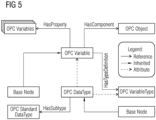
- FIG. 5 shows the resulting model structure modelling the generic variable and top-level attributes of a general EDD file in the graph-based data information model of OPC UA.
- a variable typically describes parameters contained in a field device or in an EDD application.
- a Datalog atomic formula representing an EDDL variable is expressed by:
- EDDL_ID EDDL_ID_1, EDDL_ID_2, EDDL_ID_3, EDDL_ID_4, EDDL_ID_5, EDDL_ID_6 - are used as placeholders for certain OPC UA node identifiers or IDs.
- a Datalog atomic formula representing an OPC UA variable is specified as:
- variable in the OPC UA information model has an ID specified as »EDDL_ID_1 «.
- Browse name, display name and the description is respectively mapped to corresponding EDDL variable values, i.e. EDDL _VariableName, EDDL_LABEL, EDDL_HELP, respectively.
- WriteMask and UserWriteMask are not set in the example above.
- EDDL_ID_2 and EDDL_ID_3 are used respectively.
- opc_BaseNodeClass for opc_UAVariableType needs to be created too.
- the same rule as shown above can be used for this purpose. Only the identifier and the type (UAVariableType instead of UAVariable) need to change:
- OPC_NodeId OPC_NodeId
- OPC_IsAbstract OPC_IsAbstract
- opc_BaseNodeClass for opc_ DataTypeNode needs to be created, the same rule as shown above can be used. Only the identifier and the type (UADataType) need to change.
- OPC UA Variable Node Class EDDL_CONSTANT_UNIT.
- the signature of eddl_Variable has a term called EDDL _CONSTANT_UNIT. This term from an EDDL variable is to be mapped to an OPC UA Property, which is a type of an OPC UA Variable:
- the data type »String « above has its code in the OPC UA information model. Often the code is used in an OPC UA address space to denote a string.
- OPC UA Variable Node Class EDDL_STYLE.
- the signature of eddl_Variable has a term called EDDL_STYLE. This term from an EDDL variable is to be mapped to an OPC UA Property, which is a type of an OPC UA Variable:
- the BaseNodeClass of the property is realized with the following rule:
- EDDL_VALIDITY The signature of eddl_Variable has a term called EDDL_VALIDITY. This term from an EDDL variable is to be mapped to an OPC UA Property, which is a type of an OPC UA Variable:
- the BaseNodeClass of the property can be realized with the following rule.
- actions in EDD such as POST EDIT ACTIONS, POST READ ACTIONS, POST WRITE ACTIONS, PRE EDIT ACTIONS, PRE READ ACTIONS, PRE WRITE ACTIONS etc. can be mapped to OPC UA IM by using Datalog built-in predicates and compound terms. Since they can be used to handle external calls or functions, they can also be used to map EDD actions into OPC UA methods, as well as to call or execute methods and commands specified in an EDD.
- the following section describes a creation of an OPC UA Object node.
- the EDD file attributes of the created OPC UA Object node such as manufacturer ID, device type, device revision and the device description revision, serve as reference.
- the OPC UA Object node is realized with the following rule:
- the top-level file Object must be referenced to the top-level Objects folder in the OPC UA server as this is the root node for an OPC UA server.
- all top-level nodes within an information model should be direct children of this node.
- the reference which accomplishes this is an »Organizes« reference to an in-built node having an ID with a value of 85 or »ObjectsFolder «.
- the OPC UA Reference is represented by the following Datalog atomic formula:
- references between the core Object and the MANUFACTURE ID property Variable node are instantiated. Similar references are instantiated for remaining properties, i.e., DEVICE TYPE, DEVICE REVISION, and DD REVISION:
- the core object is then related to the variable node as expressed by:
- variable node has been defined via the variable type node:
- variable in the EDD file is modeled as a separate variable object, using the basic structure as shown in FIG. 5 , where the variable is based around a Variable object with accompanying property Variable nodes, VariableType node and a simple DataType node. Accordingly, each variable in the EDD file has a number of various properties that are specific to the variable.
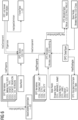
- FIG. 6 shows an extended information model using the standard OPC UA Information Model, and realized by Datalog rules for nodes and references as described above.
- OPC UA EDD File OPC UA Object EDD File Information OPC UA Properties
- OPC UA Variable Base Node, BrowseName LABEL OPC UA Variable Base Node, Display-Name HELP OPC UA Variable Base Node, Description HANDLING OPC UA Variable AccessLevel DEFAULT VALUE OPC UA VariableType Value CLASS OPC UA DataType Base Node, BrowseName TYPE OPC UA DataType, HasSubType reference to respective OPC UA standard data type
- the following section describes an overall system architecture and flow of data in a gateway GW according to an embodiment for transforming a field device description FDD - or more generally: a description of an industrial process equipment - into a OPC UA information model - or more generally: into a semantically enriched and graph-based data information model for automation purposes - with reference to FIG. 7 .
- a parsing module PRS of the gateway GW is reading a field device description FDD of a - not shown - field device or other arbitrary process equipment.
- the field device description FDD is stored in the field device and accessed via a field communication protocol, e.g. the well-known HART (Highway Addressable Remote Transducer) protocol.
- the parsing module PRS is parsing information entities in the field device description FDD of the field device by said field communication protocol.
- the parsed information entities are then transformed into a data object representation - declarative logic facts - which are asserted within a deductive database or knowledge base KNB.
- the parsing module PRS may optionally use an - not shown - accompanying asserter for wrapping the extracted information into Datalog facts and asserting the declarative logic Datalog facts within the knowledge base KNB, e.g. Datalog database KNB.
- the contents of the knowledge base KNB are used for applying mapping rules or mapping knowledge MKN in general to said declarative logic facts using a Datalog Engine DLE.
- the knowledge base KNB or knowledge engine KNB is not only a passively queried database but also acting in a sense of applying rules, mapping facts etc.
- the knowledge base KNB co-operates with the parsing module PRS and a Datalog Engine DLE and may include one or more of these components.
- the knowledge base KNB is loaded with Mapping Knowledge MKN.
- the Mapping Knowledge MKN is operated to deductively map the data objects transformed by the field device description FDD within the knowledge base KNB with a structure to allow them to be later extracted as OPC UA objects. These mapping rules are asserted before any mappings occur, such that they are able to be applied to input information throughout the mapping process.
- Mapping Knowledge MKN can be operated for EDDL and OPC UA IM. Applying similar procedures, it is possible to create Mapping Knowledge MKN for another field device description model, or an extension of this one, for example, if one needs to represent EDD data over OPC UA IM with the semantics from another model, e.g., the NAMUR Open Architecture or NOA model. Applicability of this approach is thus not limited to other standard information models, e.g., IODD or IO Device Description, FDT/DTM14 or Field Device Tool/Device Type Manager, or NOA (NAMUR Open Architecture).
- the functionality of the knowledge base KNB - one core of the gateway GW - has been abstracted away from the system itself. By doing so there is a larger degree of flexibility and portability when implementing application specific mappings. By removing all mapping logic from within the source code, the system's flexibility is bounded only by the modeling abilities of the OPC UA IM.
- Datalog has been chosen as a formalism to implement the proposed mapping method due to the of efficiency of Datalog algorithms and their suitability on even resource constraint devices, e.g., non-expensive IoT devices (Internet of Things) and IoT gateways.
- resource constraint devices e.g., non-expensive IoT devices (Internet of Things) and IoT gateways.
- FIG. 8 shows a flowchart for querying and extracting OPC UA information from the Datalog Engine in order to recursively instantiate all references pointing from a source node.
- a first step 802 the database is queried for a starting base node using a given NodeID.
- a subsequent step 810 the node information is processed, and the current node is marked as known.
- the database is queried for references with a (source) node ID witch matches with the current NodeID.
- the queried reference information is stored.
- a subsequent step 816 for each of the stored reference information one or more NodeIDs are targeted and/or extracted.
- a decision is made of whether a target node is already known or not. Once all nodes are known - represented by a branch Y (»Yes «) pointing vertically upward from decision step 818 - the procedure is completed by step 822.
- step 818 If the referenced target node is not known - represented by a branch N (»No«) of decision step 818 - the flow branches to the step 808, which will be recursively called - see reference sign 820 - with NodeID as target ID.
- the source node would be an OPC UA server's object root node.
- the database will return a list of all references associated with the root node, thus giving a list of all the reference's target node IDs. This returned list can in turn can be recursively processed, allowing for the hierarchical information model of the OPC UA IM to be traversed and processed.
- OPC UA information extracted from the Query Engine is advantageously converted into XML nodes within an XML Schema of OPC UA.
- OPC UA Server Config Generator accomplishes this task, and then passes the information downstream to the OPC UA Server. In this way every standard OPC UA client can access data, which originated as EDD field device descriptions.
Landscapes
- Engineering & Computer Science (AREA)
- Databases & Information Systems (AREA)
- Theoretical Computer Science (AREA)
- General Engineering & Computer Science (AREA)
- Physics & Mathematics (AREA)
- General Physics & Mathematics (AREA)
- Data Mining & Analysis (AREA)
- Software Systems (AREA)
- Manufacturing & Machinery (AREA)
- Quality & Reliability (AREA)
- Automation & Control Theory (AREA)
- Information Retrieval, Db Structures And Fs Structures Therefor (AREA)
- Artificial Intelligence (AREA)
- Computational Linguistics (AREA)
- Evolutionary Computation (AREA)
- Computing Systems (AREA)
- Mathematical Physics (AREA)
Claims (10)
- Passerelle pour transformer une description d'un équipement de processus industriel selon un modèle d'informations de données basé sur graphique(s) et enrichi sémantiquement à des fins d'automatisation à l'intérieur d'un environnement industriel qui supporte une norme industrielle ouverte telle que OPC UA, la passerelle (GW) incluant :- un module d'analyse syntaxique (PRS) pour soumettre à analyse syntaxique des entités d'informations dans la description (FDD) de l'équipement de processus industriel au moyen d'un protocole de communication en champ et pour transformer les entités d'informations qui ont été soumises à analyse syntaxique selon des faits de logique déclarative Datalog et pour implémenter et sauvegarder les faits de logique déclarative Datalog à l'intérieur d'une base de données déductive ;- un moteur de connaissances (KNB) qui est mis en oeuvre en tant que moteur Datalog (DLE) et qui est mis en oeuvre pour utiliser une base de connaissances de mappage (MKN) pour appliquer des règles de mappage auxdits faits de logique déclarative Datalog, d'où il résulte que lesdites règles de mappage sont structurées d'une façon hiérarchique de manière à utiliser une capacité de réutilisation de règles et d'où il résulte que lesdits faits de logique déclarative Datalog sont mappés de façon déductive sur le modèle d'informations de données basé sur graphique(s) ; et- un module d'interface pour accéder au modèle d'informations de données basé sur graphique(s).
- Passerelle selon la revendication 1, dans laquelle le modèle d'informations de données basé sur graphique(s) et enrichi sémantiquement est un modèle d'informations OPC UA.
- Passerelle selon la revendication 2, dans laquelle une règle de mappage est appliquée pour créer une classe de noeud de base OPC UA en utilisant des attributs issus d'une variable correspondante dans la description (FDD) de l'équipement de processus industriel.
- Passerelle selon la revendication 2, dans laquelle une règle de mappage est appliquée pour créer un noeud Objet OPC UA par référence à des attributs correspondants dans la description (FDD) de l'équipement de processus industriel incluant une identification de fabricant, un type de dispositif, une version de dispositif et une version de description de dispositif.
- Passerelle selon la revendication 1, dans laquelle la description (FDD) dudit équipement de processus industriel est exprimée par un moyen d'expression parmi les suivants :- un langage de description de dispositif électronique ou EDDL ;- un protocole outil de dispositif en champ/gestionnaire de type de dispositif ou FDT/DTM ;- une description de station générale ou GSD ; et- une description de dispositif IO.
- Passerelle selon la revendication 1, dans laquelle le module d'interface est un serveur OPC UA interne à la passerelle (ISR) .
- Passerelle selon la revendication 1, dans laquelle le moteur de connaissances (KNB), le module d'analyse syntaxique (PRS) et le moteur Datalog (DLE) sont sensiblement intégrés à l'intérieur d'une seule unité fonctionnelle.
- Passerelle selon la revendication 1, dans laquelle le protocole de communication en champ est un protocole Highway Addressable Remote Transducer ou HART.
- Passerelle selon la revendication 1, incluant au moins une interface d'équipement pour connecter au moins un équipement de processus industriel.
- Procédé pour transformer une description d'un équipement de processus industriel selon un modèle d'informations de données basé sur graphique(s) et enrichi sémantiquement à des fins d'automatisation à l'intérieur d'un environnement industriel qui supporte une norme industrielle ouverte telle que OPC UA, le procédé étant réalisé par une passerelle (GW) et incluant les étapes suivantes :- l'utilisation d'un module d'analyse syntaxique (PRS) pour soumettre à analyse syntaxique des entités d'informations dans la description (FDD) de l'équipement de processus industriel au moyen d'un protocole de communication en champ, pour transformer les entités d'informations qui ont été soumises à analyse syntaxique selon des faits de logique déclarative Datalog et pour implémenter et sauvegarder les faits de logique déclarative Datalog à l'intérieur d'une base de données déductive ;- l'utilisation d'une base de connaissances de mappage dans un moteur de connaissances qui est mis en oeuvre en tant que moteur Datalog pour appliquer des règles de mappage auxdits faits de logique déclarative Datalog, d'où il résulte que lesdites règles de mappage sont structurées d'une façon hiérarchique de manière à utiliser une capacité de réutilisation de règles et d'où il résulte que lesdits faits de logique déclarative Datalog sont mappés de façon déductive sur le modèle d'informations de données basé sur graphique(s) ; et- la fourniture du modèle d'informations de données basé sur graphique(s) par un module d'interface.
Applications Claiming Priority (2)
| Application Number | Priority Date | Filing Date | Title |
|---|---|---|---|
| US16/235,557 US20200210869A1 (en) | 2018-12-28 | 2018-12-28 | Gateway and method for transforming a description of an industrial process equipment into a data information model |
| PCT/EP2019/082917 WO2020135968A1 (fr) | 2018-12-28 | 2019-11-28 | Passerelle et procédé destinés à transformer une description d'un équipement de processus industriel en un modèle d'informations de données |
Publications (3)
| Publication Number | Publication Date |
|---|---|
| EP3853680A1 EP3853680A1 (fr) | 2021-07-28 |
| EP3853680B1 true EP3853680B1 (fr) | 2024-07-17 |
| EP3853680C0 EP3853680C0 (fr) | 2024-07-17 |
Family
ID=68887391
Family Applications (1)
| Application Number | Title | Priority Date | Filing Date |
|---|---|---|---|
| EP19821027.0A Active EP3853680B1 (fr) | 2018-12-28 | 2019-11-28 | Passerelle et procédé destinés à transformer une description d'un équipement de processus industriel en un modèle d'informations de données |
Country Status (4)
| Country | Link |
|---|---|
| US (2) | US20200210869A1 (fr) |
| EP (1) | EP3853680B1 (fr) |
| CN (1) | CN113196192B (fr) |
| WO (1) | WO2020135968A1 (fr) |
Families Citing this family (22)
| Publication number | Priority date | Publication date | Assignee | Title |
|---|---|---|---|---|
| EP3502817A1 (fr) * | 2017-12-19 | 2019-06-26 | ABB Schweiz AG | Procédé pour faciliter les essais et la simulation de système de commande |
| KR102511419B1 (ko) * | 2020-05-11 | 2023-03-17 | 엘에스일렉트릭(주) | 전력 시스템의 데이터 수집 장치 |
| EP3985528A1 (fr) * | 2020-10-16 | 2022-04-20 | ABB Schweiz AG | Négociation de contrats d'information entre les fournisseurs d'information et les consommateurs |
| EP4002030B1 (fr) * | 2020-11-12 | 2025-10-15 | ABB Schweiz AG | Dispositif d'interface pour connecter des contrôleurs de processus à des dispositifs homologues d'opc ua |
| CN112688865B (zh) * | 2020-12-10 | 2022-09-02 | 西安理工大学 | 一种图形化在线建模的opc ua网关的设计方法 |
| CN112597129A (zh) * | 2020-12-21 | 2021-04-02 | 浙江大学 | 基于结构化数据库的opc ua信息模型自动构建方法 |
| CN112702343B (zh) * | 2020-12-22 | 2022-11-22 | 机械工业仪器仪表综合技术经济研究所 | 一种opc ua与mqtt融合方法 |
| CN112860657B (zh) * | 2021-01-14 | 2022-08-02 | 中车青岛四方车辆研究所有限公司 | Tias系统实时数据库地址空间的构建方法及系统 |
| EP4072099B1 (fr) | 2021-04-08 | 2024-07-10 | Siemens Aktiengesellschaft | Système et procédé d'échange de données entre un serveur et un client dans un réseau de données industrielles |
| US12321951B2 (en) | 2021-04-16 | 2025-06-03 | Somos, Inc. | Systems and methods for fraudulent activity detection |
| WO2023004802A1 (fr) * | 2021-07-30 | 2023-02-02 | 西门子(中国)有限公司 | Procédé et dispositif de génération automatique d'un modèle de système de traitement industriel |
| WO2023028886A1 (fr) * | 2021-08-31 | 2023-03-09 | Siemens Aktiengesellschaft | Dispositif de modélisation de données industrielles, procédé et support d'enregistrement lisible par ordinateur |
| CN114465911A (zh) * | 2022-02-10 | 2022-05-10 | 成都阿普奇科技股份有限公司 | 物联网感知设备资源统一描述方法 |
| EP4254086A1 (fr) * | 2022-03-31 | 2023-10-04 | Siemens Aktiengesellschaft | Transformation d'une ontologie en un modèle d'information basé sur des graphes à des fins d'automatisation |
| CN115086362B (zh) * | 2022-05-18 | 2023-08-18 | 中国科学院沈阳自动化研究所 | 异构边缘设备多种复杂模式下的智能传输控制方法 |
| EP4300226A1 (fr) * | 2022-06-30 | 2024-01-03 | Siemens Aktiengesellschaft | Passerelle et procédé de transformation d'un modèle de données d'un équipement de procédé de fabrication |
| US12541555B2 (en) * | 2022-08-22 | 2026-02-03 | Oracle Financial Services Software Limited | Declarative modeling paradigm for graph-database |
| DE102023108656A1 (de) * | 2023-04-04 | 2024-10-10 | Beckhoff Automation Gmbh | Verfahren zum Generieren eines Kommunikationsnetzwerks in einem Automatisierungssystem |
| US12253972B2 (en) | 2023-07-28 | 2025-03-18 | Autodesk, Inc. | Techniques for storing and accessing data using an information model |
| CN121866542A (zh) * | 2023-09-28 | 2026-04-14 | 西门子股份公司 | 工业行为描述文件的处理方法、装置、计算机设备 |
| EP4589396A1 (fr) * | 2024-01-22 | 2025-07-23 | Abb Schweiz Ag | Procédé mis en uvre par ordinateur pour configurer un composant avec un serveur opc ua dans une installation industrielle |
| DE102024201848B4 (de) * | 2024-02-28 | 2025-09-11 | Siemens Aktiengesellschaft | Beschreiben eines Geräts mit großem Sprachmodell |
Family Cites Families (21)
| Publication number | Priority date | Publication date | Assignee | Title |
|---|---|---|---|---|
| US7317952B2 (en) * | 2005-04-07 | 2008-01-08 | Honeywell International Inc. | Managing field devices having different device description specifications in a process control system |
| US20070078540A1 (en) * | 2005-10-05 | 2007-04-05 | Invensys Systems, Inc. | Utility for comparing deployed and archived parameter value sets within a field device editor |
| US8266602B2 (en) | 2006-05-31 | 2012-09-11 | Honeywell International Inc. | Apparatus and method for converting between device description languages in a process control system |
| US7889747B2 (en) * | 2006-05-31 | 2011-02-15 | Honeywell International Inc. | Apparatus, system, and method for integrating a wireless network with wired field devices in a process control system |
| EP1876553A1 (fr) * | 2006-07-07 | 2008-01-09 | Abb Research Ltd. | Procédé et système de graphiques de processus d ingénierie utilisant la reconnaissance de dessin |
| KR101080434B1 (ko) | 2009-11-17 | 2011-11-07 | 울산대학교 산학협력단 | Fdt/dtm과 eddl 기반의 디바이스 통합을 위한 opc ua 서버 |
| US8984533B2 (en) * | 2010-04-15 | 2015-03-17 | Rockwell Automation Technologies, Inc. | Systems and methods for conducting communications among components of multidomain industrial automation system |
| US11068657B2 (en) | 2010-06-28 | 2021-07-20 | Skyscanner Limited | Natural language question answering system and method based on deep semantics |
| DE102010062266A1 (de) * | 2010-12-01 | 2012-06-21 | Codewrights Gmbh | Verfahren zur Realisierung von zumindest einer Zusatzfunktion eines Feldgeräts in der Automatisierungstechnik |
| DE102010063164A1 (de) * | 2010-12-15 | 2012-06-21 | Endress + Hauser Process Solutions Ag | Verfahren zum Integrieren von mindestens einem Feldgerät in ein Netzwerk der Automatisierungstechnik |
| CN103108411B (zh) * | 2011-11-11 | 2016-04-06 | 中国联合网络通信集团有限公司 | 物联网组网方法及设备 |
| US20140040431A1 (en) * | 2012-08-06 | 2014-02-06 | General Electric Company | Systems and methods for an opc ua server |
| KR20150052538A (ko) * | 2013-11-06 | 2015-05-14 | 한국전력공사 | Opc ua 노드 관리 장치 및 그 방법 |
| CN103838921B (zh) | 2014-02-13 | 2015-03-25 | 华北电力大学(保定) | 一种pscad-emtdc仿真模型自动生成方法 |
| US9729580B2 (en) * | 2014-07-30 | 2017-08-08 | Tempered Networks, Inc. | Performing actions via devices that establish a secure, private network |
| DE102015213300A1 (de) * | 2015-07-15 | 2017-01-19 | Siemens Aktiengesellschaft | Verfahren und Vorrichtung zur Erzeugung einer Geräte-spezifischen Kennung und Geräte umfassend einen personalisierten programmierbaren Schaltungsbaustein |
| CN105278960A (zh) * | 2015-10-27 | 2016-01-27 | 航天恒星科技有限公司 | 一种遥感应用中的流程自动化方法及系统 |
| US10359911B2 (en) * | 2016-10-21 | 2019-07-23 | Fisher-Rosemount Systems, Inc. | Apparatus and method for dynamic device description language menus |
| CN107423054B (zh) * | 2017-06-29 | 2021-03-19 | 北京广利核系统工程有限公司 | 基于fpga的自定义图形化算法组态装置、系统和方法 |
| CN107454092B (zh) * | 2017-08-18 | 2021-09-17 | 北京海兰信数据科技股份有限公司 | 一种opcua与dds协议信号转换装置、通信系统及通信方法 |
| CN108459574A (zh) | 2018-03-27 | 2018-08-28 | 重庆邮电大学 | 一种基于语义与opc ua的现场设备信息管理系统 |
-
2018
- 2018-12-28 US US16/235,557 patent/US20200210869A1/en not_active Abandoned
-
2019
- 2019-11-28 EP EP19821027.0A patent/EP3853680B1/fr active Active
- 2019-11-28 US US17/418,767 patent/US12443660B2/en active Active
- 2019-11-28 WO PCT/EP2019/082917 patent/WO2020135968A1/fr not_active Ceased
- 2019-11-28 CN CN201980086722.4A patent/CN113196192B/zh active Active
Also Published As
| Publication number | Publication date |
|---|---|
| US20200210869A1 (en) | 2020-07-02 |
| CN113196192A (zh) | 2021-07-30 |
| CN113196192B (zh) | 2024-07-23 |
| US12443660B2 (en) | 2025-10-14 |
| WO2020135968A1 (fr) | 2020-07-02 |
| US20220058502A1 (en) | 2022-02-24 |
| EP3853680C0 (fr) | 2024-07-17 |
| EP3853680A1 (fr) | 2021-07-28 |
Similar Documents
| Publication | Publication Date | Title |
|---|---|---|
| EP3853680B1 (fr) | Passerelle et procédé destinés à transformer une description d'un équipement de processus industriel en un modèle d'informations de données | |
| Graube et al. | Information models in OPC UA and their advantages and disadvantages | |
| EP3712787B1 (fr) | Procédé de génération d'une description sémantique d'une interaction composite | |
| US12346099B2 (en) | Method for transforming a data model for automation purposes into a target ontology | |
| US10209695B2 (en) | Method and a system for replacing and commissioning of a field device | |
| JP6065008B2 (ja) | 制御装置 | |
| US7702774B2 (en) | Method for operating an object-based configuration system for field devices of automation technology | |
| US7613285B2 (en) | System and method for service-oriented automatic remote control, remote server, and remote control agent | |
| CN112106024A (zh) | 用于在机床的边缘计算设备上部署工业应用的方法和平台 | |
| CN117873943A (zh) | 基于opc ua和本体语义模型的现场设备配置方法 | |
| Weigand et al. | Creating virtual knowledge graphs from software-internal data | |
| Zielstorff et al. | Harmonizing heterogeneity: A novel architecture for legacy system integration with digital twins in industry 4.0 | |
| EP4072099B1 (fr) | Système et procédé d'échange de données entre un serveur et un client dans un réseau de données industrielles | |
| Grothoff et al. | Asset administration shell as integration layer for the orchestration of mixed process and manufacturing plants | |
| EP2772877A1 (fr) | Procédé et système de détection automatique des incohérences dans un modèle de plante | |
| Fernbach et al. | Linked data for building management | |
| EP3812985A1 (fr) | Composant d'automatisation et son procédé de fonctionnement basé sur un modèle d'informations amélioré | |
| Müller et al. | Automatic Transformation of OPC UA Skills Models into Knowledge Graphs. | |
| Müller et al. | Ontology-based communication service for multi-stage production processes | |
| Banerjee et al. | An Electronic Device Description Language based approach for communication with dbms and file system in an industrial automation scenario | |
| Mizutani et al. | Towards Provenance Integration for Field Devices in Industrial IoT Systems | |
| Dai et al. | IEC 61499 ontology model for semantic analysis and code generation | |
| Ahmadon et al. | The Design Once, Provide Anywhere Concept for the Internet of Things Service Implementation | |
| Johansson | Aggregating OPC UA Server for Generic Information Integration | |
| Mahnke et al. | Standard Information Models |
Legal Events
| Date | Code | Title | Description |
|---|---|---|---|
| STAA | Information on the status of an ep patent application or granted ep patent |
Free format text: STATUS: UNKNOWN |
|
| STAA | Information on the status of an ep patent application or granted ep patent |
Free format text: STATUS: THE INTERNATIONAL PUBLICATION HAS BEEN MADE |
|
| PUAI | Public reference made under article 153(3) epc to a published international application that has entered the european phase |
Free format text: ORIGINAL CODE: 0009012 |
|
| STAA | Information on the status of an ep patent application or granted ep patent |
Free format text: STATUS: REQUEST FOR EXAMINATION WAS MADE |
|
| 17P | Request for examination filed |
Effective date: 20210419 |
|
| AK | Designated contracting states |
Kind code of ref document: A1 Designated state(s): AL AT BE BG CH CY CZ DE DK EE ES FI FR GB GR HR HU IE IS IT LI LT LU LV MC MK MT NL NO PL PT RO RS SE SI SK SM TR |
|
| DAV | Request for validation of the european patent (deleted) | ||
| DAX | Request for extension of the european patent (deleted) | ||
| STAA | Information on the status of an ep patent application or granted ep patent |
Free format text: STATUS: EXAMINATION IS IN PROGRESS |
|
| 17Q | First examination report despatched |
Effective date: 20230118 |
|
| GRAP | Despatch of communication of intention to grant a patent |
Free format text: ORIGINAL CODE: EPIDOSNIGR1 |
|
| STAA | Information on the status of an ep patent application or granted ep patent |
Free format text: STATUS: GRANT OF PATENT IS INTENDED |
|
| INTG | Intention to grant announced |
Effective date: 20240315 |
|
| GRAS | Grant fee paid |
Free format text: ORIGINAL CODE: EPIDOSNIGR3 |
|
| GRAA | (expected) grant |
Free format text: ORIGINAL CODE: 0009210 |
|
| STAA | Information on the status of an ep patent application or granted ep patent |
Free format text: STATUS: THE PATENT HAS BEEN GRANTED |
|
| AK | Designated contracting states |
Kind code of ref document: B1 Designated state(s): AL AT BE BG CH CY CZ DE DK EE ES FI FR GB GR HR HU IE IS IT LI LT LU LV MC MK MT NL NO PL PT RO RS SE SI SK SM TR |
|
| REG | Reference to a national code |
Ref country code: CH Ref legal event code: EP |
|
| REG | Reference to a national code |
Ref country code: DE Ref legal event code: R096 Ref document number: 602019055452 Country of ref document: DE |
|
| REG | Reference to a national code |
Ref country code: IE Ref legal event code: FG4D |
|
| U01 | Request for unitary effect filed |
Effective date: 20240717 |
|
| U07 | Unitary effect registered |
Designated state(s): AT BE BG DE DK EE FI FR IT LT LU LV MT NL PT RO SE SI Effective date: 20240902 |
|
| U20 | Renewal fee for the european patent with unitary effect paid |
Year of fee payment: 6 Effective date: 20241118 |
|
| PG25 | Lapsed in a contracting state [announced via postgrant information from national office to epo] |
Ref country code: NO Free format text: LAPSE BECAUSE OF FAILURE TO SUBMIT A TRANSLATION OF THE DESCRIPTION OR TO PAY THE FEE WITHIN THE PRESCRIBED TIME-LIMIT Effective date: 20241017 |
|
| PG25 | Lapsed in a contracting state [announced via postgrant information from national office to epo] |
Ref country code: GR Free format text: LAPSE BECAUSE OF FAILURE TO SUBMIT A TRANSLATION OF THE DESCRIPTION OR TO PAY THE FEE WITHIN THE PRESCRIBED TIME-LIMIT Effective date: 20241018 Ref country code: PL Free format text: LAPSE BECAUSE OF FAILURE TO SUBMIT A TRANSLATION OF THE DESCRIPTION OR TO PAY THE FEE WITHIN THE PRESCRIBED TIME-LIMIT Effective date: 20240717 |
|
| PG25 | Lapsed in a contracting state [announced via postgrant information from national office to epo] |
Ref country code: IS Free format text: LAPSE BECAUSE OF FAILURE TO SUBMIT A TRANSLATION OF THE DESCRIPTION OR TO PAY THE FEE WITHIN THE PRESCRIBED TIME-LIMIT Effective date: 20241117 |
|
| PG25 | Lapsed in a contracting state [announced via postgrant information from national office to epo] |
Ref country code: HR Free format text: LAPSE BECAUSE OF FAILURE TO SUBMIT A TRANSLATION OF THE DESCRIPTION OR TO PAY THE FEE WITHIN THE PRESCRIBED TIME-LIMIT Effective date: 20240717 |
|
| PG25 | Lapsed in a contracting state [announced via postgrant information from national office to epo] |
Ref country code: ES Free format text: LAPSE BECAUSE OF FAILURE TO SUBMIT A TRANSLATION OF THE DESCRIPTION OR TO PAY THE FEE WITHIN THE PRESCRIBED TIME-LIMIT Effective date: 20240717 Ref country code: RS Free format text: LAPSE BECAUSE OF FAILURE TO SUBMIT A TRANSLATION OF THE DESCRIPTION OR TO PAY THE FEE WITHIN THE PRESCRIBED TIME-LIMIT Effective date: 20241017 |
|
| PG25 | Lapsed in a contracting state [announced via postgrant information from national office to epo] |
Ref country code: RS Free format text: LAPSE BECAUSE OF FAILURE TO SUBMIT A TRANSLATION OF THE DESCRIPTION OR TO PAY THE FEE WITHIN THE PRESCRIBED TIME-LIMIT Effective date: 20241017 Ref country code: PL Free format text: LAPSE BECAUSE OF FAILURE TO SUBMIT A TRANSLATION OF THE DESCRIPTION OR TO PAY THE FEE WITHIN THE PRESCRIBED TIME-LIMIT Effective date: 20240717 Ref country code: NO Free format text: LAPSE BECAUSE OF FAILURE TO SUBMIT A TRANSLATION OF THE DESCRIPTION OR TO PAY THE FEE WITHIN THE PRESCRIBED TIME-LIMIT Effective date: 20241017 Ref country code: IS Free format text: LAPSE BECAUSE OF FAILURE TO SUBMIT A TRANSLATION OF THE DESCRIPTION OR TO PAY THE FEE WITHIN THE PRESCRIBED TIME-LIMIT Effective date: 20241117 Ref country code: HR Free format text: LAPSE BECAUSE OF FAILURE TO SUBMIT A TRANSLATION OF THE DESCRIPTION OR TO PAY THE FEE WITHIN THE PRESCRIBED TIME-LIMIT Effective date: 20240717 Ref country code: GR Free format text: LAPSE BECAUSE OF FAILURE TO SUBMIT A TRANSLATION OF THE DESCRIPTION OR TO PAY THE FEE WITHIN THE PRESCRIBED TIME-LIMIT Effective date: 20241018 Ref country code: ES Free format text: LAPSE BECAUSE OF FAILURE TO SUBMIT A TRANSLATION OF THE DESCRIPTION OR TO PAY THE FEE WITHIN THE PRESCRIBED TIME-LIMIT Effective date: 20240717 |
|
| PG25 | Lapsed in a contracting state [announced via postgrant information from national office to epo] |
Ref country code: SM Free format text: LAPSE BECAUSE OF FAILURE TO SUBMIT A TRANSLATION OF THE DESCRIPTION OR TO PAY THE FEE WITHIN THE PRESCRIBED TIME-LIMIT Effective date: 20240717 |
|
| PG25 | Lapsed in a contracting state [announced via postgrant information from national office to epo] |
Ref country code: CZ Free format text: LAPSE BECAUSE OF FAILURE TO SUBMIT A TRANSLATION OF THE DESCRIPTION OR TO PAY THE FEE WITHIN THE PRESCRIBED TIME-LIMIT Effective date: 20240717 |
|
| PG25 | Lapsed in a contracting state [announced via postgrant information from national office to epo] |
Ref country code: SK Free format text: LAPSE BECAUSE OF FAILURE TO SUBMIT A TRANSLATION OF THE DESCRIPTION OR TO PAY THE FEE WITHIN THE PRESCRIBED TIME-LIMIT Effective date: 20240717 |
|
| PLBE | No opposition filed within time limit |
Free format text: ORIGINAL CODE: 0009261 |
|
| STAA | Information on the status of an ep patent application or granted ep patent |
Free format text: STATUS: NO OPPOSITION FILED WITHIN TIME LIMIT |
|
| 26N | No opposition filed |
Effective date: 20250422 |
|
| REG | Reference to a national code |
Ref country code: CH Ref legal event code: PL |
|
| PG25 | Lapsed in a contracting state [announced via postgrant information from national office to epo] |
Ref country code: MC Free format text: LAPSE BECAUSE OF FAILURE TO SUBMIT A TRANSLATION OF THE DESCRIPTION OR TO PAY THE FEE WITHIN THE PRESCRIBED TIME-LIMIT Effective date: 20240717 |
|
| REG | Reference to a national code |
Ref country code: CH Ref legal event code: PL |
|
| GBPC | Gb: european patent ceased through non-payment of renewal fee |
Effective date: 20241128 |
|
| PG25 | Lapsed in a contracting state [announced via postgrant information from national office to epo] |
Ref country code: CH Free format text: LAPSE BECAUSE OF NON-PAYMENT OF DUE FEES Effective date: 20241130 |
|
| PG25 | Lapsed in a contracting state [announced via postgrant information from national office to epo] |
Ref country code: GB Free format text: LAPSE BECAUSE OF NON-PAYMENT OF DUE FEES Effective date: 20241128 |
|
| PG25 | Lapsed in a contracting state [announced via postgrant information from national office to epo] |
Ref country code: IE Free format text: LAPSE BECAUSE OF NON-PAYMENT OF DUE FEES Effective date: 20241128 |
|
| U20 | Renewal fee for the european patent with unitary effect paid |
Year of fee payment: 7 Effective date: 20251120 |
|
| PG25 | Lapsed in a contracting state [announced via postgrant information from national office to epo] |
Ref country code: HU Free format text: LAPSE BECAUSE OF FAILURE TO SUBMIT A TRANSLATION OF THE DESCRIPTION OR TO PAY THE FEE WITHIN THE PRESCRIBED TIME-LIMIT; INVALID AB INITIO Effective date: 20191128 |
|
| PG25 | Lapsed in a contracting state [announced via postgrant information from national office to epo] |
Ref country code: CY Free format text: LAPSE BECAUSE OF FAILURE TO SUBMIT A TRANSLATION OF THE DESCRIPTION OR TO PAY THE FEE WITHIN THE PRESCRIBED TIME-LIMIT; INVALID AB INITIO Effective date: 20191128 |