EP3853696B1 - Rechnerische lösungen in echtzeit für ein dreidimensionales augenverfolgungssystem - Google Patents
Rechnerische lösungen in echtzeit für ein dreidimensionales augenverfolgungssystem Download PDFInfo
- Publication number
- EP3853696B1 EP3853696B1 EP19795404.3A EP19795404A EP3853696B1 EP 3853696 B1 EP3853696 B1 EP 3853696B1 EP 19795404 A EP19795404 A EP 19795404A EP 3853696 B1 EP3853696 B1 EP 3853696B1
- Authority
- EP
- European Patent Office
- Prior art keywords
- eye
- iris
- sensor
- pupil
- plane
- Prior art date
- Legal status (The legal status is an assumption and is not a legal conclusion. Google has not performed a legal analysis and makes no representation as to the accuracy of the status listed.)
- Active
Links
Images





Classifications
-
- G—PHYSICS
- G06—COMPUTING OR CALCULATING; COUNTING
- G06F—ELECTRIC DIGITAL DATA PROCESSING
- G06F3/00—Input arrangements for transferring data to be processed into a form capable of being handled by the computer; Output arrangements for transferring data from processing unit to output unit, e.g. interface arrangements
- G06F3/01—Input arrangements or combined input and output arrangements for interaction between user and computer
- G06F3/011—Arrangements for interaction with the human body, e.g. for user immersion in virtual reality
- G06F3/013—Eye tracking input arrangements
-
- G—PHYSICS
- G02—OPTICS
- G02B—OPTICAL ELEMENTS, SYSTEMS OR APPARATUS
- G02B27/00—Optical systems or apparatus not provided for by any of the groups G02B1/00 - G02B26/00, G02B30/00
- G02B27/0093—Optical systems or apparatus not provided for by any of the groups G02B1/00 - G02B26/00, G02B30/00 with means for monitoring data relating to the user, e.g. head-tracking, eye-tracking
-
- G—PHYSICS
- G02—OPTICS
- G02B—OPTICAL ELEMENTS, SYSTEMS OR APPARATUS
- G02B27/00—Optical systems or apparatus not provided for by any of the groups G02B1/00 - G02B26/00, G02B30/00
- G02B27/01—Head-up displays
- G02B27/017—Head mounted
- G02B27/0172—Head mounted characterised by optical features
-
- G—PHYSICS
- G06—COMPUTING OR CALCULATING; COUNTING
- G06F—ELECTRIC DIGITAL DATA PROCESSING
- G06F17/00—Digital computing or data processing equipment or methods, specially adapted for specific functions
- G06F17/10—Complex mathematical operations
- G06F17/16—Matrix or vector computation, e.g. matrix-matrix or matrix-vector multiplication, matrix factorization
-
- G—PHYSICS
- G06—COMPUTING OR CALCULATING; COUNTING
- G06T—IMAGE DATA PROCESSING OR GENERATION, IN GENERAL
- G06T7/00—Image analysis
- G06T7/20—Analysis of motion
- G06T7/246—Analysis of motion using feature-based methods, e.g. the tracking of corners or segments
- G06T7/251—Analysis of motion using feature-based methods, e.g. the tracking of corners or segments involving models
-
- G—PHYSICS
- G06—COMPUTING OR CALCULATING; COUNTING
- G06T—IMAGE DATA PROCESSING OR GENERATION, IN GENERAL
- G06T7/00—Image analysis
- G06T7/60—Analysis of geometric attributes
-
- G—PHYSICS
- G06—COMPUTING OR CALCULATING; COUNTING
- G06T—IMAGE DATA PROCESSING OR GENERATION, IN GENERAL
- G06T7/00—Image analysis
- G06T7/70—Determining position or orientation of objects or cameras
- G06T7/73—Determining position or orientation of objects or cameras using feature-based methods
- G06T7/75—Determining position or orientation of objects or cameras using feature-based methods involving models
-
- G—PHYSICS
- G06—COMPUTING OR CALCULATING; COUNTING
- G06V—IMAGE OR VIDEO RECOGNITION OR UNDERSTANDING
- G06V40/00—Recognition of biometric, human-related or animal-related patterns in image or video data
- G06V40/10—Human or animal bodies, e.g. vehicle occupants or pedestrians; Body parts, e.g. hands
- G06V40/18—Eye characteristics, e.g. of the iris
-
- A—HUMAN NECESSITIES
- A61—MEDICAL OR VETERINARY SCIENCE; HYGIENE
- A61B—DIAGNOSIS; SURGERY; IDENTIFICATION
- A61B3/00—Apparatus for testing the eyes; Instruments for examining the eyes
- A61B3/0016—Operational features thereof
- A61B3/0025—Operational features thereof characterised by electronic signal processing, e.g. eye models
-
- A—HUMAN NECESSITIES
- A61—MEDICAL OR VETERINARY SCIENCE; HYGIENE
- A61B—DIAGNOSIS; SURGERY; IDENTIFICATION
- A61B3/00—Apparatus for testing the eyes; Instruments for examining the eyes
- A61B3/10—Objective types, i.e. instruments for examining the eyes independent of the patients' perceptions or reactions
- A61B3/11—Objective types, i.e. instruments for examining the eyes independent of the patients' perceptions or reactions for measuring interpupillary distance or diameter of pupils
- A61B3/111—Objective types, i.e. instruments for examining the eyes independent of the patients' perceptions or reactions for measuring interpupillary distance or diameter of pupils for measuring interpupillary distance
-
- G—PHYSICS
- G02—OPTICS
- G02B—OPTICAL ELEMENTS, SYSTEMS OR APPARATUS
- G02B27/00—Optical systems or apparatus not provided for by any of the groups G02B1/00 - G02B26/00, G02B30/00
- G02B27/01—Head-up displays
- G02B27/0101—Head-up displays characterised by optical features
- G02B2027/0138—Head-up displays characterised by optical features comprising image capture systems, e.g. camera
-
- G—PHYSICS
- G02—OPTICS
- G02B—OPTICAL ELEMENTS, SYSTEMS OR APPARATUS
- G02B27/00—Optical systems or apparatus not provided for by any of the groups G02B1/00 - G02B26/00, G02B30/00
- G02B27/01—Head-up displays
- G02B27/0101—Head-up displays characterised by optical features
- G02B2027/014—Head-up displays characterised by optical features comprising information/image processing systems
-
- G—PHYSICS
- G02—OPTICS
- G02B—OPTICAL ELEMENTS, SYSTEMS OR APPARATUS
- G02B27/00—Optical systems or apparatus not provided for by any of the groups G02B1/00 - G02B26/00, G02B30/00
- G02B27/01—Head-up displays
- G02B27/017—Head mounted
- G02B2027/0178—Eyeglass type
-
- G—PHYSICS
- G02—OPTICS
- G02B—OPTICAL ELEMENTS, SYSTEMS OR APPARATUS
- G02B27/00—Optical systems or apparatus not provided for by any of the groups G02B1/00 - G02B26/00, G02B30/00
- G02B27/01—Head-up displays
- G02B27/0179—Display position adjusting means not related to the information to be displayed
- G02B2027/0187—Display position adjusting means not related to the information to be displayed slaved to motion of at least a part of the body of the user, e.g. head, eye
-
- G—PHYSICS
- G02—OPTICS
- G02B—OPTICAL ELEMENTS, SYSTEMS OR APPARATUS
- G02B27/00—Optical systems or apparatus not provided for by any of the groups G02B1/00 - G02B26/00, G02B30/00
- G02B27/01—Head-up displays
-
- G—PHYSICS
- G06—COMPUTING OR CALCULATING; COUNTING
- G06T—IMAGE DATA PROCESSING OR GENERATION, IN GENERAL
- G06T2207/00—Indexing scheme for image analysis or image enhancement
- G06T2207/30—Subject of image; Context of image processing
- G06T2207/30196—Human being; Person
- G06T2207/30201—Face
Definitions
- NED Near-Eye-Display
- CG images computer-generated images
- a NED system may generate composite views to enable a user to visually perceive a CG image superimposed over a physical object that exists within the real-world environment.
- a user's experience is highly dependent on the NED system accurately tracking the user's eye movements.
- the NED system may track an interpupillary distance (IPD) of the user.
- IPD interpupillary distance
- One reason for tracking IPD is so that CG images can be rendered at a suitable separation within the user's field of view.
- the NED system may track a depth at which the user is focusing within the real-world environment.
- One reason for tracking the user's focal depth is because the user may experience motion sickness or vertigo if CG images are rendered at a depth that is different (i.e., closer to/farther from the user) than that which the user is focusing.
- Some conventional eye tracking systems illuminate the user's eyes with near infrared light and then track the user's eye movements by observing reflective patterns that are formed from the near infrared light. For example, upon being illuminated with near infrared light, the eyes may form one or more first Purkinje reflections (e.g., "glints") that are distributed around the iris.
- Conventional eye tracking systems track eye movements (e.g., the user's gaze direction) by analyzing the location(s) of these Purkinje reflections with respect to the center of the pupil.
- convention eye tracking systems estimate the user's line of sight by observing the Purkinje reflections with the addition of head tracking information.
- an accurate estimation of the user's line of sight may be insufficient to accurately determine the depth at which the user is focusing within the real-world environment. This is because the user's line of sight and the user's visual axis (which actually propagates to the user's fovea) only converge at a single depth plane.
- US 2013/0050833 A1 discloses adjusting a see-through, near-eye, mixed reality display device for alignment with an interpupillary distance.
- WO 2015/013022 A1 discloses systems and methods for determining an optical axis vector of an eye in a three-axis coordinate system.
- the present invention provides a computer-implemented method according to claim 1.
- the present invention provides an eye tracking system according to claim 5. Certain more specific aspects of the invention are set out in the dependent claims.
- an exemplary eye tracking system for a NED device includes sensors that are directed toward and angularly offset from a user's eyes in a manner that causes circular features (e.g., irises and/or pupils) of the user's eyes to appear elliptical within sensor planes of the individual sensors.
- an iris and/or pupil of an eye will appear circular when the eye is looked at straight on (i.e., perpendicular to an optical axis of the eye's lens) but elliptical when observed from an angular offset.
- the eye tracking systems and methods disclosed herein exploit these principles to track movements of the user's eyes with a higher degree of accuracy than conventional eye tracking systems.
- Various examples disclosed herein track the user's interpupillary distance (IPD) in real time while the NED device is operating - rather than merely determining the user's IPD at predetermined intervals as conventional eye tracking systems do. Additionally, or alternatively, various examples disclosed herein track the user's visual axes - rather than merely tracking the user's optical axis and/or line of sight as conventional eye tracking systems do. Then, by determining a vergence in space between the visual axes for each of the user's two eyes, such examples calculate the depth in space at which the user is focused with a significantly higher degree of accuracy than conventional eye tracking systems. Accordingly, the disclosed eye tracking systems and methods represents a substantial advance toward preventing a user of a NED device from experiencing motion sickness or vertigo due to CG images being generated in front of or behind the user's accommodation plane (e.g., focal plane).
- IPD interpupillary distance
- An eye tracking system includes sensors that generate eye tracking data associated with one or more substantially circular features of both of a user's eyes.
- substantially circular features include pupils and irises which are generally very close to circular and, therefore, may be modeled as perfect circles for purposes of the calculations described herein.
- the individual sensors have corresponding sensor planes that are angularly skewed with respect to the planes on which the circular features reside (e.g., an Iris-Pupil Plane). Based on the eye tracking data, the eye tracking system determines ellipse parameters for ellipses that result from these sensor planes being angularly skewed from the Iris-Pupil Planes. The eye tracking system tracks both of the user's eyes.
- the eye tracking system determines ellipse parameters that define: (i) first ellipses that correspond to projections of an iris and/or pupil of a right eye onto a first sensor plane; and (ii) second ellipses that correspond to projections of an iris and/or pupil of a left eye onto a second sensor plane.
- the projections of each of the iris(es) and/or pupil(s) onto the corresponding sensor plane(s) pass through a predetermined point such as, for example, an entrance pupil of each corresponding sensor.
- the eye tracking system Based on the ellipse parameters, the eye tracking system then generates propagation data that defines three-dimensional (3D) propagations of the ellipses.
- the 3D propagation data may define a series of lines (e.g., rays) that extend from individual ellipses that are detected on the sensor plane. For example, individual lines of the series of lines may begin on the sensor plane at individual points along a perimeter of a detected ellipse. The individual lines may all commonly propagate from the sensor plane through a predetermined point toward the user's eyes.
- the predetermined point through which all lines of a particular 3D propagation pass is an entrance pupil of a corresponding sensor. Since all of the lines of these 3D propagations extend from the ellipse through the predetermined point, the 3D propagations may be graphically represented as an elliptic cone that extends from the predetermined point toward the eye.
- the eye tracking system utilizes the propagation data to determine pupil orientation parameters that define various characteristics of the user's eye(s).
- Exemplary pupil orientation parameters may define optical axes for one or both of the user's eyes (e.g., an axis of an eye lens), visual axes for one or both of the user's eyes (e.g. axes that extend from the fovea through the lens and into the real-world environment), rotational angles of the user's eyes (e.g. an angle of rotation between a semi-axis of an ellipse and a horizontal axes of the sensor), Iris-Pupil Planes of the user's eyes (e.g.
- the pupil orientation parameters may define various other characteristics of the user's eyes.
- the eye tracking system may utilize the pupil orientation parameters to continually determine of a current (e.g., real time) IPD for a user, i.e. while the NED device is operating. For example, the eye tracking system may dynamically track the center points for each of the user's two eyes and continually calculate and re-calculate the user's interpupillary distance in near real time. Additionally, or alternatively, the eye tracking system may utilize the pupil orientation parameters to determine a vergence of two visual axes (which are different than the optical axis) of the user. For example, the eye tracking system may dynamically track the visual axis of each of the user's two eyes and continually calculate a location in space at which the distance between these two visual axes is the smallest.
- a current e.g., real time
- the eye tracking system may dynamically track the center points for each of the user's two eyes and continually calculate and re-calculate the user's interpupillary distance in near real time.
- the eye tracking system may utilize the pupil orientation
- the visual axes are determined based on visual axis offset data that indicates at least an angular relationship between the optical axis and the visual axis.
- this visual axis offset data may be specifically custom to a particular user and may be determined through a user-specific calibration process. It can be appreciated that although vergence is generally understood as the "point" at which the user's two visual axis intersect, in a practical sense these axes rarely mathematically intersect but rather simply become the closest at the user's accommodation plane. Thus, as described herein the vergence of the visual axes may be determined by calculating a point in space at which the separation between the two visual axes is the least (i.e., wherever the two axes become closest together).
- the pupil orientation parameters are determined by analyzing the propagation data with respect to an ocular rotation model to calculate an orientation of the Iris-pupil plane for an eye, a distance from a predetermined point of the sensor to a center of an entrance pupil of the eye, and/or a radius of the pupil of the eye.
- the ocular rotation model may be usable to model rotation of a circular feature of an eye around that eye's center of rotation.
- the ocular rotation model is (or is based on) an equation that defines coordinates for a circle of a particular radius as that circle is rotated around the center of an eye. It can be appreciated that a circle of a specific radius will mathematically match the "elliptical" 3D propagations only at a single plane.
- utilizing various error minimization algorithms to analyze the propagation data with respect to the ocular rotation model may yield the Iris-Pupil plane's specific location in space and the circular pupil's specific location and rotation thereon.
- error minimization algorithms are described herein, such descriptions are provided for exemplary purposes only and other error minimization algorithms may also be used.
- novel mathematical framework for enabling a variety of eye tracking techniques.
- principle benefits of the novel mathematical framework include that the techniques it enables needn't rely on dedicated light sources to illuminate the eyes (e.g., to form Purkinje reflections from near infrared light) as many conventional eye tracking systems do to observe the eye orientation. Rather, under even dimly lighted environmental circumstances, the eye tracking techniques described herein may deploy cameras to observe a user's eyes under ambient light alone.
- the techniques described herein determine ellipse parameters associated with an angular offset of the sensor planes (e.g., of the cameras) with respect to the Iris-Pupil Planes.
- the ellipse parameters may be utilized to determine various characteristics of the user's eyes such as, for example, directions of optical axes (e.g., an axis of an eye lens), directions of visual axes (e.g. axes that extend from the fovea through the lens and into the real-world environment), rotational angles (e.g.
- Iris-Pupil Planes e.g. a plane on which the pupil resides
- center points for the user's eyes e.g., a point at which the optical axis (or alternatively the visual axis) intersects the Iris-Pupil plane
- any reference to "first,” “second,” etc. items and/or abstract concepts within the Summary and/or Detailed Description is not intended to and should not be construed to necessarily correspond to any reference of "first,” “second,” etc. elements of the claims.
- items and/or abstract concepts such as, for example, three-dimensional (3D) propagations and/or circular features of eyes and/or sensor entrance pupils may be distinguished by numerical designations without such designations corresponding to the claims or even other paragraphs of the Summary and/or Detailed Description.
- any designation of a "first 3D propagation" and "second 3D propagation" of the eye tracking system within any specific paragraph of this the Summary and/or Detailed Description is used solely to distinguish two different 3D propagations of the eye tracking system within that specific paragraph - not any other paragraph and particularly not the claims.
- an exemplary eye tracking system for a NED device includes sensors that are directed toward and angularly offset from a user's eyes in a manner that causes circular features (e.g., irises and/or pupils) of the user's eyes to appear elliptical within sensor planes of the individual sensors.
- circular features e.g., irises and/or pupils
- an iris and/or pupil of an eye will appear circular when the eye is looked at straight on (i.e., perpendicular to an optical axis of the eye's lens) but elliptical when observed from an angular offset.
- the eye tracking systems and methods disclosed herein exploit these principles to track movements of the user's eyes with a higher degree of accuracy than conventional eye tracking systems.
- various examples track the user's visual axes - rather than merely tracking the user's optical axis and/or line of sight as conventional eye tracking systems do. It will be appreciated from the following discussion that determining a vergence in space between the visual axes for each of the user's two eyes provides substantially more actual calculations of the depth in space at which the user is focused than is currently achievable by conventional eye tracking systems.
- the disclosed eye tracking systems and methods therefore represent a substantial advance toward preventing a user of a NED device from experiencing motion sickness or vertigo due to CG images being generated in front of or behind the user's current (e.g., real time) accommodation plane (e.g., focal plane).
- the sensors being cameras that contain one or more lenses that define an entrance pupil that is disposed in front of an image-sensor (e.g., a CMOS sensor).
- the image sensor generates eye tracking data in the form of pixel data that defines images of the user's eyes.
- an appreciation of various aspects of the invention is best gained through a discussion of example in such a context.
- any type of sensor that is suitable for observing a shape and/or orientation of the iris and/or pupil of the user's eye shall be considered variations of the techniques described herein.
- various forms of lenses and sensors may also be suitable for implementing the techniques described herein.
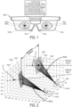
- the NED device 100 includes a pair of sensors 102 that are each directed toward a corresponding eye 104 of a user. More specifically, the illustrated NED device 100 includes a first sensor 102(1) that is angularly offset from and directed toward a right eye 104(R) and also a second sensor 102(1) that is angularly offset from and directed toward a left eye 104(L).
- the right eye 104(R) includes a corresponding pupil 106(R) and a corresponding iris 108(R).
- the left eye 104(L) includes a corresponding pupil 106(L) and a corresponding iris 108(L).
- the sensors 102 can be in any suitable form such as, for example, a non-contact sensor configured to use optical-based tracking (e.g. video camera based and/or some other specially designed optical-sensor-based eye tracking technique) to monitor the one or more physical characteristics of the user's eyes.
- optical-based tracking e.g. video camera based and/or some other specially designed optical-sensor-based eye tracking technique
- Exemplary physical characteristics include, but are not limited to, pupil size, a rate of change of pupil size, gaze direction, and/or a rate of change to a gaze direction.
- FIG. 1 is illustrated from a perspective that is directly in front of the optical axes of the eyes 104 so that the pupils 106 and irises 108 appear perfectly circular. It will be appreciated by one skilled in the art that in humans (and many other vertebrates for that matter) the pupils 106 and irises 108 of the eyes 104 are almost perfect circles. Therefore, in various calculations described below, the pupils 106 and/or irises 108 are mathematically modeled as and/or presumed to be perfectly circular in shape. From the perspective of the individual sensors 102, however, the pupils 106 and irises 108 of the eyes 104 appear to be elliptical as described herein.
- the sensors 102 are angularly offset from the eyes 104 in the sense that the optical axis of each individual sensor 102 is not parallel to the optical axis of the eye 104 it is tracking.
- the position of the sensors 102 shown in FIG. 1 is for illustrative purposes only. It will be appreciated that the techniques described herein can be performed with the sensors 102 being located in a variety of positions with respect to the eyes. As a specific but nonlimiting example, the sensors could be embedded within a lens or other substrate directly in front of the eyes.
- the NED device 100 further includes a controller 110 that is configured to implement the various operations of the methods described herein.
- the controller 110 is communicatively coupled to the sensors 102 to receive eye tracking data that is generated by the sensors 102 in association with the circular features of the eyes.
- the controller 110 may further be communicatively coupled to other componentry of the NED display device 100.
- the controller 110 includes one or more logic devices and one or more computer memory devices storing instructions executable by the logic device(s) to deploy functionalities described herein with relation to the NED device 100.
- the controller 116 comprises one or more processing units 112, one or more computer-readable media 114 for storing an operating system and data such as, for example, eye tracking data, visual axis offset data, application data, etc.
- the computer-readable media 114 further includes an eye tracking engine (e.g., module) configured to receive the eye tracking data from the sensor 102 and, based thereon, determine one or more physical characteristics of the user's eyes using the methods and techniques described herein.
- the components of the NED device 100 are operatively connected, for example, via a bus 120, which can include one or more of a system bus, a data bus, an address bus, a PCI bus, a Mini-PCI bus, and any variety of local, peripheral, and/or independent buses.
- the processing unit(s) 112 can represent, for example, a CPU-type processing unit, a GPU-type processing unit, a field-programmable gate array (FPGA), another class of digital signal processor (DSP), or other hardware logic components that may, in some instances, be driven by a CPU.
- FPGA field-programmable gate array
- DSP digital signal processor
- illustrative types of hardware logic components that can be used include Application-Specific Integrated Circuits (ASICs), Application-Specific Standard Products (ASSPs), System-on-a-Chip Systems (SOCs), Complex Programmable Logic Devices (CPLDs), etc.
- Computer-readable media such as computer-readable media 114, store instructions executable by the processing unit(s).
- Computer-readable media can also store instructions executable by external processing units such as by an external CPU, an external GPU, and/or executable by an external accelerator, such as an FPGA type accelerator, a DSP type accelerator, or any other internal or external accelerator.
- external processing units such as by an external CPU, an external GPU, and/or executable by an external accelerator, such as an FPGA type accelerator, a DSP type accelerator, or any other internal or external accelerator.
- an external accelerator such as an FPGA type accelerator, a DSP type accelerator, or any other internal or external accelerator.
- at least one CPU, GPU, and/or accelerator is incorporated in a computing device, while in some examples one or more of a CPU, GPU, and/or accelerator is external to a computing device.
- Computer-readable media can include computer storage media and/or communication media.
- Computer storage media can include one or more of volatile memory, nonvolatile memory, and/or other persistent and/or auxiliary computer storage media, removable and non-removable computer storage media implemented in any method or technology for storage of information such as computer-readable instructions, data structures, program modules, or other data.
- computer storage media includes tangible and/or physical forms of media included in a device and/or hardware component that is part of a device or external to a device, including but not limited to random access memory (RAM), static random-access memory (SRAM), dynamic random-access memory (DRAM), phase change memory (PCM), read-only memory (ROM), erasable programmable read-only memory (EPROM), electrically erasable programmable read-only memory (EEPROM), flash memory, rotating media, optical cards or other optical storage media, magnetic storage, magnetic cards or other magnetic storage devices or media, solid-state memory devices, storage arrays, network attached storage, storage area networks, hosted computer storage or any other storage memory, storage device, and/or storage medium that can be used to store and maintain information for access by a computing device.
- RAM random access memory
- SRAM static random-access memory
- DRAM dynamic random-access memory
- PCM phase change memory
- ROM read-only memory
- EPROM erasable programmable read-only memory
- EEPROM electrically eras
- communication media can embody computer-readable instructions, data structures, program modules, or other data in a modulated data signal, such as a carrier wave, or other transmission mechanism.
- a modulated data signal such as a carrier wave, or other transmission mechanism.
- computer storage media does not include communication media. That is, computer storage media does not include communications media consisting solely of a modulated data signal, a carrier wave, or a propagated signal, per se.
- the NED device 100 may further include various other components, for example speakers, microphones, accelerometers, gyroscopes, magnetometers, temperature sensors, touch sensors, biometric sensors, other image sensors, energy-storage components (e.g. battery), a communication facility, a GPS receiver, etc.
- various other components for example speakers, microphones, accelerometers, gyroscopes, magnetometers, temperature sensors, touch sensors, biometric sensors, other image sensors, energy-storage components (e.g. battery), a communication facility, a GPS receiver, etc.
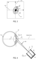
- FIG. 2 illustrated is a pair of three-dimensional (3D) propagations 202 that extend from ellipses 204 that result from circular features (e.g., pupils 106 and/or irises 108) of user's eyes 104 being projected into the sensors 102.
- a first 3D propagation 202(1) extends from a first ellipse 204(1), which is detected at the first sensor 102(1), through a first point P1.
- a second 3D propagation 202(2) extends from a second ellipse 204(2), which is detected at the second sensor 102(2), through a second point P2.
- Each of the 3D propagations 202 extend toward a corresponding Iris-Pupil plane 206 that is angularly offset with respect to the sensors 102.
- the angularly offset nature of the Iris-Pupil planes 206 results in the pupils 106 and irises 108 appearing elliptical from the perspectives of the sensors 102.
- each of the individual 3D propagations 202 may include a series of lines that extend from a perimeter of a corresponding individual ellipse 204 through a corresponding predetermined point and, ultimately, to the perimeter of a circular feature (e.g., pupil 106 or iris 108) that resides within a corresponding Iris-Pupil plane 206.
- the predetermined points (e.g., P1 and P2) may correspond to specific points in space that are measurable in relation to corresponding sensors 102.
- the first predetermined point P1 may correspond to a center of an entrance pupil of the first sensor 102(1) whereas the second predetermined point P2 may correspond to a center of an entrance pupil of the second sensor 102(2).
- P1 may correspond to a point in space at which light rays cross prior to forming an image within the first sensor 102(1) and that P2 may correspond to a point in space at which light rays cross prior to forming an image within the second sensor 102(2).
- these 3D propagations 202 are used to determine pupil orientation parameters that define various characteristics of the user's pupil(s) 106.
- the 3D propagations 202 can be mathematically modeled as elliptical cones. This is because individual ones of the 3D propagations 202 originate at a corresponding ellipse 204 and pass through a singular point. It can further be appreciated that a cross-section of an elliptical cone will be circular in shape if that cross-section is taken at a specific orientation.
- the 3D propagations 202 may enable a determination of the specific orientation of the Iris-Pupil planes 206. Additionally, as described in more detail below, performing various error minimization techniques of the 3D propagations with respect to an ocular rotation model may further enable a determination of the center points of the pupils 106. It can be appreciated that once the location in space of the center point of a pupil 106 and an orientation of an Iris-Pupil plane 206 is known for a particular eye, the optical axis (illustrated as dashed lines for each eye) for that particular eye is also known.
- FIG. 3 illustrated in an exemplary ellipse 204 that is projected from a circular feature of an eye 104 (e.g., an Iris 108) onto a sensor plane 302 of a sensor 102.
- the sensor plane 302 corresponds to a substantially planar surface within the sensor 102 that is angularly skewed with respect to a corresponding Iris-Pupil plane 206 (not shown in FIG. 3 ) so that circular features on the Iris-Pupil plane appear elliptical on the sensor plane 302.
- the sensors 102 are image sensors such as, for example, complementary metal oxide semiconductor (CMOS) sensors and/or charge-coupled device (CCD) sensors.
- CMOS complementary metal oxide semiconductor
- CCD charge-coupled device
- the sensors 102 generate eye tracking data in the form of pixel data that defines images of the eyes. These images may be formed based on ambient light surrounding the user.
- the techniques disclosed herein do not require active emission of near infrared light toward the user's eyes.
- the numerous benefits of the techniques disclosed herein include providing a system that can track the user's eyes using ambient light rather than having to expend battery resources to generate near infrared light.
- the disclosed techniques provide a system that is highly sensitive and accurate in the detection of eye movements (e.g., the systems are sensitive enough to even accurately track saccadic eye movements).
- Semi-axes for the "elliptically shaped" iris 108 and/or pupil 106 are uniquely oriented within the sensor plane 302 for any particular subtended angle of the sensor 102 and rotation of the eye being tracked.
- the size of the semi axes of the elliptically shaped iris 108 and pupil 106 depend on the original size of each and any magnification caused by optical components (e.g., lenses, etc.) of the sensor 102.
- the semi-major axis of the elliptically shaped iris 108 is labelled p ip M and the semi-minor axis of the elliptically shaped iris 108 is labelled p ip m .
- the sensor plane 302 is illustrated with a sensor coordinate system centered thereon.
- the sensor coordinate system includes a vertical y-Axis and a horizontal x-Axis. Additionally, as illustrated, the elliptically shaped iris 108 is rotated an angle ⁇ with respect to the horizontal x-Axis.
- an ellipse 204 that is centered at ( x ⁇ ip d , y ⁇ ip d ) with semi-major axis p ip M and semi-minor axis p ip m and that is also rotated an angle ⁇ with respect to the horizontal x-Axis is given by Equation 1 shown below: E ip i j ⁇ x ⁇ ip d + p ip M cos ⁇ i j cos ⁇ ⁇ p ip m sin ⁇ i j sin ⁇ , y ⁇ ip d + p ip M cos ⁇ i j sin ⁇ ⁇ p ip m sin ⁇ i j cos ⁇
- FIG. 4 illustrated is a side view of a 3D propagation 202 of the ellipse 204 of FIG. 3 from the sensor plane 302 through a predetermined point.
- the predetermined point is labeled r o and is defined as the center of the entrance pupil for the sensor 102.
- r o the predetermined point
- FIG. 4 illustrated is a side view of a 3D propagation 202 of the ellipse 204 of FIG. 3 from the sensor plane 302 through a predetermined point.
- the predetermined point is labeled r o and is defined as the center of the entrance pupil for the sensor 102.
- r o the predetermined point.
- Iris-Pupil plane 206 that falls along the perimeter of the pupil 106 or iris 108.
- the 3D propagation 202 represents the reverse of the projections of the pupil 106 or iris 108 through the point r o and to the sensor plane 302.
- point r o e.g., the center of the entrance pupil of the sensor 102
- r o is a point at which all of the rays of a particular image cross prior to forming an image on the sensor plane 302
- d ipo is the distance from the point r o to the center of the iris/pupil r ⁇
- D cip is the radial distance between the center of the sensor 102 and the ellipse points E ip
- f is the focal length of the sensor 102
- T ⁇ oip (i, j) is the vector going from the points in the ellipse 204 to the point r o .
- the systems described herein may determine one or more of an orientation Rot ( ⁇ , ⁇ ) of the Iris-Pupil plane 206, a radius p ip of the pupil 106 or iris 108 (e.g., whichever circular feature is being observed to perform eye tracking), and the distance d ipo from the point r o to the center r ⁇ ip O of the iris/pupil by analyzing the 3D propagations 202 with respect to an ocular rotation model.
- the ocular rotation model may be usable to model rotation of a circular feature of an eye around that eye's center of rotation r c .
- an ocular rotation model may define coordinates of a circle with a center r ⁇ ip O i j and a radius p ip and that is rotated around the eye's center of rotation r c an elevation angle ⁇ and azimuth angle ⁇ as given by Equation 3 shown below:
- r ⁇ ip r Rot ⁇ ⁇ ⁇ r ⁇ ip O + r ⁇ ip c i j ⁇ r ⁇ c + r ⁇ c
- the center of the iris/pupil circle and the center of rotation of the eye r c are defined from one or more anatomical eye models such as, for example, the Gullstrand model, the Arizona model, the Liou-Brennan model, and/or the Navarro model.
- a user-specific calibration may be performed to complete global minimization of the various parameters used in Equation 3 to customize the ocular rotation model to a specific user.
- the orientation Rot ( ⁇ , ⁇ ) of the Iris-Pupil plane 206, the radius p ip of the pupil 106 or iris 108, and the distance d ipo from the point r o to the center r ⁇ ip O of the iris/pupil are determined by minimizing the error between the 3D propagations 202 of the points detected (e.g., in the sensor plane 302) r ⁇ ip d through the vector T ⁇ cip ( i, j ), and a circle of radius p ip rotated around the eye center r c .
- the systems disclosed herein can dynamically determine an interpupillary distance (IPD) for the user (as shown in FIG. 2 ).
- IPD interpupillary distance
- a NED device 100 includes a first sensor 102(1) that is angularly offset from and directed toward a user's right eye 104(R) and a second sensor 102(2) that is angularly offset from and directed toward a user's left eye 104(L).
- the sensors 102 continually capture images of the pupils 106 and/or irises 108 of the user's eyes.
- FIG. 5A is illustrated from a particular perspective that is directly in front of the user's while the user is looking straight forward.
- the optical axis of each of the eyes 104 is normal to the page and the pupils 106 and irises 108 are illustrated to be perfect circles.
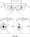
- the pixel data 502 corresponding to each eye defines the pupils 106 and irises 108 as ellipses. As described above, these ellipses correspond to projections of the pupils 106 and irises 108 onto the corresponding sensor planes 302.
- these projections may be defined by a series of rays that all pass through a common point such as the center of the entrance pupil of the sensor 102.
- each of the right eye pixel data 502(1) and the left eye pixel data 502(2) define an image of a corresponding elliptically shaped iris 108.
- Each elliptically shaped iris 108 has a semi-major axis that is labelled p ip M and a semi-minor axis that is labelled p ip m .
- the sensor planes 302 are each illustrated with a corresponding sensor coordinate system centered thereon.
- Each sensor coordinate system includes a vertical y-Axis and a horizontal x-Axis.
- each elliptically shaped iris 108 is aligned with (e.g., centered on and not rotated with respect to) a corresponding sensor coordinate system.
- the perimeters of the right elliptically shaped iris 108(R) and the left elliptically shaped iris 108(L) define a first ellipse 204(1) and a second ellipse 204(2), respectively.
- Each of the ellipses 204 are centered at ( x ⁇ ip d , y ⁇ ip d ) with semi-major axis p ip M and semi-minor axis p ip m and is not rotated respect to the horizontal x-Axis of their corresponding sensor plane 302.
- FIG. 5B exemplary eye tracking data is shown in the form of pixel data 502 that has changed in relation to FIG. 5A due to the user's focus shifting to the left.
- the first ellipse 204(1) that corresponds to the projection of the user's right eye 104(R) has shifted and rotated in relation to the first sensor plane 302(1).
- the semi-minor axis p ip m of the first ellipse 204(1) has lengthened since the right eye's optical axis is directed more towards the sensor 102(1) in FIG. 5B (e.g., after the user looks left) that it was in FIG. 5A .
- the second ellipse 204(2) that corresponds to the projection of the user's left eye 104(L) has shifted and rotated in relation to the second sensor plane 302(2). Additionally, the semi-minor axis p ip m of the second ellipse 204(2) has shortened since the left eye's optical axis is directed more away from the second sensor 102(2) in FIG. 5B (e.g., after the user looks left) that it was in FIG. 5A .
- the eye tracking data for the user's two eyes may be used to continually and dynamically determine the current (e.g., real time) interpupillary distance (IPD) of the user.
- the eye tracking data may be analyzed to determine ellipse parameters that define the ellipses 204 for each eye within the corresponding sensor plane 302. Then, using the techniques described above with respect to equations 1 through 4, the center points r ⁇ ip O for each eye may be determined with respect to the corresponding sensor 102.
- an IPD can be initially determined in association with pixel data that is captured at a first time T 1 .
- an updated IPD can be determined can be determined in association with other pixel data that is captured at a second time T 2 .
- Equation 2 as described above can be modified to specifically place the center of the pupil r ⁇ ip d center in space for both the left and right eyes.
- FIG. 7 illustrated are exemplary positions of a user's right fovea 702(R) and left fovea 702(L) in relation to the optical axes of the user's right eye 104(R) and left eye 104(L), respectively.
- the position of the fovea for each eye is eccentric (e.g., not centrally placed) regarding the optical axis of the corresponding eye.
- the right fovea 702(R) tends to be positioned in the second quadrant for the right eye 104(R) whereas the left fovea 702(L) tends to be positioned in the first quadrant for the left eye 104(L).
- the fovea 702 is the specific region of the retina at which visual acuity is highest due to the user's retinal cones being particularly concentrated in this area. For this reason, the center of the user's field of vision for each eye is focused at the fovea for that eye. The result is that the user's visual axis passes through the center of the fovea 702 so that light from whatever object the user is currently focused on passes through the pupil and lens of the eye before ultimately striking the fovea 702.
- FIG. 8 illustrated is a side view of a user's eye 104 showing how the offset position of the user's fovea in relation to the optical axis results in the visual axis diverging from the optical axis.
- the fovea position being above the optical axis at the back of the user's eye results in the visual axis pointing down slightly.
- the visual axes of the user's eyes will also tent to be pointed inward slightly.
- a line of sight of the user extends from the center of the entrance pupil r ⁇ ip O and intersects the visual axis at a singular intersection point. Accordingly, when the user is focused on an object at a particular accommodation plane, determining the user's line of sight may be adequate to determine where the user is focused. However, since the visual axis will be most closely directed at whatever object the user is focused on regardless of the depth at which the user is focused, conventional eye tracking methods that merely track the user's line of sight are inadequate for determining where the user is focused for all accommodation planes. By dynamically tracking the user's visual axis, the eye tracking systems disclosed herein are able to determine a vergence in space at which the user is currently focused independent of what accommodation plane that vergence falls on.
- convention eye tracking systems estimate the user's line of sight by observing the Purkinje reflections with the addition of head tracking information.
- an accurate estimation of the user's line of sight may be insufficient to accurately determine the depth at which the user is focusing within the real-world environment. This is because the user's line of sight and the user's visual axis (which actually propagates to the user's fovea) only converge at a single depth plane.
- the visual axis is illustrated as a straight and continuous line in FIG.
- the actual optical path of the visual axis is more aptly described as a line connecting the fixation point (at which the user is focused) to the first and second nodal points (not shown in FIG. 8 ) and the user's Fovea.
- a vergence movement comprises the simultaneous movement of a binocular system (e.g., the user's two eyes) in opposite directions to perform a depth operation.
- the eyes rotate toward each other (i.e., the eyes perform a convergence movement).
- the eyes rotate toward away from each other (i.e., the eyes perform a divergence movement).
- the left side of FIG. 9 shows the focus of the user on a house at "Accommodation Plane 1" that is relatively farther from the user than "Accommodation Plane 2.”
- the visual axes each reach a common vergence point that resides on the house whereas a vergence of the lines of sight (which conventional systems track) does not actually represent where the user is focused.
- the left side of FIG. 9 shows the focus of the user on a tree that is at an Accommodation Plane 2 that is relatively closer to the user.
- the visual axes each reach a common vergence point that resides on the tree whereas a vergence of the lines of sight again does not actually represent where the user is focused.
- visual axis offset data is used to continuously track the visual axis of the user's eyes 104.
- the eye tracking systems described herein may continually determine the optical axis and the orientation Rot ( ⁇ , ⁇ ) of the Iris-Pupil plane 206.
- Exemplary visual axis offset data defines a spatial relationship between the optical axis of the eye and/or the orientation Rot ( ⁇ , ⁇ ) of the Iris-Pupil plane 206 of the eye 104.
- the eye tracking systems described herein may utilize the visual axis offset data to calculate the visual axis.
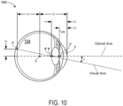
- the anatomical eye model 1000 defines: a horizontal dimension D 1 from the center of the eye 104 (i.e., the point labeled " C ”) to the fovea (i.e., the point labeled " O "); a horizontal dimension D 2 from the center of the eye 104 (i.e., the point labeled " C " ) to the front surface of the cornea; a horizontal dimension D 3 from the front surface of the cornea to a rear surface of the lens of the eye 104 (i.e., the point labeled " N '”); a horizontal dimension D 4 from the front surface of the cornea to a front surface of the lens of the eye 104 (i.e., the point labeled " P' " ); and a vertical dimension D 5 from the center of the eye 104 (i.e., the point labeled " C "
- these or other dimensions may be used to define the visual axis offset data.
- the values for the relevant dimensions may be taken from any variety of suitable models that include, but are not limited to, the Gullstrand model, the Arizona model, the Liou-Brennan model, and/or the Navarro model.
- the visual angle VA ⁇ N ′ line may be represented as a vector that extends from the fovea at point " O " to the point labeled " N'" that represents the rear surface of the lens of the eye 104.
- the visual angle VA ⁇ N ′ line subtends an angle k from the optical axis and can be defined based on Equation 6 below:
- r N' is the image nodal position
- r o is the central position of the fovea 702.
- the angle k ranges between 4 and 8 degrees.
- the various nodal points that are illustrated in FIG. 10 and described throughout this document will change in relative position as the user focuses on object at different accommodation planes.
- the lenses of the eyes are of course caused to change shape.
- the rear surface of the lens may shift between the nodal point labeled " N " and the nodal point labeled " N' " whereas the front surface of the lens may shift between the nodal point labeled " P " and the nodal point labeled " P ' .”
- these changes in the shape of the lens and positions of the nodal points that are triggered by accommodation changes have an insignificant impact on the orientation and placement of the visual axis within the eye.
- the visual axis offset data may define relationships between the optical axis of the eye in a manner that is independent of the current accommodation plane upon which the user is focused.
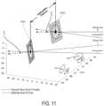
- FIG. 11 illustrates a pair of visual axes that are determinable based on visual axis offset data defining a spatial relationship between the individual visual axes and corresponding optical axes.
- the eye tracking systems described herein can then calculate the visual axes for each eye. These calculations may be done continuously based on visual axis offset data that defines a spatial relationship between the optical axis of the eye and/or the orientation Rot ( ⁇ , ⁇ ) of the Iris-Pupil plane 206 of the eye 104.
- the eye tracking system may then determine the vergence of the visual axes in space.
- the two visual axes will rarely actually converge in space perfectly. This is because although generally modeled as such, the human body does not behave perfectly symmetrically. Rather, there are slight variations in where the two eyes will actually be pointed in a real-life scenario.
- the vergence is calculated by performing minimization techniques with respect to both of the two visual axes.
- the techniques described herein may determine the vergence point to be the point in space at which the visual axes are closest together.
- FIG. 12 illustrated is an exemplary environment 1200 in which a plurality of virtual stimuli 1202 can be sequentially generated at a predetermined accommodation plane for performance of a user-specific calibration process.
- the plurality of virtual stimuli 1202 may be uniformly spaced in a predetermined grid shaped pattern at a predetermined accommodation plane.
- the predetermined accommodation plane may be spaced a predetermined distance in front of the NED device 100 (not shown in FIG. 12 ).
- the predetermined accommodation plane may be spaced a distance of two meters in front of the user.
- the virtual stimuli may be generated at the accommodation plane of two meters by a display element (e.g.
- a waveguide display that is located at a much closer distance to the user's eyes than two meters.
- modern NED devices are capable of rendering images at a plurality of accommodation depths all from a transparent display that is positioned between fifteen and thirty-five millimeters from the user's eyes.
- individual ones of the virtual stimuli 1202 are sequentially rendered (e.g., one at a time) to cause the eyes of the subject to rotate so that the visual axes converge at the currently rendered virtual stimuli. Then, the discrepancy between the orientations Rot ( ⁇ , ⁇ ) of the Iris-Pupil plane 206 as the user's focus changes between the individual stimuli can be exploited to determine the optimum visual axis for that specific user. Stated plainly, the visual axis offset data can be customized for the specific user.
- This type of minimization technique has the advantage that it is convex and that the visual axis can be calculated analytically.
- the values of the center of rotation of the eye r C , and the object nodal point r N can be either introduced following anatomical models like Gullstrand, Arizona, Liou-Brennan or Navarro among others, or otherwise, a global minimization can be performed for custom values.
- FIG. 13 a flow diagram is illustrated of a process 1300 to generate propagation data that defines three-dimensional (3D) propagations from ellipses detected at a sensor plane to determine pupil orientation parameters.
- the process 1300 is illustrated as a collection of blocks in a logical flow graph, which represent a sequence of operations that can be implemented in hardware, software, or a combination thereof.
- the blocks represent computer-executable instructions that, when executed by one or more processors, perform the recited operations.
- computer-executable instructions include routines, programs, objects, components, data structures, and the like that perform or implement particular functions.
- the order in which operations are described is not intended to be construed as a limitation, and any number of the described blocks can be combined in any order and/or in parallel to implement the process. Other processes described throughout this disclosure shall be interpreted accordingly.
- an eye tracking system receives eye tracking data from at least one sensor that is directed toward at least one eye.
- the at least one sensor can be a camera that includes at least one lens through which light passes prior to striking an image sensor (e.g., a CMOS sensor or any other suitable type of image sensor).
- the eye tracking data may be in the form of pixel data that defines an image of circular feature(s) of the at least one eye.
- the eye tracking data includes images of both a right eye and a left eye of a user of a NED device.
- the images may include elliptical representations of the circular features of the eyes due to a sensor plane in each of the sensors being angularly offset from an Iris-Pupil plane of the respective eye that each sensor is tracking.
- the eye tracking system may select between tracking the pupil vs the iris depending on physical characteristics of the user. For example, if the user has very dark irises, there may be very little contrast between the user's pupils and the user's irises. The result of this lack of contrast may be that tracking the user's pupil is impractical.
- the eye tracking system may use the user's iris to perform the eye tracking since there will be greater contrast between the user's iris and the sclera (commonly referred to as the "white of the eye") of the user's eyes than between the user's "dark" iris and the user's dark pupil.
- the eye tracking system determines ellipse parameters for first ellipses that correspond to projections of a circular feature of a first eye (e.g., a right eye) onto a first sensor plane and also for second ellipses that correspond to projections of a circular feature of a second eye (e.g., a left eye) onto a second sensor plane.
- the system may determine, for each of the first ellipse and the second ellipse, a center-point for the ellipse, a semi-major axis of the ellipse, a semi-minor axis of the ellipse, and an angular rotation of the ellipse with respect to a sensor plane.
- the eye tracking system generates propagation data that defines first 3D propagations of the first ellipse back toward the first eye and second 3D propagations of the second ellipse back toward the second eye.
- Each of the 3D propagations may comprise a series of lines that all begin at a point along the perimeter of an ellipse that is detected on a sensor plane and then propagation through a predetermined point back toward the eye of a user.
- the 3D propagations described herein may be generally understood as mathematical representations of rays of light rather than actual projections of light that are emitted from the eye tracking system toward the user.
- a major benefit of the eye tracking systems and techniques disclosed herein is that light need not be emitted for implementations - rather the eye tracking data can be generated based exclusively on ambient light.
- the eye tracking system utilizes the propagation data to determine pupil orientation parameters that define various characteristics of the user's eye(s).
- Exemplary pupil orientation parameters may define optical axes for one or both of the user's eyes (e.g., an axis of an eye lens), visual axes for one or both of the user's eyes (e.g. axes that extend from the fovea through the lens and into the real-world environment), rotational angles of the user's eyes (e.g. an angle of rotation between a semi-axis of an ellipse and a horizontal axes of the sensor), Iris-Pupil Planes of the user's eyes (e.g.
- the pupil orientation parameters may define various other characteristics of the user's eyes.
- the eye tracking system may utilize the pupil orientation parameters and visual axis offset data to determine visual axes that correspond to each of the eyes of the user. Then, the eye tracking system may perform various minimization techniques to determine a vergence between the two visual axes. The determined vergence then represents a focal point within the real-world environment at which the user is currently focused. The vergence may be determined by calculating the point in space at which the two visual axes come the closest to actually converging in pure mathematical terms since in a practical sense the calculated visual axes for a user will rarely (if ever) actually converge.
- novel mathematical framework for enabling a variety of eye tracking techniques.
- principle benefits of the novel mathematical framework include that the techniques it enables needn't rely on dedicated light sources to illuminate the eyes (e.g., to form Purkinje reflections from near infrared light) as many conventional eye tracking systems do to observe the eye orientation. Rather, under even dimly lighted environmental circumstances, the eye tracking techniques described herein may deploy cameras to observe a user's eyes under ambient light alone.
- the techniques described herein determine ellipse parameters associated with an angular offset of the sensor planes (e.g., of the cameras) with respect to the Iris-Pupil Planes.
- the ellipse parameters may be utilized to determine various characteristics of the user's eyes such as, for example, directions of optical axes (e.g., an axis of an eye lens), directions of visual axes (e.g. axes that extend from the fovea through the lens and into the real-world environment), rotational angles (e.g.
- Iris-Pupil Planes e.g. a plane on which the pupil resides
- center points for the user's eyes e.g., a point at which the optical axis (or alternatively the visual axis) intersects the Iris-Pupil plane
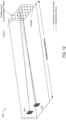
- FIG. 14 illustrated is an exemplary schematic diagram of a model three-dimensional (3D) geometry that corresponds to an analytical solution to the novel mathematical framework described above.
- the analytical solution described in detail below provides techniques for calculating a location and an orientation of the Iris-Pupil Plane in spatial relation to a known position of a camera (e.g., a pinhole-type camera without optical distortion effects, a camera having one or more lenses).
- the analytical solution described in detail below utilizes an assumption of a predetermined presumed iris diameter to effectively reduce the computational complexity of solving the novel mathematical framework described above.
- the predetermined presumed iris diameter is set to an average diameter for a populace of subject users. For example, under circumstances where a populace of subject users have iris diameters ranging from 10.3 mm to 13 mm with an average diameter being 11.8 mm, then presuming the diameter of the iris to be 11.8 mm simplifies the nature of solving the system of equations outlined below. It has been found that presuming an iris diameter yields reasonable eye tracking accuracy for most applications. This is because the iris size is largely consistent across large groups of users with a large number of subjects having iris sizes tightly grouped around the average for the group.
- a circle that is embedded in a plane (e.g., an Iris-Pupil Plane 206) rotating about a center-point can be described trigonometrically as shown in FIG. 14 , where ⁇ v and ⁇ h are the angles of the plane with respect to a reference plane.
- the reference plane may be defined by a mechanical frame at which a camera is mounted to observe an eye of the user.
- the pixels representing the pupil contour (e.g., as shown in FIGS. 5A and 5B ) may be isolated from the rest of the eye.
- these isolated pixels may be fitted to an ellipse.
- the isolated pupil contour may then be fitted to an ellipse (which may of course be tilted within the sensor plane) using a least square algorithm.
- Those pixels that are fitted to the tilted ellipse provide a two-dimensional (2D) distance with respect to the position (e.g., as denoted by r o ) and orientation of the camera.
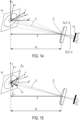
- FIG. 15 illustrated is an exemplary schematic that shows a representation of the Iris-Pupil Plane characteristic vector N ⁇ p within the model 3D geometry that corresponds to the analytical solution to the novel mathematical framework described above.
- FIG. 15 differs from FIG. 14 in that 3 orthonormal vectors (e.g., orthogonal and normalized vectors) that form a base are illustrated.
- vectors T ⁇ od ( i, j ) are shown that join individual pixels on the sensor plane 302 with the exit pupil r o to provide individual geometrical propagations to individual points on the projected ellipse r ⁇ ip d i j .
- a vector T ⁇ od i i j is shown that joins individual pixels of the iris on the sensor plane 302 with the exit pupil r o to provide individual geometrical propagations to individual points on the projected iris ellipse and another vector T ⁇ od i i j is shown that joins individual pixels of the pupil on the sensor plane 302 with the exit pupil r o to provide individual geometrical propagations to individual points on the projected pupil ellipse.
- the exit pupil r o may be defined as the center of a lens.
- the exit pupil r o may be defined as the center of an aperture (e.g., a "pinhole" in lens-less implementations).
- sampling frequency (Hz) of an eye tracking system refers the number of times per second that discrete positions and/or orientations of the eyes are calculated.
- Hz the sampling frequency
- some eye tracking sampling frequencies can range from 60 Hz or lower to even 1200 Hz or more, it is apparent that reducing the computational cost of calculating a single sample measurement yields incremental benefits that continue to increase with increases in the sampling frequency.
- mathematical simplifications to eye tracking problems and methodologies can substantially reduce the computing resources consumed to implement eye tracking techniques.
- the geometry of the analytical solution outlined above can be simplified by considering the radius of the iris p i to be a "known value.”
- the geometry of the analytical solution outlined above can be simplified into a 2D problem based on the points from the iris and/or the pupil.
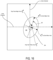
- FIG. 16 illustrated is a schematic diagram of ellipses captured by the camera to define positional relationships between the iris and the pupil for a particular meridian angle.
- the schematic diagram shows linear and angular relationships between the distances of the center of the iris and the center of the ellipse and the distance from the center to the pupil position for that specific meridian.
- the pupil radius p p can be readily calculated using the ellipses that are captured by the camera based on the relationship between the distances of the center of the iris and the center of the ellipse and the distance from the center to the pupil position for that specific meridian (shown in FIG. 16 ).
- the angle ⁇ v may be calculated by solving for the perpendicular meridian as outlined below in Equation 14.
- the angle ⁇ h may be similarly calculated in a similar manner to as described above with respect to the angle ⁇ v .
- the orientation of the Iris-Pupil Plane can be evaluated by projecting the points r M , r m , and r c , outward by the previously calculated distances t m , t m , and t c .
- the respective position in 3D space of r c for each individual eye will determine the dynamic interpupillary distance between the user's eyes.
- the Pupillary axis N ⁇ p can be obtained as the cross product of the normalized vectors N ⁇ Mc and N ⁇ mc .
- the foregoing analytical solution provides a computationally efficient manner to generating real-time solutions to the novel mathematical framework described in relation to FIGS. 1-13 .
- this analytical solution is fast to solve since it enables calculation of the vergence using only measured values, e.g., the semi-major meridian, the semi-minor axis, and the center of the ellipse.
- the novel mathematical framework described above in relation to FIGS. 1-13 can be solved by comparing measured values to a pre-generated lookup table. During this comparison, the particular lookup table entries that produce the minimum error with respect to the measured values are selected as representing the current eye tracking parameters (e.g., gaze direction, etc.) of the user. In this way, the real-time calculations that are performed to implement the lookup-table-based eye tracking solution may be limited to simple error minimization techniques - thereby providing substantial computational efficiency benefits.
- the inputs of the lookup table may be measured parameters of the mathematical framework and the outputs of the table may be modeled parameters of the mathematical framework.
- the inputs may be the eccentricity and center points of the measured ellipses.
- the outputs may be the orientation optical and/or visual axis of the eyes in addition to the dynamic positions of the pupils.
- the camera model may be generated in a suitable mathematical modeling program (e.g., MATLAB by MATHWORKS) based on the nominal (or true) physical dimensions of the cameras with respect to each other and/or a common reference frame.
- the chosen anatomical eye model may also be generated in the mathematical modeling program to define a spatial relationship between the modeled cameras and the corresponding modeled eye.
- An exemplary such "camera-eye model" is illustrated in FIGS. 2 and 11 as described above.
- a plurality of different geometric propagations may be produced - each of which take into account the rays that are launched from the modeled contours of the iris and/or pupil through corresponding predetermined points (e.g., P1 and P2 shown in FIG. 1 ).
- the first predetermined point P1 may correspond to a center of an entrance pupil of the first sensor 102(1)
- the second predetermined point P2 may correspond to a center of an entrance pupil of the second sensor 102(2).
- the rays reach the camera sensor where their positions are transformed onto pixels with the result being a discretized ellipse as shown in FIG. 17 .
- FIG. 17 In particular, FIG.
- FIG. 17 illustrates exemplary modeled sensor data that is generated within a "camera-eye model" by modeling propagations of rays from a modeled iris and/or pupil of the anatomical eye model onto the modeled sensor plane.
- the outer ellipse of the modeled sensor data represents modeled propagations from the iris whereas the inner ellipse of the modeled sensor data represents modeled propagations from the pupil.
- FIG. 18 illustrated is an exemplary "camera-eye model" in which propagations from the modeled iris are generated to the sensor plane at a plurality of different modeled eye orientations.
- each of two anatomical eye models are shown to be directing an optical and/or visual axis toward a currently activated one of a plurality of virtual targets.
- the result of the modeled propagations shown in FIG. 18 may be the modeled sensor data as shown in FIG. 17 . This process is repeated for each of the different virtual targets to generate an individual instance of the modeled sensor data for each individual virtual target.
- the exemplary aggregation of modeled sensor data includes an instance of the modeled sensor data that uniquely corresponds to each individual virtual target as shown in FIG. 18 . That is, each individual one of the many overlapping instances of modeled sensor data represent what measured sensor data is likely to closely resemble in terms of ellipticity parameters and center location under circumstances where a real user's optical and/or visual axis (whichever is used for modeling purposes to generate the lookup table) is oriented and positioned as modeled to generate the modeled sensor data.
- the lookup table represents a modeled sensor data that is generated to cover a plurality of different sensor-to-eye spatial relationships (e.g., positional relationships in terms of both location and orientation).
- the real sensors may be used to generate instances of eye tracking data in the form of pixel data that defines an image of circular feature(s) of the user's eyes.
- the pixel data may include elliptical representations of the circular features of the eyes. These elliptical representations may provide the "measured" inputs to the lookup table which may be, for example, the eccentricity and center points of the measured ellipses. Based on these inputs, error minimization techniques may be performed to determine which generated instance of modeled sensor data most closely matches the inputs that are actually measured via the real sensors.
- Exemplary lookup table outputs may include, but are not limited to, eccentricity, center position, tilting angle, the orientation optical and/or visual axis of the eyes, and/or the dynamic positions of the pupils.
- the appropriate instance of modeled sensor data from the lookup table may be selected based on a neighborhood algorithm.
- a neighborhood algorithm is a relatively simple solution that can be performed very quickly - depending on the density of the sample.
- the closest matching values to the eye tracking data obtained during operation are found in near real time as the minimum square Error or minimum square Euclidean distance from the calculated values ⁇ x ( i ), y ( i ), ⁇ ( i ), ecc ( i ) ⁇ - with the new inputs ⁇ x 0 , y 0 , ⁇ 0 , ecc ⁇ 0 ⁇ being usable in Equation 17 shown below.
- the appropriate instance of modeled sensor data from the lookup table may be selected based on an interpolation algorithm.
- Such an algorithm may provide benefits of increased accuracy while also providing for such accurate results via the user of lookup tables with smaller samples modeled therein.
- Exemplary interpolation algorithms include, but are not limited to, Delaunay decomposition, barycentric coordinates, and so on.
- Equation 12 The novel mathematical framework described above in relation to FIGS. 1-13 can be solved using a minimization solution to calculate the intersection points of the projected camera with a discrete number of planes.
- the first the previous two solutions i.e., the analytical solution
- Equation 12 An examination of Equation 12 above reveals that it includes 3 variables and that 2 of these variables are separable on one side we have the distance d and on the other the angular variables ⁇ ⁇ h , ⁇ v ⁇ that denote the rotations from the world horizontal and vertical axes.
- These variables when expressed in spherical coordinates on terms of the azimuth ⁇ and elevation ⁇ of the eye regarding to the world coordinates produce the characteristic vector N ⁇ p that is defined below in Equation 18.
- the first step is to identify the plane that shows the minimum eccentricity and to use the identified plane to find the distance where the eccentricity is minimum.
- t t c T ⁇ c N ⁇ p T ⁇ od N ⁇ p
- T ⁇ c is the propagation vector of the center of the ellipse
- t c is an arbitrary distance that will be calculated in the second of these two steps.
- the error function picked for minimization is the square of the eccentricity, since the pupil is less elliptical when it is projected onto the right plane Equation 20.
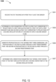
- FIG. 20 a flow diagram is illustrated of a process 2000 to use an eye tracking function that corresponds to a three-dimensional (3D) model for projecting "circular" features through a predetermined point onto a sensor plane.
- the "circular” features may reside on an Iris-Pupil Plane that is angularly offset from the sensor plane such that the "circular” features appear elliptical from the perspective of the sensor.
- a system obtains an eye tracking function.
- the eye tracking function may correspond to various complete solutions to the novel mathematical framework described above.
- the eye tracking function may correspond to the analytical solution described above which is usable to determine pupil orientation parameters that include Iris-Pupil Plane characteristic vectors that are individually calculated based, at least in part, on predetermined presumed iris diameter.
- the eye tracking function may correspond to a lookup table that is pre-generated (i.e., generated prior to the process 2000 being implemented to perform real-time eye tracking) via the "camera-eye model" that is described herein.
- the system receives eye tracking data that is generated in association with at least one circular feature of at least one eye of a user.
- the eye tracking data is in the form of pixel data that defines pixel values that form an image of the at least one eye of the user.
- the system determines ellipse parameters to fit an ellipse to the plurality of pixels.
- the pixels representing the pupil contour that may be isolated at block 2005 may be fitted to a tilted ellipse.
- the isolated pupil contour may then be fitted to a tilted ellipse using a least square algorithm.
- the system inputs the ellipse parameters into the eye tracking function to determine pupil orientation parameters of the at least one eye of the user.
- inputting the ellipse parameters into the eye tracking function outputs yields outputs of Iris-Pupil Plane characteristic vectors that are determined based on projections of the isolated pixels through a predetermined point in front of a sensor plane.
Landscapes
- Engineering & Computer Science (AREA)
- Physics & Mathematics (AREA)
- General Physics & Mathematics (AREA)
- Theoretical Computer Science (AREA)
- General Engineering & Computer Science (AREA)
- Mathematical Physics (AREA)
- Human Computer Interaction (AREA)
- Computer Vision & Pattern Recognition (AREA)
- Mathematical Optimization (AREA)
- Mathematical Analysis (AREA)
- Pure & Applied Mathematics (AREA)
- Data Mining & Analysis (AREA)
- Computational Mathematics (AREA)
- Optics & Photonics (AREA)
- Health & Medical Sciences (AREA)
- Multimedia (AREA)
- Ophthalmology & Optometry (AREA)
- Software Systems (AREA)
- Databases & Information Systems (AREA)
- Algebra (AREA)
- Computing Systems (AREA)
- General Health & Medical Sciences (AREA)
- Life Sciences & Earth Sciences (AREA)
- Geometry (AREA)
- Eye Examination Apparatus (AREA)
- Measurement Of The Respiration, Hearing Ability, Form, And Blood Characteristics Of Living Organisms (AREA)
- Biophysics (AREA)
- Heart & Thoracic Surgery (AREA)
- Medical Informatics (AREA)
- Molecular Biology (AREA)
- Surgery (AREA)
- Animal Behavior & Ethology (AREA)
- Public Health (AREA)
- Veterinary Medicine (AREA)
- Biomedical Technology (AREA)
- Signal Processing (AREA)
Claims (10)
- Computerimplementiertes Verfahren, umfassend:Erhalten (2001) einer Augenverfolgungsfunktion, die einem dreidimensionalen Modell entspricht, zum Projizieren eines ersten kreisförmigen Merkmals (106(R), 108(R)) eines ersten Auges (104) eines Benutzers durch einen ersten vorbestimmten Punkt (P1) auf eine erste Sensorebene (302(1)) und zum Projizieren eines zweiten kreisförmigen Merkmals (106(L), 108(L)) des Benutzers durch einen zweiten vorbestimmten Punkt (P2) auf eine zweite Sensorebene (302(2));Empfangen (2003) von einem ersten Sensor (102(1)), der die erste Sensorebene (302(1)) aufweist, erster Pixeldaten (502(1)), die in Verbindung mit dem ersten kreisförmigen Merkmal (106(R), 108(R)) des ersten Auges (104(R)) des Benutzers erzeugt werden;Empfangen (2003) von einem zweiten Sensor (102(2)), der die zweite Sensorebene (302(2)) aufweist, zweiter Pixeldaten (502(2)), die in Verbindung mit dem zweiten kreisförmigen Merkmal (106(L), 108(L)) des zweiten Auges (104(L)) des Benutzers erzeugt werden;Analysieren (2005) der ersten und zweiten Pixeldaten (502(1), 502(2)), um eine erste Vielzahl von Pixeln zu identifizieren, die dem ersten kreisförmigen Merkmal (106(R), 108(R)) entsprechen, und eine zweite Vielzahl von Pixeln, die dem zweiten kreisförmigen Merkmal (106(L), 108(L)) entsprechen; undBestimmen (2007), basierend auf mindestens den ersten Pixeldaten (502(1)), erster Ellipsenparameter, um eine erste Ellipse (204(1)) an die erste Vielzahl von Pixeln anzupassen, und basierend auf mindestens den zweiten Pixeldaten (502(2)), zweiter Ellipsenparameter, um eine zweite Ellipse (204(2)) an die zweite Vielzahl von Pixeln anzupassen; undEingeben (2009) der ersten und zweiten Ellipsenparameter in die Eye-Tracking-Funktion, um die Parameter der Pupillenausrichtung festzulegen, die die optische Achse und/oder Ausrichtung der Iris-Pupillen-Ebene des ersten Auges (104(R)) und die optische Achse und/oder Ausrichtung der Iris-Pupillen-Ebene des zweiten Auges (104(L)) definieren;dadurch gekennzeichnet, dass das Eingeben der ersten Ellipsenparameter und der zweiten Ellipsenparameter in die Augenverfolgungsfunktion ausgibt:einen ersten Merkmalvektor der Iris-Pupillen-Ebene, der senkrecht zur Iris-Pupillen-Ebene des ersten Auges steht und basierend auf dreidimensionalen Ausbreitungen (202(1)) der ersten Vielzahl von Pixeln mit den dreidimensionalen Ausbreitungen, die mathematisch als elliptischer Kegel modelliert sind und sich von der ersten Vielzahl von Pixeln der ersten Ellipse durch den ersten vorbestimmten Punkt (P1) in Richtung des ersten Auges erstrecken, festgelegt wird, wobei der erste vorbestimmte Punkt (P1) vor der ersten Sensorebene (302(1)) liegt, undeinen ersten Merkmalvektor der Iris-Pupillen-Ebene, der senkrecht zur Iris-Pupillen-Ebene des zweiten Auges steht und basierend auf dreidimensionalen Ausbreitungen (202(2)) der zweiten Vielzahl von Pixeln mit den dreidimensionalen Ausbreitungen, die mathematisch als elliptischer Kegel modelliert sind und sich von der zweiten Vielzahl von Pixeln der zweiten Ellipse durch den zweiten vorbestimmten Punkt (P2) in Richtung des zweiten Auges erstrecken, festgelegt wird, wobei der zweite vorbestimmte Punkt (P2) vor der zweiten Sensorebene (302(2)) liegt, undwobei die Parameter für die Ausrichtung der Pupille, die durch den ersten und zweiten Vektor der Merkmale der Iris-Pupillen-Ebene für jedes der ersten und zweiten Augen dargestellt werden, durch Minimieren von Fehlern zwischen den dreidimensionalen Ausbreitungen und einem Kreis, der um den Mittelpunkt des ersten oder zweiten Auges in Bezug auf ein Modell der Drehung des Auges des ersten oder zweiten Auges gedreht wird, wobei der Kreis einen Radius aufweist, der gleich dem Radius des ersten bzw. zweiten kreisförmigen Merkmals ist.
- Computerimplementiertes Verfahren nach Anspruch 1, wobei die Augenverfolgungsfunktion die Parameter der Ausrichtung der Pupille basierend auf mindestens einem vorgegebenen angenommenen Durchmesser der Iris ausgibt.
- Computerimplementiertes Verfahren nach Anspruch 1, wobei die Augenverfolgungsfunktion einer Nachschlagetabelle entspricht, die eine Vielzahl von Instanzen modellierter Sensordaten darstellt, die eine Vielzahl unterschiedlicher räumlicher Beziehungen zwischen Sensor und Auge abdecken, wobei einzelne Instanzen der modellierten Sensordaten eindeutig einzelnen der Vielzahl unterschiedlicher räumlicher Beziehungen zwischen Sensor und Auge entsprechen.
- Computerimplementiertes Verfahren nach Anspruch 1, ferner umfassend das Verwenden der Parameter der Ausrichtung der Pupille, um eine Vergenz von zwei Sehachsen des Benutzers zu bestimmen.
- Augenverfolgungssystem, umfassend:einen ersten Sensor (102(1)), wobei der erste Sensor (102(1)) eine erste Sensorebene (302(1)) aufweist und konfiguriert ist, um erste Pixeldaten (502(1)) in Verbindung mit einem ersten kreisförmigen Merkmal (106(R), 108(R)) eines ersten Auges (104(R)) eines Benutzers zu erzeugen;einen zweiten Sensor (102(2)), wobei der zweite Sensor (102(2)) eine zweite Sensorebene (302(2)) aufweist und konfiguriert ist, um zweite Pixeldaten (502(2)) in Verbindung mit einem zweiten kreisförmigen Merkmal (106(L), 108(L)) eines zweiten Auges (104(L)) des Benutzers zu erzeugen;mindestens einen Prozessor (112); undmindestens einen Speicher (114) in Kommunikation mit dem mindestens einen Prozessor (112), wobei in dem mindestens einen Speicher (114) computerlesbare Anweisungen (118) gespeichert sind, die, wenn sie von dem mindestens einen Prozessor (112) ausgeführt werden, den mindestens einen Prozessor (112) veranlassen zum:Erhalten (2001) einer Augenverfolgungsfunktion, die einem dreidimensionalen Modell entspricht, um das erste kreisförmige Merkmal (106(R), 108(R)) durch einen ersten vorbestimmten Punkt (P1) auf die erste Sensorebene (302(1)) und das zweite kreisförmige Merkmal (106(L), 108(L)) durch einen zweiten vorbestimmten Punkt (P2) auf die zweite Sensorebene (302 (2));Empfangen (2003) der ersten und zweiten Pixeldaten (502(1), 502(2)) von dem ersten und zweiten Sensor (102);Analysieren (2005) der ersten und zweiten Pixeldaten (502(1), 502(2)), um eine erste Vielzahl von Pixeln zu identifizieren, die dem ersten kreisförmigen Merkmal (106(R), 108(R)) entsprechen, und eine zweite Vielzahl von Pixeln, die dem zweiten kreisförmigen Merkmal (106(L), 108(L)) entsprechen;Bestimmen (2007), basierend auf mindestens den ersten Pixeldaten (502(1)), erster Ellipsenparameter, um eine erste Ellipse (204(1)) an die erste Vielzahl von Pixeln anzupassen, und, basierend auf mindestens den zweiten Pixeldaten (502(2)), zweiter Ellipsenparameter, um eine zweite Ellipse (204(2)) an die zweite Vielzahl von Pixeln anzupassen; undEingeben (2009) der ersten Ellipsenparameter und der zweiten Ellipsenparameter in die Augenverfolgungsfunktion, um Pupillenorientierungsparameter festzulegen, die die optische Achse und/oder Ausrichtung der Iris-Pupillen-Ebene des ersten Auges (104(R)) und die optische Achse und/oder Ausrichtung der Iris-Pupillen-Ebene des zweiten Auges (104(L)) definieren;dadurch gekennzeichnet, dass das Eingeben der ersten Ellipsenparameter und der zweiten Ellipsenparameter in die Augenverfolgungsfunktion ausgibt:einen ersten Merkmalvektor der Iris-Pupillen-Ebene, der senkrecht zur Iris-Pupillen-Ebene des ersten Auges steht und basierend auf dreidimensionalen Ausbreitungen (202(1)) der ersten Vielzahl von Pixeln mit den dreidimensionalen Ausbreitungen, die mathematisch als elliptischer Kegel modelliert sind und sich von der ersten Vielzahl von Pixeln der ersten Ellipse durch den ersten vorbestimmten Punkt (P1) in Richtung des ersten Auges erstrecken, festgelegt wird, wobei der erste vorbestimmte Punkt (P1) vor der ersten Sensorebene (302(1)) liegt, undeinen ersten Merkmalvektor der Iris-Pupillen-Ebene, der senkrecht zur Iris-Pupillen-Ebene des zweiten Auges steht und basierend auf dreidimensionalen Ausbreitungen (202(2)) der zweiten Vielzahl von Pixeln mit den dreidimensionalen Ausbreitungen, die mathematisch als elliptischer Kegel modelliert sind und sich von der zweiten Vielzahl von Pixeln der zweiten Ellipse durch den zweiten vorbestimmten Punkt (P2) in Richtung des zweiten Auges erstrecken, festgelegt wird, wobei der zweite vorbestimmte Punkt (P2) vor der zweiten Sensorebene (302(2)) liegt, undwobei die Parameter für die Ausrichtung der Pupille, die durch den ersten und zweiten Vektor der Merkmale der Iris-Pupillen-Ebene für jedes der ersten und zweiten Augen dargestellt werden, durch Minimieren von Fehlern zwischen den dreidimensionalen Ausbreitungen und einem Kreis, der um den Mittelpunkt des ersten oder zweiten Auges in Bezug auf ein Modell der Drehung des Auges des ersten oder zweiten Auges gedreht wird, wobei der Kreis einen Radius aufweist, der gleich dem Radius des ersten bzw. zweiten kreisförmigen Merkmals ist.
- Augenverfolgungssystem nach Anspruch 5, wobei die Parameter für die Ausrichtung der Pupille mindestens einen charakteristischen Vektor für die Iris-Pupillen-Ebene einschließen, der mindestens teilweise basierend auf einem vorgegebenen angenommenen Iris-Durchmesser festgelegt wird.
- Nah-Augen-Anzeigevorrichtung (100), umfassend das Augenverfolgungssystem gemäß Anspruch 5.
- Nah-Augen-Anzeigevorrichtung (100) nach Anspruch 7, wobei das Eingeben der Ellipsenparameter in die Augenverfolgungsfunktion das Auswählen mindestens eines erzeugten Beispiels modellierter Sensordaten einschließt, das mit der ersten und zweiten Ellipse (204(1), 204(2)) in einem höheren Grad übereinstimmt als andere erzeugte Beispiele der modellierten Sensordaten.
- Nah-Augen-Anzeigevorrichtung nach Anspruch 8, wobei die Auswahl des mindestens einen erzeugten Exemplars der modellierten Sensordaten die Auswahl des mindestens einen erzeugten Exemplars aus einer Nachschlagetabelle einschließt, basierend auf mindestens einem von: einem Nachbarschaftsalgorithmus oder einem Interpolationsalgorithmus.
- Nah-Augen-Anzeigevorrichtung nach Anspruch 9, wobei die Augenverfolgungsfunktion die Parameter der Ausrichtung der Pupille ausgibt, die mindestens teilweise auf einem vorgegebenen angenommenen Durchmesser der Iris basieren.
Applications Claiming Priority (3)
| Application Number | Priority Date | Filing Date | Title |
|---|---|---|---|
| US16/168,319 US10718942B2 (en) | 2018-10-23 | 2018-10-23 | Eye tracking systems and methods for near-eye-display (NED) devices |
| US16/414,637 US10996746B2 (en) | 2018-10-23 | 2019-05-16 | Real-time computational solutions to a three-dimensional eye tracking framework |
| PCT/US2019/055749 WO2020086295A1 (en) | 2018-10-23 | 2019-10-11 | Real-time computational solutions to a three-dimensional eye tracking framework |
Publications (2)
| Publication Number | Publication Date |
|---|---|
| EP3853696A1 EP3853696A1 (de) | 2021-07-28 |
| EP3853696B1 true EP3853696B1 (de) | 2025-04-23 |
Family
ID=68387418
Family Applications (1)
| Application Number | Title | Priority Date | Filing Date |
|---|---|---|---|
| EP19795404.3A Active EP3853696B1 (de) | 2018-10-23 | 2019-10-11 | Rechnerische lösungen in echtzeit für ein dreidimensionales augenverfolgungssystem |
Country Status (3)
| Country | Link |
|---|---|
| US (1) | US10996746B2 (de) |
| EP (1) | EP3853696B1 (de) |
| WO (1) | WO2020086295A1 (de) |
Families Citing this family (8)
| Publication number | Priority date | Publication date | Assignee | Title |
|---|---|---|---|---|
| US10718942B2 (en) | 2018-10-23 | 2020-07-21 | Microsoft Technology Licensing, Llc | Eye tracking systems and methods for near-eye-display (NED) devices |
| US10852823B2 (en) | 2018-10-23 | 2020-12-01 | Microsoft Technology Licensing, Llc | User-specific eye tracking calibration for near-eye-display (NED) devices |
| US11662574B2 (en) * | 2020-11-10 | 2023-05-30 | Zinn Labs, Inc. | Determining gaze depth using eye tracking functions |
| CN115661915A (zh) * | 2022-08-15 | 2023-01-31 | 张也弛 | 基于眼睛模型的虹膜和瞳孔边缘曲线模型动态建立方法 |
| US12619299B2 (en) * | 2023-08-31 | 2026-05-05 | d3Labs Inc. | Systems and methods for interactive viewing of three-dimensional content using anatomical tracking |
| CN120189061A (zh) * | 2023-12-21 | 2025-06-24 | 北京字跳网络技术有限公司 | 基于可穿戴设备的瞳孔中心及瞳孔的确定方法及相关设备 |
| US20250375108A1 (en) * | 2024-06-06 | 2025-12-11 | DISTANCE TECHNOLOGIES Oy | Implicit gaze and focus distance calibration |
| CN120563846B (zh) * | 2025-07-31 | 2025-12-12 | 温州市人民医院 | 一种利用Purkinje反射和动态三维模型的虹膜分割方法 |
Family Cites Families (31)
| Publication number | Priority date | Publication date | Assignee | Title |
|---|---|---|---|---|
| US7091928B2 (en) | 2001-03-02 | 2006-08-15 | Rajasingham Arjuna Indraeswara | Intelligent eye |
| US20060250322A1 (en) | 2005-05-09 | 2006-11-09 | Optics 1, Inc. | Dynamic vergence and focus control for head-mounted displays |
| US20120005624A1 (en) | 2010-07-02 | 2012-01-05 | Vesely Michael A | User Interface Elements for Use within a Three Dimensional Scene |
| US9323325B2 (en) | 2011-08-30 | 2016-04-26 | Microsoft Technology Licensing, Llc | Enhancing an object of interest in a see-through, mixed reality display device |
| US9025252B2 (en) | 2011-08-30 | 2015-05-05 | Microsoft Technology Licensing, Llc | Adjustment of a mixed reality display for inter-pupillary distance alignment |
| US20130083003A1 (en) * | 2011-09-30 | 2013-04-04 | Kathryn Stone Perez | Personal audio/visual system |
| US9075453B2 (en) | 2011-12-29 | 2015-07-07 | Khalifa University of Science, Technology & Research (KUSTAR) | Human eye controlled computer mouse interface |
| US20150097772A1 (en) | 2012-01-06 | 2015-04-09 | Thad Eugene Starner | Gaze Signal Based on Physical Characteristics of the Eye |
| US20130241805A1 (en) | 2012-03-15 | 2013-09-19 | Google Inc. | Using Convergence Angle to Select Among Different UI Elements |
| US9952663B2 (en) | 2012-05-10 | 2018-04-24 | Umoove Services Ltd. | Method for gesture-based operation control |
| EP2857939B1 (de) | 2012-05-25 | 2018-08-29 | National University Corporation Shizuoka University | Pupillenerkennungsverfahren, hornhautreflexerkennungsverfahren, mienenerkennungsverfahren und pupillenverfolgungsverfahren |
| IN2015KN00682A (de) | 2012-09-03 | 2015-07-17 | Sensomotoric Instr Ges Für Innovative Sensorik Mbh | |
| WO2014084224A1 (ja) | 2012-11-27 | 2014-06-05 | 京セラ株式会社 | 電子機器および視線入力方法 |
| US20150262424A1 (en) | 2013-01-31 | 2015-09-17 | Google Inc. | Depth and Focus Discrimination for a Head-mountable device using a Light-Field Display System |
| US9335547B2 (en) | 2013-03-25 | 2016-05-10 | Seiko Epson Corporation | Head-mounted display device and method of controlling head-mounted display device |
| US9507426B2 (en) | 2013-03-27 | 2016-11-29 | Google Inc. | Using the Z-axis in user interfaces for head mountable displays |
| US10262462B2 (en) | 2014-04-18 | 2019-04-16 | Magic Leap, Inc. | Systems and methods for augmented and virtual reality |
| US10254844B2 (en) | 2013-06-20 | 2019-04-09 | Uday Parshionikar | Systems, methods, apparatuses, computer readable medium for controlling electronic devices |
| US20150029322A1 (en) | 2013-07-23 | 2015-01-29 | Qualcomm Incorporated | Method and computations for calculating an optical axis vector of an imaged eye |
| JP6608137B2 (ja) | 2014-01-03 | 2019-11-20 | ハーマン インターナショナル インダストリーズ インコーポレイテッド | ディスプレイ上の両眼転導検出 |
| US9766463B2 (en) | 2014-01-21 | 2017-09-19 | Osterhout Group, Inc. | See-through computer display systems |
| US10564714B2 (en) | 2014-05-09 | 2020-02-18 | Google Llc | Systems and methods for biomechanically-based eye signals for interacting with real and virtual objects |
| US20160025971A1 (en) | 2014-07-25 | 2016-01-28 | William M. Crow | Eyelid movement as user input |
| US10067561B2 (en) | 2014-09-22 | 2018-09-04 | Facebook, Inc. | Display visibility based on eye convergence |
| US10121063B2 (en) | 2015-01-12 | 2018-11-06 | BMT Business Meets Technology Holding AG | Wink gesture based control system |
| KR20160094190A (ko) | 2015-01-30 | 2016-08-09 | 한국전자통신연구원 | 시선 추적 장치 및 방법 |
| JP2017048024A (ja) | 2015-09-03 | 2017-03-09 | 株式会社東芝 | メガネ型ウエアラブル端末およびこの端末を用いるピッキング方法 |
| US11609427B2 (en) | 2015-10-16 | 2023-03-21 | Ostendo Technologies, Inc. | Dual-mode augmented/virtual reality (AR/VR) near-eye wearable displays |
| US10692287B2 (en) | 2017-04-17 | 2020-06-23 | Microsoft Technology Licensing, Llc | Multi-step placement of virtual objects |
| US20180350145A1 (en) | 2017-05-30 | 2018-12-06 | Reston Restoration | Augmented Reality Devices and Methods Thereof for Rendering Virtual Objects |
| US10852823B2 (en) | 2018-10-23 | 2020-12-01 | Microsoft Technology Licensing, Llc | User-specific eye tracking calibration for near-eye-display (NED) devices |
-
2019
- 2019-05-16 US US16/414,637 patent/US10996746B2/en active Active
- 2019-10-11 WO PCT/US2019/055749 patent/WO2020086295A1/en not_active Ceased
- 2019-10-11 EP EP19795404.3A patent/EP3853696B1/de active Active
Also Published As
| Publication number | Publication date |
|---|---|
| US20200121183A1 (en) | 2020-04-23 |
| WO2020086295A1 (en) | 2020-04-30 |
| EP3853696A1 (de) | 2021-07-28 |
| US10996746B2 (en) | 2021-05-04 |
Similar Documents
| Publication | Publication Date | Title |
|---|---|---|
| US10996746B2 (en) | Real-time computational solutions to a three-dimensional eye tracking framework | |
| EP3871067B1 (de) | Augenverfolgungssysteme und -verfahren für vorrichtungen mit augennaher anzeige (ned) | |
| EP3853693B1 (de) | Benutzerspezifische augenverfolgungskalibrierung für augennahe anzeigevorrichtungen (ned) | |
| US11287882B2 (en) | Translating combinations of user gaze direction and predetermined facial gestures into user input instructions for near-eye-display (NED) devices | |
| EP3853697B1 (de) | Interpretieren der blickrichtung der augen als benutzereingabe in augennahen anzeigevorrichtungen zur ermöglichung der freihändigen positionierung von virtuellen objekten | |
| US12008723B2 (en) | Depth plane selection for multi-depth plane display systems by user categorization | |
| KR102817675B1 (ko) | 비구면 각막 모델을 사용한 눈 추적 | |
| US12474775B2 (en) | Systems and techniques for estimating eye pose | |
| WO2020110121A1 (en) | Systems and methods for anatomy-constrained gaze estimation | |
| US20150029322A1 (en) | Method and computations for calculating an optical axis vector of an imaged eye | |
| Lee et al. | A calibration method for eye-gaze estimation systems based on 3D geometrical optics | |
| Su et al. | Region-wise polynomial regression for 3D mobile gaze estimation |
Legal Events
| Date | Code | Title | Description |
|---|---|---|---|
| STAA | Information on the status of an ep patent application or granted ep patent |
Free format text: STATUS: UNKNOWN |
|
| STAA | Information on the status of an ep patent application or granted ep patent |
Free format text: STATUS: THE INTERNATIONAL PUBLICATION HAS BEEN MADE |
|
| PUAI | Public reference made under article 153(3) epc to a published international application that has entered the european phase |
Free format text: ORIGINAL CODE: 0009012 |
|
| STAA | Information on the status of an ep patent application or granted ep patent |
Free format text: STATUS: REQUEST FOR EXAMINATION WAS MADE |
|
| 17P | Request for examination filed |
Effective date: 20210420 |
|
| AK | Designated contracting states |
Kind code of ref document: A1 Designated state(s): AL AT BE BG CH CY CZ DE DK EE ES FI FR GB GR HR HU IE IS IT LI LT LU LV MC MK MT NL NO PL PT RO RS SE SI SK SM TR |
|
| RAP3 | Party data changed (applicant data changed or rights of an application transferred) |
Owner name: MICROSOFT TECHNOLOGY LICENSING, LLC |
|
| DAV | Request for validation of the european patent (deleted) | ||
| DAX | Request for extension of the european patent (deleted) | ||
| STAA | Information on the status of an ep patent application or granted ep patent |
Free format text: STATUS: EXAMINATION IS IN PROGRESS |
|
| 17Q | First examination report despatched |
Effective date: 20230124 |
|
| GRAP | Despatch of communication of intention to grant a patent |
Free format text: ORIGINAL CODE: EPIDOSNIGR1 |
|
| STAA | Information on the status of an ep patent application or granted ep patent |
Free format text: STATUS: GRANT OF PATENT IS INTENDED |
|
| RIC1 | Information provided on ipc code assigned before grant |
Ipc: G06V 40/18 20220101ALI20241118BHEP Ipc: G06T 7/60 20170101ALI20241118BHEP Ipc: G06T 7/246 20170101ALI20241118BHEP Ipc: G02B 27/00 20060101ALI20241118BHEP Ipc: G02B 27/01 20060101ALI20241118BHEP Ipc: G06T 7/73 20170101ALI20241118BHEP Ipc: G06F 3/01 20060101AFI20241118BHEP |
|
| INTG | Intention to grant announced |
Effective date: 20241128 |
|
| GRAS | Grant fee paid |
Free format text: ORIGINAL CODE: EPIDOSNIGR3 |
|
| GRAA | (expected) grant |
Free format text: ORIGINAL CODE: 0009210 |
|
| STAA | Information on the status of an ep patent application or granted ep patent |
Free format text: STATUS: THE PATENT HAS BEEN GRANTED |
|
| P01 | Opt-out of the competence of the unified patent court (upc) registered |
Free format text: CASE NUMBER: APP_8620/2025 Effective date: 20250220 |
|
| AK | Designated contracting states |
Kind code of ref document: B1 Designated state(s): AL AT BE BG CH CY CZ DE DK EE ES FI FR GB GR HR HU IE IS IT LI LT LU LV MC MK MT NL NO PL PT RO RS SE SI SK SM TR |
|
| REG | Reference to a national code |
Ref country code: GB Ref legal event code: FG4D |
|
| REG | Reference to a national code |
Ref country code: CH Ref legal event code: EP |
|
| REG | Reference to a national code |
Ref country code: DE Ref legal event code: R096 Ref document number: 602019069048 Country of ref document: DE |
|
| REG | Reference to a national code |
Ref country code: IE Ref legal event code: FG4D |
|
| REG | Reference to a national code |
Ref country code: NL Ref legal event code: FP |
|
| REG | Reference to a national code |
Ref country code: AT Ref legal event code: MK05 Ref document number: 1788395 Country of ref document: AT Kind code of ref document: T Effective date: 20250423 |
|
| PG25 | Lapsed in a contracting state [announced via postgrant information from national office to epo] |
Ref country code: ES Free format text: LAPSE BECAUSE OF FAILURE TO SUBMIT A TRANSLATION OF THE DESCRIPTION OR TO PAY THE FEE WITHIN THE PRESCRIBED TIME-LIMIT Effective date: 20250423 Ref country code: FI Free format text: LAPSE BECAUSE OF FAILURE TO SUBMIT A TRANSLATION OF THE DESCRIPTION OR TO PAY THE FEE WITHIN THE PRESCRIBED TIME-LIMIT Effective date: 20250423 Ref country code: PT Free format text: LAPSE BECAUSE OF FAILURE TO SUBMIT A TRANSLATION OF THE DESCRIPTION OR TO PAY THE FEE WITHIN THE PRESCRIBED TIME-LIMIT Effective date: 20250825 |
|
| REG | Reference to a national code |
Ref country code: LT Ref legal event code: MG9D |
|
| PG25 | Lapsed in a contracting state [announced via postgrant information from national office to epo] |
Ref country code: NO Free format text: LAPSE BECAUSE OF FAILURE TO SUBMIT A TRANSLATION OF THE DESCRIPTION OR TO PAY THE FEE WITHIN THE PRESCRIBED TIME-LIMIT Effective date: 20250723 Ref country code: GR Free format text: LAPSE BECAUSE OF FAILURE TO SUBMIT A TRANSLATION OF THE DESCRIPTION OR TO PAY THE FEE WITHIN THE PRESCRIBED TIME-LIMIT Effective date: 20250724 |
|
| PG25 | Lapsed in a contracting state [announced via postgrant information from national office to epo] |
Ref country code: PL Free format text: LAPSE BECAUSE OF FAILURE TO SUBMIT A TRANSLATION OF THE DESCRIPTION OR TO PAY THE FEE WITHIN THE PRESCRIBED TIME-LIMIT Effective date: 20250423 |
|
| PGFP | Annual fee paid to national office [announced via postgrant information from national office to epo] |
Ref country code: NL Payment date: 20250923 Year of fee payment: 7 |
|
| PG25 | Lapsed in a contracting state [announced via postgrant information from national office to epo] |
Ref country code: BG Free format text: LAPSE BECAUSE OF FAILURE TO SUBMIT A TRANSLATION OF THE DESCRIPTION OR TO PAY THE FEE WITHIN THE PRESCRIBED TIME-LIMIT Effective date: 20250423 |
|
| PGFP | Annual fee paid to national office [announced via postgrant information from national office to epo] |
Ref country code: GB Payment date: 20250923 Year of fee payment: 7 |
|
| PG25 | Lapsed in a contracting state [announced via postgrant information from national office to epo] |
Ref country code: HR Free format text: LAPSE BECAUSE OF FAILURE TO SUBMIT A TRANSLATION OF THE DESCRIPTION OR TO PAY THE FEE WITHIN THE PRESCRIBED TIME-LIMIT Effective date: 20250423 |
|
| PG25 | Lapsed in a contracting state [announced via postgrant information from national office to epo] |
Ref country code: AT Free format text: LAPSE BECAUSE OF FAILURE TO SUBMIT A TRANSLATION OF THE DESCRIPTION OR TO PAY THE FEE WITHIN THE PRESCRIBED TIME-LIMIT Effective date: 20250423 |
|
| PG25 | Lapsed in a contracting state [announced via postgrant information from national office to epo] |
Ref country code: RS Free format text: LAPSE BECAUSE OF FAILURE TO SUBMIT A TRANSLATION OF THE DESCRIPTION OR TO PAY THE FEE WITHIN THE PRESCRIBED TIME-LIMIT Effective date: 20250723 |
|
| PG25 | Lapsed in a contracting state [announced via postgrant information from national office to epo] |
Ref country code: IS Free format text: LAPSE BECAUSE OF FAILURE TO SUBMIT A TRANSLATION OF THE DESCRIPTION OR TO PAY THE FEE WITHIN THE PRESCRIBED TIME-LIMIT Effective date: 20250823 |
|
| PG25 | Lapsed in a contracting state [announced via postgrant information from national office to epo] |
Ref country code: LV Free format text: LAPSE BECAUSE OF FAILURE TO SUBMIT A TRANSLATION OF THE DESCRIPTION OR TO PAY THE FEE WITHIN THE PRESCRIBED TIME-LIMIT Effective date: 20250423 |
|
| PGFP | Annual fee paid to national office [announced via postgrant information from national office to epo] |
Ref country code: DE Payment date: 20250923 Year of fee payment: 7 |
|
| PG25 | Lapsed in a contracting state [announced via postgrant information from national office to epo] |
Ref country code: DK Free format text: LAPSE BECAUSE OF FAILURE TO SUBMIT A TRANSLATION OF THE DESCRIPTION OR TO PAY THE FEE WITHIN THE PRESCRIBED TIME-LIMIT Effective date: 20250423 Ref country code: SM Free format text: LAPSE BECAUSE OF FAILURE TO SUBMIT A TRANSLATION OF THE DESCRIPTION OR TO PAY THE FEE WITHIN THE PRESCRIBED TIME-LIMIT Effective date: 20250423 |
|
| PG25 | Lapsed in a contracting state [announced via postgrant information from national office to epo] |
Ref country code: CZ Free format text: LAPSE BECAUSE OF FAILURE TO SUBMIT A TRANSLATION OF THE DESCRIPTION OR TO PAY THE FEE WITHIN THE PRESCRIBED TIME-LIMIT Effective date: 20250423 |
|
| PG25 | Lapsed in a contracting state [announced via postgrant information from national office to epo] |
Ref country code: EE Free format text: LAPSE BECAUSE OF FAILURE TO SUBMIT A TRANSLATION OF THE DESCRIPTION OR TO PAY THE FEE WITHIN THE PRESCRIBED TIME-LIMIT Effective date: 20250423 |
|
| REG | Reference to a national code |
Ref country code: DE Ref legal event code: R097 Ref document number: 602019069048 Country of ref document: DE |
|
| PG25 | Lapsed in a contracting state [announced via postgrant information from national office to epo] |
Ref country code: RO Free format text: LAPSE BECAUSE OF FAILURE TO SUBMIT A TRANSLATION OF THE DESCRIPTION OR TO PAY THE FEE WITHIN THE PRESCRIBED TIME-LIMIT Effective date: 20250423 Ref country code: SK Free format text: LAPSE BECAUSE OF FAILURE TO SUBMIT A TRANSLATION OF THE DESCRIPTION OR TO PAY THE FEE WITHIN THE PRESCRIBED TIME-LIMIT Effective date: 20250423 |
|
| PG25 | Lapsed in a contracting state [announced via postgrant information from national office to epo] |
Ref country code: IT Free format text: LAPSE BECAUSE OF FAILURE TO SUBMIT A TRANSLATION OF THE DESCRIPTION OR TO PAY THE FEE WITHIN THE PRESCRIBED TIME-LIMIT Effective date: 20250423 |
|
| PLBE | No opposition filed within time limit |
Free format text: ORIGINAL CODE: 0009261 |
|
| STAA | Information on the status of an ep patent application or granted ep patent |
Free format text: STATUS: NO OPPOSITION FILED WITHIN TIME LIMIT |
|
| REG | Reference to a national code |
Ref country code: CH Ref legal event code: L10 Free format text: ST27 STATUS EVENT CODE: U-0-0-L10-L00 (AS PROVIDED BY THE NATIONAL OFFICE) Effective date: 20260304 |
|
| 26N | No opposition filed |
Effective date: 20260126 |