EP3853818B1 - Rekonstruktion eines aktivitätsbildes unter verwendung von anatomiedaten - Google Patents
Rekonstruktion eines aktivitätsbildes unter verwendung von anatomiedaten Download PDFInfo
- Publication number
- EP3853818B1 EP3853818B1 EP19749076.6A EP19749076A EP3853818B1 EP 3853818 B1 EP3853818 B1 EP 3853818B1 EP 19749076 A EP19749076 A EP 19749076A EP 3853818 B1 EP3853818 B1 EP 3853818B1
- Authority
- EP
- European Patent Office
- Prior art keywords
- image
- organs
- reconstructing
- anatomic
- activity
- Prior art date
- Legal status (The legal status is an assumption and is not a legal conclusion. Google has not performed a legal analysis and makes no representation as to the accuracy of the status listed.)
- Active
Links
Images






Classifications
-
- G—PHYSICS
- G06—COMPUTING OR CALCULATING; COUNTING
- G06T—IMAGE DATA PROCESSING OR GENERATION, IN GENERAL
- G06T12/00—Tomographic reconstruction from projections
- G06T12/20—Inverse problem, i.e. transformations from projection space into object space
-
- A—HUMAN NECESSITIES
- A61—MEDICAL OR VETERINARY SCIENCE; HYGIENE
- A61B—DIAGNOSIS; SURGERY; IDENTIFICATION
- A61B6/00—Apparatus or devices for radiation diagnosis; Apparatus or devices for radiation diagnosis combined with radiation therapy equipment
- A61B6/02—Arrangements for diagnosis sequentially in different planes; Stereoscopic radiation diagnosis
- A61B6/03—Computed tomography [CT]
- A61B6/032—Transmission computed tomography [CT]
-
- G—PHYSICS
- G06—COMPUTING OR CALCULATING; COUNTING
- G06T—IMAGE DATA PROCESSING OR GENERATION, IN GENERAL
- G06T7/00—Image analysis
- G06T7/0002—Inspection of images, e.g. flaw detection
- G06T7/0012—Biomedical image inspection
-
- G—PHYSICS
- G06—COMPUTING OR CALCULATING; COUNTING
- G06T—IMAGE DATA PROCESSING OR GENERATION, IN GENERAL
- G06T7/00—Image analysis
- G06T7/10—Segmentation; Edge detection
- G06T7/11—Region-based segmentation
-
- G—PHYSICS
- G06—COMPUTING OR CALCULATING; COUNTING
- G06T—IMAGE DATA PROCESSING OR GENERATION, IN GENERAL
- G06T2211/00—Image generation
- G06T2211/40—Computed tomography
- G06T2211/424—Iterative
-
- G—PHYSICS
- G06—COMPUTING OR CALCULATING; COUNTING
- G06T—IMAGE DATA PROCESSING OR GENERATION, IN GENERAL
- G06T2211/00—Image generation
- G06T2211/40—Computed tomography
- G06T2211/464—Dual or multimodal imaging, i.e. combining two or more imaging modalities
Definitions
- This disclosure is related to medical imaging generally, and more specifically to systems combining functional imaging with anatomical imaging techniques.
- PET Positron emission tomography
- SiPM silicon photomultipliers
- PET images Compared to spatial anatomic images (e.g., computed tomography, CT or magnetic resonance imagery, MRI), PET images have lower spatial resolution, lower signal to noise ratio, and can appear more blurry. Also, PET images are captured over a longer period of time, and may have artifacts due to patient motion. As a result, the boundaries between organs in CT and MR images are sharper than PET images.
- spatial anatomic images e.g., computed tomography, CT or magnetic resonance imagery, MRI
- a single static or dynamic positron emission tomography (PET) image reconstruction algorithm can be applied to reconstruct an entire volume (e.g., the patient's whole torso, or the patient's torso and head). This may include applying uniform regularization strength throughout the image, and using a uniform Patlak model among all organs in the image.
- PET positron emission tomography
- an anatomy map can be used to adaptively regularize emission image reconstruction.
- the anatomy map can assign each voxel to a respective organ, and each organ can have a respective regularization strength (e.g., 0%, 100%, or a value between 0% and 100%) for image reconstruction.
- the anatomy map can assign each voxel to a respective organ, and assign each organ to a respective kinetics model.
- the PET images can be reconstructed by applying the respective kinetics model corresponding to each voxel, according to the anatomy map.
- the reconstruction parameters or algorithms can be adapted according to human anatomy. Different organs have different physiology and anatomy structures. In dynamic reconstruction, different organs may follow different kinetics models. For example, in brain imaging, anatomy prior may be different depending on whether computed tomography (CT) information or magnetic resonance (MR), the latter not being encompassed by the wording of the claims but considered as useful for understanding the invention, information is used. For example, in point spread function (PSF) reconstruction, different widths of PSF can be applied in the brain area and torso region, respectively. In maximum a posteriori (MAP) image reconstruction, different regularization strengths may be applied to different organs, respectively.
- CT computed tomography
- MR magnetic resonance
- Incorporating the anatomy map into activity image reconstruction can provide a more intelligent reconstruction algorithm. For example, reconstruction can apply the anatomy prior, if the organ to be imaged has good correlation with anatomy image or not. In MR/PET, using the T1 image, the anatomy prior can be applied in MR/PET. In PET/CT brain imaging one can turn off anatomy prior.
- FIG. 13 shows a schematic diagram of a medical imaging system 1.
- the system 1 includes an anatomy image scanner 2a and an activity (emission) image scanner 2b.
- the anatomy image scanner 2a can be a computed tomography (CT) or magnetic resonance (MR) scanner, the latter being not encompassed by the wording of the claims but considered as useful for understanding the invention.
- the activity (emission) image scanner 2a can be a positron emission tomography (PET) scanner or a single-photon emission computerized tomography (SPECT) scanner, the latter being not encompassed by the wording of the claims but considered as useful for understanding the invention.
- PET positron emission tomography
- SPECT single-photon emission computerized tomography
- the system 1 comprises: an examination table 3 for a patient 4 who can be moved on the examination table 3 through an opening 5 of the scanners 2a, 2b, a control device 6, a processor 7 and a drive unit 8.
- the control device 6 activates the scanners 2 and receives (from the scanners 2a, 2b) signals which are picked up by the scanners 2a, 2b.
- the scanner 2a picks up x-rays (if scanner 2a is a CT scanner) or radio waves (if scanner 2a is an MR scanner) With the aid of the scanners 2b gamma radiation can be collected (if scanner 2b is a PET scanner or a SPECT scanner).
- a ring of detector blocks 9a, 9b (collectively referred to as 9) for acquiring photons which are created by annihilation of electrons and positrons in the detector blocks 9a, 9b.
- detector blocks 9a, 9b are shown in FIG. 13 for ease of viewing, scanners 2a, 2b can have many detector blocks 9 arranged in a cylinder around the circumference of the scanners 2a, 2b.
- the control device 6 is further operable to receive signals from the detector blocks 9a, 9b and is capable of evaluating these signals for creating PET or SPECT images.
- the control device 6 further activates the drive unit 8 in order to move the examination table 3 in a direction Z together with the patient 4 through the opening 5 of the scanners 2a, 2b.
- the control device 6 and the processor 7 can, for example, comprise a computer system with a screen, a keyboard and a non-transitory, machine readable storage medium 12 (hereinafter, "storage medium”) on which electronically-readable control information is stored, which is embodied so that it carries out the method described below when the storage medium 12 is used in conjunction with the processor 7 and the control device 6.
- a tool as described in U.S. Patent Application Publication Nos. US 2018/0260951 Al and US 2018 / 0260957 A1 by Siemens (both of which are incorporated by reference herein) can be used.
- the tool is able to accurately segment organs from anatomy images ( FIGS. 1A and 1B ).
- the tool is based on an automatic algorithm that detects appropriate landmarks and then segment organs from 3D CT/MR volumes using a deep image-to-image network (DI2IN), employing a convolutional encoder-decoder architecture combined with multi-level feature concatenation and deep super-vision.
- DI2IN deep image-to-image network
- the anatomy map in the 3D rendering of FIG. 1A can be overlaid with one or more CT or MR, the latter being not encompassed by the wording of the claims but considered as useful for understanding the invention, images, as shown in FIG. 1B , so that each voxel of the PET or single-photon emission computerized tomography (SPECT) images, the latter being not encompassed by the wording of the claims but considered as useful for understanding the invention, can be reconstructed according to the organ to which that voxel is assigned based on the anatomic image data.
- CT or MR magnetic resonance
- each organ may be assigned to an identification table.
- each organ may be assigned a respective integer (Table 1).
- Table 1 The integer numbers corresponding to each organ can be mapped to respective kinetics models, anatomy prior, regularization strength, or the like, or combinations thereof.
- the anatomy map can comprise a non-transitory, machine-readable storage medium storing a database.
- the database can contain a three-dimensional (3D) array, in which each element of the array represents a respective voxel, and contains the identifier (e.g., integer number) representing the organ to which the voxel belongs.
- Table 1 Organ Integer number liver 3 right lung 4 left lung 5 left kidney 6 right kidney 7 heart 10 aorta 11 spleen 13 brain 16 bones 19 remaining organs 0
- each integer number can be used to reference a respective table or table entry defining parameters (e.g., K 1 , V 0 ) to be used for modeling the organ associated with the integer number.
- the model parameters can be incorporated into the segmentation table, so that every voxel has a respective entry with an identifier (e.g., integer number) and a set of kinetics model parameters.
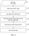
- This anatomy map can guide emission image reconstruction in adaptive regularization ( FIG. 2 ) and/or can use different kinetics models for different organs ( FIGS. 7A-8 ).
- a single medical imaging system includes an MR scanner, not encompassed by the wording of the claims but considered as useful for understanding the invention, or CT scanner for collecting anatomy images, and a PET scanner or SPECT scanner, the latter being not encompassed by the wording of the claims but considered as useful for understanding the invention, for collecting emission data representing radiotracer concentration.
- anatomy and activity data e.g., PET and CT data
- CT data for collecting anatomy images
- the anatomy data are segmented into organs.
- Each voxel is identified with a respective organ.
- the segmenting may be performed using machine learning, with a neural network trained with a set of organs from previous patients identified by trained inspectors.
- the neural network is trained to classify each voxel as belonging to a particular organ.
- the voxels can be assigned to organs using an image recognition algorithm (e.g., feature extraction) or a clustering algorithm.
- a respective identifier (e.g., integer number) is assigned to each voxel, corresponding to the organ to which that voxel belongs.
- the system builds a similarity map (according to equations (1) to (4), based on the anatomy (MR or CT) image for each voxel.
- the similarity map excludes voxels assigned to one or more organs to which the anatomy prior is not to be applied.
- the system determines whether the functional (PET or SPECT) image values are correlated with the anatomical (MR or CT) image values.
- the similarity map can be built using a radial Gaussian kernel.
- K(f j ,f k ) for each pair of anatomical pixels j and k is defined by equation (2).
- K f j f k exp ⁇ ⁇ f j ⁇ f k ⁇ 2 ⁇ 2
- f j and f k are anatomical feature vectors for pixels j and k, respectively
- K is a kernel function
- the parameter ⁇ controls the edge sensitivity.
- Equation (3) For expectation maximization (EM), the coefficient image is defined by equation (3).
- ⁇ n + 1 ⁇ n K T P T 1 AN K T P T y PK ⁇ n + A NR + S
- P ⁇ R M d ⁇ N v is the system matrix with p ij denoting the probability of detecting an event originating in voxel j in detector pair i
- r is a vector encompassing random and scattered events
- M d and N v represent the number of detector bins and voxels, respectively.
- A is attenuation correction factor
- N normalization factor
- S simulated scatter sinogram.
- the similarity matrix (map) K for a given organ is given by equation (4)
- K f j f k exp ⁇ ⁇ f j ⁇ f k ⁇ 2 ⁇ 2 organ f j
- the similarity map is applied in iterative image reconstruction, e.g., with the Ordered Subsets Expectation Maximization (OSEM) algorithm in equation (3).
- OSEM Ordered Subsets Expectation Maximization
- the system outputs the reconstructed images.
- the anatomy map of FIG. 1B and Table 1 can be used to specifically identify the organs that have good correlation between activity and the attenuation map in building the similarity matrix according to equation (4).
- the similarity values with adjacent voxels f k are calculated for voxels f j in organs that have good correlation between anatomy and activity, and no similarity values need to be calculated for voxels in organs that do not have good correlation between anatomy and activity.
- PET and CT data for the brain are known to have poor correlation, so there is no need to calculate similarity values for the voxels in the brain.
- This adaptive calculation of similarity matrix can be controlled by the factor organ(fj) in equation (4) since organ(fj) keeps track of which organ voxel f j belongs to.
- FIGS. 3A-3C show an example, which is not encompassed by the wording of the claims but is considered as useful for understanding the invention, where there is good correlation between (functional) PET image reconstruction with no anatomy prior (shown in FIG. 3A ) and the MR anatomy prior images of the brain ( FIG. 3B ). Both FIGS. 3A and 3B show details of the soft tissue of the brain. Consequently, reconstructing the PET image data of FIG. 3A using the anatomy prior information from the MR images in FIG. 3B provides a smoother image, as shown in FIG. 3C . Similarly, there is good correlation between the anatomy and emission information for the torso (not shown in FIGS. 3A-3C ), regardless of whether MR or CT data are used for the torso.
- FIGS. 4A-4C show an example where there is poor correlation between (activity) PET image reconstruction of the brain with no anatomy prior (shown in FIG. 4A ) and the CT anatomy prior images of the brain ( FIG. 4B).
- FIG. 4A shows details of the soft tissue of the brain, but the CT images in FIG. 4B only show the bone. Consequently, reconstructing the PET image data of FIG. 4A using the anatomy prior information from the CT images in FIG. 4B over-smooths the image, as shown in FIG. 4C , causing loss of detail while reducing noise.
- FIGS. 5A-5D a similarity matrix was built for all voxels that are located outside of the brain based on the attenuation map.
- the method distinguishes regions having different attenuation properties, assigning linear attenuation coefficients to them to provide an attenuation map to correct the PET emission data during reconstruction.
- the attenuation map prior can be successfully applied in the region outside of the brain.
- the reconstructed brain is not smoothed.
- FIG. 5A shows the result of standard uptake value (SUV) reconstruction without using any anatomy prior.
- the torso portions of the image are noisy.
- FIG. 5B shows the PET data from FIG. 5A , reconstructed using anatomy prior data from a corresponding CT image to the torso and the brain.
- the torso portion of the image is improved by noise reduction while retaining acceptable detail, but detail is lost in the brain portion of the image, since the brain anatomy (CT) data are not correlated with the brain activity (PET) data.
- CT brain anatomy
- PET brain activity
- FIG. 5C shows the image reconstructed using the similarity matrix for all voxels located outside the brain.
- the torso portion of the image benefits from noise reduction, similar to the torso in FIG. 5B , but the brain portion retains detail, similar to the brain portion of FIG. 5A .
- the benefit of retaining detail in the brain in FIG. 5C exceeds the cost of foregoing noise reduction in the brain.
- FIG. 5D shows the anatomy map overlaid with the CT data.
- the anatomy map from CT can be used to design more intelligent reconstruction algorithms by knowing to which organ each voxel belongs.
- the system can selectively and/or variably apply anatomy prior data for reconstruction of PET images, depending on the correlation between anatomy and activity data for each individual organ.
- the system can apply different regularization or anatomy prior to different organs.
- the system can apply different kinetics models to different organs for parametric imaging to increase accuracy and signal to noise ratio.
- FIGS. 6A-6D show another example using adaptive regularization strength with quadratic prior.
- MR magnetic resonance
- FIGS. 6A-6D show another example using adaptive regularization strength with quadratic prior.
- FIGS. 6A and 6B are coronal and sagittal views of a patient reconstructed with uniform regularization strength: 100% regularization strength for the torso (based on the CT data) and 100% regularization strength for the brain (based on the CT data). The brain portion of the image is over-smoothed.
- FIGS. 6C-6D show another method of reconstructing an image from the same PET data as FIGS. 6A and 6B using adaptive regularization strength.
- the regularization strength applied to the brain was one third of that applied to the rest of human body.
- FIGS. 6C and 6D By using a reduced regularization strength in FIGS. 6C and 6D , better resolution was preserved in the brain region (compared to FIGS. 6A and 6B ), while providing an acceptable noise level. This is only one example, and the regularization strength applied to any given organ can be varied to any value between 0% and 100%.
- the anatomy map can be applied to parametric imaging.
- Patlak model may be sufficient for tumor (hot spot) imaging.
- the parametric images Ki and Dv
- the linear Patlak model may be not accurate for parametric imaging for some organs.
- the system can apply different kinetics models to different organs. Applying different kinetic models to different organs may increase signal to noise ratio of parametric images.
- the anatomy map or segmentation table is used to determine to which organ each voxel is assigned, and each organ is assigned to a respective kinetics model.
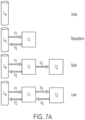
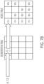
- FIGS. 7A and 7B schematically show an indexing method for determining which parameters are included in the kinetics model for a given organ. For example, as shown in FIG. 7B , if the segmentation table record corresponding to a given voxel contains the integer number 1, the model parameters for that voxel are identified in the first entry (e.g., row or column) of the model table. In this case, the first row of the model table indicates that a linear model is used, and the parameters K 1 and V 0 will be identified, and parametric K 1 and V 0 images will be reconstructed. Similarly, the remaining entries (rows or columns) of the model table identify the parameters of the models used for other organs.
- a Patlak model was applied to all of the voxels in the image.
- FIG. 7A shows four different schematic models for the aorta, myocardium, brain, and liver, respectively.
- the aorta is considered as a pass-through, with no tracer uptake, and no change in tracer concentration between the inlet to the aorta and exit from the aorta.
- the myocardium can be modeled as having one reversible compartment C1, with respective constants K 1 and K 2 defining tracer influx and outflux, respectively.
- the brain can be modeled as having a reversible compartment C 1 and an irreversible compartment C 2 .
- the parameter K 3 is added, denoting uptake by the irreversible compartment C 2 .
- the liver can be modeled as having two reversible compartments C 1 and C 2 .
- a liver outflux parameter K 4 is added.
- the anatomy map also allows organ-specific parametric imaging and can increase signal to noise ratio of parametric images.
- the anatomy map can be derived from high resolution CT images.
- CT anatomy
- PET emission
- the correlation information between anatomy (CT) and emission (PET) images allow more accurate kinetics modeling, to de-noise parametric images, and also to provide more desirable correction effects that adapt to clinical needs.
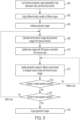
- Fig. 8 is a flow chart of a method applying different kinetics models to different organs in dynamic imaging.
- the emission data are collected.
- a single medical imaging system includes a CT scanner for collecting anatomy images, and a PET scanner for collecting emission data representing radiotracer concentration.
- the anatomy data are segmented into organs. Each voxel is identified with a respective organ. Any segmentation method can be used, such as those discussed above with respect to step 202 of FIG. 2 .
- a respective identifier (e.g., integer number) is assigned to each voxel, corresponding to the organ to which that voxel belongs.
- the system maps each identifier (e.g., integer number) to a respective kinetics model.
- the mapping can be as shown in FIG. 7A or FIG. 7B .
- the method loops through each organ to apply the respective kinetics model corresponding to each voxel.
- the system outputs parametric images for each of the model parameters.
- FIG. 9 shows an exemplary embodiment for applying different kinetic models to respective organs.
- the dynamic sinogram data, organ segmentation map, attenuation map, and the blood input function are input to the system.
- the sinogram data and organ segmentation map can be captured using a scanner having a PET acquisition scanner and a CT scanner.
- the sinogram data and organ segmentation map can be previously stored data accessed from a non-transitory, machine-readable storage medium.
- each organ is assigned to a respective kinetics model.
- the remaining steps in FIG. 10 are based on a linear Patlak model, but in other examples, one or more other models, such as multi-compartment models and/or non-linear models are used.
- each parametric image is initialized.
- all voxels for each parametric image can initially be set to a uniform value (e.g., all black, all white, or all gray.
- Steps 908 to 916 perform the main loop.
- the system calculates frame emission images using expectation maximization.
- the frame emission images include a respective SUV image for each time point at which the sinogram data are collected.
- the first time step 908 is performed, the frame emission images are calculated using the initial parameter values from step 904. Subsequently, each iteration of step 908 is performed using the parametric images from the previous iteration of the main loop.
- each frame image (SUV image corresponding to each collection time point during the scan) is updated based on the estimation from the previous time step. For example, the frame image corresponding to the second time point is updated based on the frame image corresponding to the first time point.
- Steps 912 and 914 form an inner loop to perform kinetic modeling.
- the inner loop updates the parametric images based on the frame images.
- Step 912 updates parametric images (e.g., the Ki an Dv images) for an organ based on its respective assigned kinetics model using the frame emission images. For each voxel, a line or curve (depending on the respective model assigned to each organ) is fit to the frame image data for that voxel over all of the time points, and the parameter values (e.g., Ki and Dv) are determined.
- parametric images e.g., the Ki an Dv images
- step 914 the updates to the parametric images in step 912 are repeated for each organ.
- step 916 the main loop from step 908 to 916 is repeated until a desired number of iterations have been performed.
- step 918 once the desired number of iterations are performed, the respective parametric images for each organ are output.
- FIG. 10 shows an exemplary embodiment for applying different kinetic models to respective organs, where the organs include at least the aorta.
- the dynamic sinogram data, organ segmentation map, attenuation map, and the blood input function are input to the system.
- the scanner is operated in continuous bed motion (CBM) mode.
- CBM continuous bed motion
- step-and-scan mode is used.
- the sinogram data and organ segmentation map can be captured using a scanner having a PET acquisition scanner and a CT scanner.
- the sinogram data and organ segmentation map can be previously stored data accessed from a non-transitory, machine-readable storage medium.
- the system calculates the blood tracer concentration C B (t) and the integral of C B (t) for each time point, for each axial slice of the scan.
- the method to calculate image slice reference time of different scan passes for parametric PET are based on finely sampled "bed tags".
- Bed tags are coordinate pairs accurately encoding position and time information of the bed throughout the scan. In a system scanning in CBM mode, bed tags can be recorded periodically, providing an accurate record of position versus time regardless of bed speed and acceleration. In other embodiments, the system scans in step-and-shoot mode.
- each parametric image (e.g., Ki and DV) is initialized.
- all voxels for each parametric image can initially be set to a uniform value (e.g., all black, all white, or all gray.
- Steps 1005 to 1016 perform the main loop.
- Steps 1005 and 1007 constitute a regularization step.
- the system calculates the mean parameter values for each parameter (e.g., Ki, DV) for the voxels in each organ.
- the mean parameter values are assigned for the aorta.
- Ki and DV are calculated for each voxel using equations (6) and (7), respectively:
- each voxel is set to the mean parameter values Ki and DV computed in step 1005.
- the system calculates frame emission images using (the Patlak) equation (8).
- x j t K i j DV j K i j ⁇ o t C p ⁇ d ⁇ + DV j C p t
- the frame emission images include a respective SUV image for each time point at which the sinogram data are collected.
- the first time step 1008 is performed, the frame emission images are calculated using the initial parametric images from step 1004. Subsequently, each iteration of step 1008 is performed using the parametric images from the previous iteration of the main loop (steps 1005-1016).
- each frame image (SUV images corresponding to each collection time point during the scan) is updated based on the estimation from step 1008.
- Steps 1012 and 1014 form an inner loop to perform kinetic modeling.
- Step 1012 updates parametric images (e.g., the Ki an Dv images) for an organ based on its respective assigned kinetics model using the frame emission images. For each voxel, a line or curve is fit to the frame image data for that voxel over all of the time points, and the parameter values (e.g., Ki and Dv) are determined.
- parametric images e.g., the Ki an Dv images
- step 1014 the updates to the parametric images in step 1012 are repeated for each organ.
- step 1016 the main loop from step 1008 to 1016 is repeated until a desired number of iterations have been performed.
- the processor outputs Ki and DV parametric images.
- FIGS. 11A-11E compare parametric images of the same subject before and after application of the aorta anatomy map.
- FIG. 11A shows a sagittal view CT image of the subject.
- the aorta is labeled and is readily distinguished from surrounding organs.
- the CT image of FIG. 11A has low noise.
- FIG. 11B shows the sagittal view Ki parametric image of the same subject, without applying the aorta map information of FIG. 11A .
- the aorta is labeled in FIG. 11B , but the image contains a large amount of noise.
- FIG. 11C shows the sagittal view Ki parametric image of the same subject, after applying the aorta map information of FIG. 11A .
- the aorta is labeled in FIG. 11C .
- Noise is substantially reduced relative to FIG. 11B , and the image quality of the aorta is improved.
- FIG. 11D shows the sagittal view DV parametric image of the same subject, without applying the aorta map information of FIG. 11A .
- the aorta is labeled in FIG. 11D .
- the image contains a large amount of noise.
- FIG. 11E shows the sagittal view DV parametric image of the same subject, after applying the aorta map information of FIG. 11A .
- the aorta is labeled in FIG. 11E .
- Noise is substantially reduced, and the image quality of the aorta is improved.
- FIGS. 12A-12D show a similar improvement in parametric images of the liver obtained by applying the liver map to PET parametric image processing.
- FIG. 12A shows the anterior view Ki parametric image of the subject, without applying the liver map.
- the liver is labeled in FIG. 12A , but the image contains a large amount of noise.
- FIG. 12B shows the sagittal view Ki parametric image of the same subject, after applying the liver map information.
- the liver is labeled in FIG. 12B .
- Noise is substantially reduced relative to FIG. 12A , and the image quality of the liver is improved.
- FIG. 12C shows the anterior view DV parametric image of the subject, without applying the liver map.
- the liver is labeled in FIG. 12C , but the image contains a large amount of noise.
- FIG. 12D shows the sagittal view DV parametric image of the same subject, after applying the liver map information.
- the liver is labeled in FIG. 12D .
- Noise is substantially reduced relative to FIG. 12C , and the image quality of the liver is improved.
- the signal to noise ratio in the aorta or liver region of parametric images can be improved by including the anatomy information of the aorta or liver (or other organ of interest) in the nested Patlak image reconstruction.
- the techniques described above can be applied to parametric imaging of other organs.
- the anatomy map can also be used in other data correction methods, such as motion correction, scatter correction, and point spread function.
- the anatomy map can also be used for the following aspects, either alone, or in any combination:
- the methods and system described herein may be at least partially embodied in the form of computer-implemented processes and apparatus for practicing those processes.
- the disclosed methods may also be at least partially embodied in the form of tangible, non-transitory machine readable storage media encoded with computer program code.
- the media may include, for example, RAMs, ROMs, CD-ROMs, DVD-ROMs, BD-ROMs, hard disk drives, flash memories, or any other non-transitory machine-readable storage medium, wherein, when the computer program code is loaded into and executed by a computer, the computer becomes an apparatus for practicing the method.
- the methods may also be at least partially embodied in the form of a computer into which computer program code is loaded and/or executed, such that, the computer becomes a special purpose computer for practicing the methods.
- the computer program code segments configure the processor to create specific logic circuits.
- the methods may alternatively be at least partially embodied in a digital signal processor formed of application specific integrated circuits for performing the methods.
Landscapes
- Engineering & Computer Science (AREA)
- Health & Medical Sciences (AREA)
- Theoretical Computer Science (AREA)
- Physics & Mathematics (AREA)
- General Physics & Mathematics (AREA)
- Medical Informatics (AREA)
- Life Sciences & Earth Sciences (AREA)
- General Health & Medical Sciences (AREA)
- Radiology & Medical Imaging (AREA)
- Nuclear Medicine, Radiotherapy & Molecular Imaging (AREA)
- Computer Vision & Pattern Recognition (AREA)
- Surgery (AREA)
- Biophysics (AREA)
- Biomedical Technology (AREA)
- Heart & Thoracic Surgery (AREA)
- Molecular Biology (AREA)
- High Energy & Nuclear Physics (AREA)
- Animal Behavior & Ethology (AREA)
- Pathology (AREA)
- Public Health (AREA)
- Veterinary Medicine (AREA)
- Optics & Photonics (AREA)
- Pulmonology (AREA)
- Quality & Reliability (AREA)
- Apparatus For Radiation Diagnosis (AREA)
- Nuclear Medicine (AREA)
- Magnetic Resonance Imaging Apparatus (AREA)
Claims (10)
- Verfahren zum Rekonstruieren von medizinischen Bildern, umfassend:Identifizieren mehrerer Organe in einem Körper eines Subjekts basierend auf einem anatomischen Bild;Zuweisen mehrerer Voxel in dem Körper zu jeweiligen Organen der mehreren Organe basierend auf dem anatomischen Bild; undRekonstruieren eines Aktivitätsbildes des Körpers, wobei jeweils eine unterschiedliche Verarbeitung für die Voxel verwendet wird, die jedem jeweiligen Organ der mehreren Organe zugewiesen sind,wobei das Rekonstruieren das Durchführen einer Regularisierung für ein oder mehrere ausgewählte Organe basierend auf Informationen aus dem anatomischen Bild beinhaltet;wobei die ausgewählten Organe basierend auf einer Korrelation zwischen Voxelwerten des anatomischen Bildes und Voxelwerten des Aktivitätsbildes ausgewählt sind;und wobei das anatomische Bild ein CT-Bild ist, das Aktivitätsbild ein PET-Bild ist und das Rekonstruieren beinhaltet:Verwenden der Informationen aus dem anatomischen Bild, um einen Abschnitt des Aktivitätsbildes zu rekonstruieren, der ein Organ in einem Torso des Körpers enthält; undRekonstruieren eines Abschnitts des Aktivitätsbildes, der ein Gehirn enthält, ohne Informationen aus dem anatomischen Bild.
- Verfahren nach Anspruch 1, wobei die Regularisierung adaptiv durchgeführt wird, basierend auf dem Organ, dem jedes Voxel zugewiesen ist.
- Verfahren nach Anspruch 1, ferner umfassend das Anwenden jeweils unterschiedlicher kinetischer Modelle auf Voxel, die jeweils unterschiedlichen Organen der mehreren Organe zugewiesen sind.
- Verfahren nach Anspruch 1, ferner umfassend das Anwenden jeweils unterschiedlicher Bildkorrekturen auf Voxel, die jeweils unterschiedlichen Organen der mehreren Organe zugewiesen sind.
- Verfahren nach Anspruch 4, wobei die jeweils unterschiedlichen Bildkorrekturen jeweils unterschiedliche Punktspreizfunktionen, eine jeweils unterschiedliche Streuungsskalierung oder eine jeweils unterschiedliche Bewegungskorrektur beinhalten.
- System zum Rekonstruieren von medizinischen Bildern, umfassend:ein nicht-transitorisches, maschinenlesbares Datenspeichermedium, das gekoppelt ist, um medizinische Bilddaten zu empfangen, wobei das maschinenlesbare Datenspeichermedium Anweisungen enthält; undeinen Prozessor, der an das maschinenlesbare Datenspeichermedium gekoppelt ist, um Anweisungen auszuführen, wobei die Anweisungen den Prozessor für das Durchführen eines Verfahrens konfigurieren, welches umfasst:Identifizieren mehrerer Organe in einem Körper eines Subjekts basierend auf einem anatomischen Bild;Zuweisen mehrerer Voxel in dem Körper zu jeweiligen Organen der mehreren Organe basierend auf dem anatomischen Bild; undRekonstruieren eines Aktivitätsbildes des Körpers, wobei jeweils eine unterschiedliche Verarbeitung für die Voxel verwendet wird, die jedem jeweiligen Organ der mehreren Organe zugewiesen sind; wobeidas Rekonstruieren das Durchführen einer Regularisierung für ein oder mehrere ausgewählte Organe basierend auf Informationen aus dem anatomischen Bild beinhaltet; und wobeidie ausgewählten Organe basierend auf einer Korrelation zwischen Voxelwerten des anatomischen Bildes und Voxelwerten des Aktivitätsbildes ausgewählt sind, wobei das anatomische Bild ein CT-Bild ist, das Aktivitätsbild ein PET-Bild ist und das Rekonstruieren beinhaltet:Verwenden der Informationen aus dem anatomischen Bild, um einen Abschnitt des Aktivitätsbildes zu rekonstruieren, der ein Organ in einem Torso des Körpers enthält; undRekonstruieren eines Abschnitts des Aktivitätsbildes, der ein Gehirn enthält, ohne Informationen aus dem anatomischen Bild.
- System nach Anspruch 6, wobei die Regularisierung adaptiv durchgeführt wird, basierend auf dem Organ, dem jedes Voxel zugewiesen ist.
- System nach Anspruch 6, ferner umfassend das Anwenden jeweils unterschiedlicher kinetischer Modelle auf Voxel, die jeweils unterschiedlichen Organen der mehreren Organe zugewiesen sind.
- Nicht-transitorisches, maschinenlesbares Datenspeichermedium, das Anweisungen enthält, sodass, wenn ein Prozessor die Anweisungen ausführt, die Anweisungen den Prozessor hierdurch für das Rekonstruieren von medizinischen Bildern konfiguriert:Identifizieren mehrerer Organe in einem Körper eines Subjekts basierend auf einem anatomischen Bild;Zuweisen mehrerer Voxel in dem Körper zu jeweiligen Organen der mehreren Organe basierend auf dem anatomischen Bild; undRekonstruieren eines Aktivitätsbildes des Körpers, wobei jeweils eine unterschiedliche Verarbeitung für die Voxel verwendet wird, die jedem jeweiligen Organ der mehreren Organe zugewiesen sind, wobeidas Rekonstruieren das Durchführen einer Regularisierung für ein oder mehrere ausgewählte Organe basierend auf Informationen aus dem anatomischen Bild beinhaltet; und wobeidie ausgewählten Organe basierend auf einer Korrelation zwischen Voxelwerten des anatomischen Bildes und Voxelwerten des Aktivitätsbildes ausgewählt sind, wobei das anatomische Bild ein CT-Bild ist, das Aktivitätsbild ein PET-Bild ist und das Rekonstruieren beinhaltet:Verwenden der Informationen aus dem anatomischen Bild, um einen Abschnitt des Aktivitätsbildes zu rekonstruieren, der ein Organ in einem Torso des Körpers enthält; undRekonstruieren eines Abschnitts des Aktivitätsbildes, der ein Gehirn enthält, ohne Informationen aus dem anatomischen Bild.
- Nicht-transitorisches, maschinenlesbare Datenspeichermedium nach Anspruch 9, ferner umfassend Anweisungen zum Anwenden jeweils unterschiedlicher kinetischer Modelle auf Voxel, die jeweils unterschiedlichen Organen der mehreren Organe zugewiesen sind.
Priority Applications (1)
| Application Number | Priority Date | Filing Date | Title |
|---|---|---|---|
| EP24181637.0A EP4407561A3 (de) | 2018-10-23 | 2019-07-18 | Aktivitätsbildrekonstruktion unter verwendung von anatomiedaten |
Applications Claiming Priority (2)
| Application Number | Priority Date | Filing Date | Title |
|---|---|---|---|
| US16/167,819 US10762626B2 (en) | 2018-10-23 | 2018-10-23 | Activity image reconstruction using anatomy data |
| PCT/US2019/042312 WO2020086128A1 (en) | 2018-10-23 | 2019-07-18 | Activity image reconstruction using anatomy data |
Related Child Applications (2)
| Application Number | Title | Priority Date | Filing Date |
|---|---|---|---|
| EP24181637.0A Division EP4407561A3 (de) | 2018-10-23 | 2019-07-18 | Aktivitätsbildrekonstruktion unter verwendung von anatomiedaten |
| EP24181637.0A Division-Into EP4407561A3 (de) | 2018-10-23 | 2019-07-18 | Aktivitätsbildrekonstruktion unter verwendung von anatomiedaten |
Publications (3)
| Publication Number | Publication Date |
|---|---|
| EP3853818A1 EP3853818A1 (de) | 2021-07-28 |
| EP3853818C0 EP3853818C0 (de) | 2024-07-17 |
| EP3853818B1 true EP3853818B1 (de) | 2024-07-17 |
Family
ID=67515149
Family Applications (2)
| Application Number | Title | Priority Date | Filing Date |
|---|---|---|---|
| EP24181637.0A Pending EP4407561A3 (de) | 2018-10-23 | 2019-07-18 | Aktivitätsbildrekonstruktion unter verwendung von anatomiedaten |
| EP19749076.6A Active EP3853818B1 (de) | 2018-10-23 | 2019-07-18 | Rekonstruktion eines aktivitätsbildes unter verwendung von anatomiedaten |
Family Applications Before (1)
| Application Number | Title | Priority Date | Filing Date |
|---|---|---|---|
| EP24181637.0A Pending EP4407561A3 (de) | 2018-10-23 | 2019-07-18 | Aktivitätsbildrekonstruktion unter verwendung von anatomiedaten |
Country Status (6)
| Country | Link |
|---|---|
| US (1) | US10762626B2 (de) |
| EP (2) | EP4407561A3 (de) |
| JP (1) | JP7312820B2 (de) |
| CN (1) | CN112912934B (de) |
| CA (1) | CA3117317C (de) |
| WO (1) | WO2020086128A1 (de) |
Families Citing this family (7)
| Publication number | Priority date | Publication date | Assignee | Title |
|---|---|---|---|---|
| US11100611B2 (en) * | 2019-03-29 | 2021-08-24 | GE Precision Healthcare LLC | Systems and methods for background noise reduction in magnetic resonance images |
| CN113537279B (zh) * | 2021-05-18 | 2024-07-02 | 齐鲁工业大学 | 基于类残差卷积和lstm的covid-19识别系统 |
| CN113781594A (zh) * | 2021-08-17 | 2021-12-10 | 杭州微影医疗科技有限公司 | 一种基于解剖先验数据的磁共振成像图像重建方法 |
| EP4704705A1 (de) * | 2023-06-09 | 2026-03-11 | Siemens Medical Solutions USA, Inc. | Dämpfungskorrektur für medizinische bildgebung |
| US12530828B2 (en) * | 2023-11-20 | 2026-01-20 | Siemens Medical Solutions Usa, Inc. | Parametric imaging without pre-scan blood input function |
| US20250252619A1 (en) * | 2024-02-06 | 2025-08-07 | Siemens Medical Solutions Usa, Inc. | Dose-less organ segmentation based on nuclear image |
| CN120609788B (zh) * | 2025-06-12 | 2025-12-05 | 四川省环境工程评估中心 | 基于超分辨率混合gan的遥感水质污染检测方法 |
Family Cites Families (15)
| Publication number | Priority date | Publication date | Assignee | Title |
|---|---|---|---|---|
| US7534418B2 (en) * | 2004-12-10 | 2009-05-19 | The Regents Of The University Of Michigan | Imaging agents |
| JP5269283B2 (ja) | 2005-04-06 | 2013-08-21 | 株式会社東芝 | 医用画像診断装置及び画像再構成方法 |
| FR2886433B1 (fr) * | 2005-05-30 | 2007-09-07 | Commissariat Energie Atomique | Methode de segmentation d'une sequence d'images tridimensionnelles, notamment en pharmaco-imagerie. |
| WO2010018478A1 (en) * | 2008-08-15 | 2010-02-18 | Koninklijke Philips Electronics, N.V. | Attenuation correction for pet or spect nuclear imaging systems using magnetic resonance spectroscopic image data |
| RU2013136488A (ru) | 2011-01-05 | 2015-02-10 | Конинклейке Филипс Электроникс Н.В. | Способ и устройство детектирования и коррекции движения в данных позитронно-эмиссионной томографии в режиме списка с использованием синхронизированного сигнала |
| JP5706389B2 (ja) | 2011-12-20 | 2015-04-22 | 富士フイルム株式会社 | 画像処理装置および画像処理方法、並びに、画像処理プログラム |
| US9364192B2 (en) * | 2013-03-15 | 2016-06-14 | Siemens Medical Solutions Usa, Inc. | Error estimates in quantitative functional imaging |
| JP6123652B2 (ja) | 2013-11-27 | 2017-05-10 | 株式会社島津製作所 | 散乱成分推定方法 |
| JP6425885B2 (ja) | 2013-12-20 | 2018-11-21 | キヤノンメディカルシステムズ株式会社 | 核医学診断装置、画像処理装置および画像処理プログラム |
| JP6815167B2 (ja) | 2015-11-02 | 2021-01-20 | キヤノンメディカルシステムズ株式会社 | 医用画像診断システム、形態画像診断装置及び核医学画像診断装置 |
| US10210634B2 (en) * | 2016-07-20 | 2019-02-19 | Shanghai United Imaging Healthcare Co., Ltd. | System and method for segmenting medical image |
| JP7159167B2 (ja) * | 2017-01-06 | 2022-10-24 | コーニンクレッカ フィリップス エヌ ヴェ | 陽電子放出断層撮影(pet)撮像における結果のロバスト性を向上させるための標準取込値(suv)誘導再構成制御 |
| US10366491B2 (en) | 2017-03-08 | 2019-07-30 | Siemens Healthcare Gmbh | Deep image-to-image recurrent network with shape basis for automatic vertebra labeling in large-scale 3D CT volumes |
| US10600185B2 (en) | 2017-03-08 | 2020-03-24 | Siemens Healthcare Gmbh | Automatic liver segmentation using adversarial image-to-image network |
| EP3301649B1 (de) * | 2017-09-07 | 2019-10-30 | Siemens Healthcare GmbH | Verfahren zur verarbeitung daten medizinischer bilder und bildverarbeitungssystem für daten medizinischer bilder |
-
2018
- 2018-10-23 US US16/167,819 patent/US10762626B2/en active Active
-
2019
- 2019-07-18 CA CA3117317A patent/CA3117317C/en active Active
- 2019-07-18 EP EP24181637.0A patent/EP4407561A3/de active Pending
- 2019-07-18 JP JP2021521489A patent/JP7312820B2/ja active Active
- 2019-07-18 WO PCT/US2019/042312 patent/WO2020086128A1/en not_active Ceased
- 2019-07-18 CN CN201980070197.7A patent/CN112912934B/zh active Active
- 2019-07-18 EP EP19749076.6A patent/EP3853818B1/de active Active
Also Published As
| Publication number | Publication date |
|---|---|
| CA3117317A1 (en) | 2020-04-30 |
| CN112912934A (zh) | 2021-06-04 |
| EP4407561A3 (de) | 2024-10-09 |
| WO2020086128A1 (en) | 2020-04-30 |
| EP3853818C0 (de) | 2024-07-17 |
| CA3117317C (en) | 2022-04-19 |
| US10762626B2 (en) | 2020-09-01 |
| JP2022505451A (ja) | 2022-01-14 |
| US20200126214A1 (en) | 2020-04-23 |
| EP4407561A2 (de) | 2024-07-31 |
| CN112912934B (zh) | 2023-01-24 |
| JP7312820B2 (ja) | 2023-07-21 |
| EP3853818A1 (de) | 2021-07-28 |
Similar Documents
| Publication | Publication Date | Title |
|---|---|---|
| EP3853818B1 (de) | Rekonstruktion eines aktivitätsbildes unter verwendung von anatomiedaten | |
| JP7515502B2 (ja) | 陽電子放射断層撮影を用いた腫瘍セグメンテーションのための深層畳み込みニューラルネットワーク | |
| CN111008984B (zh) | 医学影像中正常器官的轮廓线自动勾画方法 | |
| US8675936B2 (en) | Multimodal image reconstruction | |
| US20190343477A1 (en) | Methods and systems for extracting blood vessel | |
| CN104135931B (zh) | 用于减少成像数据中的局部伪影的方法和系统 | |
| US8218848B2 (en) | System and method for the generation of attenuation correction maps from MR images | |
| EP3796842B1 (de) | Patientenadaptive nuklearmedizinische bildgebung | |
| CN108885786B (zh) | 医学图像处理 | |
| CN114494479A (zh) | 利用神经网络对低剂量pet图像进行同时衰减校正、散射校正和去噪声的系统和方法 | |
| Li et al. | Multienergy cone-beam computed tomography reconstruction with a spatial spectral nonlocal means algorithm | |
| Chan et al. | Median non-local means filtering for low SNR image denoising: Application to PET with anatomical knowledge | |
| CN112365593B (zh) | 一种pet图像重建的方法和系统 | |
| EP4446994A1 (de) | Systeme und verfahren zur automatischen qualitätskontrolle einer bildrekonstruktion | |
| CN116977552A (zh) | 一种立体视觉引导的pet图像重建方法、系统、设备 | |
| Boudjelal et al. | PET image reconstruction based on Bayesian inference regularised maximum likelihood expectation maximisation (MLEM) method | |
| CN105719256A (zh) | 一种基于结构图像引导的pet图像部分容积校正方法 | |
| CN108010093A (zh) | 一种pet图像重建方法和装置 | |
| JP7487406B2 (ja) | 鮮鋭性保持呼吸動き補償 | |
| Ashouri et al. | Kernel-based reconstruction of C-11-hydroxyephedrine cardiac PET images of the sympathetic nervous system | |
| US20260080597A1 (en) | Morphing functional image data to match associated anatomical image data | |
| Bruyant et al. | Human and numerical observer studies of lesion detection in Ga-67 images obtained with MAP-EM reconstructions and anatomical priors |
Legal Events
| Date | Code | Title | Description |
|---|---|---|---|
| STAA | Information on the status of an ep patent application or granted ep patent |
Free format text: STATUS: UNKNOWN |
|
| STAA | Information on the status of an ep patent application or granted ep patent |
Free format text: STATUS: THE INTERNATIONAL PUBLICATION HAS BEEN MADE |
|
| PUAI | Public reference made under article 153(3) epc to a published international application that has entered the european phase |
Free format text: ORIGINAL CODE: 0009012 |
|
| STAA | Information on the status of an ep patent application or granted ep patent |
Free format text: STATUS: REQUEST FOR EXAMINATION WAS MADE |
|
| 17P | Request for examination filed |
Effective date: 20210422 |
|
| AK | Designated contracting states |
Kind code of ref document: A1 Designated state(s): AL AT BE BG CH CY CZ DE DK EE ES FI FR GB GR HR HU IE IS IT LI LT LU LV MC MK MT NL NO PL PT RO RS SE SI SK SM TR |
|
| STAA | Information on the status of an ep patent application or granted ep patent |
Free format text: STATUS: EXAMINATION IS IN PROGRESS |
|
| DAV | Request for validation of the european patent (deleted) | ||
| DAX | Request for extension of the european patent (deleted) | ||
| 17Q | First examination report despatched |
Effective date: 20220125 |
|
| GRAP | Despatch of communication of intention to grant a patent |
Free format text: ORIGINAL CODE: EPIDOSNIGR1 |
|
| STAA | Information on the status of an ep patent application or granted ep patent |
Free format text: STATUS: GRANT OF PATENT IS INTENDED |
|
| INTG | Intention to grant announced |
Effective date: 20240209 |
|
| GRAS | Grant fee paid |
Free format text: ORIGINAL CODE: EPIDOSNIGR3 |
|
| GRAA | (expected) grant |
Free format text: ORIGINAL CODE: 0009210 |
|
| STAA | Information on the status of an ep patent application or granted ep patent |
Free format text: STATUS: THE PATENT HAS BEEN GRANTED |
|
| AK | Designated contracting states |
Kind code of ref document: B1 Designated state(s): AL AT BE BG CH CY CZ DE DK EE ES FI FR GB GR HR HU IE IS IT LI LT LU LV MC MK MT NL NO PL PT RO RS SE SI SK SM TR |
|
| REG | Reference to a national code |
Ref country code: CH Ref legal event code: EP |
|
| REG | Reference to a national code |
Ref country code: DE Ref legal event code: R096 Ref document number: 602019055367 Country of ref document: DE |
|
| REG | Reference to a national code |
Ref country code: IE Ref legal event code: FG4D |
|
| U01 | Request for unitary effect filed |
Effective date: 20240730 |
|
| U07 | Unitary effect registered |
Designated state(s): AT BE BG DE DK EE FI FR IT LT LU LV MT NL PT RO SE SI Effective date: 20240902 |
|
| U20 | Renewal fee for the european patent with unitary effect paid |
Year of fee payment: 6 Effective date: 20240902 |
|
| PG25 | Lapsed in a contracting state [announced via postgrant information from national office to epo] |
Ref country code: NO Free format text: LAPSE BECAUSE OF FAILURE TO SUBMIT A TRANSLATION OF THE DESCRIPTION OR TO PAY THE FEE WITHIN THE PRESCRIBED TIME-LIMIT Effective date: 20241017 |
|
| PG25 | Lapsed in a contracting state [announced via postgrant information from national office to epo] |
Ref country code: GR Free format text: LAPSE BECAUSE OF FAILURE TO SUBMIT A TRANSLATION OF THE DESCRIPTION OR TO PAY THE FEE WITHIN THE PRESCRIBED TIME-LIMIT Effective date: 20241018 Ref country code: PL Free format text: LAPSE BECAUSE OF FAILURE TO SUBMIT A TRANSLATION OF THE DESCRIPTION OR TO PAY THE FEE WITHIN THE PRESCRIBED TIME-LIMIT Effective date: 20240717 |
|
| PG25 | Lapsed in a contracting state [announced via postgrant information from national office to epo] |
Ref country code: IS Free format text: LAPSE BECAUSE OF FAILURE TO SUBMIT A TRANSLATION OF THE DESCRIPTION OR TO PAY THE FEE WITHIN THE PRESCRIBED TIME-LIMIT Effective date: 20241117 |
|
| PG25 | Lapsed in a contracting state [announced via postgrant information from national office to epo] |
Ref country code: HR Free format text: LAPSE BECAUSE OF FAILURE TO SUBMIT A TRANSLATION OF THE DESCRIPTION OR TO PAY THE FEE WITHIN THE PRESCRIBED TIME-LIMIT Effective date: 20240717 |
|
| PG25 | Lapsed in a contracting state [announced via postgrant information from national office to epo] |
Ref country code: ES Free format text: LAPSE BECAUSE OF FAILURE TO SUBMIT A TRANSLATION OF THE DESCRIPTION OR TO PAY THE FEE WITHIN THE PRESCRIBED TIME-LIMIT Effective date: 20240717 Ref country code: RS Free format text: LAPSE BECAUSE OF FAILURE TO SUBMIT A TRANSLATION OF THE DESCRIPTION OR TO PAY THE FEE WITHIN THE PRESCRIBED TIME-LIMIT Effective date: 20241017 |
|
| PG25 | Lapsed in a contracting state [announced via postgrant information from national office to epo] |
Ref country code: RS Free format text: LAPSE BECAUSE OF FAILURE TO SUBMIT A TRANSLATION OF THE DESCRIPTION OR TO PAY THE FEE WITHIN THE PRESCRIBED TIME-LIMIT Effective date: 20241017 Ref country code: PL Free format text: LAPSE BECAUSE OF FAILURE TO SUBMIT A TRANSLATION OF THE DESCRIPTION OR TO PAY THE FEE WITHIN THE PRESCRIBED TIME-LIMIT Effective date: 20240717 Ref country code: NO Free format text: LAPSE BECAUSE OF FAILURE TO SUBMIT A TRANSLATION OF THE DESCRIPTION OR TO PAY THE FEE WITHIN THE PRESCRIBED TIME-LIMIT Effective date: 20241017 Ref country code: IS Free format text: LAPSE BECAUSE OF FAILURE TO SUBMIT A TRANSLATION OF THE DESCRIPTION OR TO PAY THE FEE WITHIN THE PRESCRIBED TIME-LIMIT Effective date: 20241117 Ref country code: HR Free format text: LAPSE BECAUSE OF FAILURE TO SUBMIT A TRANSLATION OF THE DESCRIPTION OR TO PAY THE FEE WITHIN THE PRESCRIBED TIME-LIMIT Effective date: 20240717 Ref country code: GR Free format text: LAPSE BECAUSE OF FAILURE TO SUBMIT A TRANSLATION OF THE DESCRIPTION OR TO PAY THE FEE WITHIN THE PRESCRIBED TIME-LIMIT Effective date: 20241018 Ref country code: ES Free format text: LAPSE BECAUSE OF FAILURE TO SUBMIT A TRANSLATION OF THE DESCRIPTION OR TO PAY THE FEE WITHIN THE PRESCRIBED TIME-LIMIT Effective date: 20240717 |
|
| REG | Reference to a national code |
Ref country code: CH Ref legal event code: PL |
|
| PG25 | Lapsed in a contracting state [announced via postgrant information from national office to epo] |
Ref country code: SM Free format text: LAPSE BECAUSE OF FAILURE TO SUBMIT A TRANSLATION OF THE DESCRIPTION OR TO PAY THE FEE WITHIN THE PRESCRIBED TIME-LIMIT Effective date: 20240717 |
|
| PG25 | Lapsed in a contracting state [announced via postgrant information from national office to epo] |
Ref country code: CH Free format text: LAPSE BECAUSE OF NON-PAYMENT OF DUE FEES Effective date: 20240731 Ref country code: MC Free format text: LAPSE BECAUSE OF FAILURE TO SUBMIT A TRANSLATION OF THE DESCRIPTION OR TO PAY THE FEE WITHIN THE PRESCRIBED TIME-LIMIT Effective date: 20240717 |
|
| PG25 | Lapsed in a contracting state [announced via postgrant information from national office to epo] |
Ref country code: CZ Free format text: LAPSE BECAUSE OF FAILURE TO SUBMIT A TRANSLATION OF THE DESCRIPTION OR TO PAY THE FEE WITHIN THE PRESCRIBED TIME-LIMIT Effective date: 20240717 |
|
| PG25 | Lapsed in a contracting state [announced via postgrant information from national office to epo] |
Ref country code: SK Free format text: LAPSE BECAUSE OF FAILURE TO SUBMIT A TRANSLATION OF THE DESCRIPTION OR TO PAY THE FEE WITHIN THE PRESCRIBED TIME-LIMIT Effective date: 20240717 |
|
| PLBE | No opposition filed within time limit |
Free format text: ORIGINAL CODE: 0009261 |
|
| STAA | Information on the status of an ep patent application or granted ep patent |
Free format text: STATUS: NO OPPOSITION FILED WITHIN TIME LIMIT |
|
| 26N | No opposition filed |
Effective date: 20250422 |
|
| PG25 | Lapsed in a contracting state [announced via postgrant information from national office to epo] |
Ref country code: IE Free format text: LAPSE BECAUSE OF NON-PAYMENT OF DUE FEES Effective date: 20240718 |
|
| U20 | Renewal fee for the european patent with unitary effect paid |
Year of fee payment: 7 Effective date: 20250718 |
|
| PGFP | Annual fee paid to national office [announced via postgrant information from national office to epo] |
Ref country code: GB Payment date: 20250811 Year of fee payment: 7 |
|
| PG25 | Lapsed in a contracting state [announced via postgrant information from national office to epo] |
Ref country code: CY Free format text: LAPSE BECAUSE OF FAILURE TO SUBMIT A TRANSLATION OF THE DESCRIPTION OR TO PAY THE FEE WITHIN THE PRESCRIBED TIME-LIMIT; INVALID AB INITIO Effective date: 20190718 |
|
| PG25 | Lapsed in a contracting state [announced via postgrant information from national office to epo] |
Ref country code: HU Free format text: LAPSE BECAUSE OF FAILURE TO SUBMIT A TRANSLATION OF THE DESCRIPTION OR TO PAY THE FEE WITHIN THE PRESCRIBED TIME-LIMIT; INVALID AB INITIO Effective date: 20190718 |