EP3853864B1 - Entrée sécurisée sur un composant de commande d'un dispositif de dialyse - Google Patents
Entrée sécurisée sur un composant de commande d'un dispositif de dialyse Download PDFInfo
- Publication number
- EP3853864B1 EP3853864B1 EP19769129.8A EP19769129A EP3853864B1 EP 3853864 B1 EP3853864 B1 EP 3853864B1 EP 19769129 A EP19769129 A EP 19769129A EP 3853864 B1 EP3853864 B1 EP 3853864B1
- Authority
- EP
- European Patent Office
- Prior art keywords
- control
- medical device
- control component
- operating element
- detected
- Prior art date
- Legal status (The legal status is an assumption and is not a legal conclusion. Google has not performed a legal analysis and makes no representation as to the accuracy of the status listed.)
- Active
Links
Images

Classifications
-
- A—HUMAN NECESSITIES
- A61—MEDICAL OR VETERINARY SCIENCE; HYGIENE
- A61M—DEVICES FOR INTRODUCING MEDIA INTO, OR ONTO, THE BODY; DEVICES FOR TRANSDUCING BODY MEDIA OR FOR TAKING MEDIA FROM THE BODY; DEVICES FOR PRODUCING OR ENDING SLEEP OR STUPOR
- A61M1/00—Suction or pumping devices for medical purposes; Devices for carrying-off, for treatment of, or for carrying-over, body-liquids; Drainage systems
- A61M1/14—Dialysis systems; Artificial kidneys; Blood oxygenators ; Reciprocating systems for treatment of body fluids, e.g. single needle systems for hemofiltration or pheresis
- A61M1/16—Dialysis systems; Artificial kidneys; Blood oxygenators ; Reciprocating systems for treatment of body fluids, e.g. single needle systems for hemofiltration or pheresis with membranes
- A61M1/1601—Control or regulation
-
- A—HUMAN NECESSITIES
- A61—MEDICAL OR VETERINARY SCIENCE; HYGIENE
- A61M—DEVICES FOR INTRODUCING MEDIA INTO, OR ONTO, THE BODY; DEVICES FOR TRANSDUCING BODY MEDIA OR FOR TAKING MEDIA FROM THE BODY; DEVICES FOR PRODUCING OR ENDING SLEEP OR STUPOR
- A61M1/00—Suction or pumping devices for medical purposes; Devices for carrying-off, for treatment of, or for carrying-over, body-liquids; Drainage systems
- A61M1/14—Dialysis systems; Artificial kidneys; Blood oxygenators ; Reciprocating systems for treatment of body fluids, e.g. single needle systems for hemofiltration or pheresis
- A61M1/28—Peritoneal dialysis ; Other peritoneal treatment, e.g. oxygenation
-
- G—PHYSICS
- G16—INFORMATION AND COMMUNICATION TECHNOLOGY [ICT] SPECIALLY ADAPTED FOR SPECIFIC APPLICATION FIELDS
- G16H—HEALTHCARE INFORMATICS, i.e. INFORMATION AND COMMUNICATION TECHNOLOGY [ICT] SPECIALLY ADAPTED FOR THE HANDLING OR PROCESSING OF MEDICAL OR HEALTHCARE DATA
- G16H20/00—ICT specially adapted for therapies or health-improving plans, e.g. for handling prescriptions, for steering therapy or for monitoring patient compliance
- G16H20/40—ICT specially adapted for therapies or health-improving plans, e.g. for handling prescriptions, for steering therapy or for monitoring patient compliance relating to mechanical, radiation or invasive therapies, e.g. surgery, laser therapy, dialysis or acupuncture
-
- G—PHYSICS
- G16—INFORMATION AND COMMUNICATION TECHNOLOGY [ICT] SPECIALLY ADAPTED FOR SPECIFIC APPLICATION FIELDS
- G16H—HEALTHCARE INFORMATICS, i.e. INFORMATION AND COMMUNICATION TECHNOLOGY [ICT] SPECIALLY ADAPTED FOR THE HANDLING OR PROCESSING OF MEDICAL OR HEALTHCARE DATA
- G16H40/00—ICT specially adapted for the management or administration of healthcare resources or facilities; ICT specially adapted for the management or operation of medical equipment or devices
- G16H40/60—ICT specially adapted for the management or administration of healthcare resources or facilities; ICT specially adapted for the management or operation of medical equipment or devices for the operation of medical equipment or devices
- G16H40/63—ICT specially adapted for the management or administration of healthcare resources or facilities; ICT specially adapted for the management or operation of medical equipment or devices for the operation of medical equipment or devices for local operation
-
- G—PHYSICS
- G16—INFORMATION AND COMMUNICATION TECHNOLOGY [ICT] SPECIALLY ADAPTED FOR SPECIFIC APPLICATION FIELDS
- G16H—HEALTHCARE INFORMATICS, i.e. INFORMATION AND COMMUNICATION TECHNOLOGY [ICT] SPECIALLY ADAPTED FOR THE HANDLING OR PROCESSING OF MEDICAL OR HEALTHCARE DATA
- G16H40/00—ICT specially adapted for the management or administration of healthcare resources or facilities; ICT specially adapted for the management or operation of medical equipment or devices
- G16H40/60—ICT specially adapted for the management or administration of healthcare resources or facilities; ICT specially adapted for the management or operation of medical equipment or devices for the operation of medical equipment or devices
- G16H40/67—ICT specially adapted for the management or administration of healthcare resources or facilities; ICT specially adapted for the management or operation of medical equipment or devices for the operation of medical equipment or devices for remote operation
-
- A—HUMAN NECESSITIES
- A61—MEDICAL OR VETERINARY SCIENCE; HYGIENE
- A61M—DEVICES FOR INTRODUCING MEDIA INTO, OR ONTO, THE BODY; DEVICES FOR TRANSDUCING BODY MEDIA OR FOR TAKING MEDIA FROM THE BODY; DEVICES FOR PRODUCING OR ENDING SLEEP OR STUPOR
- A61M2205/00—General characteristics of the apparatus
- A61M2205/17—General characteristics of the apparatus with redundant control systems
-
- A—HUMAN NECESSITIES
- A61—MEDICAL OR VETERINARY SCIENCE; HYGIENE
- A61M—DEVICES FOR INTRODUCING MEDIA INTO, OR ONTO, THE BODY; DEVICES FOR TRANSDUCING BODY MEDIA OR FOR TAKING MEDIA FROM THE BODY; DEVICES FOR PRODUCING OR ENDING SLEEP OR STUPOR
- A61M2205/00—General characteristics of the apparatus
- A61M2205/27—General characteristics of the apparatus preventing use
- A61M2205/276—General characteristics of the apparatus preventing use preventing unwanted use
-
- A—HUMAN NECESSITIES
- A61—MEDICAL OR VETERINARY SCIENCE; HYGIENE
- A61M—DEVICES FOR INTRODUCING MEDIA INTO, OR ONTO, THE BODY; DEVICES FOR TRANSDUCING BODY MEDIA OR FOR TAKING MEDIA FROM THE BODY; DEVICES FOR PRODUCING OR ENDING SLEEP OR STUPOR
- A61M2205/00—General characteristics of the apparatus
- A61M2205/35—Communication
- A61M2205/3576—Communication with non implanted data transmission devices, e.g. using external transmitter or receiver
-
- A—HUMAN NECESSITIES
- A61—MEDICAL OR VETERINARY SCIENCE; HYGIENE
- A61M—DEVICES FOR INTRODUCING MEDIA INTO, OR ONTO, THE BODY; DEVICES FOR TRANSDUCING BODY MEDIA OR FOR TAKING MEDIA FROM THE BODY; DEVICES FOR PRODUCING OR ENDING SLEEP OR STUPOR
- A61M2205/00—General characteristics of the apparatus
- A61M2205/50—General characteristics of the apparatus with microprocessors or computers
- A61M2205/502—User interfaces, e.g. screens or keyboards
-
- A—HUMAN NECESSITIES
- A61—MEDICAL OR VETERINARY SCIENCE; HYGIENE
- A61M—DEVICES FOR INTRODUCING MEDIA INTO, OR ONTO, THE BODY; DEVICES FOR TRANSDUCING BODY MEDIA OR FOR TAKING MEDIA FROM THE BODY; DEVICES FOR PRODUCING OR ENDING SLEEP OR STUPOR
- A61M2205/00—General characteristics of the apparatus
- A61M2205/50—General characteristics of the apparatus with microprocessors or computers
- A61M2205/52—General characteristics of the apparatus with microprocessors or computers with memories providing a history of measured variating parameters of apparatus or patient
-
- A—HUMAN NECESSITIES
- A61—MEDICAL OR VETERINARY SCIENCE; HYGIENE
- A61M—DEVICES FOR INTRODUCING MEDIA INTO, OR ONTO, THE BODY; DEVICES FOR TRANSDUCING BODY MEDIA OR FOR TAKING MEDIA FROM THE BODY; DEVICES FOR PRODUCING OR ENDING SLEEP OR STUPOR
- A61M2205/00—General characteristics of the apparatus
- A61M2205/60—General characteristics of the apparatus with identification means
-
- A—HUMAN NECESSITIES
- A61—MEDICAL OR VETERINARY SCIENCE; HYGIENE
- A61M—DEVICES FOR INTRODUCING MEDIA INTO, OR ONTO, THE BODY; DEVICES FOR TRANSDUCING BODY MEDIA OR FOR TAKING MEDIA FROM THE BODY; DEVICES FOR PRODUCING OR ENDING SLEEP OR STUPOR
- A61M2205/00—General characteristics of the apparatus
- A61M2205/80—General characteristics of the apparatus voice-operated command
-
- A—HUMAN NECESSITIES
- A61—MEDICAL OR VETERINARY SCIENCE; HYGIENE
- A61M—DEVICES FOR INTRODUCING MEDIA INTO, OR ONTO, THE BODY; DEVICES FOR TRANSDUCING BODY MEDIA OR FOR TAKING MEDIA FROM THE BODY; DEVICES FOR PRODUCING OR ENDING SLEEP OR STUPOR
- A61M2209/00—Ancillary equipment
- A61M2209/01—Remote controllers for specific apparatus
Definitions
- the invention relates to the secure input of control commands for the purpose of controlling medical devices, in particular dialysis machines, and a related protection concept.
- the control commands are entered on a control component that is provided separately from the device to be controlled.
- Dialysis machines are blood treatment machines in which a patient's fluid is fed to a fluid treatment component via a fluid line, treated by the fluid treatment component and returned to the patient via the fluid line, which can be divided into an arterial and a venous branch. Examples of such blood treatment machines are in particular hemodialysis machines. Such a blood treatment machine is the subject of the DE 198 49 787 C1 of the applicant. Haemodialysis, haemofiltration and haemodiafiltration processes are generally carried out using automatic haemodialysis machines, such as those sold by the applicant. A plasmapheresis machine is used to carry out plasmapheresis, a blood treatment process in which the patient's blood is separated into blood plasma and its corpuscular components (cells).
- Peritoneal dialysis machines are used to carry out peritoneal dialysis, in which the abdominal cavity of a patient is filled with a dialysis fluid via a catheter passed through the abdominal wall.
- the dialysis fluid has a concentration gradient of blood substances such as electrolytes (for example sodium, calcium and magnesium) compared to the body's own fluids.
- Toxic substances present in the body pass from the blood vessels running through the peritoneum into the abdominal cavity via the peritoneum, which acts as a membrane.
- the dialysis fluid in the patient's abdominal cavity which now contains the toxins that have been excreted from the body, is replaced.
- Osmotic processes allow water from the patient's blood to pass through the peritoneum into the dialysis fluid, thus dehydrating the patient.
- the dialysis machines can also be controlled via remote control devices.
- the object of the present invention is therefore to provide an improved safety concept for a medical device or a group of these devices, which on the one hand enables increased flexibility in the input of control commands and on the other hand can also meet the increased safety requirements through structural construction measures.
- Document US 5 792 204 A discloses a method for verifying voice commands for medical devices, ie it is essentially determined whether the voice command given by the user was also correctly recognized by the system; if this is the case, the control command is executed after the user has given permission. However, verification by means of a control element assigned to the respective control command is not provided for in this document.
- the invention is described based on the solution of the problem according to the device, and thus on the control device.
- the features, advantages or alternative embodiments mentioned here are also to be transferred to the other claimed objects and vice versa.
- the method-based claims can also be developed with the features that are described and/or claimed in connection with the control device and vice versa.
- the corresponding functional features of the method are formed by corresponding material modules, in particular by electronic hardware modules or digital processing units (such as microcontroller modules or microprocessor units), of the system or the product and vice versa.
- the detection of a control command can be carried out by a corresponding input interface, which can be designed as a button on a (graphical) user interface, for example.
- control command is detected on the control component. It can then also be provided, for example, that the control command is only sent to the medical device when the confirmation signal has been received.
- the input interface and the at least one control element are technically separate components.
- the above-mentioned elements can be implemented as different input channels (e.g. touch and/or hard keys), which can, however, be read out by a processor (preferably in the control component). This has the advantage that the input can be confirmed again on another medium (element of the control component). This means that the input can be secured via an additional input channel, so to speak.
- control component is arranged separately from the medical device or is provided as a separate device.
- the control component communicates via a secure communication connection with the medical device.
- control component can also be formed on the medical device.
- the output interface and the input interface are fused in one component.
- the fusion component can be designed, for example, as a user interface - in particular a graphical one.
- the message comprises a recapitulation element that reproduces the at least one control command (or the sequence thereof) recorded on the input interface.
- the recapitulation element preferably reproduces the control commands in a different format, e.g. if they are entered acoustically, they can be reproduced textually or in written form in the recapitulation element. If they were entered via a menu selection in another example, they can be reproduced textually or vice versa. This can improve the confirmation reliability and thus also the quality of the entire method, since errors are often detected when the display is repeated (particularly with a format change).
- control command is recorded as an acoustic input (voice input) and/or as a gesture input (for gesture control) and/or as an input on a user interface.
- a gesture input for gesture control
- a menu selection can be used as input. This can increase the flexibility of the input.
- the detection of the at least one control command is not carried out on the operating element (but on another component, in particular on a second channel).
- the activation is not carried out or detected on an input interface on which the at least one control command is detected. This can increase safety by requiring separate component activation or operation, so that the separate component can serve as a reference or independent confirmation and thus as a control.
- the at least one control command and/or the message include a time stamp. This allows a check to be carried out between input and confirmation in an even more precise and timely manner.
- the request to activate at least one (specific) control element from a group of control elements is generated dynamically according to a preconfigured scheme that is stored in a memory.
- the scheme can be stored consistently for all control commands to be confirmed. Alternatively, it can also be different for each or a group of control commands. The scheme can therefore also differ from control command to control command.
- the scheme can, for example, indicate in which form and/or when a control element is to be activated: For example, it can be configured so that a first control element and then a second control element must be activated first. If a control element is, for example, a button on a GUI, then a single or double click can be required.
- the request to activate at least one control element is a request to activate several control elements in a defined sequence or to activate them simultaneously. This can increase safety by requiring not just one activation action but several in a predefined order. This means that the sequence must be adhered to and the control element must be operated correctly. This means double protection.
- the protection method is implemented in a protected memory area of the control component.
- the above object is further achieved by a computer program for a medical device and/or a control component, which can be loaded into an internal memory of a processor and comprises software routines with which the steps of the method according to the above method claims are carried out when the software routines are executed on the processor.
- the protection method and/or the security algorithm can thus be carried out completely automatically, computer-implemented and in particular without user interaction.
- the protection method can comprise several sections that are executed on different computer-based entities. For example, a first section of the protection method can be executed on the control component and a second section on the medical device and/or on a separate instance. It is also possible for all process steps of the protection system to be executed on the control component. Alternatively, it is possible for some process steps, in particular the input of at least one control command and/or the evaluation, to be carried out entirely by the medical device.
- the control component is an electronic terminal with a processor or microprocessor that executes a security algorithm to secure an input (e.g. a control command as user input from a user) to control the medical device.
- the control component can be designed directly or indirectly with a user interface. "Indirectly” in this context means that the user interface can also be designed on an external device (e.g. mobile device) that exchanges data with the control device via a corresponding network connection (e.g. WLAN) or interface.
- the control component is also in data connection with the medical device. This is preferably secured.
- the control component can be designed as a mobile device or as a tablet, smartphone or mobile terminal. In one variant, the control component can be designed as a server.
- the control component can be designed for the (central) control of a plurality of medical devices.
- the control component is controlled, for example, by a processor.
- the software implemented in the processor controls in particular the control elements of the control component.
- the security algorithm modifies this software in order to assign additional functionality to all or selected control elements.
- a control element is determined according to a preconfigurable scheme on which a user action must be carried out in order to to confirm the control command displayed. This can be done, for example, by flipping a switch or clicking a button on a user interface or by pressing or activating a key, e.g. the volume up and down buttons on a tablet or smartphone.
- control element sends a confirmation signal to the processor, which then marks the respective control command as confirmed and initiates the execution of the control command on the medical device. This can sometimes be done by sending the control command to the medical device.
- a secure communication connection is provided between the control component and the medical device to be controlled.
- the inputs recorded as control commands on the control component are later used to control the medical device and therefore need to be additionally secured. This is achieved by having each input confirmed using a different (different) control element on the control component.
- the control element to be operated is selected according to a predefined scheme that is implemented using a security algorithm.
- the security algorithm is implemented in the processor of the control component and can be stored in a (preferably) secure memory area.
- the secure communication connection can therefore preferably be designed for bidirectional data exchange.
- the medical device can be an electronic device that provides medical functions. In particular, it can be a dialysis machine or another blood treatment device.
- the medical device has a processor, e.g. a digital circuit, that carries out control tasks.
- the control command is used to control the medical device and is executed and implemented locally on the device. It can be, for example, a single command (activate/deactivate pump) or a sequence of commands (e.g. replace extracorporeal blood treatment module).
- the control command is provided in a format that can be implemented by the medical device's processor.
- the security algorithm is completely computer-implemented and is executed automatically without user interaction.
- the security algorithm is used for the modified control of the control elements of the control component (e.g. the "loudspeaker louder" button is assigned the other or additional function of detecting whether a Activation or operation by the user has taken place or not.
- the button or control element thus becomes a test element for confirming a control command that has already been entered by activating a button or a configurable switching element or component on the control component.
- the security algorithm can be implemented in the processor of the control component and/or in the processor of the dialysis machine. In advance, in a configuration phase, certain configurations can be made and stored by the user, such as the scheme for activating the control elements.
- the confirmation signal is an electronic signal and can be binary (assuming the state 0 or 1 to signal a successful or incorrect confirmation of the control element) or a sequence of bits (encoded).
- the confirmation signal is sent from the respective control element to the processor of the respective device (control component or medical device).
- the message is electronic and includes at least one digital data set.
- the message contains at least one request to activate the at least one control element.
- the message is addressed to the user and is output on the output unit (e.g. GUI).
- the message can, for example, include the textual or voice-based instruction: "Please now operate the control element of device XY at position xyz in the manner described".
- a visual instruction can be output showing where the control element is located and/or a simulated representation of how to activate it.
- the message includes a recapitulation element. This can, for example, be a data field to show the user the control command recorded on the input interface again as a voice or text-based recapitulation for confirmation.
- the user can be provided with a confirmation field via which he can confirm or revoke the input of his control command. After a revocation, the protection process is interrupted. After a confirmation, it is continued. It is also conceivable that the confirmation signal can be sent by the operator using voice input.
- the check (whether the intended control element has been activated in the intended way) is preferably carried out continuously and/or repeatedly as soon as the first input is possible and then event-based, e.g. as soon as an activation is detected or as soon as a message is received. This ensures that the functionality of the respective control element can be monitored. If a confirmation signal is detected on the control element before the request to activate it, it can be assumed that it is faulty (button is stuck) and a corresponding warning can be issued.
- the protection method and/or the security algorithm can be provided as a computer program, in particular as a microprocessor program.
- a further solution to the problem thus consists in a computer program product which is loaded or loadable into a memory of a computer or of an electronic or medical device with a computer program for carrying out the protection method described in more detail above when the computer program is executed on the computer or the electronic or medical device.
- Another solution to the problem provides for a computer program to carry out all the process steps of the method described in more detail above when the computer program is executed on a computer, an electronic or medical device. It is also possible for the computer program to be stored on a medium that is readable by the computer or the electronic or medical device.
- both a control component SB and a dialysis machine DG are designed with a processor MC.
- processor MC the same reference numerals are used for this, although the processor is located in different components. However, the description clearly shows which processor is involved in each case.
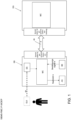
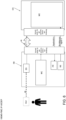
- Fig. 1 shows a dialysis machine DG as an example of a medical device that is to be controlled by a control component SB.
- the user makes inputs with control commands sb on the control component SB.
- the control component SB can be designed with an input interface ES.
- the input interface ES as in Fig. 1 indicated by dashed lines, externally and outside the control component SB, e.g. as a graphical user interface GUI, which exchanges data with the control component SB.
- the control commands sb recorded on the input interface are passed on to the local processor MC (here on the control component SB), which causes a message n to be generated, which is output on an output interface AS.
- the local processor MC here on the control component SB
- the message n contains a request to activate a control element BE and can, if necessary, include further information and data fields for notification.
- the control element BE indicated in the request is monitored. In particular, it is checked whether an activation has taken place. If so, a Confirmation signal b is transmitted to the processor MC of the control component SB.
- the processor of the control component SB is now able to decide whether or not the control element has been operated and activated as intended by the security algorithm. If so (confirmation signal b received), it can make local preparations so that the control command sb can be implemented and executed on the dialysis machine DG. To do this, it can in particular arrange for the control command sb to be sent to the dialysis machine DG via a secure data connection. After the control command sb has been received on the dialysis machine DG, the command can be executed there.
- the protection method is carried out completely on the control component SB.
- the user thus controls the dialysis machine remotely from the control component SB.
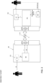
- FIG. 2 An alternative variant is in Fig. 2 shown.
- a four-eyes principle for controlling the dialysis machine DG can be implemented.
- a first user operates the control component SB and a second user operates the dialysis machine DG.
- a control command sb is recorded by the first user on the control component SB, e.g. on a user interface GUI, and forwarded to the processor MC, which in response generates the message n and sends it to the dialysis machine DG via the secure data connection.
- the processor MC of the dialysis machine DG there forwards the received message n to the local output interface AS for output (to the second user).
- the message n contains the request to activate a control element BE, which is now arranged on the dialysis machine DG so that it can be operated by the second user or by the same user.
- the control element BE is controlled by the processor MC according to the security algorithm in such a way that when activated correctly (e.g. when an activation signal is detected) it sends the confirmation signal b to the processor MC of the dialysis machine DG.
- control command sb is entered on the control component SB and the message n is also output on the control component SB, but the input is confirmed on the dialysis machine DG (e.g. via a dedicated confirmation switch).
- the message n can also be designed as a voice message for output on the control component SB (e.g. loud voice reproduction of the user input or control command with a request for confirmation).
- the confirmation signal b (from the dialysis machine DG) is forwarded to the control component SB, which in response transmits the (confirmed) control command sb to the processor MC of the dialysis machine DG.
- control component SB not only sends the message n generated locally (or in an alternative embodiment of the invention also on the dialysis machine DG) to the dialysis machine DG for the purpose of confirmation, but also the detected control command sb.
- the confirmation signal b does not have to be sent from the dialysis machine DG to the control component SB, since the dialysis machine already knows the control command sb and can execute it directly. If no confirmation signal was detected, the existing but unconfirmed control command sb is deleted and not executed.
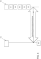
- Fig. 3 shows the sequence in an exemplary embodiment.
- the control command sb is recorded in step S1, preferably on the input interface ES.
- the message n is generated.
- the generated message n is output, preferably on the output interface AS.
- step S5 the control command is prepared for local execution on the dialysis machine DG in step S6.
- control component SB In order to keep the safety requirements for the control component SB as low as possible, it is preferably provided that as many steps as possible, in particular the evaluation, take place on the dialysis machine DG itself. It is therefore helpful if a first or second control element BE1 is formed on the dialysis machine, as described above in connection with Fig. 2 explained.
- the control component SB is therefore designed "only" for data input and output, while the evaluation logic, which checks whether the control element has been activated or not, is carried out on the dialysis machine itself. This makes it easier to comply with safety standards.
- Fig. 4 is an interaction diagram between the dialysis machine DG and the control component SB. In the Fig 4 In the variant shown, all steps of the protection procedure are carried out on the control component SB. Only after a successful confirmation has been detected on the control component SB, the control command sb is sent to the dialysis machine DG for execution there. Otherwise, the
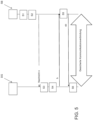
- Fig. 5 is a variant of the Fig. 4 described process, which corresponds to the structural design described above with reference to Fig. 2
- the protection system is designed here as a distributed system and the protection procedure is carried out in a distributed manner.
- a first section is carried out on the dialysis machine DG and a second section is carried out on the control component SB.
- the detection S1 and the generation of the message n are carried out in step S2 on the control component SB.
- the message n is transmitted to the dialysis machine DG. This is preferably also done via the secure data channel.
- the message n is then output in step S3 and the activation of the control element BE is checked in step S4.
- the confirmation signal b can be transmitted in one variant to the control component SB, which in response sends the control command sb to the dialysis machine DG in step S5 so that it can execute it locally in step 6.
- Fig. 6 is a variant of the Fig. 1 shown embodiment of the invention, in which the evaluation logic and the security algorithm are at least partially implemented on the dialysis machine DG.
- the entered control command sb is transmitted to the dialysis machine.
- the processor MC of the dialysis machine DG now converts the recorded control command sb into the message (voice or text) and sends this to the output interface AS of the control component SB.
- the confirmation signal b is sent back to the dialysis machine DG.
- the previously transmitted control command sb is thus considered to be confirmed.
- the control command sb is only implemented if the confirmation signal b has been received on the dialysis machine DG.
- control elements By additionally checking whether a control element has been operated in a preconfigured manner to confirm the recorded control command or not, inputs and control commands on external devices can also be additionally secured by appropriate hardware components.
- One advantage is that no new hardware components are required on the end device (e.g. in the form of new additional control elements). have to be provided, but that the already existing control elements can be used and only need to be modified by the processor.
- the components of the medical device DG and the control component SB can be distributed across several physical products.
Landscapes
- Health & Medical Sciences (AREA)
- Engineering & Computer Science (AREA)
- Biomedical Technology (AREA)
- Public Health (AREA)
- General Health & Medical Sciences (AREA)
- Urology & Nephrology (AREA)
- Heart & Thoracic Surgery (AREA)
- Emergency Medicine (AREA)
- Epidemiology (AREA)
- Primary Health Care (AREA)
- Medical Informatics (AREA)
- Hematology (AREA)
- Business, Economics & Management (AREA)
- Vascular Medicine (AREA)
- Anesthesiology (AREA)
- General Business, Economics & Management (AREA)
- Life Sciences & Earth Sciences (AREA)
- Animal Behavior & Ethology (AREA)
- Veterinary Medicine (AREA)
- Nuclear Medicine, Radiotherapy & Molecular Imaging (AREA)
- Surgery (AREA)
- External Artificial Organs (AREA)
Claims (16)
- Composant de commande (SB) pour la saisie sécurisée d'instructions de commande pour la commande d'au moins un appareil médical (DG), en particulier un appareil de dialyse, comprenant :- une interface d'entrée (ES) pour la saisie d'au moins une instruction de commande (sb) ;- une interface de sortie (AS) pour émettre un message (n) qui comprend une invitation à activer au moins un élément de commande (BE) ;- un processeur (MC) qui est conçu pour mettre en oeuvre un algorithme de sécurité, en ce que le processeur (MC) charge l'au moins un élément de commande (BE) d'une fonction supplémentaire pour vérifier si son activation a été détectée ;- au moins un élément de commande (BE) qui est commandé par le processeur (MC) et qui vérifie par conséquent si l'activation a été détectée et dans lequel le au moins un élément de commande (BE) est destiné, lors de la détection de l'activation, à envoyer respectivement un signal de confirmation (b) au processeur (MC) ;dans lequel le processeur (MC) provoque l'application de la au moins une instruction de commande (sb) sur le dispositif médical (DG) uniquement lorsqu'il a reçu le signal de confirmation (b) provenant du au moins un élément de commande (BE).
- Composant de commande (SB) selon la revendication 1, dans lequel l'interface d'entrée (ES) et l'au moins un élément de commande (BE) sont des composants séparés.
- Composant de commande (SB) selon au moins l'une des revendications précédentes, dans lequel le composant de commande (SB) est disposé séparément du dispositif médical (DG) et communique avec le dispositif médical (DG) via une liaison de communication sécurisée.
- Composant de commande (SB) selon au moins l'une des revendications précédentes, dans lequel l'interface de sortie (AS) est fusionnée avec l'interface d'entrée (ES) dans un composant.
- Composant de commande (SB) selon au moins l'une des revendications précédentes, dans lequel le message (n) comprend un élément de récapitulation qui reproduit les instructions de commande (sb) saisies sur l'interface d'entrée (ES).
- Procédé de protection pour le fonctionnement d'un composant de commande (SB) pour la saisie sécurisée d'instructions de commande (sb) pour la commande d'au moins un appareil médical (DG), en particulier un appareil de dialyse, le composant de commande (SB) étant disposé séparément de l'appareil médical (DG) et communiquant avec l'appareil médical (DG) par l'intermédiaire d'une liaison de communication sécurisée, comprenant les étapes de procédé suivantes :- la détection (S1) d'au moins une instruction de commande (sb) ;- générer (S2) un message (n), qui comprend une demande d'activation d'au moins un élément de commande (BE) ;- Édition (S3) du message (n) ;- vérifier (S4) si une activation a été détectée sur l'au moins un élément de commande (BE) et, si c'est le cas, répondre par l'affirmative :- préparer (S5) la au moins une instruction de commande (sb) détectée pour l'exécution (S6) sur le dispositif médical (DG).
- Procédé de protection selon la revendication de procédé précédente, dans lequel ladite au moins une instruction de commande (sb) est détectée en tant qu'entrée acoustique et/ou en tant qu'entrée sur une interface utilisateur.
- Procédé de protection selon au moins l'une des revendications de procédé précédentes, dans lequel le test (S4) est effectué en détectant si un signal d'accusé de réception (b) a été reçu.
- Procédé de protection selon au moins l'une des revendications de procédé précédentes, dans lequel on surveille si une activation sur l'au moins un élément de commande (BE) a déjà été détectée dans le temps avant l'émission du message (n) et, dans l'affirmative : on émet un avertissement.
- Procédé de protection selon au moins l'une des revendications de procédé précédentes, dans lequel la saisie de l'au moins une instruction de commande (sb) n'est pas effectuée sur l'élément de commande (BE) et/ou dans lequel l'activation n'est pas saisie sur l'interface d'entrée (ES) sur laquelle l'au moins une instruction de commande (sb) est saisie.
- Procédé de protection selon au moins l'une des revendications de procédé précédentes, dans lequel ladite au moins une instruction de commande (sb) et/ou ledit message (n) comprennent un horodatage.
- Procédé de protection selon au moins l'une des revendications de procédé précédentes, dans lequel la demande d'activation d'au moins un élément de commande (BE) parmi un groupe d'éléments de commande est générée dynamiquement selon un schéma préconfiguré qui est enregistré dans une mémoire.
- Procédé de protection selon au moins l'une des revendications de procédé précédentes, dans lequel la demande d'activation d'au moins un élément de commande (BE) est une demande d'activation de plusieurs éléments de commande (BE) dans une séquence définie ou pour une activation simultanée.
- Procédé de protection selon au moins l'une des revendications de procédé précédentes, qui est mis en oeuvre dans une zone de mémoire protégée du composant de commande (SB).
- Programme informatique pour un dispositif médical (DG) et/ou un composant de commande (SB), qui peut être chargé dans une mémoire interne d'un processeur (MC) et qui comprend des routines logicielles avec lesquelles les étapes du procédé selon les revendications de procédé précédentes sont exécutées lorsque les routines logicielles sont exécutées sur le processeur (MC).
- Système de commande pour la saisie sécurisée d'instructions de commande (sb) sur un composant de commande (SB), qui est conçu pour commander au moins un appareil médical (DG), en particulier un appareil de dialyse, comprenant :- d'au moins un dispositif médical (DG) ;- le composant de commande (SB) ;- au moins un élément de commande (BE) ;dans lequel le composant de commande (SB) est disposé séparément du dispositif médical (DG) et communique avec le dispositif médical (DG) par l'intermédiaire d'une liaison de communication sécurisée etdans lequel, sur le composant de commande (SB) ou sur le dispositif médical (DG), une instruction de commande (sb) est détectée et un message (n) est généré, qui comprend une demande d'activation de l'au moins un élément de commande (BE) ;et dans lequel le message (n) généré est émis sur le composant de commande (SB) ou sur l'appareil médical (DG) ;et dans lequel on vérifie sur l'au moins un élément de commande (BE) si une activation a été détectée et dans l'affirmative :
la confirmation de l'au moins une instruction de commande (sb) détectée pour provoquer son application sur le dispositif médical (DG).
Applications Claiming Priority (2)
| Application Number | Priority Date | Filing Date | Title |
|---|---|---|---|
| DE102018123012.5A DE102018123012A1 (de) | 2018-09-19 | 2018-09-19 | Sichere Eingabe auf einem Steuerungsbauteil für ein Dialysegerät |
| PCT/EP2019/074349 WO2020058078A1 (fr) | 2018-09-19 | 2019-09-12 | Entrée sécurisée sur un composant de commande d'un dispositif de dialyse |
Publications (2)
| Publication Number | Publication Date |
|---|---|
| EP3853864A1 EP3853864A1 (fr) | 2021-07-28 |
| EP3853864B1 true EP3853864B1 (fr) | 2024-10-30 |
Family
ID=67956779
Family Applications (1)
| Application Number | Title | Priority Date | Filing Date |
|---|---|---|---|
| EP19769129.8A Active EP3853864B1 (fr) | 2018-09-19 | 2019-09-12 | Entrée sécurisée sur un composant de commande d'un dispositif de dialyse |
Country Status (5)
| Country | Link |
|---|---|
| US (2) | US11969531B2 (fr) |
| EP (1) | EP3853864B1 (fr) |
| CN (1) | CN112753075A (fr) |
| DE (1) | DE102018123012A1 (fr) |
| WO (1) | WO2020058078A1 (fr) |
Families Citing this family (1)
| Publication number | Priority date | Publication date | Assignee | Title |
|---|---|---|---|---|
| CN113877081B (zh) | 2020-07-03 | 2024-04-19 | 中硼(厦门)医疗器械有限公司 | 中子捕获治疗设备及其监测系统运行步骤 |
Family Cites Families (10)
| Publication number | Priority date | Publication date | Assignee | Title |
|---|---|---|---|---|
| US5792204A (en) | 1996-05-08 | 1998-08-11 | Pacesetter, Inc. | Methods and apparatus for controlling an implantable device programmer using voice commands |
| DE19849787C1 (de) | 1998-10-28 | 2000-02-24 | Fresenius Medical Care De Gmbh | Blutbehandlungsgerät |
| WO2004093648A2 (fr) * | 2003-04-18 | 2004-11-04 | Insulet Corporation | Interface utilisateur pour unite de telecommande de pompe de perfusion et son procede d'utilisation |
| CN101801438B (zh) * | 2007-07-20 | 2013-08-07 | 梅丁格有限公司 | 可手动操作的便携式输注设备 |
| US20090221890A1 (en) * | 2008-02-28 | 2009-09-03 | Daniel Saffer | Diabetes Management System |
| US10195343B2 (en) * | 2010-02-05 | 2019-02-05 | Deka Products Limited Partnership | Devices, methods and systems for wireless control of medical devices |
| US20160228633A1 (en) * | 2013-09-27 | 2016-08-11 | Smiths Medical Asd, Inc. | Infusion pump with touchless user interface and related methods |
| US9364185B2 (en) * | 2014-01-15 | 2016-06-14 | Roche Diabetes Care, Inc. | Low energy wireless communication systems and methods for medical devices |
| DE102015104819B4 (de) * | 2015-03-27 | 2018-01-25 | Medineering Gmbh | Haltearm für medizinische Zwecke mit abnehmbarer Bedieneinrichtung, sowie Bedieneinrichtung hierfür |
| DE102017111296B3 (de) * | 2017-05-23 | 2018-08-02 | Medineering Gmbh | Robotischer Manipulator zur Führung eines Endoskops mit Parallelkinematik |
-
2018
- 2018-09-19 DE DE102018123012.5A patent/DE102018123012A1/de not_active Ceased
-
2019
- 2019-08-23 US US16/549,124 patent/US11969531B2/en active Active
- 2019-09-12 WO PCT/EP2019/074349 patent/WO2020058078A1/fr not_active Ceased
- 2019-09-12 EP EP19769129.8A patent/EP3853864B1/fr active Active
- 2019-09-12 CN CN201980061687.0A patent/CN112753075A/zh active Pending
-
2024
- 2024-03-20 US US18/611,540 patent/US20240226402A1/en active Pending
Also Published As
| Publication number | Publication date |
|---|---|
| US20200086029A1 (en) | 2020-03-19 |
| US20240226402A1 (en) | 2024-07-11 |
| EP3853864A1 (fr) | 2021-07-28 |
| US11969531B2 (en) | 2024-04-30 |
| CN112753075A (zh) | 2021-05-04 |
| DE102018123012A1 (de) | 2020-03-19 |
| WO2020058078A1 (fr) | 2020-03-26 |
Similar Documents
| Publication | Publication Date | Title |
|---|---|---|
| EP1899878B1 (fr) | Systeme de traitement medical comportant un dispositif pour preparer des donnees specifiques de patients | |
| DE19904090C2 (de) | Verfahren und Vorrichtung zur automatischen Steuerung und Verwaltung medizinischer Geräte und Anlagen | |
| EP1325458B1 (fr) | Systeme et procede de commande centrale de dispositifs utilises lors d'une operation | |
| EP2732392B1 (fr) | Procédé et dispositif de surveillance et commande à distance d'appareils médicaux de gestion de fluides | |
| EP3542367B1 (fr) | Traitement concerté des alarmes d'un ensemble d'appareils de dialyse | |
| DE19934514C5 (de) | Verfahren zum Konfigurieren eines an einen Feldbus angeschlossenen Busteilnehmers | |
| DE102011121668A1 (de) | Verfahren und Vorrichtung zur Vorbereitung von medizinischen Behandlungsvorrichtungen | |
| EP3853864B1 (fr) | Entrée sécurisée sur un composant de commande d'un dispositif de dialyse | |
| EP2375636A1 (fr) | Dispositif et procédé de configuration d'un système de bus | |
| EP3853863B1 (fr) | Commande sécurisée d'appareils de dialyse | |
| EP2491492A1 (fr) | Système d'automatisation et procédé pour faire fonctionner un système d'automatisation | |
| EP2094330B1 (fr) | Dispositif de traitement sanguin, élément mémoire à utiliser avec le dispositif de traitement sanguin et combinaison du dispositif de traitement sanguin et de l'élément mémoire | |
| EP3433776B1 (fr) | Commande à distance des messages d'un appareil de dialyse | |
| EP3747018B1 (fr) | Surveillance de manipulation pour un appareil de dialyse | |
| DE102016006090A1 (de) | Medizinische Vorrichtung mit zeitgesteuerter Startfunktion | |
| EP3374892B1 (fr) | Appareil médical à assistance de l'utilisateur et procédé | |
| EP3818537A1 (fr) | Procédé de fonctionnement d'un dispositif médical et dispositif médical fonctionnant selon ce procédé | |
| DE102008043534A1 (de) | Zentrale Gerätesteuerung im Operationssaal | |
| WO2012025323A1 (fr) | Procédé de transmission d'une communication | |
| EP4335127B1 (fr) | Procédé mis en oeuvre par ordinateur destiné au fonctionnement d'un terminal à haute disponibilité dans un réseau | |
| WO2004031694A1 (fr) | Procede pour faire fonctionner un dispositif de mesure de position et dispositif de mesure de position correspondant | |
| WO2024213476A1 (fr) | Fourniture d'un signal d'entrée pour un collecteur de signal | |
| DE102016114539B4 (de) | Behandlung von wiederholten Fehlermeldungen eines Dialysegerätes | |
| DE102023207569A1 (de) | Verfahren zum Verwalten einer Gerätegruppe mit zumindest zwei Geräten mittels eines Verwaltungssystems, Computerprogrammprodukt, computerlesbares Speichermedium sowie Verwaltungssystem | |
| WO2019201827A1 (fr) | Mise à niveau sur support vidéo de machines de dialyse |
Legal Events
| Date | Code | Title | Description |
|---|---|---|---|
| STAA | Information on the status of an ep patent application or granted ep patent |
Free format text: STATUS: UNKNOWN |
|
| STAA | Information on the status of an ep patent application or granted ep patent |
Free format text: STATUS: THE INTERNATIONAL PUBLICATION HAS BEEN MADE |
|
| PUAI | Public reference made under article 153(3) epc to a published international application that has entered the european phase |
Free format text: ORIGINAL CODE: 0009012 |
|
| STAA | Information on the status of an ep patent application or granted ep patent |
Free format text: STATUS: REQUEST FOR EXAMINATION WAS MADE |
|
| 17P | Request for examination filed |
Effective date: 20210303 |
|
| AK | Designated contracting states |
Kind code of ref document: A1 Designated state(s): AL AT BE BG CH CY CZ DE DK EE ES FI FR GB GR HR HU IE IS IT LI LT LU LV MC MK MT NL NO PL PT RO RS SE SI SK SM TR |
|
| DAV | Request for validation of the european patent (deleted) | ||
| DAX | Request for extension of the european patent (deleted) | ||
| GRAP | Despatch of communication of intention to grant a patent |
Free format text: ORIGINAL CODE: EPIDOSNIGR1 |
|
| STAA | Information on the status of an ep patent application or granted ep patent |
Free format text: STATUS: GRANT OF PATENT IS INTENDED |
|
| INTG | Intention to grant announced |
Effective date: 20240523 |
|
| GRAS | Grant fee paid |
Free format text: ORIGINAL CODE: EPIDOSNIGR3 |
|
| GRAA | (expected) grant |
Free format text: ORIGINAL CODE: 0009210 |
|
| STAA | Information on the status of an ep patent application or granted ep patent |
Free format text: STATUS: THE PATENT HAS BEEN GRANTED |
|
| AK | Designated contracting states |
Kind code of ref document: B1 Designated state(s): AL AT BE BG CH CY CZ DE DK EE ES FI FR GB GR HR HU IE IS IT LI LT LU LV MC MK MT NL NO PL PT RO RS SE SI SK SM TR |
|
| REG | Reference to a national code |
Ref country code: GB Ref legal event code: FG4D Free format text: NOT ENGLISH |
|
| REG | Reference to a national code |
Ref country code: CH Ref legal event code: EP |
|
| REG | Reference to a national code |
Ref country code: IE Ref legal event code: FG4D Free format text: LANGUAGE OF EP DOCUMENT: GERMAN |
|
| REG | Reference to a national code |
Ref country code: DE Ref legal event code: R096 Ref document number: 502019012404 Country of ref document: DE |
|
| P01 | Opt-out of the competence of the unified patent court (upc) registered |
Free format text: CASE NUMBER: APP_60357/2024 Effective date: 20241108 |
|
| REG | Reference to a national code |
Ref country code: LT Ref legal event code: MG9D |
|
| REG | Reference to a national code |
Ref country code: NL Ref legal event code: MP Effective date: 20241030 |
|
| PG25 | Lapsed in a contracting state [announced via postgrant information from national office to epo] |
Ref country code: IS Free format text: LAPSE BECAUSE OF FAILURE TO SUBMIT A TRANSLATION OF THE DESCRIPTION OR TO PAY THE FEE WITHIN THE PRESCRIBED TIME-LIMIT Effective date: 20250228 Ref country code: HR Free format text: LAPSE BECAUSE OF FAILURE TO SUBMIT A TRANSLATION OF THE DESCRIPTION OR TO PAY THE FEE WITHIN THE PRESCRIBED TIME-LIMIT Effective date: 20241030 Ref country code: PT Free format text: LAPSE BECAUSE OF FAILURE TO SUBMIT A TRANSLATION OF THE DESCRIPTION OR TO PAY THE FEE WITHIN THE PRESCRIBED TIME-LIMIT Effective date: 20250228 |
|
| PG25 | Lapsed in a contracting state [announced via postgrant information from national office to epo] |
Ref country code: FI Free format text: LAPSE BECAUSE OF FAILURE TO SUBMIT A TRANSLATION OF THE DESCRIPTION OR TO PAY THE FEE WITHIN THE PRESCRIBED TIME-LIMIT Effective date: 20241030 Ref country code: NL Free format text: LAPSE BECAUSE OF FAILURE TO SUBMIT A TRANSLATION OF THE DESCRIPTION OR TO PAY THE FEE WITHIN THE PRESCRIBED TIME-LIMIT Effective date: 20241030 |
|
| PG25 | Lapsed in a contracting state [announced via postgrant information from national office to epo] |
Ref country code: BG Free format text: LAPSE BECAUSE OF FAILURE TO SUBMIT A TRANSLATION OF THE DESCRIPTION OR TO PAY THE FEE WITHIN THE PRESCRIBED TIME-LIMIT Effective date: 20241030 |
|
| PG25 | Lapsed in a contracting state [announced via postgrant information from national office to epo] |
Ref country code: ES Free format text: LAPSE BECAUSE OF FAILURE TO SUBMIT A TRANSLATION OF THE DESCRIPTION OR TO PAY THE FEE WITHIN THE PRESCRIBED TIME-LIMIT Effective date: 20241030 |
|
| PG25 | Lapsed in a contracting state [announced via postgrant information from national office to epo] |
Ref country code: NO Free format text: LAPSE BECAUSE OF FAILURE TO SUBMIT A TRANSLATION OF THE DESCRIPTION OR TO PAY THE FEE WITHIN THE PRESCRIBED TIME-LIMIT Effective date: 20250130 |
|
| PG25 | Lapsed in a contracting state [announced via postgrant information from national office to epo] |
Ref country code: LV Free format text: LAPSE BECAUSE OF FAILURE TO SUBMIT A TRANSLATION OF THE DESCRIPTION OR TO PAY THE FEE WITHIN THE PRESCRIBED TIME-LIMIT Effective date: 20241030 Ref country code: GR Free format text: LAPSE BECAUSE OF FAILURE TO SUBMIT A TRANSLATION OF THE DESCRIPTION OR TO PAY THE FEE WITHIN THE PRESCRIBED TIME-LIMIT Effective date: 20250131 |
|
| PG25 | Lapsed in a contracting state [announced via postgrant information from national office to epo] |
Ref country code: PL Free format text: LAPSE BECAUSE OF FAILURE TO SUBMIT A TRANSLATION OF THE DESCRIPTION OR TO PAY THE FEE WITHIN THE PRESCRIBED TIME-LIMIT Effective date: 20241030 |
|
| PG25 | Lapsed in a contracting state [announced via postgrant information from national office to epo] |
Ref country code: RS Free format text: LAPSE BECAUSE OF FAILURE TO SUBMIT A TRANSLATION OF THE DESCRIPTION OR TO PAY THE FEE WITHIN THE PRESCRIBED TIME-LIMIT Effective date: 20250130 |
|
| PG25 | Lapsed in a contracting state [announced via postgrant information from national office to epo] |
Ref country code: SM Free format text: LAPSE BECAUSE OF FAILURE TO SUBMIT A TRANSLATION OF THE DESCRIPTION OR TO PAY THE FEE WITHIN THE PRESCRIBED TIME-LIMIT Effective date: 20241030 |
|
| PG25 | Lapsed in a contracting state [announced via postgrant information from national office to epo] |
Ref country code: DK Free format text: LAPSE BECAUSE OF FAILURE TO SUBMIT A TRANSLATION OF THE DESCRIPTION OR TO PAY THE FEE WITHIN THE PRESCRIBED TIME-LIMIT Effective date: 20241030 |
|
| PG25 | Lapsed in a contracting state [announced via postgrant information from national office to epo] |
Ref country code: EE Free format text: LAPSE BECAUSE OF FAILURE TO SUBMIT A TRANSLATION OF THE DESCRIPTION OR TO PAY THE FEE WITHIN THE PRESCRIBED TIME-LIMIT Effective date: 20241030 |
|
| PG25 | Lapsed in a contracting state [announced via postgrant information from national office to epo] |
Ref country code: RO Free format text: LAPSE BECAUSE OF FAILURE TO SUBMIT A TRANSLATION OF THE DESCRIPTION OR TO PAY THE FEE WITHIN THE PRESCRIBED TIME-LIMIT Effective date: 20241030 |
|
| PG25 | Lapsed in a contracting state [announced via postgrant information from national office to epo] |
Ref country code: SK Free format text: LAPSE BECAUSE OF FAILURE TO SUBMIT A TRANSLATION OF THE DESCRIPTION OR TO PAY THE FEE WITHIN THE PRESCRIBED TIME-LIMIT Effective date: 20241030 |
|
| PG25 | Lapsed in a contracting state [announced via postgrant information from national office to epo] |
Ref country code: CZ Free format text: LAPSE BECAUSE OF FAILURE TO SUBMIT A TRANSLATION OF THE DESCRIPTION OR TO PAY THE FEE WITHIN THE PRESCRIBED TIME-LIMIT Effective date: 20241030 |
|
| PG25 | Lapsed in a contracting state [announced via postgrant information from national office to epo] |
Ref country code: IT Free format text: LAPSE BECAUSE OF FAILURE TO SUBMIT A TRANSLATION OF THE DESCRIPTION OR TO PAY THE FEE WITHIN THE PRESCRIBED TIME-LIMIT Effective date: 20241030 |
|
| REG | Reference to a national code |
Ref country code: DE Ref legal event code: R097 Ref document number: 502019012404 Country of ref document: DE |
|
| PLBE | No opposition filed within time limit |
Free format text: ORIGINAL CODE: 0009261 |
|
| STAA | Information on the status of an ep patent application or granted ep patent |
Free format text: STATUS: NO OPPOSITION FILED WITHIN TIME LIMIT |
|
| PG25 | Lapsed in a contracting state [announced via postgrant information from national office to epo] |
Ref country code: SE Free format text: LAPSE BECAUSE OF FAILURE TO SUBMIT A TRANSLATION OF THE DESCRIPTION OR TO PAY THE FEE WITHIN THE PRESCRIBED TIME-LIMIT Effective date: 20241030 |
|
| 26N | No opposition filed |
Effective date: 20250731 |
|
| PGFP | Annual fee paid to national office [announced via postgrant information from national office to epo] |
Ref country code: DE Payment date: 20250820 Year of fee payment: 7 |
|
| PGFP | Annual fee paid to national office [announced via postgrant information from national office to epo] |
Ref country code: GB Payment date: 20250820 Year of fee payment: 7 |
|
| PGFP | Annual fee paid to national office [announced via postgrant information from national office to epo] |
Ref country code: FR Payment date: 20250820 Year of fee payment: 7 |