EP3853960B1 - Système de distribution électrique pour une installation hydraulique - Google Patents
Système de distribution électrique pour une installation hydraulique Download PDFInfo
- Publication number
- EP3853960B1 EP3853960B1 EP19812706.0A EP19812706A EP3853960B1 EP 3853960 B1 EP3853960 B1 EP 3853960B1 EP 19812706 A EP19812706 A EP 19812706A EP 3853960 B1 EP3853960 B1 EP 3853960B1
- Authority
- EP
- European Patent Office
- Prior art keywords
- voltage
- bus
- supply system
- zone
- energy
- Prior art date
- Legal status (The legal status is an assumption and is not a legal conclusion. Google has not performed a legal analysis and makes no representation as to the accuracy of the status listed.)
- Active
Links
Images









Classifications
-
- B—PERFORMING OPERATIONS; TRANSPORTING
- B63—SHIPS OR OTHER WATERBORNE VESSELS; RELATED EQUIPMENT
- B63H—MARINE PROPULSION OR STEERING
- B63H21/00—Use of propulsion power plant or units on vessels
- B63H21/20—Use of propulsion power plant or units on vessels the vessels being powered by combinations of different types of propulsion units
-
- B—PERFORMING OPERATIONS; TRANSPORTING
- B63—SHIPS OR OTHER WATERBORNE VESSELS; RELATED EQUIPMENT
- B63H—MARINE PROPULSION OR STEERING
- B63H21/00—Use of propulsion power plant or units on vessels
- B63H21/12—Use of propulsion power plant or units on vessels the vessels being motor-driven
- B63H21/16—Use of propulsion power plant or units on vessels the vessels being motor-driven relating to gas turbines
-
- B—PERFORMING OPERATIONS; TRANSPORTING
- B63—SHIPS OR OTHER WATERBORNE VESSELS; RELATED EQUIPMENT
- B63H—MARINE PROPULSION OR STEERING
- B63H21/00—Use of propulsion power plant or units on vessels
- B63H21/12—Use of propulsion power plant or units on vessels the vessels being motor-driven
- B63H21/17—Use of propulsion power plant or units on vessels the vessels being motor-driven by electric motor
-
- B—PERFORMING OPERATIONS; TRANSPORTING
- B63—SHIPS OR OTHER WATERBORNE VESSELS; RELATED EQUIPMENT
- B63H—MARINE PROPULSION OR STEERING
- B63H23/00—Transmitting power from propulsion power plant to propulsive elements
- B63H23/22—Transmitting power from propulsion power plant to propulsive elements with non-mechanical gearing
- B63H23/24—Transmitting power from propulsion power plant to propulsive elements with non-mechanical gearing electric
-
- H—ELECTRICITY
- H02—GENERATION; CONVERSION OR DISTRIBUTION OF ELECTRIC POWER
- H02J—ELECTRIC POWER NETWORKS; CIRCUIT ARRANGEMENTS OR SYSTEMS FOR SUPPLYING OR DISTRIBUTING ELECTRIC POWER; SYSTEMS FOR STORING ELECTRIC ENERGY
- H02J1/00—Circuit arrangements for DC mains or DC distribution networks
- H02J1/08—Three-wire DC power distribution systems; Systems having more than three wires
- H02J1/082—DC supplies with two or more different DC voltage levels
-
- H—ELECTRICITY
- H02—GENERATION; CONVERSION OR DISTRIBUTION OF ELECTRIC POWER
- H02J—ELECTRIC POWER NETWORKS; CIRCUIT ARRANGEMENTS OR SYSTEMS FOR SUPPLYING OR DISTRIBUTING ELECTRIC POWER; SYSTEMS FOR STORING ELECTRIC ENERGY
- H02J1/00—Circuit arrangements for DC mains or DC distribution networks
- H02J1/10—Parallel operation of DC sources
-
- B—PERFORMING OPERATIONS; TRANSPORTING
- B63—SHIPS OR OTHER WATERBORNE VESSELS; RELATED EQUIPMENT
- B63H—MARINE PROPULSION OR STEERING
- B63H21/00—Use of propulsion power plant or units on vessels
- B63H21/20—Use of propulsion power plant or units on vessels the vessels being powered by combinations of different types of propulsion units
- B63H2021/202—Use of propulsion power plant or units on vessels the vessels being powered by combinations of different types of propulsion units of hybrid electric type
- B63H2021/207—Use of propulsion power plant or units on vessels the vessels being powered by combinations of different types of propulsion units of hybrid electric type the second power unit being a gas turbine
-
- H—ELECTRICITY
- H02—GENERATION; CONVERSION OR DISTRIBUTION OF ELECTRIC POWER
- H02J—ELECTRIC POWER NETWORKS; CIRCUIT ARRANGEMENTS OR SYSTEMS FOR SUPPLYING OR DISTRIBUTING ELECTRIC POWER; SYSTEMS FOR STORING ELECTRIC ENERGY
- H02J2105/00—Networks for supplying or distributing electric power characterised by their spatial reach or by the load
- H02J2105/30—Networks for supplying or distributing electric power characterised by their spatial reach or by the load the load networks being external to vehicles, i.e. exchanging power with vehicles
- H02J2105/31—Networks for supplying or distributing electric power characterised by their spatial reach or by the load the load networks being external to vehicles, i.e. exchanging power with vehicles for ships or vessels
-
- Y—GENERAL TAGGING OF NEW TECHNOLOGICAL DEVELOPMENTS; GENERAL TAGGING OF CROSS-SECTIONAL TECHNOLOGIES SPANNING OVER SEVERAL SECTIONS OF THE IPC; TECHNICAL SUBJECTS COVERED BY FORMER USPC CROSS-REFERENCE ART COLLECTIONS [XRACs] AND DIGESTS
- Y02—TECHNOLOGIES OR APPLICATIONS FOR MITIGATION OR ADAPTATION AGAINST CLIMATE CHANGE
- Y02T—CLIMATE CHANGE MITIGATION TECHNOLOGIES RELATED TO TRANSPORTATION
- Y02T70/00—Maritime or waterways transport
- Y02T70/50—Measures to reduce greenhouse gas emissions related to the propulsion system
- Y02T70/5218—Less carbon-intensive fuels, e.g. natural gas, biofuels
- Y02T70/5236—Renewable or hybrid-electric solutions
Definitions
- the invention relates to an energy supply system for a water-based facility, in particular a floating facility.
- Floating facilities include, for example, ships, submarines, oil platforms, and/or gas platforms. Examples of ships include cruise ships, frigates, container ships, aircraft carriers, icebreakers, etc.
- Floating facilities are water-based facilities. Oil platforms or gas platforms located on the seabed are examples of water-based facilities.
- the invention also relates to a corresponding method for operating this energy supply system.
- An energy supply system for a water-based facility or a floating facility has energy sources. References to a floating facility below also include water-based facilities and vice versa. Examples of energy sources include a diesel generator, a fuel cell, a battery/accumulator, a flywheel, etc.
- the diesel in the diesel generator can be operated with heavy fuel oil and/or LNG, for example.
- the energy supply system is intended, for example, to supply electrical energy to a drive system of the floating facility or to auxiliary systems or other consumers such as air conditioning, lighting, automation systems, etc.
- the energy supply system can be designed in such a way that, even in the event of a power source failure, at least emergency operation of the floating facility is possible.
- the energy supply of a floating facility has, in particular, an on-board electrical system.
- the on-board electrical system (the electrical on-board network) serves to supply electrical energy to the floating facility.
- a floating facility if a floating facility is capable of maintaining its position, it will have multiple propulsion systems. These propulsion systems will, in particular, include a propeller or a water jet (border jet). These propulsion systems for maintaining the ship's position in the water must, in particular, be kept operational independently of one another. If this floating facility has, for example, two or more propulsion systems in the stern area, such as two POD drives or two propellers with shafts projecting from the ship's hull, which are driven by an electric motor and/or a diesel engine with a shaft generator, it is advantageous if these can be supplied with electrical energy independently of one another in the event of a failure in one of the propulsion systems.
- propulsion systems will, in particular, include a propeller or a water jet (border jet). These propulsion systems for maintaining the ship's position in the water must, in particular, be kept operational independently of one another.
- this floating facility has, for example, two or more propulsion systems in the stern area, such as two POD drives or two propeller
- a power distribution system on a ship has a first medium-voltage bus and a second medium-voltage bus.
- the second medium-voltage bus has no direct connection to the first medium-voltage bus.
- the power distribution system also has a first low-voltage AC bus and a first power converter between the first medium-voltage bus and the first AC bus to enable power flow from the first medium-voltage bus to the first AC bus.
- the power distribution system also has a second AC bus and a second power converter between the second medium-voltage bus and the second AC bus to enable power flow from the second medium-voltage bus to the second AC bus.
- a device for distributing stored electrical energy on a ship which also includes one or more AC consumers.
- a DC network with a plurality of electrical energy storage elements is provided to enable the supply of one or more AC consumers with stored electrical energy.
- several interrupter systems are provided to switch off one or more electrical auxiliary power sources.
- the electric drive shaft has at least one variable-speed generator for generating a voltage with variable amplitude and variable frequency, and at least one variable-speed drive motor supplied with this voltage.
- the generator has, for example, a superconductor winding, in particular a high-temperature superconductor (HTS) winding.
- HTS high-temperature superconductor
- a ship propulsion system having at least a first and a second electrical drive shaft (electrical shaft) for driving a respective propulsion unit, in particular a waterjet or, for example, a propeller, wherein each of the electrical drive shafts has at least one variable-speed generator driven by an internal combustion engine for generating a motor voltage with variable amplitude and variable frequency and at least one variable-speed drive motor supplied with this motor voltage and coupled to a propulsion unit, wherein the first and the second drive shaft can be switched from a first operating state in which they are electrically separated from one another to a second operating state in which they are electrically coupled to one another in such a way that energy can be transferred from the at least one generator of one drive shaft to the at least one drive motor of the other drive shaft.
- a propulsion system for a ship wherein the ship has an electrical on-board network with a fixed on-board network frequency, wherein the propulsion system comprises a propulsion electric motor for driving the ship, a frequency converter via which electrical energy from the on-board network can be supplied to the propulsion electric motor, a propulsion machine, a drive generator drivable by the drive machine, and an electrical shaft for connecting the drive electric motor to the drive generator, wherein the drive electric motor can be driven selectively by the frequency converter or by the drive generator.
- AC or DC In on-board electrical systems, electrical energy is often required at different voltage levels and/or in different voltage forms (AC or DC).
- primary energy is provided from one or more internal combustion engines, for example, and converted into electrical energy by one or more three-phase generators (asynchronous generators or synchronous generators).
- This electrical energy is generated primarily at the highest voltage level available in the on-board network (upper voltage level of the supply network).
- Transformers and/or DC/DC converters for example, are used to generate additional voltage levels.
- the transformers are generally heavy and bulky, have losses of approximately 1%, and the input and output frequencies are always identical. For example, the entire generated generator power is fed in via the upper voltage level and distributed to a main energy bus.
- the electrical energy is distributed primarily via one or more switchboards.
- the frequency of a lower network is the same as the frequency of the upper network.
- the lower network differs from the upper network in terms of voltage, with the upper network having a higher voltage than the lower network.
- the use of an AC grid with an AC power bus for the distribution of electrical energy can be disadvantageous if the frequency is variable in the upper voltage level. Variable frequencies are particularly the result of variable-speed combustion engines.
- the energy is transmitted via the upper AC
- the main power bus is therefore transmitted via the upper voltage level.
- the energy can be distributed via a switchgear.
- An AC switchgear is used to distribute AC.
- the voltage level of the power bus or the voltage level depends largely on the installed capacity.
- the various consumers are fed, and the lower voltage levels are supplied with energy.
- Transformers are required in AC networks to connect the different voltage levels, ensuring that the voltage levels have the same frequency. The transformation ratio of the transformer used determines the voltage ratio.
- Diesel engines On some ships it is difficult to use diesel as an internal combustion engine to drive a generator to produce electrical energy because diesel engines are heavy. Diesel engines also take up space. Challenges can also arise from restrictions on installed power and/or the voltage or frequency of the electrical energy generated having to be kept within a certain range during operation. Some advantages can be achieved in this regard using an electric shaft. With the electric shaft there is a direct coupling between the generator and the drive motor. The drive motor is coupled to the generator in such a way that there is proportionality between the frequency of the generator and the drive motor (engine). Proportionality depends on the number of pole pairs of the generator or rotor.
- One object of the present invention is therefore to provide a flexible energy supply system and a flexible method for operating such an energy supply system.
- a further object of the present invention is to provide an energy supply system which is improved with regard to the weight of the equipment required for the energy supply system.
- a power supply system for a water-based facility comprises an electrical shaft, wherein the electrical shaft is connectable to a first DC voltage bus for a first DC voltage and to a second DC voltage bus for a second DC voltage, wherein the electrical shaft comprises at least one variable-speed generator driven by an internal combustion engine for generating a motor voltage with variable amplitude and variable frequency and at least one variable-speed drive motor supplied with this motor voltage and coupled to a propulsion unit.
- the gas turbines are therefore, in particular, assigned to part of an electrical shaft or an electrical shaft.
- a ship has two to four propellers. Each propeller typically has a power output of between 4 MW and 12 MW, and in particular at least 5 MW.
- a hotel load, especially on a cruise ship, or the remaining electrical power of the water-based facility is significantly lower than the propulsion power. This can, for example, be a ratio of one to ten, or a required power of less than 10 MW.
- a typical turbogenerator speed is 3,000 revolutions per minute or higher.
- a propeller speed for example, is between 100 and 300 revolutions per minute.
- the power supply system may also include a drive motor with a low-voltage (LV) winding and a medium-voltage (MV) winding.
- the medium-voltage winding may be supplied from the LVDC bus via an inverter.
- the energy supply system for a water-based facility has a first DC voltage bus for a first DC voltage and a second DC voltage bus for a second DC voltage.
- first DC voltage is suitable or provided for a first DC voltage level
- second DC voltage bus is suitable or provided for a second DC voltage level.
- the first DC voltage level is in particular higher than the second DC voltage level.
- the first DC voltage level therefore corresponds to the first DC voltage bus and the second DC voltage level corresponds to the second DC voltage bus.
- the DC voltage levels differ by a factor of between 5 and 50. The same applies to a water-based or floating facility, in particular a ship, which has an energy supply system in one of the described embodiments.
- the floating or water-based facility and/or the energy supply system has a first zone and a second zone.
- a floating facility should also be understood to mean a water-based facility in the following.
- the floating facility can also have more than two zones.
- the type of zones can vary.
- a zone can be a fire zone.
- Zones can be separated from one another by one or more bulkheads. Chambers are formed in this way, which can serve, for example, to protect against fire and/or to protect against the sinking of the floating or water-based facility.
- a bulkhead or bulkheads can be designed or constructed to be airtight and/or liquid-tight and/or fire-retardant.
- a floating facility such as a ship
- zones or chambers are formed.
- a chamber can represent a zone, just as a zone can represent a chamber.
- the energy supply system for the floating or water-based facility comprises a first energy source and a second energy source, wherein the first energy source is provided in the first zone for supplying at least one DC voltage bus of the at least two DC voltage buses, and wherein the second energy source is provided in the second zone for supplying at least one DC voltage bus of the at least two DC voltage buses.
- the energy supply system it is at least partially structured according to zones.
- the spatial structure corresponds to the zoning of at least two zones. Zones of the water-based facility are created, in particular, by a structural feature such as a bulkhead.
- the energy supply system is structured, in particular, by switching devices that can establish or disconnect an electrical connection. Sections in the energy supply system can be formed by such switching devices.
- secondary energy sources are selected so that they can react more quickly to load fluctuations if necessary.
- the load includes, for example, at least one drive motor for driving the floating facility and/or other electrical consumers of the floating facility, for example pumps, compressors, air conditioning systems, cable winches, on-board electronics, etc.
- electrical consumers for, for example, the air conditioning, laundry, lighting, etc. are also referred to as the hotel load.
- the energy supply system can comprise multiple energy sources of the same type.
- energy sources of different types can be located in different zones. This can increase the reliability of supply within the floating facility, for example, in emergencies and/or in the event of a fault.
- first DC bus and a second DC bus in the floating device, electrical energy can be easily transferred from one bus to the other without unnecessary losses. This is particularly advantageous in the event of a fault where one or more energy sources for the first bus fail. If energy levels are linked via an AC connection, this can lead to higher losses, particularly in the event of a fault.
- DC networks the energy is first rectified in order to be distributed across the upper DC voltage (conversion 1). An AC voltage must then be generated from the DC voltage using an inverter (conversion 2).
- the inverter must fulfill the same functions as a generator (selectivity and frequency control in the lower voltage level).
- a transformer is required to adjust the voltage (conversion 3). This triple conversion is associated with losses of approximately 3-3.5%.
- the component costs and weight are very high.
- the inverters used are sensitive to harmonics at the lower voltage level. Connecting motors and non-linear loads to the inverters is also problematic and limited. Losses can be reduced using the proposed power supply system, which features a first DC bus and a
- the energy supply system in addition to the first energy source and the second energy source, it also has a third energy source.
- the first energy source and the second energy source are, for example, primary energy sources, and the third energy source is a secondary energy source.
- the third energy source can be used, for example, for peak shaving. This means that peaks in the floating facility's energy consumption that cannot be quickly covered by the primary energy source are covered by the secondary energy source.
- a three-phase alternating current bus can be used as an energy bus, in particular as an additional main power bus or as a replacement for the DC bus.
- a DC distribution system (DC bus) and/or an AC distribution system (AC bus) can also be used at a low-voltage level.
- a power supply system for a water-based device in particular a floating device, can therefore also be designed with a first DC voltage bus for a first DC voltage and with a second DC voltage bus for a second DC voltage, wherein the power supply system has a first energy source, wherein the first energy source has a generator system which has a first winding system for feeding the first DC voltage bus and which has a second winding system for supplying the second DC voltage bus.
- the energy supply system has additional energy sources, these can also have such a generator system.
- the first winding system is designed for a first voltage
- the second winding system is designed for a second voltage, wherein the first voltage is greater than the second voltage.
- the generator system has, for example, only one generator or, for example, two generators.
- the generator is, in particular, a synchronous generator. Synchronous generators can also be used. If the synchronous generator has a low-voltage winding system and a medium-voltage bus winding system, it will have a particularly large Xd".
- the three-phase medium-voltage connection of the generator can, for example, be connected to a diode rectifier or a regulated rectifier and thus feed the medium-voltage DC bus.
- the power converter for the low-voltage DC bus can, in particular, also be an Active Front End (AFE). This in particular has a four-quadrant area. This makes it possible, for example, to feed electrical energy from batteries into the low-voltage DC bus and from there via the Active Front End into the medium-voltage DC bus.
- AFE Active Front End
- the first winding system is electrically connected to the first DC bus for transformerless power supply. Eliminating the need for a transformer allows for weight savings.
- the generator system comprises a first generator with the first winding system and a second generator with the second winding system, wherein the first generator and the second generator are drivable by means of a common shaft system.
- the first generator and the second generator are, in particular, rigidly coupled.
- the generator system is a multi-winding system generator, wherein the stator of the multi-winding system generator has the first winding system and the second winding system. In this way, a compact generator system can be formed.
- the multi-winding system generator has slots that relate to the first winding system and the second winding system. This allows for a compact design.
- the water-based device such as in particular the floating device, has a first zone, a second zone, and a second energy source.
- the first energy source in the first zone is provided for supplying at least one of the at least two DC voltage buses
- the second energy source in the second zone is provided for supplying at least one of the at least two DC voltage buses. This improves the reliability of the electrical energy supply to the DC voltage buses.
- a power supply system for a water-based facility in particular a floating facility, can also be implemented with a first DC bus for a first DC voltage and a second DC bus for a second DC voltage, wherein a first energy source has at least three feeding electrical connections to the DC buses, wherein at least one of the DC buses has sections. This can also improve the supply reliability of the power supply system.
- a first supply connection of the at least three supply electrical connections supplies a first section
- a second supply connection of the at least three supply electrical connections supplies a second section of the same DC bus
- a third supply connection of the at least three supply electrical connections supplying a section of the further DC bus.
- the water-based device has a first zone and a second zone, wherein the first DC bus and/or the second DC bus extends over the first zone and/or the second zone, wherein the first energy source is provided for supplying sections of the first DC bus and/or the second DC bus in different zones. This increases the redundancy for supplying the DC buses with electrical energy.
- the energy supply system comprises a second energy source, wherein the first energy source is provided in the first zone for supplying at least one of the at least two DC voltage buses, and wherein the second energy source is provided in the second zone for supplying at least one of the at least two DC voltage buses.
- both DC voltage buses can be supplied with electrical energy, even if only one energy source is active.
- a section of the first DC bus has both a supply connection to the first power source and a further supply electrical connection to the second power source. This can also improve the flexibility of the system.
- a section of the second DC bus has both a supply connection to the first energy source and a further supply electrical connection to the second energy source.
- supply connections can generally also have a switch to flexibly activate or deactivate the supply connection (the supply electrical connection).
- At least one of the DC buses can be designed or is designed as a ring bus.
- the ring bus can be separated by a switch.
- a ring bus can be divided into two smaller ring buses. Due to the possibility of separation of the ring bus allows flexible response to errors.
- the first DC bus is provided for a first DC voltage
- the second DC bus is provided for a second DC voltage
- the first DC voltage is greater than the second DC voltage
- the lower voltage is a low voltage (LV)
- the higher voltage is a medium voltage (MV).
- the low voltage is, in particular, between 400V and 1000V.
- the medium voltage is greater than 1000V, in particular between 10kV and 20kV. Possible values for the medium voltage include, for example, 5kV, 6kV, 12kV, and 18kV.
- the first DC voltage is higher than the second DC voltage.
- the first DC voltage is a medium voltage (MV) and the second DC voltage is a low voltage (LV), allowing energy transfer from the first DC bus to the second DC bus, as well as energy transfer from the second DC bus to the first DC bus. This increases the flexibility, usability, and fault tolerance of the power supply system.
- the first DC voltage bus is provided for a first DC voltage and the second DC voltage bus is provided for a second DC voltage, wherein the first DC voltage is greater than the second DC voltage.
- At least one of the DC voltage buses is designed to extend over at least two zones. This allows, for example, a zone that does not have its own power source to be supplied with electrical energy.
- a zone can be bridged using a bypass. For example, a zone that is flooded or in which a fire has broken out can be disconnected from the electrical supply without affecting another zone into which the corresponding bus extends.
- a method for operating a power supply system of a floating facility the floating facility having a first zone and a second zone, the floating facility having a first DC bus for a first DC voltage and a second DC bus for a second DC voltage, the floating facility having a first energy source and a second energy source, electrical energy is transferred from the first zone to the second zone or from the second zone to the first zone.
- zones can be supplied with electrical energy regardless of whether they have an energy source.
- the supply from the first winding system or the supply from the second winding system is prevented.
- its hotel load can be served by a single winding system.
- the DC buses are supplied with electrical energy.
- the supplying electrical connections have, for example, switches for disconnecting or closing the connection. This allows, for example, faulty areas (e.g., due to a short circuit) of the energy supply system to be separated from correctly functioning areas.
- a bulkhead in the event of a fault, is closed and at least one of the DC buses is disconnected depending on the bulkhead. This allows, in particular, the fault to be limited to a single zone.
- a first energy management is carried out for at least the first zone and a second energy management is carried out for at least the second zone.
- each zone that has an energy source can have energy management by an energy management system, wherein the energy management systems of different zones are connected to one another in terms of data technology. are connectable.
- a master energy management system can be defined that controls and/or regulates the energy flow between the zones managed by the individual energy management systems.
- a wired or wireless transmission system can be used for data transmission. The wireless transmission system can better manage disruptions that occur, for example, due to mechanical damage within a zone.
- At least one of the methods it can be used with any of the energy supply system configurations and combinations described here.
- the high flexibility of the method and the energy supply system enables flexible operation of the floating facility.
- the power supply system described here can be used to implement a network architecture for high-performance ship-on-board networks with at least two voltage levels.
- DC networks the electrical energy is rectified and distributed via the common DC bus.
- Large AC consumers, such as main and auxiliary drives, are fed from the DC bus via inverters.
- AC sub-networks require an inverter and a transformer.
- the voltage can be selected using the transformer's transformation ratio.
- the frequency can be adjusted using the inverter, independently of the generator speed.
- the increased use of DC buses can avoid the problems inherent in AC networks related to the heavy transformers and different network frequencies in relation to the generator.
- the network architecture is characterized in particular by at least two DC bus systems (LV and MV), which can be configured as a closed bus.
- DC ring buses are made possible in particular by the use of a very fast semiconductor switch for LV and MV to ensure the integrity of the individual bus sections in the zones in the event of a fault. This prevents faulty bus sections from causing failures in other bus sections.
- the integration of an LV DC ring bus in addition to an MV ring bus enables the connection of decentralized energy storage systems to the LV DC ring bus and the use and distribution of energy through the closed bus.
- the decentralized energy storage systems in particular represent secondary energy sources.
- the use of several closed DC ring buses also enables a better option for power distribution between the ring buses of the different voltage levels. One option for connecting the different voltage levels is via a DC/DC converter.
- Another option is to supply the other DC ring bus on the AC side of the generator via a transformer and a rectifier, while the DC ring bus with the higher power / higher voltage is supplied directly via a rectifier.
- the low-voltage ring bus rectifier can also be implemented as an active inverter to enable bidirectional energy flow. Feeding the generator via rectifiers or controlled rectifiers also enables a higher frequency generator output voltage, reducing the required transformer in weight and size.
- a generator has at least two voltage levels. This allows for further optimization of the system and the avoidance of a heavy transformer. By using generators with at least two voltage levels, a first voltage level and a second voltage level can be supplied. This particularly applies to the first DC bus and the second DC bus, which are each connected to the generator via rectifiers.
- the generator frequency can be freely selected within certain limits.
- different frequencies for the different voltages are also possible.
- the frequencies and other machine parameters influence the stability of the associated DC network.
- the two voltage levels are fed independently of each other by different generator windings or active components. It is irrelevant whether the active components are mounted in a housing on one shaft or in a tandem arrangement. Operation at two shaft ends is also possible.
- the active part length of the generator is shortened. This allows a generator to have two different active part lengths, for example. This is achieved, for example, through the use of new manufacturing technologies such as 3D printing. Potential savings can be achieved, for example, in the area of the winding heads. This also makes it possible to use generators that do not increase in length, or only increase insignificantly, despite having several windings arranged one behind the other.
- a new network architecture for ships with high on-board power requirements e.g., cruise ships, Navy (new classes with increased electrical power requirements in addition to propulsion power, FPSO; FSRU; ...)) enables efficient power supply by integrating multiple closed DC ring buses at different voltage levels.
- the increased use of DC buses enables the reduction of distribution transformers, which are required for AC networks.
- the floating facility can eliminate AC/DC/AC conversion at the upper voltage level and simplify DC/AC/DC conversion between the voltage levels. If the sub-grid, i.e., the grid with a lower voltage, is a DC grid, the frequency of the supplying AC voltage can be optimally selected.
- the distribution transformers for the second voltage levels are designed redundantly. If the hotel's output is 10 MW, for example, the total installed output of the distribution transformers is at least 20 MW. Due to additional safety features and taking simultaneity factors into account, this value increases significantly to between 25 and 30 MW. However, the generators for the second voltage level only need to be designed for a total of 20 MW. At the same time, the installed generator output is reduced by the proportion of the on-board network output—in this example, by 10 MW. In total, 10 MW more generator output must therefore be installed to save approximately 25-30 MW of installed transformer output.
- the representation according to FIG 1 shows a ship 101 with a first subdivision into zones. Shown are a first zone 31, a second zone 32, a third zone 33, and a fourth zone 34. These zones are bounded by bulkheads 71 and a watertight deck 70.
- the representation according to FIG 2 shows a ship 101 in a top view, with a second subdivision into zones 31 to 39.
- the zones can also be divided into longitudinal zones 102 and transverse zones 103.
- a power supply system 100 extends across the zones.
- the power supply system has a first DC voltage bus 11 and a second DC voltage bus 12.
- the DC voltage buses 11 and 12 extend differently across the zones.
- the representation according to FIG 3 shows a ship 100 with a third subdivision into zones 31 to 39, wherein zones 37, 38, and 39 are central zones within the ship and are bordered by further zones on the port and starboard sides, respectively.
- the energy supply system 100 has a first DC bus 11 and a second DC bus 12, wherein the first DC bus 11 is, for example, a medium-voltage bus and the second DC bus 12 is a low-voltage bus.
- the representation according to FIG 4 shows a first circuit diagram for an energy supply system 100.
- the illustration has a first zone 31, a second zone 32 and a third zone 33.
- the zones are marked by zone boundaries 105.
- In the first zone 31 there is a first energy source 21.
- the first energy source 21 has a diesel 1 and a generator 5.
- In the second zone 32 there is a second Energy source 22.
- the second energy source 22 has a diesel engine 2 and a generator 6.
- a first DC bus 11 extends into the first zone 31, as well as the second zone 32 and also the third zone 33, thereby forming a ring bus.
- a second DC bus 12 extends into the first zone 31, as well as the second zone 32 and also the third zone 33, thereby also forming a ring bus.
- a first supply 51, a second supply 52, a third supply 53, and a fourth supply 54 are provided to supply the DC buses 11 and 12, respectively. These supplies are supplying electrical connections for the DC buses.
- the generator 5 feeds the first section 61 via the first supply 51, wherein the first supply 51 has a rectifier 95 and a switch 84.
- the generator 5 feeds the fourth section 64 of the first DC voltage bus 11 via the second supply 52.
- the second supply 52 in the first zone 31 also has a rectifier 96 and a switch 84.
- the third supply 53 has a medium-voltage transformer 105 and a rectifier 97.
- the third supply 53 feeds the first section 61 of the second DC voltage bus 12.
- the fourth supply 54 has a switch 84 and a DC/DC converter 104.
- the fourth supply 54 connects a section 64 of the first DC bus 11 to a section 61 of the second DC bus 12.
- the generator 6 is connected to the DC buses 11 and 12 in the same way via the supplies 1 to 4, as described in the first zone 31.
- FIG 5 shows a second circuit diagram for a power supply system 100. In comparison to FIG 4 an enlarged section is shown. In contrast to FIG 4 is in FIG 5 To illustrate a variation, a generator 5 is shown which has only three feeding electrical connections 51, 53 and 54 to the DC buses 11 and 12.
- FIG 6 shows a third circuit diagram for a power supply system 100. It is shown that ship propulsion motors 106, 107, each of which is intended to drive a propeller 108, can be connected as consumers to the first DC voltage bus 11. Motor 106 is doubly fed via inverters 93 and 94. Motor 107 is singly fed.
- FIG 7 shows a fourth circuit diagram, where two motors are connected to the propellers 108 via a shaft system 43.
- the power is supplied via the DC bus 11, but via different sections 61 and 64 of this bus.
- FIG 8 shows a fifth circuit diagram, showing four diesel-powered energy sources 21 to 24 as well as alternative energy sources.
- a wind turbine 25 can be an energy source.
- a shore connection 26 can be an energy source, as can a photovoltaic system 27.
- FIG 9 shows a generator system 10 with two generators 7 and 8, which are connected via a shaft system 43 are rigidly coupled.
- generator 7 has a low-voltage winding system
- generator 8 has a medium-voltage winding system.
- a low-voltage DC bus 12 is fed by generator 7, and a medium-voltage DC bus 11 is fed by generator 8.
- the representation according to FIG 10 shows a multi-winding system generator 9 which has at least two winding systems, a first winding system for a medium voltage and a second winding system for a low voltage.
- the first winding system supplies the first DC bus 11 at the medium voltage level (MV) via a first supply electrical connection 51.
- the second winding system supplies the second DC bus 12 at the low voltage level (LV) via a further supply electrical connection 53.
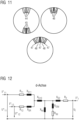
- the representation according to FIG 11 schematically shows the possible arrangements of windings in the stator of a multi-winding system generator.
- the LV windings can be arranged in sections in adjacent slots 44, and the MV windings can be arranged in sections in adjacent slots 45.
- the MV windings and the LV windings can be arranged in common slots 46.
- the MV windings and the LV windings can be arranged alternately in slots 24 and 48.
- the representation according to FIG 12 shows an equivalent circuit diagram for a D-axis of a multi-winding system generator.
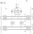
- the representation according to FIG 13 shows an eighth circuit diagram for an energy supply system 100, wherein it is shown how the first DC voltage bus 11 can be fed by the generator 6 via two different sections 61 and 64 and how the second DC voltage bus 12 can also be fed by this generator 6 via two different sections there too.
- the representation according to FIG 14 shows how two sections 61 and 62 of the first DC bus 11 in different zones 31 and 32 can be fed by a generator in one zone (generator 5 in zone 31 and generator 6 in zone 32) and how this also applies to the second DC bus 12.
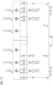
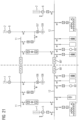
- the representation according to FIG 15 is divided into two sub-figures 15A and 15B. Both combine an energy supply system 100, which has four diesel generators 1, 2, 3, and 4 as part of the energy sources 21, 22, 23, and 24, and expresses that the energy supply system can be expanded or modified almost arbitrarily according to the requirements of the waterborne facility. Because the waterborne facility is located, for example, on a ship or an oil rig, it is operated entirely or predominantly as an island network.
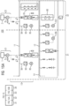
- the representation according to Figure 24 shows a ship with three zones 31, 32, and 33.
- each of the generators 5 is driven by an internal combustion engine 1, e.g., a diesel engine.
- a propulsion unit in the form of a variable-pitch propeller 108 is mechanically coupled to the traction motor 106.
- a mechanical transmission can also be connected between a generator 5 and the internal combustion engine 1 driving it, as well as between the variable-pitch propeller 108 and the traction motor 106 driving it, although this is not shown.
- a non-variable propeller can also be used.
- each of the generators 6 is driven by an internal combustion engine 2, e.g., a diesel engine.
- a propulsion unit is connected to the traction motor 107.
- a mechanical transmission can also be connected between a generator 6 and the internal combustion engine 2 that drives it, as well as between the variable-pitch propeller 109 and the drive motor 107 that drives it, although this is not shown.
- a fixed-pitch propeller can also be used.
- the traction motors 106 and 107 are ship propulsion motors, which are designed in particular as medium-voltage motors.
- the traction motor 106 is operated without an intermediate converter using the voltage generated by the generators 5 with variable amplitude and variable frequency, which constitutes the electrical shaft.
- the rotational frequency of the traction motor 106 depends on its number of pole pairs.
- the control and/or regulation of the speed of the traction motor 106 and thus of the variable-pitch propeller 108 is thus carried out indirectly by the control and/or regulation of the internal combustion engines 1 for driving the generators 5.
- a rotary movement of the internal combustion engine 1 or the generators 5 thus causes a correspondingly proportional rotary movement of the traction motor 106.
- the function of a mechanical shaft is thus simulated with the aid of electrical machines.
- the traction motor 107 is operated without an intermediate converter using the voltage generated by the generators 6 with variable amplitude and variable frequency, which constitutes the electrical shaft.
- the rotational frequency of the traction motor 106 depends on its number of pole pairs.
- the control and/or regulation of the speed of the traction motor 107 and thus of the variable-pitch propeller 109 is thus carried out indirectly by the control and/or regulation of the internal combustion engines 2 for driving the generators 6.
- a rotational movement of the internal combustion engine 2 or the generators 6 thus causes a correspondingly proportional rotational movement of the traction motor. 107.
- the function of a mechanical shaft is thus simulated with the help of electrical machines.
- variable-amplitude, variable-frequency voltage generated by the generators of an electric drive shaft is used to power an additional on-board power system converter 115, 116, which converts this variable voltage into a DC voltage for an LV DC bus 117 for the on-board power system.
- the on-board power system includes another internal combustion engine 3 and a generator 7 associated with it, whose output AC voltage can be converted into the LV DC voltage via a rectifier 118.
Landscapes
- Engineering & Computer Science (AREA)
- Chemical & Material Sciences (AREA)
- Combustion & Propulsion (AREA)
- Mechanical Engineering (AREA)
- Ocean & Marine Engineering (AREA)
- Power Engineering (AREA)
- Control Of Eletrric Generators (AREA)
- Direct Current Feeding And Distribution (AREA)
- Water Treatment By Electricity Or Magnetism (AREA)
Claims (13)
- Système (100) d'alimentation en énergie électrique pour une installation (101) hydraulique, comprenant un arbre (120, 121) électrique, dans lequel l'arbre (120, 121) électrique peut être connecté à un premier bus (11) à tension continue pour une première tension continue et à un deuxième bus (12) à tension continue pour une deuxième tension continue, dans lequel l'arbre (120, 121) électrique a au moins un générateur à vitesse de rotation variable entraîné par une machine à combustion interne pour la production d'une tension de moteur d'amplitude variable et de fréquence variable et au moins un moteur d'entraînement à vitesse de rotation variable alimenté par cette tension de moteur et accouplé à une unité de propulsion, dans lequel le premier bus (11) à tension continue est prévu pour une première tension continue et le deuxième bus (12) à tension continue est prévu pour une deuxième tension continue, dans lequel la première tension continue est plus haute que la deuxième tension continue, caractérisé par un couplage entre le premier bus (11) à tension continue et le deuxième bus (12) à tension continue pour le transport d'énergie électrique du deuxième bus à tension continue à la tension plus basse au premier bus à tension continue à la tension plus haute, afin d'alimenter l'arbre (120, 121) électrique en énergie électrique.
- Système (100) d'alimentation en énergie électrique pour une installation (101) hydraulique suivant la revendication 1, dans lequel il est prévu un régulateur tension continue/tension continue comme couplage.
- Système (100) d'alimentation en énergie électrique pour une installation (101) hydraulique suivant la revendication 1, dans lequel le régulateur tension continue/tension continue est un régulateur tension continue/tension continue bidirectionnel.
- Système (100) d'alimentation en énergie électrique pour une installation (101) hydraulique suivant l'une des revendications précédentes, dans lequel l'installation (101) hydraulique a une première zone (31) et une deuxième zone (32),comprenant une première source (21) d'énergie etune deuxième source (22) d'énergie,dans lequel la première source (21) d'énergie est prévue dans la première zone (31) pour l'alimentation d'au moins un bus (11, 12) à tension continue parmi les au moins deux bus (11, 12) à tension continue, etdans lequel la deuxième source (22) d'énergie est prévue dans la deuxième zone (32) pour l'alimentation d'au moins un bus (11, 12) à tension continue parmi les au moins deux bus (11, 12) à tension continue, dans lequel le système (100) d'alimentation en énergie électrique est subdivisé au moins en partie en fonction des zones.
- Système (100) d'alimentation en énergie électrique suivant l'une des revendications précédentes, dans lequel l'un des bus (11, 12) à tension continue peut être constitué en bus annulaire.
- Système (100) d'alimentation en énergie électrique suivant l'une des revendications précédentes, dans lequel au moins l'un des bus (11, 12) à tension continue est prévu pour s'étendre sur au moins deux zones (31, 32).
- Système (100) d'alimentation en énergie électrique suivant l'une des revendications précédentes, dans lequel au moins l'un des bus (11, 12) à tension continue a des tronçons (61, 62, 63, 64, 65, 66, 67), dans lequel les tronçons sont rapportés aux zones, dans lequel, en particulier le système d'alimentation en énergie électrique est subdivisé par les tronçons (61, 62, 63, 64, 65, 66, 67).
- Système (100) d'alimentation en énergie électrique suivant l'une des revendications précédentes,
dans lequel la première source (21) d'énergie est prévue dans la première zone (31) pour l'alimentation du premier bus (11, 12) à tension continue et du deuxième bus (12) à tension continue. - Système (100) d'alimentation en énergie électrique suivant l'une des revendications 1 à 8,
dans lequel des arbres électriques différents se trouvent dans des zones (31, 32, 33, 34) différentes. - Système (100) d'alimentation en énergie électrique suivant l'une des revendications 1 à 9, dans lequel la machine à combustion interne est une turbine à gaz.
- Procédé pour faire fonctionner un système d'alimentation en énergie électrique d'une installation (101) hydraulique suivant l'une des revendications 1 à 10,
dans lequel on transporte de l'énergie électrique d'un bus à tension continue de tension plus basse à un bus à tension continue de tension plus haute pour alimenter au moins un arbre (120, 121) en énergie électrique. - Procédé suivant la revendication 11,dans lequel l'installation (101) hydraulique a une première zone (31) et une deuxième zone (32),dans lequel l'installation (101) hydraulique a un premier bus (11) à tension continue pour une première tension continue et un deuxième bus (12) à tension continue pour une deuxième tension continue,dans lequel l'installation (101) hydraulique a une première source (21) d'énergie et une deuxième source (22),dans lequel on transfère de l'énergie électrique de la première zone (31) à la deuxième zone (32) ou de la deuxième zone (32) à la première zone (31).
- Procédé suivant la revendication 11 ou 12, dans lequel on utilise un système (100) d'alimentation en énergie suivant l'une des revendications 1 à 10.
Applications Claiming Priority (2)
| Application Number | Priority Date | Filing Date | Title |
|---|---|---|---|
| DE102018219711.3A DE102018219711A1 (de) | 2018-11-16 | 2018-11-16 | Energieversorgungssystem für eine wassergebundene Einrichtung |
| PCT/EP2019/081489 WO2020099636A1 (fr) | 2018-11-16 | 2019-11-15 | Système de distribution électrique pour une installation hydraulique |
Publications (3)
| Publication Number | Publication Date |
|---|---|
| EP3853960A1 EP3853960A1 (fr) | 2021-07-28 |
| EP3853960C0 EP3853960C0 (fr) | 2025-04-23 |
| EP3853960B1 true EP3853960B1 (fr) | 2025-04-23 |
Family
ID=68731946
Family Applications (1)
| Application Number | Title | Priority Date | Filing Date |
|---|---|---|---|
| EP19812706.0A Active EP3853960B1 (fr) | 2018-11-16 | 2019-11-15 | Système de distribution électrique pour une installation hydraulique |
Country Status (6)
| Country | Link |
|---|---|
| US (1) | US11787522B2 (fr) |
| EP (1) | EP3853960B1 (fr) |
| CN (1) | CN113056853B (fr) |
| DE (1) | DE102018219711A1 (fr) |
| ES (1) | ES3032761T3 (fr) |
| WO (1) | WO2020099636A1 (fr) |
Families Citing this family (7)
| Publication number | Priority date | Publication date | Assignee | Title |
|---|---|---|---|---|
| US12286204B2 (en) * | 2019-07-01 | 2025-04-29 | Electronic Power Design, Inc. | Hybrid power generation plant system and method |
| US11325714B2 (en) * | 2020-07-09 | 2022-05-10 | General Electric Company | Electric power system for a vehicle |
| GB202011388D0 (en) * | 2020-07-23 | 2020-09-09 | Siemens Gas And Power Gmbh & Co Kg | Energy distribution system |
| DE102021116418A1 (de) * | 2021-06-24 | 2022-12-29 | Sma Solar Technology Ag | Verfahren zum Betrieb eines Energieversorgungssystems, Vorrichtung zum Austausch elektrischer Leistung in einem Energieversorgungssystem und Energieversorgungssystem |
| JP7056894B1 (ja) | 2021-12-08 | 2022-04-19 | 真士 加藤 | 船舶 |
| EP4274046B1 (fr) * | 2022-05-04 | 2024-11-13 | ABB E-mobility B.V. | Système de distribution cc et procédé de distribution d'énergie |
| DE102024209978A1 (de) * | 2024-10-15 | 2026-04-16 | Siemens Energy Global GmbH & Co. KG | Stromversorgung von Wasserfahrzeugen |
Family Cites Families (14)
| Publication number | Priority date | Publication date | Assignee | Title |
|---|---|---|---|---|
| US5903116A (en) * | 1997-09-08 | 1999-05-11 | Capstone Turbine Corporation | Turbogenerator/motor controller |
| AU2003299537A1 (en) | 2002-09-18 | 2004-06-07 | Sure Power Corporation | Dc power system for marine vessels |
| DE102009043530A1 (de) | 2009-09-30 | 2011-04-07 | Siemens Aktiengesellschaft | Elektrische Antriebswelle und Fahrzeug mit einer derartigen elektrischen Antriebswelle |
| AU2011209476B2 (en) | 2010-02-01 | 2013-09-05 | Siemens Energy Global GmbH & Co. KG | Ship drive system having a plurality of electric drive shafts |
| CN101917013B (zh) * | 2010-08-10 | 2012-07-04 | 华中科技大学 | 带储能的双馈风力发电系统 |
| CN102557161B (zh) * | 2011-12-30 | 2013-04-03 | 清华大学 | 一种基于人工造流技术的船载水华抑制装置 |
| EP4071995A1 (fr) | 2012-07-06 | 2022-10-12 | GE Energy Power Conversion Technology Ltd. | Systèmes de distribution de puissance |
| CN103047075B (zh) * | 2013-01-08 | 2014-12-24 | 浙江大学 | 海流能发电装置及其控制方法 |
| EP2949571A1 (fr) | 2014-05-30 | 2015-12-02 | Siemens Aktiengesellschaft | Système de propulsion pour un bateau et son fonctionnement |
| CN104333033A (zh) | 2014-11-25 | 2015-02-04 | 国网吉林省电力有限公司延边供电公司 | 一种配电系统和配电方法 |
| EP3035477A1 (fr) * | 2014-12-19 | 2016-06-22 | ABB Technology Ltd | Système d'alimentation comprenant un système de stockage d'énergie central et procédé de commande de transfert de puissance dans un système de puissance |
| EP3046206B1 (fr) | 2015-01-15 | 2018-10-31 | Siemens Aktiengesellschaft | Distribution de puissance sur un vaisseau |
| CN107210621A (zh) | 2015-01-23 | 2017-09-26 | 西门子股份公司 | 船舶上的电能的分配 |
| EP3109964A1 (fr) * | 2015-06-26 | 2016-12-28 | Siemens Aktiengesellschaft | Grille cc |
-
2018
- 2018-11-16 DE DE102018219711.3A patent/DE102018219711A1/de not_active Withdrawn
-
2019
- 2019-11-15 US US17/290,922 patent/US11787522B2/en active Active
- 2019-11-15 ES ES19812706T patent/ES3032761T3/es active Active
- 2019-11-15 EP EP19812706.0A patent/EP3853960B1/fr active Active
- 2019-11-15 CN CN201980075661.1A patent/CN113056853B/zh active Active
- 2019-11-15 WO PCT/EP2019/081489 patent/WO2020099636A1/fr not_active Ceased
Also Published As
| Publication number | Publication date |
|---|---|
| ES3032761T3 (en) | 2025-07-24 |
| EP3853960C0 (fr) | 2025-04-23 |
| US11787522B2 (en) | 2023-10-17 |
| DE102018219711A1 (de) | 2020-05-20 |
| US20210403135A1 (en) | 2021-12-30 |
| EP3853960A1 (fr) | 2021-07-28 |
| CN113056853B (zh) | 2024-01-23 |
| CN113056853A (zh) | 2021-06-29 |
| WO2020099636A1 (fr) | 2020-05-22 |
Similar Documents
| Publication | Publication Date | Title |
|---|---|---|
| EP3853960B1 (fr) | Système de distribution électrique pour une installation hydraulique | |
| EP2483146B1 (fr) | Arbre d'entraînement électrique et véhicule doté d'un tel arbre d'entraînement électrique | |
| EP3213952B1 (fr) | Systeme d'entrainement electrique pour un aeronef et procede de fonctionnement | |
| EP2013077B1 (fr) | Procédé de fonctionnement d'un système de commande de navire avec récupération de chaleur et système de commande de navire avec récupération de chaleur | |
| EP2531366B1 (fr) | Système de propulsion de bateau comprenant plusieurs arbres d'entraînement électriques | |
| EP1537017B1 (fr) | Systeme d'equipement pour bateau de type "fregate" | |
| EP3837750B1 (fr) | Système d'alimentation électrique conçu pour un dispositif hydraulique comportant un premier et un deuxième système d'enroulement d'un système de générateur pour alimenter différents bus à tension continue | |
| EP1701879A2 (fr) | Systeme de production d'energie, de repartition et d'alimentation en courant de bord pour des navires de surface de marine de differentes classes et tailles a faibles rejets | |
| WO2020064996A1 (fr) | Système d'alimentation électrique conçu pour un dispositif maritime comportant différentes zones reliées | |
| EP1960260A1 (fr) | Systeme d'entrainement hybride pour navire | |
| DE102008043626A1 (de) | Leistungsverteilungs-Vorrichtung zum Verteilen von Leistung und Verfahren zum Verteilen von Leistung | |
| DE102010003632B4 (de) | Vorrichtung und Verfahren zum Wandeln bereitgestellter elektrischer Leistung in mechanische Leistung zum Starten zumindest eines Triebwerkes | |
| DE102005056700A1 (de) | Verfahren zum Versorgen von elektrischen Schiffs-Bordnetzen mit Fremdenergie | |
| WO2020070201A1 (fr) | Système d'alimentation électrique conçu pour un dispositif hydraulique comportant un convertisseur multiniveau modulaire | |
| EP1894836A2 (fr) | Navire doté d'un entraînement électrique et entraînement auxiliaire de moteurs à combustion interne | |
| EP3837748B1 (fr) | Dispositif maritime comportant plusieurs zones comprenant un système d'alimentation électrique | |
| DE19522302C2 (de) | Schiffsantriebsanlage | |
| EP0982828A2 (fr) | Méthode et dispositif de compensation de la puissance réactive dans des réseaux embarqués | |
| DE2237400A1 (de) | Antriebs- und stromversorgungsanlage fuer schiffe | |
| DE3836418A1 (de) | Energieversorgungsanlage fuer dieselmotorschiffe mit festpropeller | |
| DE102015201477B4 (de) | Aggregat zur Stromerzeugung, Stromnetz mit einem solchen Aggregat, Kraftfahrzeug mit einem solchen Stromnetz oder Aggregat, und Verfahren zum Betreiben eines solchen Aggregats zur Stromerzeugung | |
| DE29823849U1 (de) | Vorrichtung zur Blindleistungskompensation in Bordnetzen |
Legal Events
| Date | Code | Title | Description |
|---|---|---|---|
| STAA | Information on the status of an ep patent application or granted ep patent |
Free format text: STATUS: UNKNOWN |
|
| STAA | Information on the status of an ep patent application or granted ep patent |
Free format text: STATUS: THE INTERNATIONAL PUBLICATION HAS BEEN MADE |
|
| PUAI | Public reference made under article 153(3) epc to a published international application that has entered the european phase |
Free format text: ORIGINAL CODE: 0009012 |
|
| STAA | Information on the status of an ep patent application or granted ep patent |
Free format text: STATUS: REQUEST FOR EXAMINATION WAS MADE |
|
| 17P | Request for examination filed |
Effective date: 20210421 |
|
| AK | Designated contracting states |
Kind code of ref document: A1 Designated state(s): AL AT BE BG CH CY CZ DE DK EE ES FI FR GB GR HR HU IE IS IT LI LT LU LV MC MK MT NL NO PL PT RO RS SE SI SK SM TR |
|
| DAV | Request for validation of the european patent (deleted) | ||
| DAX | Request for extension of the european patent (deleted) | ||
| GRAP | Despatch of communication of intention to grant a patent |
Free format text: ORIGINAL CODE: EPIDOSNIGR1 |
|
| STAA | Information on the status of an ep patent application or granted ep patent |
Free format text: STATUS: GRANT OF PATENT IS INTENDED |
|
| INTG | Intention to grant announced |
Effective date: 20241206 |
|
| GRAS | Grant fee paid |
Free format text: ORIGINAL CODE: EPIDOSNIGR3 |
|
| GRAA | (expected) grant |
Free format text: ORIGINAL CODE: 0009210 |
|
| STAA | Information on the status of an ep patent application or granted ep patent |
Free format text: STATUS: THE PATENT HAS BEEN GRANTED |
|
| AK | Designated contracting states |
Kind code of ref document: B1 Designated state(s): AL AT BE BG CH CY CZ DE DK EE ES FI FR GB GR HR HU IE IS IT LI LT LU LV MC MK MT NL NO PL PT RO RS SE SI SK SM TR |
|
| REG | Reference to a national code |
Ref country code: GB Ref legal event code: FG4D Free format text: NOT ENGLISH |
|
| REG | Reference to a national code |
Ref country code: CH Ref legal event code: EP |
|
| REG | Reference to a national code |
Ref country code: IE Ref legal event code: FG4D Free format text: LANGUAGE OF EP DOCUMENT: GERMAN |
|
| U01 | Request for unitary effect filed |
Effective date: 20250423 |
|
| U07 | Unitary effect registered |
Designated state(s): AT BE BG DE DK EE FI FR IT LT LU LV MT NL PT RO SE SI Effective date: 20250428 |
|
| REG | Reference to a national code |
Ref country code: ES Ref legal event code: FG2A Ref document number: 3032761 Country of ref document: ES Kind code of ref document: T3 Effective date: 20250724 |
|
| PG25 | Lapsed in a contracting state [announced via postgrant information from national office to epo] |
Ref country code: GR Free format text: LAPSE BECAUSE OF FAILURE TO SUBMIT A TRANSLATION OF THE DESCRIPTION OR TO PAY THE FEE WITHIN THE PRESCRIBED TIME-LIMIT Effective date: 20250724 |
|
| PG25 | Lapsed in a contracting state [announced via postgrant information from national office to epo] |
Ref country code: PL Free format text: LAPSE BECAUSE OF FAILURE TO SUBMIT A TRANSLATION OF THE DESCRIPTION OR TO PAY THE FEE WITHIN THE PRESCRIBED TIME-LIMIT Effective date: 20250423 |
|
| PG25 | Lapsed in a contracting state [announced via postgrant information from national office to epo] |
Ref country code: HR Free format text: LAPSE BECAUSE OF FAILURE TO SUBMIT A TRANSLATION OF THE DESCRIPTION OR TO PAY THE FEE WITHIN THE PRESCRIBED TIME-LIMIT Effective date: 20250423 |
|
| PG25 | Lapsed in a contracting state [announced via postgrant information from national office to epo] |
Ref country code: RS Free format text: LAPSE BECAUSE OF FAILURE TO SUBMIT A TRANSLATION OF THE DESCRIPTION OR TO PAY THE FEE WITHIN THE PRESCRIBED TIME-LIMIT Effective date: 20250723 |
|
| PG25 | Lapsed in a contracting state [announced via postgrant information from national office to epo] |
Ref country code: IS Free format text: LAPSE BECAUSE OF FAILURE TO SUBMIT A TRANSLATION OF THE DESCRIPTION OR TO PAY THE FEE WITHIN THE PRESCRIBED TIME-LIMIT Effective date: 20250823 |
|
| U20 | Renewal fee for the european patent with unitary effect paid |
Year of fee payment: 7 Effective date: 20251126 |
|
| PGFP | Annual fee paid to national office [announced via postgrant information from national office to epo] |
Ref country code: NO Payment date: 20251124 Year of fee payment: 7 |
|
| PG25 | Lapsed in a contracting state [announced via postgrant information from national office to epo] |
Ref country code: SM Free format text: LAPSE BECAUSE OF FAILURE TO SUBMIT A TRANSLATION OF THE DESCRIPTION OR TO PAY THE FEE WITHIN THE PRESCRIBED TIME-LIMIT Effective date: 20250423 |
|
| PG25 | Lapsed in a contracting state [announced via postgrant information from national office to epo] |
Ref country code: CZ Free format text: LAPSE BECAUSE OF FAILURE TO SUBMIT A TRANSLATION OF THE DESCRIPTION OR TO PAY THE FEE WITHIN THE PRESCRIBED TIME-LIMIT Effective date: 20250423 |
|
| PG25 | Lapsed in a contracting state [announced via postgrant information from national office to epo] |
Ref country code: SK Free format text: LAPSE BECAUSE OF FAILURE TO SUBMIT A TRANSLATION OF THE DESCRIPTION OR TO PAY THE FEE WITHIN THE PRESCRIBED TIME-LIMIT Effective date: 20250423 |
|
| PGFP | Annual fee paid to national office [announced via postgrant information from national office to epo] |
Ref country code: ES Payment date: 20251209 Year of fee payment: 7 |
|
| PLBE | No opposition filed within time limit |
Free format text: ORIGINAL CODE: 0009261 |
|
| STAA | Information on the status of an ep patent application or granted ep patent |
Free format text: STATUS: NO OPPOSITION FILED WITHIN TIME LIMIT |
|
| REG | Reference to a national code |
Ref country code: CH Ref legal event code: L10 Free format text: ST27 STATUS EVENT CODE: U-0-0-L10-L00 (AS PROVIDED BY THE NATIONAL OFFICE) Effective date: 20260304 |
|
| 26N | No opposition filed |
Effective date: 20260126 |