EP3853981B1 - Hilfseinheit für ein kraftfahrzeug - Google Patents
Hilfseinheit für ein kraftfahrzeug Download PDFInfo
- Publication number
- EP3853981B1 EP3853981B1 EP18772788.8A EP18772788A EP3853981B1 EP 3853981 B1 EP3853981 B1 EP 3853981B1 EP 18772788 A EP18772788 A EP 18772788A EP 3853981 B1 EP3853981 B1 EP 3853981B1
- Authority
- EP
- European Patent Office
- Prior art keywords
- stator body
- contact
- motor
- motor vehicle
- auxiliary unit
- Prior art date
- Legal status (The legal status is an assumption and is not a legal conclusion. Google has not performed a legal analysis and makes no representation as to the accuracy of the status listed.)
- Active
Links
Images


Classifications
-
- H—ELECTRICITY
- H02—GENERATION; CONVERSION OR DISTRIBUTION OF ELECTRIC POWER
- H02K—DYNAMO-ELECTRIC MACHINES
- H02K11/00—Structural association of dynamo-electric machines with electric components or with devices for shielding, monitoring or protection
- H02K11/40—Structural association with grounding devices
-
- H—ELECTRICITY
- H02—GENERATION; CONVERSION OR DISTRIBUTION OF ELECTRIC POWER
- H02K—DYNAMO-ELECTRIC MACHINES
- H02K5/00—Casings; Enclosures; Supports
- H02K5/04—Casings or enclosures characterised by the shape, form or construction thereof
- H02K5/22—Auxiliary parts of casings not covered by groups H02K5/06-H02K5/20, e.g. shaped to form connection boxes or terminal boxes
- H02K5/225—Terminal boxes or connection arrangements
-
- H—ELECTRICITY
- H02—GENERATION; CONVERSION OR DISTRIBUTION OF ELECTRIC POWER
- H02K—DYNAMO-ELECTRIC MACHINES
- H02K1/00—Details of the magnetic circuit
- H02K1/06—Details of the magnetic circuit characterised by the shape, form or construction
- H02K1/12—Stationary parts of the magnetic circuit
- H02K1/14—Stator cores with salient poles
- H02K1/141—Stator cores with salient poles consisting of C-shaped cores
- H02K1/143—Stator cores with salient poles consisting of C-shaped cores of the horse-shoe type
-
- H—ELECTRICITY
- H02—GENERATION; CONVERSION OR DISTRIBUTION OF ELECTRIC POWER
- H02K—DYNAMO-ELECTRIC MACHINES
- H02K11/00—Structural association of dynamo-electric machines with electric components or with devices for shielding, monitoring or protection
- H02K11/30—Structural association with control circuits or drive circuits
- H02K11/33—Drive circuits, e.g. power electronics
Definitions
- the invention is directed to a motor vehicle auxiliary unit, for example to an electric gas pump for pumping fuel vapor out of a motor vehicle fuel tank.
- Such a motor vehicle auxiliary unit comprises an electronically commutated electric motor with a permanent magnetic motor rotor, with a motor stator with a ferromagnetic stator body and at least one stator coil, as well as with a motor electronics with a ground terminal for electrically connecting the motor electronics with an external vehicle ground potential.
- the motor vehicle auxiliary unit also comprises a unit connector plug for externally energizing and, optionally, for controlling the motor vehicle auxiliary unit.
- the unit connector plug comprises at least an external-ground connector lug for electrically connecting the motor vehicle auxiliary unit with an external vehicle ground potential.
- the external-ground connector lug is internally directly connected with the motor electronics ground terminal for electrically connecting the motor electronics ground terminal with the external vehicle ground potential.
- the electronically commutated electric motor of the motor vehicle auxiliary unit generates electromagnetic interference radiation, which can cause malfunctions or even failure of other electronic devices in the vicinity of the electric motor.
- the interference radiation can, for example, interfere with the motor electronics of the electric motor.
- electronic devices have to fulfill application-specific electromagnetic compatibility (EMC) directives.
- EMC electromagnetic compatibility
- the electric motor is provided with a stator body contact element providing a direct electric connection between the motor electronics ground terminal and the stator body to minimize the electromagnetic interference radiation being generated by the electric motor.
- An electric motor with a stator body contact element electrically connecting the stator body with the motor electronics is, for example, disclosed in EP 3 007 330 B1 .
- the stator body contact element is fixed to the stator body with one axial end and is plugged into a motor electronics ground terminal with the opposite axial end.
- the stator body contact element has to be exactly positioned and aligned during the assembling process to fit into the corresponding motor electronics terminal.
- EP 3 340 444 A2 discloses a radiator fan module with an electric motor and with a connector cable.
- the radiator fan module comprises a punched-grid connection element for connecting wires of the connector cable with a printed circuit board.
- the punched-grid connection element comprises a stator body contact element which provides an electric connection between an external-ground wire of the connector cable and a stator body of the electric motor.
- EP 2 500 576 A1 discloses a heating system circulator pump with an electric motor and with a connector plug.
- the connector plug comprises an external-ground connector lug which is directly electrically connected with a ground terminal of a circuit board.
- the external-ground connector lug comprises a housing contact element which provides a direct electric connection with a housing of the electric motor.
- the electric motor of the motor vehicle auxiliary unit is also provided with a motor electronics being electrically connected with the stator coil for energizing the stator coil and thereby driving the motor rotor.
- the motor electronics comprises several power semiconductors for commutating the electric drive energy being provided to the stator coil.
- the motor electronics also comprises a ground terminal for electrically connecting the motor electronics with an external vehicle ground potential to provide the motor electronics with electric energy.
- the motor vehicle auxiliary unit is also provided with a unit connector plug for externally energizing and controlling the motor vehicle auxiliary unit.
- the unit connector plug comprises at least an external-ground connector lug for electrically connecting the motor vehicle auxiliary unit with an external vehicle ground potential.
- the external-ground connector lug is made of a metal and provides a direct low-resistive electric connection with the motor electronics ground terminal. All connector lugs of the unit connector plug are typically simultaneously stamped out of a metal sheet and are post-processed by a mechanical deformation process.
- the external-ground connector lug is provided with an integral stator body contact element providing a direct electric connection with the stator body.
- the external-ground connector lug is provided as a single-piece three-way electric connector providing a direct electric interconnection between an external contact pin being electrically connectable with the vehicle ground potential, the motor electronics and the stator body.
- the stator body contact element extends from the external contact pin to the stator body and is reliably fixed to the stator body, for example by overmolding.
- the electric connection with the motor electronics is provided by an integral motor electronics contact element which extends from the external contact pin to the motor electronics and typically is plugged into a correspondingly shaped ground terminal of the motor electronics.
- stator body contact element is integrated into the unit connector plug, no additional contact element is required, which has to be separately mounted and aligned.
- the motor vehicle auxiliary unit according to the invention can be assembled in a simple way.
- the integral contact element also reduces the number of junctions in the electric connection between the stator body and the vehicle ground potential and, as a result, reduces the total electric resistance of this electric connection.
- the direct electric connection between the stator body, the motor electronics ground terminal and the external-ground potential ensures good EMC characteristics of the motor vehicle auxiliary unit according to the invention.
- a transversal stator body top side is provided with an axial contact opening, wherein the stator body contact element is plugged into the contact opening.
- the stator body is provided with an electrically isolating protection coating.
- the stator body contact element is preferably provided with at least one cutting element penetrating the isolating stator body coating to provide an electric contact with the stator body.
- the cutting element also fixes the external-ground connector lug to the stator body.
- the contact ring is provided with an axially extending plug cylinder and with a support flange laterally projecting from the plug cylinder.
- the plug cylinder is plugged into the contact opening and radially contacts the inside surface of the contact opening.
- the support flange is in axial contact with the stator body top side to define the intrusion depth of the plug cylinder into the contact opening. This provides a simple and reliable positioning of the external-ground connector lug with respect to the stator body.
- the outside diameter of the plug cylinder is slightly larger than the opening diameter of the contact opening.
- the term "opening diameter” always means the diameter of the unstressed contact opening, i.e. the diameter of the contact opening before the stator body contact element is plugged into the contact opening. Since the plug cylinder outside diameter is slightly larger than the opening diameter of the contact opening, the plug cylinder abrades the isolation from the inside surface of the contact opening when being pressed into the contact opening. As a result, the plug cylinder provides a reliable electric contact with the stator body as well as a robust fixation of the external-ground connector lug to the stator body.
- the contact ring is provided with several cutting elements which are distributed along the outside circumference of the contact ring and which axially protrude over the contact ring bottom side.
- the cutting elements penetrate the stator body isolation coating if the contact ring is pressed against the stator body top side.
- the penetrating cutting elements provide a reliable electric connection and avoid a lateral shifting of the stator body contact element with respect to the stator body.
- a separate fastening means is provided which extends through the contact ring into the contact opening and axially presses the contact ring against the stator body top side.
- the fastening means is provided with an axially extending pin and a laterally extending head.
- the pin axially extends through the contact ring into the contact opening to fix the fastening means within or at the stator body in that way that the head axially presses the contact ring against the stator body.
- the fastening means can, for example, be a rivet or a screw.
- the fastening means provides a robust fixation of the external-ground connector lug.
- the axial pressure generated by the fastening means also provides a reliable electric contact with the stator body, in particular if the stator body contact element is provided with cutting elements.
- the unit connector plug also comprises a power connector lug being electrically connected with the motor electronics for energizing the motor electronics so that no additional connector plug is required for energizing the motor electronics.
- the motor vehicle auxiliary unit is provided with a sensor element and the unit connector plug comprises at least one sensor connector lug being electrically connected with the sensor element.
- the sensor element can, for example, be a pressure sensor or a speed sensor being externally readable/programmable via the sensor connector lug of the unit connector plug. As a result, no additional sensor connector plug is required.
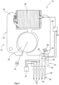
- the electric motor 12 comprises a rotatable permanent magnetic motor rotor 20 and a static motor stator 22 with a ferromagnetic stator body 24 and a single stator coil 26.
- the motor rotor 20 is co-rotatably connected with the pump wheel 14.
- the stator body 24 is a laminated stator body which is coated with an electrically isolating protection coating 27.
- the stator body 24 is provided with an axial contact opening 46 which in the present embodiment of the invention is provided with a circular cross section and which extends from a stator body top side 48 along the entire axial height of the stator body 24 to a stator body bottom side 50.
- the electric motor 12 also comprises a motor electronics 28 being electrically connected to the stator coil 26 for energizing the stator coil 26 for driving the motor rotor 20 and, as a result, for driving the pump wheel 14.
- the unit connector plug 18 comprises a plug housing 30 and is provided with three sensor connector lugs 32, a power connector lug 34 and an external-ground connector lug 36, which are externally electrically contactable. All connector lugs 32,34,36 are stamped out of a single metal sheet and post-processed by a mechanical deformation process.
- the sensor connector lugs 32 are internally electrically connected with the sensor element 16 for energizing the sensor element 16 and/or for providing a data interface for reading/writing data from/to the sensor element 16.
- the power connector lug 34 is internally electrically connected with the motor electronics 28 and externally connectable to an external energy source, for example to a motor vehicle battery, for providing the motor electronics 28 with electric energy.
- the external-ground connector lug 36 is provided as a single-piece three-way electric connector comprising an external-ground pin 38, a motor electronics contact element 40 and a stator body contact element 42.
- the external-ground pin 38 is externally connectable to an external motor vehicle ground potential.
- the motor electronics contact element 40 provides a direct electric connection with the motor electronics 28, in particular with a ground terminal 44 of the motor electronics 28.
- the stator body contact element 42 provides a direct electric contact with the stator body 24.
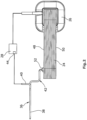
- the stator body contact element 42 is provided with a substantially laterally extending support bar 52 and with an arrowhead-shaped cutting element 54.
- the stator body contact element 42 is plugged into the contact opening 46 in that way that the support bar 52 is in axial contact with the stator body top side 48 and that the cutting element 54 intrudes into the contact opening 46.
- the lateral width of the cutting element 54 is slightly larger than the opening diameter of the contact opening 46 so that the cutting element 54 cuts into the sidewalls of the contact opening 46.
- the cutting element 54 cuts through the isolation coating 27 of the stator body 24 so that the cutting element 54 provides a reliable electric contact with the stator body 24.
- the cutting element 54 also reliably positions the stator body contact element 42 with respect to the stator body 24 during the assembling process.
- the stator body contact element 42" is fastened to the stator body 24 by a separate fastening means 62 which in the present embodiment of the invention is a screw with a transversal screw head 64 and an axially extending screw pin 66.
- the screw head 64 is in axial contact with the top side of the contact ring 56".
- the screw pin 66 axially extends from the screw head 64 through the contact hole 46 and is threaded into a corresponding nut 68 being located at the bottom side of the stator body 24.
Landscapes
- Engineering & Computer Science (AREA)
- Power Engineering (AREA)
- Motor Or Generator Frames (AREA)
Claims (11)
- Kraftfahrzeughilfsaggregat (10), umfassend- einen elektronisch kommutierten Elektromotor (12) mit• einem permanentmagnetischen Motorrotor (20)• einem Motorstator (22) mit einem ferromagnetischen Statorkörper (24) und mindestens einer Statorspule (26), und• einer Motorelektronik (28) mit einem Masseanschluss (44), und- einen Aggregatanschlussstecker (18) mit zumindest einer Außenmasseanschlussfahne (36), die mit dem Motorelektronikmasseanschluss (44) direkt elektrisch verbunden ist,- wobei die Außenmasseanschlussfahne (36) ein integriertes Statorkörperkontaktelement (42; 42'; 42") aufweist, das sich zu dem Statorkörper (24) erstreckt und eine direkte elektrische Verbindung mit dem Statorkörper (24) herstellt.
- Kraftfahrzeughilfsaggregat (10) nach Anspruch 1, wobei eine quer verlaufende Statorkörperoberseite (48) eine axiale Kontaktöffnung (46) aufweist, und
wobei das Statorkörperkontaktelement (42; 42') in die Kontaktöffnung (46) gesteckt ist. - Kraftfahrzeughilfsaggregat (10) nach einem der vorhergehenden Ansprüche, wobei der Statorkörper (24) eine elektrisch isolierende Beschichtung (27) aufweist, und
wobei das Statorkörperkontaktelement (42; 42") mindestens ein Schneidelement (54; 54") aufweist, das die Statorkörperbeschichtung (27) durchdringt. - Kraftfahrzeughilfsaggregat (10) nach Anspruch 2, wobei die Kontaktöffnung (46) im Wesentlichen kreisförmig ist, und
wobei das Statorkörperkontaktelement (42'; 42") einen Kontaktring (56; 56") umfasst. - Kraftfahrzeughilfsaggregat (10) nach Anspruch 4, wobei der Innendurchmesser des Kontaktrings (56") im Wesentlichen gleich dem Öffnungsdurchmesser der Kontaktöffnung (46) ist.
- Kraftfahrzeughilfsaggregat (10) nach Anspruch 4, wobei der Kontaktring (56) einen sich axial erstreckenden Steckzylinder (58) und einen von dem Steckzylinder (58) seitlich vorstehenden Stützflansch (60) aufweist,
wobei der Steckzylinder (58) in die Kontaktöffnung (46) gesteckt ist und radial an der Innenfläche der Kontaktöffnung (46) anliegt, und wobei der Stützflansch (60) axial an der Statorkörperoberseite (48) anliegt. - Kraftfahrzeughilfsaggregat (10) nach Anspruch 6, wobei der Außendurchmesser des Steckzylinders (58) geringfügig größer als der Öffnungsdurchmesser der Kontaktöffnung (46) ist.
- Kraftfahrzeughilfsaggregat (10) nach einem der Ansprüche 4 bis 7, wobei der Kontaktring (56") mehrere Schneidelemente (54") aufweist, die entlang des Außenumfangs des Kontaktrings (56") verteilt angeordnet sind.
- Kraftfahrzeughilfsaggregat (10) nach einem der Ansprüche 4 bis 8, wobei ein separates Befestigungsmittel (62) vorhanden ist, das sich durch den Kontaktring (56") hindurch in die Kontaktöffnung (46) hinein erstreckt und den Kontaktring (56") axial gegen die Statorkörperoberseite (48) drückt.
- Kraftfahrzeughilfsaggregat (10) nach einem der vorhergehenden Ansprüche, wobei der Aggregatstecker (18) mindestens eine Leistungsanschlussfahne (34) umfasst, die mit der Motorelektronik (28) elektrisch verbunden ist, um die Motorelektronik (28) mit Energie zu versorgen.
- Kraftfahrzeughilfsaggregat (10) nach einem der vorhergehenden Ansprüche, wobei ein Sensorelement (16) vorhanden ist, und
wobei der Geräteanschlussstecker (18) mindestens eine Sensoranschlussfahne (32) umfasst, die mit dem Sensorelement (16) elektrisch verbunden ist.
Applications Claiming Priority (1)
| Application Number | Priority Date | Filing Date | Title |
|---|---|---|---|
| PCT/EP2018/075015 WO2020057714A1 (en) | 2018-09-17 | 2018-09-17 | Motor vehicle auxiliary unit |
Publications (2)
| Publication Number | Publication Date |
|---|---|
| EP3853981A1 EP3853981A1 (de) | 2021-07-28 |
| EP3853981B1 true EP3853981B1 (de) | 2023-06-21 |
Family
ID=63637892
Family Applications (1)
| Application Number | Title | Priority Date | Filing Date |
|---|---|---|---|
| EP18772788.8A Active EP3853981B1 (de) | 2018-09-17 | 2018-09-17 | Hilfseinheit für ein kraftfahrzeug |
Country Status (2)
| Country | Link |
|---|---|
| EP (1) | EP3853981B1 (de) |
| WO (1) | WO2020057714A1 (de) |
Family Cites Families (8)
| Publication number | Priority date | Publication date | Assignee | Title |
|---|---|---|---|---|
| EP0026833B1 (de) * | 1979-09-07 | 1982-12-22 | Siemens Aktiengesellschaft | Schutzleiteranschluss für Motoren, insbesondere Aussenläufer-Kleinmotoren, und Verfahren für seine Herstellung |
| JP3543881B2 (ja) * | 1995-11-08 | 2004-07-21 | 株式会社デンソー | 交流発電機 |
| WO2004088818A1 (ja) * | 2003-03-31 | 2004-10-14 | Matsushita Electric Industrial Co., Ltd. | 信頼性の高いアース構造を有するモータ及びそのモータを搭載した電気機器 |
| PL2500576T3 (pl) * | 2011-03-12 | 2017-02-28 | Grundfos Management A/S | Pompa obiegowa do instalacji grzewczej |
| DE102012006020A1 (de) * | 2012-03-24 | 2013-09-26 | Minebea Co., Ltd. | Stator für eine elektrische Maschine |
| KR101316144B1 (ko) * | 2012-06-11 | 2013-10-08 | 뉴모텍(주) | 모터 |
| DE102014220201A1 (de) | 2014-10-06 | 2016-04-07 | Bühler Motor GmbH | Elektronisch kommutierter Gleichstrommotor, insbesondere für eine Ölpumpe |
| DE102016223844B4 (de) * | 2016-11-30 | 2022-01-27 | Brose Fahrzeugteile SE & Co. Kommanditgesellschaft, Würzburg | Elektromotor und Kühlerlüftermodul mit einem solchen Elektromotor |
-
2018
- 2018-09-17 WO PCT/EP2018/075015 patent/WO2020057714A1/en not_active Ceased
- 2018-09-17 EP EP18772788.8A patent/EP3853981B1/de active Active
Also Published As
| Publication number | Publication date |
|---|---|
| WO2020057714A1 (en) | 2020-03-26 |
| EP3853981A1 (de) | 2021-07-28 |
Similar Documents
| Publication | Publication Date | Title |
|---|---|---|
| CN110771017B (zh) | 具有壳体的电驱动单元 | |
| CN100392958C (zh) | 电驱动单元 | |
| US8979580B2 (en) | Fluid-sealing electric motor connector and motor | |
| JP4774888B2 (ja) | モータ | |
| JP6351750B2 (ja) | 制御ユニットおよびこれを用いた電動パワーステアリング装置 | |
| US20100090635A1 (en) | Pump unit | |
| CN103206374A (zh) | 电动泵 | |
| CN106660425A (zh) | 机电伺服驱动器 | |
| KR102566067B1 (ko) | 브러시 홀딩 부품 및 플러그 모듈을 포함한 전기 기계 | |
| US6479916B1 (en) | Method and apparatus for mounting electronic motor controls | |
| JP5691397B2 (ja) | 電動ポンプ | |
| CN113678346A (zh) | 具有无刷电动马达的驱动设备 | |
| JP4697597B2 (ja) | ブスバーおよびモータ | |
| CN112075016B (zh) | 电气的机动车辅助机组 | |
| JP5523044B2 (ja) | 駆動制御装置、およびモータユニット | |
| US9480143B2 (en) | Motor control device | |
| CN102056776A (zh) | 马达-传动装置-单元、尤其雨刷器马达 | |
| EP1351846B1 (de) | Motor-pumpen-aggregat, insbesondere kraftfahrzeug-bremsvorrichtung | |
| EP3853981B1 (de) | Hilfseinheit für ein kraftfahrzeug | |
| JP6736904B2 (ja) | 駆動装置 | |
| CN106411041A (zh) | 驱动单元 | |
| US6945757B2 (en) | Motor pump unit, particularly a motor vehicle braking device | |
| EP1239152B1 (de) | Elektrisch angetriebene Pumpe | |
| JP4702593B2 (ja) | モータ | |
| CN110365166B (zh) | 带有极壳体和电子器件壳体的电的驱动单元 |
Legal Events
| Date | Code | Title | Description |
|---|---|---|---|
| STAA | Information on the status of an ep patent application or granted ep patent |
Free format text: STATUS: UNKNOWN |
|
| STAA | Information on the status of an ep patent application or granted ep patent |
Free format text: STATUS: THE INTERNATIONAL PUBLICATION HAS BEEN MADE |
|
| PUAI | Public reference made under article 153(3) epc to a published international application that has entered the european phase |
Free format text: ORIGINAL CODE: 0009012 |
|
| STAA | Information on the status of an ep patent application or granted ep patent |
Free format text: STATUS: REQUEST FOR EXAMINATION WAS MADE |
|
| 17P | Request for examination filed |
Effective date: 20210408 |
|
| AK | Designated contracting states |
Kind code of ref document: A1 Designated state(s): AL AT BE BG CH CY CZ DE DK EE ES FI FR GB GR HR HU IE IS IT LI LT LU LV MC MK MT NL NO PL PT RO RS SE SI SK SM TR |
|
| DAV | Request for validation of the european patent (deleted) | ||
| DAX | Request for extension of the european patent (deleted) | ||
| GRAP | Despatch of communication of intention to grant a patent |
Free format text: ORIGINAL CODE: EPIDOSNIGR1 |
|
| STAA | Information on the status of an ep patent application or granted ep patent |
Free format text: STATUS: GRANT OF PATENT IS INTENDED |
|
| INTG | Intention to grant announced |
Effective date: 20230112 |
|
| GRAS | Grant fee paid |
Free format text: ORIGINAL CODE: EPIDOSNIGR3 |
|
| GRAA | (expected) grant |
Free format text: ORIGINAL CODE: 0009210 |
|
| STAA | Information on the status of an ep patent application or granted ep patent |
Free format text: STATUS: THE PATENT HAS BEEN GRANTED |
|
| AK | Designated contracting states |
Kind code of ref document: B1 Designated state(s): AL AT BE BG CH CY CZ DE DK EE ES FI FR GB GR HR HU IE IS IT LI LT LU LV MC MK MT NL NO PL PT RO RS SE SI SK SM TR |
|
| REG | Reference to a national code |
Ref country code: CH Ref legal event code: EP |
|
| REG | Reference to a national code |
Ref country code: DE Ref legal event code: R096 Ref document number: 602018052140 Country of ref document: DE |
|
| REG | Reference to a national code |
Ref country code: AT Ref legal event code: REF Ref document number: 1581623 Country of ref document: AT Kind code of ref document: T Effective date: 20230715 |
|
| REG | Reference to a national code |
Ref country code: IE Ref legal event code: FG4D |
|
| REG | Reference to a national code |
Ref country code: LT Ref legal event code: MG9D |
|
| REG | Reference to a national code |
Ref country code: NL Ref legal event code: MP Effective date: 20230621 |
|
| PG25 | Lapsed in a contracting state [announced via postgrant information from national office to epo] |
Ref country code: SE Free format text: LAPSE BECAUSE OF FAILURE TO SUBMIT A TRANSLATION OF THE DESCRIPTION OR TO PAY THE FEE WITHIN THE PRESCRIBED TIME-LIMIT Effective date: 20230621 Ref country code: NO Free format text: LAPSE BECAUSE OF FAILURE TO SUBMIT A TRANSLATION OF THE DESCRIPTION OR TO PAY THE FEE WITHIN THE PRESCRIBED TIME-LIMIT Effective date: 20230921 |
|
| REG | Reference to a national code |
Ref country code: AT Ref legal event code: MK05 Ref document number: 1581623 Country of ref document: AT Kind code of ref document: T Effective date: 20230621 |
|
| PG25 | Lapsed in a contracting state [announced via postgrant information from national office to epo] |
Ref country code: RS Free format text: LAPSE BECAUSE OF FAILURE TO SUBMIT A TRANSLATION OF THE DESCRIPTION OR TO PAY THE FEE WITHIN THE PRESCRIBED TIME-LIMIT Effective date: 20230621 Ref country code: NL Free format text: LAPSE BECAUSE OF FAILURE TO SUBMIT A TRANSLATION OF THE DESCRIPTION OR TO PAY THE FEE WITHIN THE PRESCRIBED TIME-LIMIT Effective date: 20230621 Ref country code: LV Free format text: LAPSE BECAUSE OF FAILURE TO SUBMIT A TRANSLATION OF THE DESCRIPTION OR TO PAY THE FEE WITHIN THE PRESCRIBED TIME-LIMIT Effective date: 20230621 Ref country code: LT Free format text: LAPSE BECAUSE OF FAILURE TO SUBMIT A TRANSLATION OF THE DESCRIPTION OR TO PAY THE FEE WITHIN THE PRESCRIBED TIME-LIMIT Effective date: 20230621 Ref country code: HR Free format text: LAPSE BECAUSE OF FAILURE TO SUBMIT A TRANSLATION OF THE DESCRIPTION OR TO PAY THE FEE WITHIN THE PRESCRIBED TIME-LIMIT Effective date: 20230621 Ref country code: GR Free format text: LAPSE BECAUSE OF FAILURE TO SUBMIT A TRANSLATION OF THE DESCRIPTION OR TO PAY THE FEE WITHIN THE PRESCRIBED TIME-LIMIT Effective date: 20230922 |
|
| PG25 | Lapsed in a contracting state [announced via postgrant information from national office to epo] |
Ref country code: FI Free format text: LAPSE BECAUSE OF FAILURE TO SUBMIT A TRANSLATION OF THE DESCRIPTION OR TO PAY THE FEE WITHIN THE PRESCRIBED TIME-LIMIT Effective date: 20230621 |
|
| PG25 | Lapsed in a contracting state [announced via postgrant information from national office to epo] |
Ref country code: SK Free format text: LAPSE BECAUSE OF FAILURE TO SUBMIT A TRANSLATION OF THE DESCRIPTION OR TO PAY THE FEE WITHIN THE PRESCRIBED TIME-LIMIT Effective date: 20230621 |
|
| PG25 | Lapsed in a contracting state [announced via postgrant information from national office to epo] |
Ref country code: ES Free format text: LAPSE BECAUSE OF FAILURE TO SUBMIT A TRANSLATION OF THE DESCRIPTION OR TO PAY THE FEE WITHIN THE PRESCRIBED TIME-LIMIT Effective date: 20230621 |
|
| PG25 | Lapsed in a contracting state [announced via postgrant information from national office to epo] |
Ref country code: IS Free format text: LAPSE BECAUSE OF FAILURE TO SUBMIT A TRANSLATION OF THE DESCRIPTION OR TO PAY THE FEE WITHIN THE PRESCRIBED TIME-LIMIT Effective date: 20231021 |
|
| PG25 | Lapsed in a contracting state [announced via postgrant information from national office to epo] |
Ref country code: SM Free format text: LAPSE BECAUSE OF FAILURE TO SUBMIT A TRANSLATION OF THE DESCRIPTION OR TO PAY THE FEE WITHIN THE PRESCRIBED TIME-LIMIT Effective date: 20230621 Ref country code: SK Free format text: LAPSE BECAUSE OF FAILURE TO SUBMIT A TRANSLATION OF THE DESCRIPTION OR TO PAY THE FEE WITHIN THE PRESCRIBED TIME-LIMIT Effective date: 20230621 Ref country code: RO Free format text: LAPSE BECAUSE OF FAILURE TO SUBMIT A TRANSLATION OF THE DESCRIPTION OR TO PAY THE FEE WITHIN THE PRESCRIBED TIME-LIMIT Effective date: 20230621 Ref country code: PT Free format text: LAPSE BECAUSE OF FAILURE TO SUBMIT A TRANSLATION OF THE DESCRIPTION OR TO PAY THE FEE WITHIN THE PRESCRIBED TIME-LIMIT Effective date: 20231023 Ref country code: IS Free format text: LAPSE BECAUSE OF FAILURE TO SUBMIT A TRANSLATION OF THE DESCRIPTION OR TO PAY THE FEE WITHIN THE PRESCRIBED TIME-LIMIT Effective date: 20231021 Ref country code: ES Free format text: LAPSE BECAUSE OF FAILURE TO SUBMIT A TRANSLATION OF THE DESCRIPTION OR TO PAY THE FEE WITHIN THE PRESCRIBED TIME-LIMIT Effective date: 20230621 Ref country code: EE Free format text: LAPSE BECAUSE OF FAILURE TO SUBMIT A TRANSLATION OF THE DESCRIPTION OR TO PAY THE FEE WITHIN THE PRESCRIBED TIME-LIMIT Effective date: 20230621 Ref country code: CZ Free format text: LAPSE BECAUSE OF FAILURE TO SUBMIT A TRANSLATION OF THE DESCRIPTION OR TO PAY THE FEE WITHIN THE PRESCRIBED TIME-LIMIT Effective date: 20230621 Ref country code: AT Free format text: LAPSE BECAUSE OF FAILURE TO SUBMIT A TRANSLATION OF THE DESCRIPTION OR TO PAY THE FEE WITHIN THE PRESCRIBED TIME-LIMIT Effective date: 20230621 |
|
| PG25 | Lapsed in a contracting state [announced via postgrant information from national office to epo] |
Ref country code: PL Free format text: LAPSE BECAUSE OF FAILURE TO SUBMIT A TRANSLATION OF THE DESCRIPTION OR TO PAY THE FEE WITHIN THE PRESCRIBED TIME-LIMIT Effective date: 20230621 |
|
| REG | Reference to a national code |
Ref country code: DE Ref legal event code: R097 Ref document number: 602018052140 Country of ref document: DE |
|
| PLBE | No opposition filed within time limit |
Free format text: ORIGINAL CODE: 0009261 |
|
| STAA | Information on the status of an ep patent application or granted ep patent |
Free format text: STATUS: NO OPPOSITION FILED WITHIN TIME LIMIT |
|
| PG25 | Lapsed in a contracting state [announced via postgrant information from national office to epo] |
Ref country code: DK Free format text: LAPSE BECAUSE OF FAILURE TO SUBMIT A TRANSLATION OF THE DESCRIPTION OR TO PAY THE FEE WITHIN THE PRESCRIBED TIME-LIMIT Effective date: 20230621 |
|
| REG | Reference to a national code |
Ref country code: CH Ref legal event code: PL |
|
| PG25 | Lapsed in a contracting state [announced via postgrant information from national office to epo] |
Ref country code: SI Free format text: LAPSE BECAUSE OF FAILURE TO SUBMIT A TRANSLATION OF THE DESCRIPTION OR TO PAY THE FEE WITHIN THE PRESCRIBED TIME-LIMIT Effective date: 20230621 |
|
| PG25 | Lapsed in a contracting state [announced via postgrant information from national office to epo] |
Ref country code: LU Free format text: LAPSE BECAUSE OF NON-PAYMENT OF DUE FEES Effective date: 20230917 |
|
| REG | Reference to a national code |
Ref country code: BE Ref legal event code: MM Effective date: 20230930 |
|
| 26N | No opposition filed |
Effective date: 20240322 |
|
| PG25 | Lapsed in a contracting state [announced via postgrant information from national office to epo] |
Ref country code: SI Free format text: LAPSE BECAUSE OF FAILURE TO SUBMIT A TRANSLATION OF THE DESCRIPTION OR TO PAY THE FEE WITHIN THE PRESCRIBED TIME-LIMIT Effective date: 20230621 Ref country code: LU Free format text: LAPSE BECAUSE OF NON-PAYMENT OF DUE FEES Effective date: 20230917 Ref country code: IT Free format text: LAPSE BECAUSE OF FAILURE TO SUBMIT A TRANSLATION OF THE DESCRIPTION OR TO PAY THE FEE WITHIN THE PRESCRIBED TIME-LIMIT Effective date: 20230621 Ref country code: MC Free format text: LAPSE BECAUSE OF FAILURE TO SUBMIT A TRANSLATION OF THE DESCRIPTION OR TO PAY THE FEE WITHIN THE PRESCRIBED TIME-LIMIT Effective date: 20230621 |
|
| REG | Reference to a national code |
Ref country code: IE Ref legal event code: MM4A |
|
| PG25 | Lapsed in a contracting state [announced via postgrant information from national office to epo] |
Ref country code: IE Free format text: LAPSE BECAUSE OF NON-PAYMENT OF DUE FEES Effective date: 20230917 |
|
| PG25 | Lapsed in a contracting state [announced via postgrant information from national office to epo] |
Ref country code: CH Free format text: LAPSE BECAUSE OF NON-PAYMENT OF DUE FEES Effective date: 20230930 |
|
| PG25 | Lapsed in a contracting state [announced via postgrant information from national office to epo] |
Ref country code: IE Free format text: LAPSE BECAUSE OF NON-PAYMENT OF DUE FEES Effective date: 20230917 Ref country code: CH Free format text: LAPSE BECAUSE OF NON-PAYMENT OF DUE FEES Effective date: 20230930 |
|
| PG25 | Lapsed in a contracting state [announced via postgrant information from national office to epo] |
Ref country code: BE Free format text: LAPSE BECAUSE OF NON-PAYMENT OF DUE FEES Effective date: 20230930 |
|
| PG25 | Lapsed in a contracting state [announced via postgrant information from national office to epo] |
Ref country code: BG Free format text: LAPSE BECAUSE OF FAILURE TO SUBMIT A TRANSLATION OF THE DESCRIPTION OR TO PAY THE FEE WITHIN THE PRESCRIBED TIME-LIMIT Effective date: 20230621 |
|
| PG25 | Lapsed in a contracting state [announced via postgrant information from national office to epo] |
Ref country code: BG Free format text: LAPSE BECAUSE OF FAILURE TO SUBMIT A TRANSLATION OF THE DESCRIPTION OR TO PAY THE FEE WITHIN THE PRESCRIBED TIME-LIMIT Effective date: 20230621 |
|
| PG25 | Lapsed in a contracting state [announced via postgrant information from national office to epo] |
Ref country code: CY Free format text: LAPSE BECAUSE OF FAILURE TO SUBMIT A TRANSLATION OF THE DESCRIPTION OR TO PAY THE FEE WITHIN THE PRESCRIBED TIME-LIMIT; INVALID AB INITIO Effective date: 20180917 |
|
| PG25 | Lapsed in a contracting state [announced via postgrant information from national office to epo] |
Ref country code: HU Free format text: LAPSE BECAUSE OF FAILURE TO SUBMIT A TRANSLATION OF THE DESCRIPTION OR TO PAY THE FEE WITHIN THE PRESCRIBED TIME-LIMIT; INVALID AB INITIO Effective date: 20180917 |
|
| PGFP | Annual fee paid to national office [announced via postgrant information from national office to epo] |
Ref country code: DE Payment date: 20250919 Year of fee payment: 8 |
|
| PGFP | Annual fee paid to national office [announced via postgrant information from national office to epo] |
Ref country code: GB Payment date: 20250919 Year of fee payment: 8 |
|
| PGFP | Annual fee paid to national office [announced via postgrant information from national office to epo] |
Ref country code: FR Payment date: 20250922 Year of fee payment: 8 |
|
| PG25 | Lapsed in a contracting state [announced via postgrant information from national office to epo] |
Ref country code: TR Free format text: LAPSE BECAUSE OF FAILURE TO SUBMIT A TRANSLATION OF THE DESCRIPTION OR TO PAY THE FEE WITHIN THE PRESCRIBED TIME-LIMIT Effective date: 20230621 |
|
| REG | Reference to a national code |
Ref country code: DE Ref legal event code: R082 Ref document number: 602018052140 Country of ref document: DE |