EP3854015B1 - Verfahren und vorrichtung zum senden oder empfangen von daten in einem kommunikationssystem - Google Patents
Verfahren und vorrichtung zum senden oder empfangen von daten in einem kommunikationssystem Download PDFInfo
- Publication number
- EP3854015B1 EP3854015B1 EP20755970.9A EP20755970A EP3854015B1 EP 3854015 B1 EP3854015 B1 EP 3854015B1 EP 20755970 A EP20755970 A EP 20755970A EP 3854015 B1 EP3854015 B1 EP 3854015B1
- Authority
- EP
- European Patent Office
- Prior art keywords
- pusch
- configuration
- lbrm
- layers
- maximum
- Prior art date
- Legal status (The legal status is an assumption and is not a legal conclusion. Google has not performed a legal analysis and makes no representation as to the accuracy of the status listed.)
- Active
Links
Images










Classifications
-
- H—ELECTRICITY
- H04—ELECTRIC COMMUNICATION TECHNIQUE
- H04L—TRANSMISSION OF DIGITAL INFORMATION, e.g. TELEGRAPHIC COMMUNICATION
- H04L1/00—Arrangements for detecting or preventing errors in the information received
- H04L1/004—Arrangements for detecting or preventing errors in the information received by using forward error control
- H04L1/0056—Systems characterized by the type of code used
- H04L1/0061—Error detection codes
-
- H—ELECTRICITY
- H04—ELECTRIC COMMUNICATION TECHNIQUE
- H04L—TRANSMISSION OF DIGITAL INFORMATION, e.g. TELEGRAPHIC COMMUNICATION
- H04L1/00—Arrangements for detecting or preventing errors in the information received
- H04L1/004—Arrangements for detecting or preventing errors in the information received by using forward error control
- H04L1/0056—Systems characterized by the type of code used
- H04L1/0067—Rate matching
-
- H—ELECTRICITY
- H04—ELECTRIC COMMUNICATION TECHNIQUE
- H04W—WIRELESS COMMUNICATION NETWORKS
- H04W72/00—Local resource management
- H04W72/12—Wireless traffic scheduling
- H04W72/1263—Mapping of traffic onto schedule, e.g. scheduled allocation or multiplexing of flows
- H04W72/1268—Mapping of traffic onto schedule, e.g. scheduled allocation or multiplexing of flows of uplink data flows
-
- H—ELECTRICITY
- H04—ELECTRIC COMMUNICATION TECHNIQUE
- H04B—TRANSMISSION
- H04B7/00—Radio transmission systems, i.e. using radiation field
- H04B7/02—Diversity systems; Multi-antenna system, i.e. transmission or reception using multiple antennas
- H04B7/04—Diversity systems; Multi-antenna system, i.e. transmission or reception using multiple antennas using two or more spaced independent antennas
- H04B7/06—Diversity systems; Multi-antenna system, i.e. transmission or reception using multiple antennas using two or more spaced independent antennas at the transmitting station
- H04B7/0613—Diversity systems; Multi-antenna system, i.e. transmission or reception using multiple antennas using two or more spaced independent antennas at the transmitting station using simultaneous transmission
- H04B7/0615—Diversity systems; Multi-antenna system, i.e. transmission or reception using multiple antennas using two or more spaced independent antennas at the transmitting station using simultaneous transmission of weighted versions of same signal
- H04B7/0619—Diversity systems; Multi-antenna system, i.e. transmission or reception using multiple antennas using two or more spaced independent antennas at the transmitting station using simultaneous transmission of weighted versions of same signal using feedback from receiving side
- H04B7/0621—Feedback content
- H04B7/063—Parameters other than those covered in groups H04B7/0623 - H04B7/0634, e.g. channel matrix rank or transmit mode selection
-
- H—ELECTRICITY
- H04—ELECTRIC COMMUNICATION TECHNIQUE
- H04L—TRANSMISSION OF DIGITAL INFORMATION, e.g. TELEGRAPHIC COMMUNICATION
- H04L1/00—Arrangements for detecting or preventing errors in the information received
- H04L1/0001—Systems modifying transmission characteristics according to link quality, e.g. power backoff
- H04L1/0002—Systems modifying transmission characteristics according to link quality, e.g. power backoff by adapting the transmission rate
- H04L1/0003—Systems modifying transmission characteristics according to link quality, e.g. power backoff by adapting the transmission rate by switching between different modulation schemes
-
- H—ELECTRICITY
- H04—ELECTRIC COMMUNICATION TECHNIQUE
- H04L—TRANSMISSION OF DIGITAL INFORMATION, e.g. TELEGRAPHIC COMMUNICATION
- H04L1/00—Arrangements for detecting or preventing errors in the information received
- H04L1/0001—Systems modifying transmission characteristics according to link quality, e.g. power backoff
- H04L1/0009—Systems modifying transmission characteristics according to link quality, e.g. power backoff by adapting the channel coding
- H04L1/0013—Rate matching, e.g. puncturing or repetition of code symbols
-
- H—ELECTRICITY
- H04—ELECTRIC COMMUNICATION TECHNIQUE
- H04L—TRANSMISSION OF DIGITAL INFORMATION, e.g. TELEGRAPHIC COMMUNICATION
- H04L1/00—Arrangements for detecting or preventing errors in the information received
- H04L1/0001—Systems modifying transmission characteristics according to link quality, e.g. power backoff
- H04L1/0015—Systems modifying transmission characteristics according to link quality, e.g. power backoff characterised by the adaptation strategy
- H04L1/0016—Systems modifying transmission characteristics according to link quality, e.g. power backoff characterised by the adaptation strategy involving special memory structures, e.g. look-up tables
-
- H—ELECTRICITY
- H04—ELECTRIC COMMUNICATION TECHNIQUE
- H04L—TRANSMISSION OF DIGITAL INFORMATION, e.g. TELEGRAPHIC COMMUNICATION
- H04L1/00—Arrangements for detecting or preventing errors in the information received
- H04L1/004—Arrangements for detecting or preventing errors in the information received by using forward error control
- H04L1/0056—Systems characterized by the type of code used
- H04L1/0057—Block codes
-
- H—ELECTRICITY
- H04—ELECTRIC COMMUNICATION TECHNIQUE
- H04L—TRANSMISSION OF DIGITAL INFORMATION, e.g. TELEGRAPHIC COMMUNICATION
- H04L1/00—Arrangements for detecting or preventing errors in the information received
- H04L1/12—Arrangements for detecting or preventing errors in the information received by using return channel
- H04L1/16—Arrangements for detecting or preventing errors in the information received by using return channel in which the return channel carries supervisory signals, e.g. repetition request signals
- H04L1/18—Automatic repetition systems, e.g. Van Duuren systems
- H04L1/1812—Hybrid protocols; Hybrid automatic repeat request [HARQ]
- H04L1/1819—Hybrid protocols; Hybrid automatic repeat request [HARQ] with retransmission of additional or different redundancy
-
- H—ELECTRICITY
- H04—ELECTRIC COMMUNICATION TECHNIQUE
- H04L—TRANSMISSION OF DIGITAL INFORMATION, e.g. TELEGRAPHIC COMMUNICATION
- H04L1/00—Arrangements for detecting or preventing errors in the information received
- H04L1/12—Arrangements for detecting or preventing errors in the information received by using return channel
- H04L1/16—Arrangements for detecting or preventing errors in the information received by using return channel in which the return channel carries supervisory signals, e.g. repetition request signals
- H04L1/18—Automatic repetition systems, e.g. Van Duuren systems
- H04L1/1829—Arrangements specially adapted for the receiver end
- H04L1/1835—Buffer management
-
- H—ELECTRICITY
- H04—ELECTRIC COMMUNICATION TECHNIQUE
- H04L—TRANSMISSION OF DIGITAL INFORMATION, e.g. TELEGRAPHIC COMMUNICATION
- H04L1/00—Arrangements for detecting or preventing errors in the information received
- H04L1/12—Arrangements for detecting or preventing errors in the information received by using return channel
- H04L1/16—Arrangements for detecting or preventing errors in the information received by using return channel in which the return channel carries supervisory signals, e.g. repetition request signals
- H04L1/18—Automatic repetition systems, e.g. Van Duuren systems
- H04L1/1867—Arrangements specially adapted for the transmitter end
- H04L1/1874—Buffer management
-
- H—ELECTRICITY
- H04—ELECTRIC COMMUNICATION TECHNIQUE
- H04L—TRANSMISSION OF DIGITAL INFORMATION, e.g. TELEGRAPHIC COMMUNICATION
- H04L27/00—Modulated-carrier systems
- H04L27/32—Carrier systems characterised by combinations of two or more of the types covered by groups H04L27/02, H04L27/10, H04L27/18 or H04L27/26
- H04L27/34—Amplitude- and phase-modulated carrier systems, e.g. quadrature-amplitude modulated carrier systems
- H04L27/36—Modulator circuits; Transmitter circuits
- H04L27/362—Modulation using more than one carrier, e.g. with quadrature carriers, separately amplitude modulated
-
- H—ELECTRICITY
- H04—ELECTRIC COMMUNICATION TECHNIQUE
- H04L—TRANSMISSION OF DIGITAL INFORMATION, e.g. TELEGRAPHIC COMMUNICATION
- H04L5/00—Arrangements affording multiple use of the transmission path
- H04L5/003—Arrangements for allocating sub-channels of the transmission path
- H04L5/0044—Allocation of payload; Allocation of data channels, e.g. PDSCH or PUSCH
-
- H—ELECTRICITY
- H04—ELECTRIC COMMUNICATION TECHNIQUE
- H04L—TRANSMISSION OF DIGITAL INFORMATION, e.g. TELEGRAPHIC COMMUNICATION
- H04L5/00—Arrangements affording multiple use of the transmission path
- H04L5/003—Arrangements for allocating sub-channels of the transmission path
- H04L5/0053—Allocation of signalling, i.e. of overhead other than pilot signals
-
- H—ELECTRICITY
- H04—ELECTRIC COMMUNICATION TECHNIQUE
- H04L—TRANSMISSION OF DIGITAL INFORMATION, e.g. TELEGRAPHIC COMMUNICATION
- H04L5/00—Arrangements affording multiple use of the transmission path
- H04L5/0091—Signalling for the administration of the divided path, e.g. signalling of configuration information
- H04L5/0092—Indication of how the channel is divided
-
- H—ELECTRICITY
- H04—ELECTRIC COMMUNICATION TECHNIQUE
- H04W—WIRELESS COMMUNICATION NETWORKS
- H04W4/00—Services specially adapted for wireless communication networks; Facilities therefor
- H04W4/50—Service provisioning or reconfiguring
-
- H—ELECTRICITY
- H04—ELECTRIC COMMUNICATION TECHNIQUE
- H04W—WIRELESS COMMUNICATION NETWORKS
- H04W72/00—Local resource management
- H04W72/12—Wireless traffic scheduling
- H04W72/1263—Mapping of traffic onto schedule, e.g. scheduled allocation or multiplexing of flows
-
- H—ELECTRICITY
- H04—ELECTRIC COMMUNICATION TECHNIQUE
- H04W—WIRELESS COMMUNICATION NETWORKS
- H04W72/00—Local resource management
- H04W72/12—Wireless traffic scheduling
- H04W72/1263—Mapping of traffic onto schedule, e.g. scheduled allocation or multiplexing of flows
- H04W72/1273—Mapping of traffic onto schedule, e.g. scheduled allocation or multiplexing of flows of downlink data flows
-
- H—ELECTRICITY
- H04—ELECTRIC COMMUNICATION TECHNIQUE
- H04W—WIRELESS COMMUNICATION NETWORKS
- H04W72/00—Local resource management
- H04W72/20—Control channels or signalling for resource management
- H04W72/21—Control channels or signalling for resource management in the uplink direction of a wireless link, i.e. towards the network
-
- H—ELECTRICITY
- H04—ELECTRIC COMMUNICATION TECHNIQUE
- H04W—WIRELESS COMMUNICATION NETWORKS
- H04W72/00—Local resource management
- H04W72/20—Control channels or signalling for resource management
- H04W72/23—Control channels or signalling for resource management in the downlink direction of a wireless link, i.e. towards a terminal
-
- H—ELECTRICITY
- H04—ELECTRIC COMMUNICATION TECHNIQUE
- H04W—WIRELESS COMMUNICATION NETWORKS
- H04W80/00—Wireless network protocols or protocol adaptations to wireless operation
- H04W80/08—Upper layer protocols
Definitions
- RANs Cloud Radio Access Networks
- D2D device-to-device
- CoMP Coordinated Multi-Points
- FQAM Hybrid FSK and QAM Modulation
- SWSC sliding window superposition coding
- ACM advanced coding modulation
- FBMC filter bank multi carrier
- NOMA non-orthogonal multiple access
- SCMA sparse code multiple access
- 5G communication systems to IoT networks.
- technologies such as a sensor network, Machine Type Communication (MTC), and Machine-to-Machine (M2M) communication may be implemented by beamforming, MIMO, and array antennas.
- MTC Machine Type Communication
- M2M Machine-to-Machine
- Application of a cloud Radio Access Network (RAN) as the above-described Big Data processing technology may also be considered to be as an example of convergence between the 5G technology and the IoT technology.
- RAN Radio Access Network
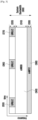
- FIG. 3 illustrates an example in which a service and data are transmitted in each of sub-bands 310, 320, and 330, obtained by dividing the entire system frequency bandwidth 300.
- Information associated with sub-band configuration may be predetermined, and the information may be transmitted to a terminal by a base station via higher layer signaling. According to another example, the information associated with the sub-band may be arbitrarily divided by a base station or a network node and services may be provided to the terminal without transmitting separate pieces of sub-band configuration information.
- FIG. 3 illustrates an example in which a service and data are transmitted in each of sub-bands 310, 320, and 330, obtained by dividing the entire system frequency bandwidth 300.
- Information associated with sub-band configuration may be predetermined, and the information may be transmitted to a terminal by a base station via higher layer signaling. According to another example, the information associated with the sub-band may be arbitrarily divided by a base station or a network node and services may be provided to the terminal without transmitting separate pieces of
- the maximum number of layers for one TB for UL-SCH is given by X, and is determined as follows: Configuration 1: If the parameter maxRank included in higher layer signaling pusch-Config is configured, the maximum value among the maxRank values defined for all BWPs of the serving cell is determined to be a value of X.
- the maxRank is not configured, the maximum number of layers for the PUSCH supported by the UE in the serving cell is determined to be X.
- Configuration 4 In a case of not corresponding to configuration 1, configuration 2, and configuration 3, X is configured to be one.
- only one of the higher layer parameters maxNumberMIMO-LayersCB-PUSCH and maxNumberMIMO-LayersNonCB-PUSCH may be replaced with either maxNumberMIMO-LayersCB-PUSCH or maxNumberMIMO-LayersNonCB-PUSCH and applied to the conditional statement.
- the conditions for the two parameters of maxNumberMIMO-LayersCB-PUSCH and maxNumberMIMO-LayersNonCB-PUSCH are required to be specified because the two parameters may be reported to the base station, which are parameters for the maximum number of layers indicating UE capability, and thus a clear definition of using one of the two parameters may be necessary for common understanding between the UE and the base station.
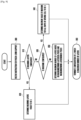
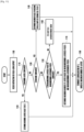
- FIG. 11 An example of the operation diagram of modified configurations B-1, B-2, B-3, and B-4 for rate matching in consideration of the PUSCH-LBRM is shown in FIG. 11 .
- FIG. 11 illustrates an example of an operation of a UE for supporting PUSCH-LBRM according to configuration B according to an embodiment of the disclosure.
- operations 1100, 1110, 1120, 1130, and 1140 of FIG. 11 are the same as those of operations 900, 910, 920, 930, and 940 of FIG. 9 .
- operation 1150 operation is distinguished in consideration of a case in which maxNumberMIMO-LayersCB-PUSCH or maxNumberMIMO-LayersNonCB-PUSCH is configured via higher layer signaling and a case in which maxNumberMIMO-LayersCB-PUSCH or maxNumberMIMO-LayersNonCB-PUSCH is not configured via higher layer signaling.
- the maximum number of layers "X" may be determined based on the value or the values based on the described method (indicated by reference numeral 1170), and if both parameters are not configured, X may be configured to be a predetermined value in operation 1160.
- Operations 1150 and 1170 may be expressed in various ways. For example, if only one of maxNumberMIMO-LayersCB-PUSCH and maxNumberMIMO-LayersNonCB-PUSCH is configured, the parameter is determined to be the maximum layer number "X", and if both the maxNumberMIMO-LayersCB-PUSCH and the maxNumberMIMO-LayersNonCB-PUSCH are configured, the maximum number of layers "X" is determined based on the two parameters (not shown).
- the process of determining the maximum number of layers "X" based on the two parameters may be represented by using a method, such as max (maxNumberMIMO-LayersCB-PUSCH, maxNumberMIMO-LayersNonCB-PUSCH) or min (maxNumberMIMO-LayersCB-PUSCH, maxNumberMIMO-LayersNonCB-PUSCH).
- decoding is possible if both a base station and a terminal, or both a transmitter and a receiver maintain the same configuration or the promised configuration, and various combinations of the configurations mentioned in the disclosure are possible.
- the fourth embodiment relates to a method and apparatus for applying an efficient uplink LBRM (UL-SCH LBRM or PUSCH LBRM) in performing data transmission.
- UL-SCH LBRM UL-SCH LBRM or PUSCH LBRM
- the maximum number of layers for one TB for UL-SCH is given by X, and is determined as follows.
- the maximum number of layers for the PUSCH supported by the UE in the serving cell is determined to be X.
- Configuration 4 In a case of not corresponding to configurations 1, 2 and 3, no LBRM is applied (i.e., no LBRM is applied if the maximum number of layers cannot be determined irrespective of the instruction for LBRM).
- the last part of the conditional statement may be expressed as "otherwise, no LBRM is applied".
- the configuration 3 may be more clearly indicated using maxNumberMIMO-LayersCB-PUSCH or maxNumberMIMO-LayersNonCB-PUSCH, as follows.
- the maximum number of layers for one TB for UL-SCH is given by X, and is determined as follows.
- the maxMIMO-Layers and the maxRank are not configured, and the parameters maxNumberMIMO-LayersCB-PUSCH and maxNumberMIMO-LayersNonCB-PUSCH are configured, the maximum value among the parameters maxNumberMIMO-LayersCB-PUSCH or maxNumberMIMO-LayersNonCB-PUSCH is determined to be a value of X.
- Configuration 5 In a case of not corresponding to configurations 1, 2, 3, and 4, LBRM is not applied.
- configuration 1, configuration 2, configuration 3, and configuration 4, and configuration 5 may be expressed as follows.
- the part specified and applied as “provided” may be used interchangeably with “given” or “configured” or may have the same meaning with each other. That is, “provided” in the conditional statement may be modified to "given” or “configured” and applied thereto.
- the maximum of maxNumberMIMO-LayersCB-PUSCH and maxNumberMIMO-LayersNonCB-PUSCH may be replaced with max (maxNumberMIMO-LayersCB-PUSCH, maxNumberMIMO-LayersNonCB-PUSCH) and applied to the conditional statement.
- only one of the higher layer parameters maxNumberMIMO-LayersCB-PUSCH and maxNumberMIMO-LayersNonCB-PUSCH may be replaced with either maxNumberMIMO-LayersCB-PUSCH or maxNumberMIMO-LayersNonCB-PUSCH and applied to the conditional statement.
- configuration 4 of the [Configuration C-2 for rate matching in consideration of PUSCH-LBRM] may be omitted, and in a case where a system in which only one of maxNumberMIMO-LayersCB-PUSCH and maxNumberMIMO-LayersNonCB-PUSCH is always configured in the [Configuration C-2 for rate matching in consideration of PUSCH-LBRM], it would be obvious that configuration 3 thereof is omissible.
- the maximum number of layers for one TB for UL-SCH is given by X, and is determined as follows.
- the maxRank is not configured, the maximum number of layers for the PUSCH supported by the UE in the serving cell is determined to be X.
- Configuration 3 In a case of not corresponding to configuration 1 and configuration 2, LBRM is not applied.
- the maximum number of layers for one TB for UL-SCH is given by X, and is determined as follows: Configuration 1: If the parameter maxRank included in higher layer signaling pusch-Config is configured, the maximum value among the maxRank values defined for all BWPs of the serving cell is determined to be a value of X.
- Configuration 4 In a case of not corresponding to configurations 1, 2, and 3, LBRM is not applied.
- only one of the higher layer parameters maxNumberMIMO-LayersCB-PUSCH and maxNumberMIMO-LayersNonCB-PUSCH may be replaced with either maxNumberMIMO-LayersCB-PUSCH or maxNumberMIMO-LayersNonCB-PUSCH and applied to the conditional statement.
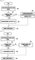
- FIG. 12 illustrates an example of an operation diagram of modified configurations C-1, C2, C-3, and C-4 for rate matching in consideration of the PUSCH-LBRM according to an embodiment of the disclosure.
- FIG. 12 illustrates an example of an operation of a UE for supporting PUSCH-LBRM according to configuration C.
- operations 1200, 1210, 1220, 1230, 1240, 1250, and 1270 of FIG. 12 are similar to operations 1100, 1110, 1120, 1130, 1140, 1150, and 1170 of FIG. 11 , but if maxNumberMIMO-LayersCB-PUSCH or maxNumberMIMO-LayersNonCB-PUSCH is not configured via higher layer signaling, the UE may not configure the maximum number of layers "X" and then apply a process of postponing applying of LBRM until at least one value of maxMIMO-Layers, maxRank, maxNumberMIMO-LayersCB-PUSCH, or maxNumberMIMO-LayersNonCB-PUSCH is configured via higher layer signaling (indicated by reference numeral 1260). If the value of parameter maxMIMO-Layers included in the PUSCH-ServingCellConfig configured at the base station is the same as the maxRank value included in the pusch-Config,
- a fifth embodiment relates to a method and apparatus for applying an efficient uplink LBRM (UL-SCH LBRM or PUSCH LBRM) in performing data transmission.
- UL-SCH LBRM or PUSCH LBRM efficient uplink LBRM
- TBS LBRM is determined based on the maximum number of layers of a PUSCH or a PDSCH configured via higher layer signaling (e.g., RRC).
- RRC higher layer signaling
- a method for solving the problem has been proposed in the third embodiment and the fourth embodiment, and the proposed method may be more simply expressed as follows.
- the maximum number of layers for one TB for UL-SCH is given by X, and is determined as follows.
- Configuration 4 In a case of not corresponding to configuration 1, configuration 2, and configuration 3, X is configured to be one.
- configuration 1 may be omitted in the above [Configuration D-1 for rate matching in consideration of the PUSCH-LBRM ]. It should be noted that various modifications are possible in a case of configuration 4 in the [Configuration D-1 for rate matching in consideration of PUSCH-LBRM ].
- "X" may be configured to be a predetermined another certain integer, or configured to be a certain value, such as a value mandated as the maximum number of layers determined to be supported by the UE in the band.
- the maximum number of layers determined to be supported by the UE in the band may differ for each frequency range.
- the UE may have to unconditionally support four layers, and in FR2, the UE may have to support two layers. Therefore, in this case, X may be configured to be 4 for a carrier belonging to FR1 and X may be configured to be 2 for a carrier belonging to FR2. As such, a value of X may be differently defined in FR1 and FR2.
- X 1, but it is not necessarily limited thereto. Further, the disclosure may consider the case of not applying or postponing LBRM.
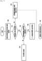
- FIG. 13 illustrates an example of the operation diagram of the modified configuration D-1 for rate matching in consideration of PUSCH-LBRM according to an embodiment of the disclosure.
- FIG. 13 illustrates an example of an operation of a UE of supporting PUSCH-LBRM according to configuration D.
- operations 1300, 1310, 1320, 1330, and 1340 of FIG. 11 are similar to operations 1100, 1110, 1120, 1130, and 1140 of FIG. 11 , but if the maxRank is not configured in operation 1330, the UE may determine whether UE capability is reported in operation 1350. In operation 1350, if the UE determines that the UE capability has been reported, X is configured to be the maximum number of layers supported by the UE, in operation 1370.
- the sixth embodiment relates to a method and apparatus for applying an efficient downlink LBRM (PDSCH-LBRM, DL-SCH LBRM, or PCH LBRM) in performing data transmission.
- PDSCH-LBRM efficient downlink LBRM
- DL-SCH LBRM DL-SCH LBRM
- PCH LBRM PCH LBRM
- TBS LBRM is determined based on the following configuration.
- the maximum number of layers for one TB for DL-SCH/PCH is given by the minimum value among X and 4 and is determined as follows.
- Configuration 2 In a case of not corresponding to configuration 1, X is determined to be the maximum number of layers for the PDSCH supported by the UE in the serving cell.
- FIG. 14 illustrates an example of terminal operation for the configuration of [Configuration for rate matching in consideration of PDSCH-LBRM] for PDSCH-LBRM according to an embodiment of the disclosure.
- FIG. 14 illustrates an embodiment of a terminal operation for PDSCH-LBRM support.
- the terminal receives an instruction for PDSCH-LBRM (indicated by reference numeral 1400), first, at least one processor identifies whether the parameter maxMIMO-Layer is configured (indicated by reference numeral 1410). If the parameter maxMIMO-Layer is configured, the terminal determines a value of parameter maxMIMO-Layer to be a value of X (indicated by reference numeral 1420), and may terminate a process of determining the value of X for the PDSCH-LBRM (indicated by reference numeral 1440).
- the terminal determines the maximum number of layers for the PDSCH supported by a UE in a serving cell to be X (indicated by reference numeral 1430), and may terminate a process of determining the value of X for the PDSCH-LBRM (indicated by reference numeral 1440).
- Operation 1420 of FIG. 14 which corresponds to configuration 2 in the [Configuration for rate matching in consideration of PDSCH-LBRM], includes a process of determining X to be the maximum number of layers for the PDSCH supported by the UE in the serving cell.
- the definition of the maximum number of layers is somewhat ambiguous, so a clearer definition is needed.
- a value of X may be determined based on the parameter.
- maxNumberMIMO-Layers-PDSCH is configured (or given)
- a value of the maxNumberMIMO-Layers-PDSCH may be determined to be X.
- the maximum number of layers for one TB for DL-SCH/PCH is given by the minimum value among X and 4, and is determined as follows.
- Configuration 2 In a case of not corresponding to configuration 1, X is determined to be the parameter maxNumberMIMO-Layers-PDSCH of higher layer signaling.
- FIG. 15 illustrates an example of a terminal operation for the configuration of [Modified configuration E-1 for rate matching in consideration of PDSCH-LBRM] for PDSCH-LBRM according to an embodiment of the disclosure.
- FIG. 15 illustrates an embodiment of an operation of a terminal for supporting PDSCH-LBRM according to configuration E.
- the UE receives an instruction for PDSCH-LBRM (indicated by reference numeral 1500), first, at least one processor identifies whether the parameter maxMIMO-Layer is configured (indicated by reference numeral 1510). If the parameter maxMIMO-Layer is configured, the UE may determine a value of the parameter maxMIMO-Layer to be a value of X, and terminate a process of determining the value of X for the PDSCH-LBRM (indicated by reference numeral 1540).
- the UE may determine the maxNumberMIMO-LayersPDSCH to be X (indicated by reference numeral 1530), and may terminate a process of determining the value of X for the PDSCH-LBRM (indicated by reference numeral 1540).
- the seventh embodiment relates to a method and apparatus for applying an efficient downlink LBRM (PDSCH LBRM, DL-SCH LBRM, or PCH LBRM) in performing data transmission.
- PDSCH-LBRM an efficient downlink LBRM
- TBS LBRM is determined based on the maximum number of layers of a PUSCH or a PDSCH, configured via higher layer signaling (e.g., RRC).
- RRC higher layer signaling
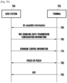
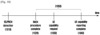
- a problem may occur in a case of applying of LBRM. That is, there is a likelihood that the configuration of the maximum number of layers of the PUSCH or PDSCH may be different between a gNB and a UE during a period of time 1050 between an operation 1020 in which the RACH procedure is completed and an operation 1040 in which the UE capability reporting is completed, in FIG. 10 .
- the UE may not immediately decode the PDSCH after the RACH procedure, the UE may not receive any RRC configuration message.
- One solution to the problem is to fix a value of the maximum number of layers "X" to a predetermined value or integer during a period of time 1050 of FIG. 10 .
- X 1, but the value of X is not limited thereto.
- the maximum number of layers for one TB for DL-SCH/PCH is given by the minimum value among X and 4, and is determined as follows.
- Configuration 3 In a case of not corresponding to configuration 1 and configuration 2, X is configured to be one.
- Configuration 2 in the [Configuration F-1 for rate matching in consideration of PDSCH-LBRM] may be expressed in another form as follows.
- the maximum number of layers for one TB for DL-SCH/PCH is given by the minimum value among X and 4, and is determined as follows.
- the maximum supported modulation order to be applied for downlink in the carrier in the max data rate calculation is given by the maximum modulation order that UE supports for downlink.
- the maximum supported modulation order applied for calculating the maximum data rate is defined as the maximum modulation order supported by a UE, but is not limited thereto and may be defined through another rule. For example, another predetermined specific integer may be configured or different values or different rules may be applied depending on a band, FR1, or FR2.
- the network may use a modulation order on this serving cell which is higher than the value indicated in this field as long as UE supports the modulation of higher value for uplink.
- the maximum supported modulation order to be applied for uplink in the carrier in the max data rate calculation is given by the maximum modulation order that UE supports for uplink.
- the maximum supported modulation order applied for calculation of the maximum data rate is defined as the maximum modulation order supported by a UE, but it is not limited thereto and it is obvious that it may be defined through other rules. For example, it is obvious that another predetermined specific integer may be configured or different values or different rules may be applied depending on a band, FR1, or FR2.
- supportedModulationOrderDL and supportedModulationOrderUL may be redefined, as follows.
- the network may use a modulation order on this serving cell which is higher than the value indicated in this field as long as UE supports the modulation of higher value for uplink.
- the higher layer signaling (or parameter) maxNumberMIMO-LayersCB-PUSCH and maxNumberMIMO-LayersNonCB-PUSCH are configured at the same time, provided is an example of determining the value of X, based on the maximum value among the two values, but it is not necessarily limited thereto, and more diverse rules may be applied thereto.
- the value of X is differently configured based on txConfig information included in the PUSCH-Config among system information.
- the PUSCH-Config information includes txConfig information as follows, and definition thereof is as follows.
- UE uses codebook based or non-codebook based transmission. If the field is absent, the UE transmits PUSCH on one antenna port.
- the value of X may be determined according to configuration of the txConfig.
- X may be configured to be maxNumberMIMO-LayersCB-PUSCH, or if the value of txConfig value is nonCodebook, X may be configured to be maxNumberMIMO-LayersNonCB-PUSCH. It goes without saying that various embodiments may be applied without being limited thereto.
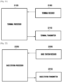
- FIGS. 21 and 22 each illustrate a transmitter, a receiver, and a processor of a terminal and a base station for performing embodiments.
- the receiver, the processor, and the transmitter of the base station and the terminal may operate according to the above-described embodiments.
- a terminal of the disclosure may include a terminal receiver 2100, a terminal transmitter 2110, and a terminal processor 2120.
- the terminal receiver 2100 and the terminal transmitter 2110 may be collectively referred to as a transceiver.
- the transceiver may transmit or receive a signal to or from a base station.
- the signal may include control information and data.
- the transceiver may include an RF transmitter for up-converting and amplifying a frequency of the transmitted signal, and an RF receiver for low-noise amplifying the received signal and down-converting a frequency of the received signal.
- the transceiver may receive a signal through a wireless channel, output the signal to the terminal processor 2120, and transmit the signal output from the terminal processor 2120 through a wireless channel.
- the terminal processor 2120 may control a series of processes such that the terminal may operate according to the above-described embodiment.
- the terminal receiver 2100 receives data and control information including scheduling information for data transmission from the base station, and the terminal processor 2120 may compare a peak data rate and a scheduled data amount of the terminal and determine whether to decode and transmit the same, and perform signal processing according thereto. Thereafter, signals that need to be transmitted by the terminal transmitter 2110 may be transmitted to the base station.
- a base station of the disclosure may include a base station receiver 2200, a base station transmitter 2210, and a base station processor 2220.
- the base station receiver 2200 and the base station transmitter 2210 may be collectively referred to as a transceiver.
- the transceiver may transmit or receive a signal to or from a terminal.
- the signal may include control information and data.
- the transceiver may include an RF transmitter for up-converting and amplifying a frequency of the transmitted signal, and an RF receiver for low-noise amplifying the received signal and down-converting a frequency of the received signal.
- the transceiver may receive a signal through a wireless channel, output the signal to the base station processor 2220, and transmit the signal output from the base station processor 2220 through a wireless channel.
- the base station processor 2220 may control a series of processes such that the base station may operate according to the above-described embodiment. For example, the base station processor 2220 may calculate a peak data rate of the terminal, determine TBS within a range not exceeding the peak data rate, and schedule the TBS so as to generate control information.
- control information generated by the base station transmitter 2210 may be transmitted, and the base station receiver 2200 may receive an uplink data signal and feedback of the terminal.
Landscapes
- Engineering & Computer Science (AREA)
- Signal Processing (AREA)
- Computer Networks & Wireless Communication (AREA)
- Quality & Reliability (AREA)
- Physics & Mathematics (AREA)
- Mathematical Physics (AREA)
- Mobile Radio Communication Systems (AREA)
Claims (12)
- Verfahren, das von einer Basisstation in einem Kommunikationssystem durchgeführt wird, wobei das Verfahren Folgendes umfasst:Identifizieren, dass ein Downlink-Anpassen begrenzter Pufferraten, LBRM, angewendet wird;Übertragen einer Konfiguration eines Bandbreitenteils, BWP, für jede einer Vielzahl von BWPs einer bedienenden Zelle in der Signalisierung der höheren Schicht an ein Endgerät, wobei jede BWP-Konfiguration eine Modulations- und Kodierungsschema-, MCS,-Tabellenkonfiguration umfasst, die einem gemeinsam genutzten physikalischen Downlink-Kanal, PDSCH, für einen entsprechenden BWP der bedienenden Zelle zugeordnet ist;Kodieren der an das Endgerät zu übertragenden Informationsbits unter Verwendung eines Low-Density-Parity-Check-Codes, LDPC;Bestimmen einer Transportblockgröße, TBS, für das Downlink-LBRM;Identifizieren der Länge eines Ringpuffers Ncb basierend auf dem TBS für das Downlink-LBRM;Bestimmen einer Bitfolge basierend auf den Ncb und den kodierten Informationsbits; undÜbertragen der Bitfolge an das Endgerät,wobei der TBS für das Downlink-LBRM basierend auf einer maximalen Downlink-Modulationsordnung bestimmt wird,wobei die maximale Downlink-Modulationsordnung für die bedienende Zelle 8 entspricht, wenn mindestens eine MCS-Tabellenkonfiguration für mindestens einen BWP der bedienenden Zelle auf 256QAM eingestellt ist, undwobei die maximale Downlink-Modulationsordnung für die bedienende Zelle 6 entspricht, falls alle MCS-Tabellenkonfigurationen für die Vielzahl von BWPs der bedienenden Zelle auf 64QAM eingestellt sind.
- Verfahren nach Anspruch 1, wobei der TBS für das Downlink-LBRM ferner auf einer maximalen Anzahl von Schichten für einen Transportblock, TB, basiert,wobei die Anzahl der Schichten für einen TB dem Minimum von X und 4 entspricht, undwobei das X Informationen über maximale MIMO-Schichten für den PDSCH zugeordnet ist, falls die Informationen über maximale MIMO-Schichten des PDSCH übertragen werden.
- Verfahren nach Anspruch 2, wobei X einer maximalen Anzahl von Schichten für den vom Endgerät unterstützten PDSCH entspricht, falls die Information über maximale MIMO-Schichten des PDSCH nicht übertragen wird.
- Verfahren, das von einem Endgerät in einem Kommunikationssystem durchgeführt wird, wobei das Verfahren Folgendes umfasst:Identifizieren, dass ein Downlink-Anpassen begrenzter Pufferraten, LBRM, angewendet wird;Empfangen einer Konfiguration eines Bandbreitenteils, BWP, für jede einer Vielzahl von BWPs einer bedienenden Zelle in der Signalisierung der höheren Schicht von einer Basisstation, wobei jede BWP-Konfiguration eine Modulations- und Kodierungsschema-, MCS,-Tabellenkonfiguration umfasst, die einem gemeinsam genutzten physikalischen Downlink-Kanal, PDSCH, für einen entsprechenden BWP der bedienenden Zelle zugeordnet ist;Bestimmen einer Transportblockgröße, TBS, für das Downlink-LBRM;Identifizieren einer Länge eines Ringpuffers Ncb zum Empfangen von Informationsbits von der Basisstation basierend auf dem TBS für das Downlink LBRM;Empfangen eines Downlink-Datensignals von der Basisstation; undErhalten von Informationsbits, die dem Downlink-Datensignal zugeordnet sind, basierend auf dem Ncb,wobei der TBS für das Downlink-LBRM basierend auf einer maximalen Downlink-Modulationsordnung bestimmt wird,wobei die maximale Downlink-Modulationsordnung für die bedienende Zelle 8 entspricht, falls mindestens eine MCS-Tabellenkonfiguration für mindestens einen BWP aus der Vielzahl von BWPs der bedienenden Zelle auf 256QAM eingestellt ist, undwobei die maximale Downlink-Modulationsordnung für die bedienende Zelle 6 entspricht, falls alle MCS-Tabellenkonfigurationen für die Vielzahl von BWPs der bedienenden Zelle auf 64QAM eingestellt sind.
- Verfahren nach Anspruch 4, wobei der TBS für das Downlink-LBRM ferner auf einer maximalen Anzahl von Schichten für einen Transportblock, TB, basiert,wobei die Anzahl der Schichten für einen TB dem Minimum von X und 4 entspricht, undwobei das X durch Informationen über maximale MIMO-Schichten für den PDSCH gegeben ist, falls die Informationen über maximale MIMO-Schichten des PDSCH konfiguriert sind.
- Verfahren nach Anspruch 5, wobei X einer maximalen Anzahl von Schichten für den vom Endgerät unterstützten PDSCH entspricht, falls die Information über maximale MIMO-Schichten des PDSCH nicht konfiguriert ist.
- Basisstation in einem Kommunikationssystem, wobei die Basisstation Folgendes umfasst:einen Transceiver (2200, 2210); undmindestens einen Prozessor (2220), der konfiguriert ist zum:Identifizieren, dass ein Downlink-Anpassen begrenzter Pufferraten, LBRM, angewendet wird;Übertragen einer Konfiguration eines Bandbreitenteils, BWP, für jede einer Vielzahl von BWPs einer bedienenden Zelle in der Signalisierung der höheren Schicht an ein Endgerät, wobei jede BWP-Konfiguration eine Modulations- und Kodierungsschema-, MCS,-Tabellenkonfiguration umfasst, die einem gemeinsam genutzten physikalischen Downlink-Kanal, PDSCH, für einen entsprechenden BWP der bedienenden Zelle zugeordnet ist;Kodieren der an das Endgerät zu übertragenden Informationsbits unter Verwendung eines Low-Density-Parity-Check-Codes, LDPC;Bestimmen einer Transportblockgröße, TBS, für das Downlink-LBRM;Identifizieren einer Länge eines Ringpuffers Ncb basierend auf dem TBS für das Downlink-LBRM;Bestimmen einer Bitfolge basierend auf den Ncb und den kodierten Informationsbits; undÜbertragen der Bitfolge an das Endgerät,wobei der TBS für das Downlink-LBRM basierend auf einer maximalen Downlink-Modulationsordnung bestimmt wird,wobei die maximale Downlink-Modulationsordnung für die bedienende Zelle 8 entspricht, wenn mindestens eine MCS-Tabellenkonfiguration für mindestens einen BWP der bedienenden Zelle auf 256QAM eingestellt ist, undwobei die maximale Downlink-Modulationsordnung für die bedienende Zelle 6 entspricht, falls alle MCS-Tabellenkonfigurationen für die Vielzahl von BWPs der bedienenden Zelle auf 64QAM eingestellt sind.
- Basisstation nach Anspruch 7, wobei der TBS für das Downlink-LBRM ferner auf einer maximalen Anzahl von Schichten für einen Transportblock, TB, basiert,wobei die Anzahl der Schichten für einen TB dem Minimum von X und 4 entspricht, undwobei das X Informationen über maximale MIMO-Schichten für den PDSCH zugeordnet ist, falls die Informationen über maximale MIMO-Schichten des PDSCH übertragen werden.
- Basisstation nach Anspruch 8, wobei X einer maximalen Anzahl von Schichten für den vom Endgerät unterstützten PDSCH entspricht, falls die Information über maximale MIMO-Schichten des PDSCH nicht übertragen wird.
- Endgerät in einem Kommunikationssystems, wobei das Endgerät Folgendes umfasst:einen Transceiver (2100, 2110); undmindestens einen Prozessor (2120), der konfiguriert ist zum:Identifizieren, dass ein Downlink-Anpassen begrenzter Pufferraten, LBRM, angewendet wird;Empfangen einer Konfiguration eines Bandbreitenteils, BWP, für jede einer Vielzahl von BWPs einer bedienenden Zelle in der Signalisierung der höheren Schicht von einer Basisstation, wobei jede BWP-Konfiguration eine Modulations- und Kodierungsschema-, MCS,-Tabellenkonfiguration umfasst, die einem gemeinsam genutzten physikalischen Downlink-Kanal, PDSCH, für einen entsprechenden BWP der bedienenden Zelle zugeordnet ist;Bestimmen einer Transportblockgröße, TBS, für das Downlink-LBRM;Identifizieren einer Länge eines Ringpuffers Ncb zum Empfangen von Informationsbits von der Basisstation basierend auf dem TBS für das Downlink LBRM;Empfangen eines Downlink-Datensignals von der Basisstation, undErhalten von Informationsbits, die dem Downlink-Datensignal zugeordnet sind, basierend auf dem Ncb,wobei der TBS für das Downlink-LBRM basierend auf einer maximalen Downlink-Modulationsordnung bestimmt wird,wobei die maximale Downlink-Modulationsordnung für die bedienende Zelle 8 entspricht, falls mindestens eine MCS-Tabellenkonfiguration für mindestens einen BWP aus der Vielzahl von BWPs der bedienenden Zelle auf 256QAM eingestellt ist, undwobei die maximale Downlink-Modulationsordnung für die bedienende Zelle 6 entspricht, falls alle MCS-Tabellenkonfigurationen für die Vielzahl von BWPs der bedienenden Zelle auf 64QAM eingestellt sind.
- Endgerät nach Anspruch 10, wobei der TBS für das Downlink-LBRM ferner auf einer maximalen Anzahl von Schichten für einen Transportblock, TB, basiert,wobei die Anzahl der Schichten für einen TB dem Minimum von X und 4 entspricht, undwobei das X durch Informationen über maximale MIMO-Schichten für den PDSCH gegeben ist, falls die Informationen über maximale MIMO-Schichten des PDSCH konfiguriert sind.
- Endgerät nach Anspruch 11, wobei X einer maximalen Anzahl von Schichten für den PDSCH entspricht, die von dem Endgerät unterstützt werden, falls die Information über maximale MIMO-Schichten des PDSCH nicht konfiguriert ist.
Priority Applications (1)
| Application Number | Priority Date | Filing Date | Title |
|---|---|---|---|
| EP25151662.1A EP4518269A3 (de) | 2019-02-15 | 2020-02-17 | Verfahren und vorrichtung zum senden oder empfangen von daten in einem kommunikationssystem |
Applications Claiming Priority (4)
| Application Number | Priority Date | Filing Date | Title |
|---|---|---|---|
| KR20190018093 | 2019-02-15 | ||
| KR20190022813 | 2019-02-26 | ||
| KR1020190040464A KR102720515B1 (ko) | 2019-02-15 | 2019-04-05 | 통신시스템에서 데이터 송수신 방법 및 장치 |
| PCT/KR2020/002216 WO2020167088A1 (en) | 2019-02-15 | 2020-02-17 | Method and apparatus for transmission or reception of data in communication system |
Related Child Applications (2)
| Application Number | Title | Priority Date | Filing Date |
|---|---|---|---|
| EP25151662.1A Division-Into EP4518269A3 (de) | 2019-02-15 | 2020-02-17 | Verfahren und vorrichtung zum senden oder empfangen von daten in einem kommunikationssystem |
| EP25151662.1A Division EP4518269A3 (de) | 2019-02-15 | 2020-02-17 | Verfahren und vorrichtung zum senden oder empfangen von daten in einem kommunikationssystem |
Publications (4)
| Publication Number | Publication Date |
|---|---|
| EP3854015A1 EP3854015A1 (de) | 2021-07-28 |
| EP3854015A4 EP3854015A4 (de) | 2021-11-17 |
| EP3854015C0 EP3854015C0 (de) | 2025-04-02 |
| EP3854015B1 true EP3854015B1 (de) | 2025-04-02 |
Family
ID=72242232
Family Applications (2)
| Application Number | Title | Priority Date | Filing Date |
|---|---|---|---|
| EP25151662.1A Pending EP4518269A3 (de) | 2019-02-15 | 2020-02-17 | Verfahren und vorrichtung zum senden oder empfangen von daten in einem kommunikationssystem |
| EP20755970.9A Active EP3854015B1 (de) | 2019-02-15 | 2020-02-17 | Verfahren und vorrichtung zum senden oder empfangen von daten in einem kommunikationssystem |
Family Applications Before (1)
| Application Number | Title | Priority Date | Filing Date |
|---|---|---|---|
| EP25151662.1A Pending EP4518269A3 (de) | 2019-02-15 | 2020-02-17 | Verfahren und vorrichtung zum senden oder empfangen von daten in einem kommunikationssystem |
Country Status (6)
| Country | Link |
|---|---|
| US (1) | US12556302B2 (de) |
| EP (2) | EP4518269A3 (de) |
| KR (1) | KR102720515B1 (de) |
| CN (2) | CN119212102A (de) |
| AU (2) | AU2020221134B2 (de) |
| CA (1) | CA3119323A1 (de) |
Families Citing this family (8)
| Publication number | Priority date | Publication date | Assignee | Title |
|---|---|---|---|---|
| US12218751B2 (en) | 2019-07-18 | 2025-02-04 | Samsung Electronics Co., Ltd | Apparatus and method for limited buffer rate matching (LBRM) in a wireless communication system |
| KR102919722B1 (ko) | 2020-09-18 | 2026-01-30 | 삼성전자 주식회사 | 무선 셀룰라 통신 시스템에서 그룹캐스트 및 브로드캐스트용 데이터 송수신 방법 및 장치 |
| CN116073942A (zh) * | 2021-10-29 | 2023-05-05 | 华为技术有限公司 | 通信方法和通信装置 |
| WO2023137743A1 (en) * | 2022-01-24 | 2023-07-27 | Qualcomm Incorporated | Multi-beam communications using receiver assistance information |
| CN116647305A (zh) * | 2022-02-15 | 2023-08-25 | 华为技术有限公司 | 编码方法、译码方法以及相关装置 |
| EP4580292A1 (de) * | 2022-08-07 | 2025-07-02 | Shanghai Langbo Communication Technology Company Limited | Verfahren und vorrichtung zur verwendung in einem knoten für drahtlose kommunikation |
| CN116155452B (zh) * | 2023-04-21 | 2023-09-15 | 翱捷科技股份有限公司 | 一种ldpc码速率匹配最大层数的确定方法及装置 |
| WO2026029224A1 (ko) * | 2024-07-31 | 2026-02-05 | 엘지전자 주식회사 | 수송 블록을 전송하는 방법, 통신 기기, 프로세싱 장치, 및 저장 매체, 그리고 수송 블록을 수신하는 방법, 통신 기기, 프로세싱 장치, 및 저장 매체 |
Family Cites Families (16)
| Publication number | Priority date | Publication date | Assignee | Title |
|---|---|---|---|---|
| CN105850090B (zh) | 2014-01-30 | 2019-12-13 | 英特尔公司 | 用于与节点无缝操作的能够256-qam的用户设备的机制 |
| WO2017034329A1 (ko) * | 2015-08-25 | 2017-03-02 | 엘지전자 주식회사 | 무선 통신 시스템에서 must 전송을 위한 스케줄링 방법 및 이를 위한 장치 |
| US10225041B2 (en) | 2016-01-15 | 2019-03-05 | Qualcomm Incorporated | Methods and apparatus for higher modulation support in LTE |
| US10541781B2 (en) | 2016-01-29 | 2020-01-21 | Intel IP Corporation | Rate matching using low-density parity-check codes |
| US20180035409A1 (en) * | 2016-07-28 | 2018-02-01 | Nokia Solutions And Networks Oy | Mitigation of rate matching errors in a wireless network |
| CN108400832B (zh) * | 2017-02-06 | 2022-09-09 | 华为技术有限公司 | 数据处理方法和通信设备 |
| US11290911B2 (en) | 2017-02-24 | 2022-03-29 | Lg Electronics Inc. | Method for processing data block and method for HARQ ACK/NACK feedback |
| US11211953B2 (en) * | 2017-08-01 | 2021-12-28 | Lg Electronics Inc. | Rate matching performing method for LDPC code and communication device therefor |
| CN109391360B (zh) * | 2017-08-11 | 2022-04-12 | 中兴通讯股份有限公司 | 数据编码方法及装置 |
| US10979988B2 (en) * | 2017-11-07 | 2021-04-13 | Apple Inc. | Methods of limited buffer rate-matching (LBRM), pre-emption, and sidelink synchronization in new radio (NR) systems |
| US11025456B2 (en) * | 2018-01-12 | 2021-06-01 | Apple Inc. | Time domain resource allocation for mobile communication |
| CN110391870B (zh) | 2018-04-16 | 2022-04-29 | 华为技术有限公司 | 速率匹配的方法和装置,以及解速率匹配的方法和装置 |
| JP2019198013A (ja) | 2018-05-10 | 2019-11-14 | シャープ株式会社 | 端末装置および基地局装置 |
| CN110474739B (zh) | 2018-05-11 | 2022-06-28 | 中兴通讯股份有限公司 | 调制编码及cqi上报方法、装置、设备及存储介质 |
| US11695496B2 (en) | 2018-09-27 | 2023-07-04 | Qualcomm Incorporated | Modulation and coding scheme configuration determination |
| US11202298B2 (en) * | 2018-10-09 | 2021-12-14 | Qualcomm Incorporated | Resolving decodability for subsequent transmissions whose throughput exceeds a threshold |
-
2019
- 2019-04-05 KR KR1020190040464A patent/KR102720515B1/ko active Active
-
2020
- 2020-02-17 CA CA3119323A patent/CA3119323A1/en active Pending
- 2020-02-17 EP EP25151662.1A patent/EP4518269A3/de active Pending
- 2020-02-17 EP EP20755970.9A patent/EP3854015B1/de active Active
- 2020-02-17 CN CN202411279195.8A patent/CN119212102A/zh active Pending
- 2020-02-17 AU AU2020221134A patent/AU2020221134B2/en active Active
- 2020-02-17 CN CN202080006093.2A patent/CN113016154B/zh active Active
-
2023
- 2023-07-03 US US18/346,564 patent/US12556302B2/en active Active
-
2025
- 2025-03-19 AU AU2025202001A patent/AU2025202001A1/en active Pending
Non-Patent Citations (1)
| Title |
|---|
| INTEL CORPORATION: "Discussion on standardization impacts of UL 256QAM", vol. RAN WG1, no. Busan, Korea; 20160411 - 20160415, 18 April 2016 (2016-04-18), XP051097085, Retrieved from the Internet <URL:http://www.3gpp.org/ftp/tsg_ran/WG1_RL1/TSGR1_84b/Docs/> [retrieved on 20160418] * |
Also Published As
| Publication number | Publication date |
|---|---|
| AU2025202001A1 (en) | 2025-04-10 |
| CN113016154B (zh) | 2024-10-01 |
| US20230370195A1 (en) | 2023-11-16 |
| CA3119323A1 (en) | 2020-08-20 |
| CN113016154A (zh) | 2021-06-22 |
| US12556302B2 (en) | 2026-02-17 |
| EP3854015C0 (de) | 2025-04-02 |
| AU2020221134B2 (en) | 2024-12-19 |
| KR20200099941A (ko) | 2020-08-25 |
| AU2020221134A1 (en) | 2021-05-20 |
| CN119212102A (zh) | 2024-12-27 |
| EP3854015A1 (de) | 2021-07-28 |
| EP4518269A3 (de) | 2025-06-04 |
| KR20240154509A (ko) | 2024-10-25 |
| EP4518269A2 (de) | 2025-03-05 |
| EP3854015A4 (de) | 2021-11-17 |
| KR102720515B1 (ko) | 2024-10-23 |
Similar Documents
| Publication | Publication Date | Title |
|---|---|---|
| US11695506B2 (en) | Method and apparatus for transmission or reception of data in communication system | |
| US12568347B2 (en) | Method and apparatus for transmission and reception of groupcast and broadcast data in wireless cellular communication system | |
| EP3854015B1 (de) | Verfahren und vorrichtung zum senden oder empfangen von daten in einem kommunikationssystem | |
| EP3955494B1 (de) | Verfahren und vorrichtung zur teilweisen neuübertragung in einem drahtlosen zellularen kommunikationssystem | |
| EP3522415B1 (de) | Verfahren und vorrichtung zur datenübertragung in einem drahtlosen zellularen kommunikationssystem | |
| US12120713B2 (en) | Data communication method and device using multiple MCS in wireless communication system | |
| EP4489340A2 (de) | Vorrichtung und verfahren zur codierung und decodierung eines kanals in kommunikations- oder rundfunksystem | |
| EP3771120A1 (de) | Verfahren und vorrichtung zum senden und empfangen von steuerungsinformationen in einem zellulären drahtloskommunikationssystem | |
| EP3790327B1 (de) | Synchronisierungsverfahren und -vorrichtung zum gruppen-casting in drahtloskommunikationssystem | |
| US12047948B2 (en) | Method and device for transmitting and receiving data based on scheduling restriction condition | |
| CN107733565A (zh) | 用于在移动通信系统中解码数据的设备和方法 | |
| KR20180007584A (ko) | 무선 셀룰라 통신 시스템에서 이종 서비스간 공존 방법 및 장치 | |
| US11528741B2 (en) | Method and device for determining transmission time in wireless communication system | |
| US11356988B2 (en) | Method and apparatus for mapping uplink control information in wireless communication system | |
| US12069618B2 (en) | Method and device for transmitting/receiving signals in communication system | |
| EP3582559A1 (de) | Vorrichtung und verfahren zur uplink-leistungssteuerung in einem mobilfunksystem | |
| KR20200036717A (ko) | 무선 셀룰라 통신 시스템에서 그룹캐스트 피드백 송수신 방법 및 장치 | |
| EP4064595A1 (de) | Gerät und verfahren zum senden und empfangen von daten und steuersignalen in einem kommunikationssystem | |
| KR102953549B1 (ko) | 통신시스템에서 데이터 송수신 방법 및 장치 | |
| KR102953318B1 (ko) | 통신 시스템에서 데이터 및 제어 신호 송수신을 위한 장치 및 방법 |
Legal Events
| Date | Code | Title | Description |
|---|---|---|---|
| STAA | Information on the status of an ep patent application or granted ep patent |
Free format text: STATUS: THE INTERNATIONAL PUBLICATION HAS BEEN MADE |
|
| PUAI | Public reference made under article 153(3) epc to a published international application that has entered the european phase |
Free format text: ORIGINAL CODE: 0009012 |
|
| STAA | Information on the status of an ep patent application or granted ep patent |
Free format text: STATUS: REQUEST FOR EXAMINATION WAS MADE |
|
| 17P | Request for examination filed |
Effective date: 20210420 |
|
| AK | Designated contracting states |
Kind code of ref document: A1 Designated state(s): AL AT BE BG CH CY CZ DE DK EE ES FI FR GB GR HR HU IE IS IT LI LT LU LV MC MK MT NL NO PL PT RO RS SE SI SK SM TR |
|
| A4 | Supplementary search report drawn up and despatched |
Effective date: 20211019 |
|
| RIC1 | Information provided on ipc code assigned before grant |
Ipc: H04L 27/36 20060101ALI20211013BHEP Ipc: H04L 5/00 20060101ALI20211013BHEP Ipc: H04L 1/18 20060101ALI20211013BHEP Ipc: H04B 7/06 20060101ALI20211013BHEP Ipc: H04W 72/12 20090101ALI20211013BHEP Ipc: H04L 1/00 20060101AFI20211013BHEP |
|
| DAV | Request for validation of the european patent (deleted) | ||
| DAX | Request for extension of the european patent (deleted) | ||
| STAA | Information on the status of an ep patent application or granted ep patent |
Free format text: STATUS: EXAMINATION IS IN PROGRESS |
|
| 17Q | First examination report despatched |
Effective date: 20230103 |
|
| GRAP | Despatch of communication of intention to grant a patent |
Free format text: ORIGINAL CODE: EPIDOSNIGR1 |
|
| STAA | Information on the status of an ep patent application or granted ep patent |
Free format text: STATUS: GRANT OF PATENT IS INTENDED |
|
| INTG | Intention to grant announced |
Effective date: 20240522 |
|
| RAP3 | Party data changed (applicant data changed or rights of an application transferred) |
Owner name: SAMSUNG ELECTRONICS CO., LTD. |
|
| GRAJ | Information related to disapproval of communication of intention to grant by the applicant or resumption of examination proceedings by the epo deleted |
Free format text: ORIGINAL CODE: EPIDOSDIGR1 |
|
| STAA | Information on the status of an ep patent application or granted ep patent |
Free format text: STATUS: EXAMINATION IS IN PROGRESS |
|
| GRAP | Despatch of communication of intention to grant a patent |
Free format text: ORIGINAL CODE: EPIDOSNIGR1 |
|
| STAA | Information on the status of an ep patent application or granted ep patent |
Free format text: STATUS: GRANT OF PATENT IS INTENDED |
|
| INTC | Intention to grant announced (deleted) | ||
| INTG | Intention to grant announced |
Effective date: 20241011 |
|
| GRAS | Grant fee paid |
Free format text: ORIGINAL CODE: EPIDOSNIGR3 |
|
| GRAA | (expected) grant |
Free format text: ORIGINAL CODE: 0009210 |
|
| STAA | Information on the status of an ep patent application or granted ep patent |
Free format text: STATUS: THE PATENT HAS BEEN GRANTED |
|
| AK | Designated contracting states |
Kind code of ref document: B1 Designated state(s): AL AT BE BG CH CY CZ DE DK EE ES FI FR GB GR HR HU IE IS IT LI LT LU LV MC MK MT NL NO PL PT RO RS SE SI SK SM TR |
|
| REG | Reference to a national code |
Ref country code: GB Ref legal event code: FG4D |
|
| REG | Reference to a national code |
Ref country code: CH Ref legal event code: EP |
|
| REG | Reference to a national code |
Ref country code: DE Ref legal event code: R096 Ref document number: 602020048744 Country of ref document: DE |
|
| REG | Reference to a national code |
Ref country code: IE Ref legal event code: FG4D |
|
| U01 | Request for unitary effect filed |
Effective date: 20250424 |
|
| U07 | Unitary effect registered |
Designated state(s): AT BE BG DE DK EE FI FR IT LT LU LV MT NL PT RO SE SI Effective date: 20250430 |
|
| PG25 | Lapsed in a contracting state [announced via postgrant information from national office to epo] |
Ref country code: ES Free format text: LAPSE BECAUSE OF FAILURE TO SUBMIT A TRANSLATION OF THE DESCRIPTION OR TO PAY THE FEE WITHIN THE PRESCRIBED TIME-LIMIT Effective date: 20250402 |
|
| PG25 | Lapsed in a contracting state [announced via postgrant information from national office to epo] |
Ref country code: NO Free format text: LAPSE BECAUSE OF FAILURE TO SUBMIT A TRANSLATION OF THE DESCRIPTION OR TO PAY THE FEE WITHIN THE PRESCRIBED TIME-LIMIT Effective date: 20250702 Ref country code: GR Free format text: LAPSE BECAUSE OF FAILURE TO SUBMIT A TRANSLATION OF THE DESCRIPTION OR TO PAY THE FEE WITHIN THE PRESCRIBED TIME-LIMIT Effective date: 20250703 |
|
| PG25 | Lapsed in a contracting state [announced via postgrant information from national office to epo] |
Ref country code: PL Free format text: LAPSE BECAUSE OF FAILURE TO SUBMIT A TRANSLATION OF THE DESCRIPTION OR TO PAY THE FEE WITHIN THE PRESCRIBED TIME-LIMIT Effective date: 20250402 |
|
| PG25 | Lapsed in a contracting state [announced via postgrant information from national office to epo] |
Ref country code: HR Free format text: LAPSE BECAUSE OF FAILURE TO SUBMIT A TRANSLATION OF THE DESCRIPTION OR TO PAY THE FEE WITHIN THE PRESCRIBED TIME-LIMIT Effective date: 20250402 |
|
| PG25 | Lapsed in a contracting state [announced via postgrant information from national office to epo] |
Ref country code: RS Free format text: LAPSE BECAUSE OF FAILURE TO SUBMIT A TRANSLATION OF THE DESCRIPTION OR TO PAY THE FEE WITHIN THE PRESCRIBED TIME-LIMIT Effective date: 20250702 |
|
| PG25 | Lapsed in a contracting state [announced via postgrant information from national office to epo] |
Ref country code: IS Free format text: LAPSE BECAUSE OF FAILURE TO SUBMIT A TRANSLATION OF THE DESCRIPTION OR TO PAY THE FEE WITHIN THE PRESCRIBED TIME-LIMIT Effective date: 20250802 |
|
| PG25 | Lapsed in a contracting state [announced via postgrant information from national office to epo] |
Ref country code: SM Free format text: LAPSE BECAUSE OF FAILURE TO SUBMIT A TRANSLATION OF THE DESCRIPTION OR TO PAY THE FEE WITHIN THE PRESCRIBED TIME-LIMIT Effective date: 20250402 |
|
| PG25 | Lapsed in a contracting state [announced via postgrant information from national office to epo] |
Ref country code: CZ Free format text: LAPSE BECAUSE OF FAILURE TO SUBMIT A TRANSLATION OF THE DESCRIPTION OR TO PAY THE FEE WITHIN THE PRESCRIBED TIME-LIMIT Effective date: 20250402 |
|
| PG25 | Lapsed in a contracting state [announced via postgrant information from national office to epo] |
Ref country code: SK Free format text: LAPSE BECAUSE OF FAILURE TO SUBMIT A TRANSLATION OF THE DESCRIPTION OR TO PAY THE FEE WITHIN THE PRESCRIBED TIME-LIMIT Effective date: 20250402 |
|
| PLBE | No opposition filed within time limit |
Free format text: ORIGINAL CODE: 0009261 |
|
| STAA | Information on the status of an ep patent application or granted ep patent |
Free format text: STATUS: NO OPPOSITION FILED WITHIN TIME LIMIT |
|
| REG | Reference to a national code |
Ref country code: CH Ref legal event code: L10 Free format text: ST27 STATUS EVENT CODE: U-0-0-L10-L00 (AS PROVIDED BY THE NATIONAL OFFICE) Effective date: 20260211 |
|
| 26N | No opposition filed |
Effective date: 20260105 |
|
| U20 | Renewal fee for the european patent with unitary effect paid |
Year of fee payment: 7 Effective date: 20260223 |
|
| PGFP | Annual fee paid to national office [announced via postgrant information from national office to epo] |
Ref country code: GB Payment date: 20260122 Year of fee payment: 7 |