EP3854263B1 - Armlehne, insbesondere für einen bürostuhl - Google Patents
Armlehne, insbesondere für einen bürostuhl Download PDFInfo
- Publication number
- EP3854263B1 EP3854263B1 EP21000008.9A EP21000008A EP3854263B1 EP 3854263 B1 EP3854263 B1 EP 3854263B1 EP 21000008 A EP21000008 A EP 21000008A EP 3854263 B1 EP3854263 B1 EP 3854263B1
- Authority
- EP
- European Patent Office
- Prior art keywords
- armrest
- column
- arm support
- guide
- guide slot
- Prior art date
- Legal status (The legal status is an assumption and is not a legal conclusion. Google has not performed a legal analysis and makes no representation as to the accuracy of the status listed.)
- Active
Links
Images




Classifications
-
- A—HUMAN NECESSITIES
- A47—FURNITURE; DOMESTIC ARTICLES OR APPLIANCES; COFFEE MILLS; SPICE MILLS; SUCTION CLEANERS IN GENERAL
- A47C—CHAIRS; SOFAS; BEDS
- A47C1/00—Chairs adapted for special purposes
- A47C1/02—Reclining or easy chairs
- A47C1/022—Reclining or easy chairs having independently-adjustable supporting parts
- A47C1/03—Reclining or easy chairs having independently-adjustable supporting parts the parts being arm-rests
- A47C1/0308—Reclining or easy chairs having independently-adjustable supporting parts the parts being arm-rests adjustable by rotation
-
- A—HUMAN NECESSITIES
- A47—FURNITURE; DOMESTIC ARTICLES OR APPLIANCES; COFFEE MILLS; SPICE MILLS; SUCTION CLEANERS IN GENERAL
- A47C—CHAIRS; SOFAS; BEDS
- A47C7/00—Parts, details, or accessories of chairs or stools
- A47C7/54—Supports for the arms
- A47C7/541—Supports for the arms of adjustable type
-
- A—HUMAN NECESSITIES
- A47—FURNITURE; DOMESTIC ARTICLES OR APPLIANCES; COFFEE MILLS; SPICE MILLS; SUCTION CLEANERS IN GENERAL
- A47C—CHAIRS; SOFAS; BEDS
- A47C1/00—Chairs adapted for special purposes
- A47C1/02—Reclining or easy chairs
- A47C1/022—Reclining or easy chairs having independently-adjustable supporting parts
- A47C1/03—Reclining or easy chairs having independently-adjustable supporting parts the parts being arm-rests
- A47C1/0307—Reclining or easy chairs having independently-adjustable supporting parts the parts being arm-rests adjustable rectilinearly in horizontal direction
Definitions
- the invention relates to an armrest, in particular for an office chair.
- Adjustable armrests are known from the state of the art, see e.g. EP 1 405 582 A1 and US 2018/020834 A1 They often feature a rotation and length adjustment mechanism. Armrests with multiple adjustment options are usually complex in design and contain many interacting structural elements.
- An object of the present invention is to provide an armrest which is structurally particularly simple.
- the armrest according to the invention comprises an armrest column and an armrest which is mounted on the armrest column and rotatable about a rotation axis and which is linearly displaceable relative to the armrest column, wherein the rotation mechanism for rotating the armrest is arranged substantially entirely within the armrest column, wherein the armrest is connected to the armrest column in a linearly displaceable manner by means of a guide slot, wherein the guide slot has a guide slot provided on the underside of the armrest and two simultaneously acting guide elements which engage through the guide slot, characterized in that the Rotating mechanism comprises a pivot bearing and the guide elements of the link guide are attached to a rotating piece of the pivot bearing.
- a basic idea of the invention is to arrange the rotating mechanism, at least almost completely or essentially, inside the armrest column.
- the rotating mechanism is located inside a structural element of the armrest, which can optionally be adjusted in height, ie in the It is movable vertically, but not horizontally, neither in the form of a linear movement nor in the form of a rotary movement.
- the rotary mechanism is not located inside an armrest component mounted on the armrest column that performs a horizontal movement, such as the armrest.
- the rotary mechanism that enables rotation of the armrest is located separately from the armrest, namely in the armrest column.
- the present invention not only makes it possible to construct the armrest with a particularly simple design, but also allows for a particularly flat design. This low required height results in a large number of advantageous design options.
- the invention allows the use of more economical materials, as two simultaneously acting guide or force transfer elements are used, as the forces acting on these elements, which are transmitted from the user via the armrest to the armrest column,
- the guide slot on the underside of the armrest which forms the functional opening for the longitudinal adjustment of the armrest, can be made significantly narrower than in prior art solutions.
- the width of the guide slot is less than 7 mm, so that from a safety perspective, it no longer represents a shearing or pinching point for the chair user's fingers.
- the guide slot then no longer needs to be laboriously closed or secured against pinching, for example, by means of a cover that moves along with the longitudinal adjustment, thus further reducing the design complexity of the armrest.
- the armrest 1 comprises a height-adjustable, in particular telescopically constructed armrest column 2, the outer sleeve 6 of which is widened at its upper end compared to the actual column part and in this way forms a bearing head 3 for an armrest 9.
- the outer sleeve 6 of the armrest column 2 which is open at the top but in any case has a sufficiently large opening 7, is closed by the armrest 9 like a lid.
- the armrest 9 can be rotated relative to the armrest column 2 about a vertical axis of rotation 8 and displaced linearly in the longitudinal direction 21 of the armrest relative to the armrest column 2. During both movements, the armrest 9 rests on the edge 52 of the opening 7 of the armrest column 2. The opening edge 52 and the underside 40 of the armrest 9 thus simultaneously delimit the interior space 10 of the armrest column 2 at the top.
- an operating knob 4 is provided, which protrudes through an outwardly open opening in the armrest column 2.
- the armrest column 2 can be attached to the base of the office chair (not shown) using an armrest support 5 extending horizontally from its lower foot end.
- the specifications "back/front” or “top/bottom” or “vertical/horizontal” etc. refer to the normal use of the office chair.
- the armrest 9 comprises a base support 11 and a support body 12 detachably connected to the base support 11.
- Base support 11 and support body 12 can be connected, for example, by forming a screw, locking, snap or clamp connection be connected to each other.
- a guide slot 31 extending in the longitudinal direction 21 of the armrest is provided in the base support 11 of the armrest 9. This serves to provide a guide slot for the linear displacement of the armrest 9 relative to the armrest column 2.
- a retaining plate 13 is arranged between the base support 11 and the support body 12 as a transmission, driver, or coupling element. In the assembled state, the retaining plate 13 rests against both the top side 14 of the base support 11 and the bottom side 15 of the support body 12 and is connected to the base support 11 and/or the support body 12 in such a way that it forms a moving unit with these two components.
- the length of the holding plate 13 (seen in the longitudinal direction 21 of the armrest) is greater than the length of the guide slot 31, so that the holding plate 13 at least partially covers the guide slot 31 in all positions of these two components relative to one another.
- two openings 34 are provided for receiving securing screws 32, which, for connecting the armrest 9 to the armrest column 2, connect the holding plate 13 to two sliding blocks 36, the necks 37 of which extend through the guide slot 31.
- the necks 37 lie in the guide slot 31 as guide elements.
- the sliding blocks 36 which serve as guide or force transmission elements of the armrest 9 and are designed in the form of guide pins, are parts of a rotary piece 23 of a rotary bearing 22 arranged in the armrest column 2, which provides the rotating mechanism required for rotation of the armrest 9.
- the pivot bearing 22 comprises means for supporting the rotating piece 23.
- the circular-cylindrical rotating piece 23 rests in a correspondingly dimensioned bearing bush 24 designed to support and guide the rotating piece 23.
- the bearing bush 24 is cup-shaped with a base 25 and wall 26.
- a dome-shaped, raised plain bearing point 38 is provided centrally in the base 25 of the bearing bush 24, which interacts with a plain bearing point 39 also provided centrally on the rotating piece 23. Additionally, the position of the rotating piece 23 in the bearing bush 24 is secured by means of a locking screw 33. For this purpose, the rotating piece 23 is provided centrally with an opening 35 through which the locking screw 33 can be passed and screwed into a threaded opening 41 provided in the center of the plain bearing point 38 of the bearing bush 24.
- the location of the rotation axis 8 defined by the bearing points 38, 39 is offset from the central longitudinal axis 18 of the armrest column 2, which in the example shown here runs obliquely to the vertical, for ergonomic reasons.
- the bearing bush 24 or another suitable means for supporting the rotating piece 23 can be designed as an integrated part of the armrest column 2.
- the bearing bush 24 can be injection-molded onto the armrest column 2 or connected in another way as a single piece with the armrest column 2.
- the bearing bush 24 or another suitable means of support can also, as in the illustrated example, be designed as a separate component.
- the bearing bush 24 must be sufficiently firmly connected to the armrest column 2.
- the bearing bush 24 is provided for this purpose with a mounting plate 27, which adjoins the bearing bush 24 on one side and extends the base 25 of the bearing bush 24 to one side.
- the mounting plate 27 has openings 28 for mounting screws 29, with which the pivot bearing 22 is connected to correspondingly designed connection points 30 of the armrest column 2.
- the bearing bush 24 rests with its underside 16 on the side opposite the mounting plate 27 on a support section 17 of the armrest column 2, which is provided by the widening of the outer sleeve 6. This ensures a particularly stable installation of the pivot bearing 22 in the armrest column 2.
- the dome-shaped sliding blocks 36 are formed in one piece with the central part 19, which forms the plain bearing point 39 and also has the opening 35.
- This central part 19 lies in a designated receptacle in the base body 56 of the rotary piece 23.
- the sliding blocks 36 protrude vertically upward from this base body 56 into the end opening 7 of the outer sleeve 6.
- the edge 52 of the opening 7 defines a horizontal separation plane (in the Fig. 1 and 2 indicated by a broken line), which separates an upper armrest assembly, comprising the armrest 9, and a lower armrest assembly, comprising the armrest column 2.
- the rotating mechanism in this case the rotating bearing 22 with bearing bush 24 and rotating piece 23, is part of the lower armrest assembly, while the upper armrest assembly can be rotated relative to the lower armrest assembly by the rotating mechanism.
- the rotary mechanism is a part of an assembly which is characterised in that neither this assembly as a whole nor parts of this assembly can perform lateral movements within a horizontal spatial plane; this assembly as a whole can perform neither a linear movement nor a rotary movement.
- both the linear movement and the rotary movement of the armrest 9 can be controlled with suitable positioning or operating means.
- the mounting plate 13 has a locking lug 42 which, in the assembled state, engages in locking recesses 43 provided on the base support 11 to form a locking mechanism, preferably a sliding locking mechanism with frictional engagement.
- the locking lug 42 serves as a locking block
- the locking recesses 43 serve as locking grooves that define a number of locking positions arranged in the longitudinal direction 21 of the armrest 9.
- the preferably self-resilient locking lug 42 in particular formed by a spring element, for example made of spring steel, is integrated into one of the longitudinal edges 20 of the holding plate 13, which for this purpose has a receiving opening 44 suitable for receiving the spring element.
- the locking lug 42 protrudes from the holding plate 13 transversely to the armrest longitudinal direction 21.
- the locking recesses 43 are arranged directly adjacent to one another at the level of the guide slot 31 on the upper side 14 of the base support 11, namely in the form of a strip 45 lying parallel to the guide slot 31, in the example shown here as an integrated part of a strut on the base support upper side 14.
- the locking lug 42 can also be formed in one piece with the holding plate 13.
- the armrest 9 is preferably provided to equip the inner side 46 of the wall 26 of the bearing bush 24 with corresponding locking recesses 47 along a wall segment corresponding to the intended angle of rotation and to attach a locking element 48 to the rotating piece 23.
- This locking element 48 when assembled, engages in the locking recesses 47 to form a locking mechanism, preferably a sliding locking mechanism with frictional engagement, as was also described with regard to the longitudinal adjustment.
- the locking element 48 is a spring-loaded locking cylinder made of a non-resilient material, which lies in a receiving pocket 50 formed on the outer side 49 of the rotating piece 23 in the rotating piece 22.
- the locking element 48 is pressed against the locking recesses 47 by means of a spring element 51, which is also located in the receiving pocket 50.
- a self-resilient locking element can also be provided for the locking device of the rotary adjustment.
- the number of locking positions can be selected according to the adjustment range.
- the resistance to be overcome during adjustment and thus the strength of the haptic feedback, as well as the volume of the acoustic feedback, can be adjusted.
- the maximum angle of rotation of the rotary piece 23 is determined by stops.
- a recess 53 is provided in the wall 26 of the bearing bush 25, into which a of the rotary piece 23, a radially outwardly projecting movement limiter 54 protrudes.
- the limiter 54 strikes the vertical edges 55 of the recess 53.
Landscapes
- Health & Medical Sciences (AREA)
- Dentistry (AREA)
- General Health & Medical Sciences (AREA)
- Seats For Vehicles (AREA)
- Rehabilitation Tools (AREA)
Description
- Die Erfindung betrifft eine Armlehne, insbesondere für einen Bürostuhl.
- Aus dem Stand der Technik sind verstellbare Armlehnen bekannt, siehe z.B.
EP 1 405 582 A1 undUS 2018/020834 A1 . Oft weisen sie eine Dreh- und Längsverstellmechanik auf. Armlehnen mit mehreren Einstellmöglichkeiten sind dabei meist kompliziert aufgebaut und weisen sehr viele miteinander zusammenwirkende Konstruktionselemente auf. - Eine Aufgabe der vorliegenden Erfindung ist es, eine Armlehne bereitzustellen, die konstruktiv besonders einfach aufgebaut ist.
- Diese Aufgabe wird durch eine Armlehne nach Anspruch 1 gelöst. Vorteilhafte Ausführungen der Erfindung sind in den Unteransprüchen angegeben.
- Die erfindungsgemäße Armlehne umfaßt eine Armlehnensäule und eine auf der Armlehnensäule gelagerten, um eine Drehachse drehbare Armauflage, die relativ zu der Armlehnensäule linear verschiebbar ist, wobei der Drehmechanismus zur Drehung der Armauflage im wesentlichen vollständig innerhalb der Armlehnensäule angeordnet ist, wobei die Armauflage mit dem der Armlehnensäule mit Hilfe einer Kulissenführung linear verschiebbar verbunden ist, wobei die Kulissenführung einen an der Unterseite der Armauflage vorgesehenen Führungsschlitz und zwei gleichzeitig wirkende Führungselemente aufweist, die durch den Führungsschlitz greifen, dadurch gekennzeichnet, daß der Drehmechanismus ein Drehlager umfaßt und die Führungselemente der Kulissenführung an einem Drehstück des Drehlagers befestigt sind.
- Eine Grundidee der Erfindung ist es, den Drehmechanismus, zumindest nahezu vollständig bzw. im wesentlichen, im Inneren der Armlehnensäule anzuordnen. Das bedeutet, daß sich der Drehmechanismus im Inneren eines Konstruktionselements der Armlehne befindet, welches zwar optional in der Höhe, d.h. in der Vertikalen, jedoch nicht in der Horizontalen bewegbar ist, und zwar weder in Form einer Linearbewegung noch in Form einer Drehbewegung. Anders ausgedrückt befindet sich der Drehmechanismus gerade nicht im Inneren einer auf der Armlehnensäule aufgesetzten, eine Bewegung in der Horizontalen vollführenden Baugruppe der Armlehne, wie der Armauflage. Statt dessen wird der Drehmechanismus, mit dessen Hilfe eine Drehung der Armauflage ermöglicht wird, getrennt von der Armauflage, nämlich in der Armlehnensäule plaziert.
- Auf diese Weise vereinfacht sich nicht nur der konstruktive Aufbau der Armlehne. Es vereinfacht sich gleichzeitig auch der Vorgang des Zusammenbaus der Armlehne, da der Drehmechanismus lediglich in die in der Regel aufgeweitete Öffnung der Armlehnensäule montiert werden muß. Ein komplizierter Einbau von Kleinteilen in das Innere der Armauflage ist nicht notwendig.
- Mit der vorliegenden Erfindung ist es also nicht nur möglich, die Armauflage konstruktiv besonders einfach aufzubauen. Die Armauflage kann auch besonders flach gestaltet werden. Aus dieser geringen benötigten Bauhöhe ergeben sich eine große Anzahl vorteilhafter Designmöglichkeiten.
- Gegenüber den bisher bekannten verstellbaren Armlehnen, bei denen aufgrund der Verwendung lediglich eines einzigen zentralen Führungselements für die Längsverstellung an die mechanische Belastbarkeit dieses Führungselements und seiner Trag-, Halte- und Führungskomponenten besonders hohe Anforderungen gestellt wurden, können mit Hilfe der Erfindung preiswertere Materialien eingesetzt werden, da zwei gleichzeitig wirkende Führungs- bzw. Kraftabtragungselemente verwendet werden, da sich dann die auf diese Elemente wirkenden, von dem Benutzer über die Armauflage auf die Armlehnensäule übertragenen
- Kräfte halbieren. Im Ergebnis kann auch der die Funktionsöffnung für die Längsverstellung der Armauflage bildende Führungsschlitz an der Unterseite der Armauflage deutlich schmaler ausgeführt sein als bei den aus dem Stand der Technik bekannten Lösungen. Vorteilhafterweise beträgt die Breite des Führungsschlitzes weniger als 7 mm, so daß er unter Sicherheitsgesichtspunkten keine Scher- oder Klemmstelle für die Finger des Benutzers des Stuhls mehr darstellt. Der Führungsschlitz muß dann auch nicht mehr aufwendig verschlossen oder gegen Einklemmen gesichert werden, beispielswese mittels eines entsprechend der Längsverschiebung mitlaufenden Verschlußdeckels, so daß sich der Konstruktionsaufwand der Armlehne weiter verringert.
- Ein Ausführungsbeispiel der Erfindung wird nachfolgend anhand der Zeichnungen näher erläutert. Hierbei zeigen:
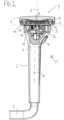
- Fig. 1
- die Armlehne (Längsschnitt),
- Fig. 2
- die Armlehne (Querschnitt),
- Fig. 3
- Teile der Armauflage und des Drehmechanismus,
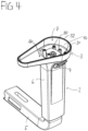
- Fig. 4
- die Armlehnenhülse ohne Drehmechanismus,
- Fig. 5
- die Armlehnenhülse mit Drehmechanismus,
- Fig. 6
- die Armlehne ohne Auflagekörper.
- Sämtliche Figuren zeigen die Erfindung nicht maßstabsgerecht, dabei lediglich schematisch und nur mit ihren wesentlichen Bestandteilen. Gleiche Bezugszeichen entsprechen dabei Elementen gleicher oder vergleichbarer Funktion. Die
Fig. 3 und4 , miteinander kombiniert, zeigen eine Explosionsdarstellung der inFig. 6 dargestellten Armlehne ohne Auflagekörper. - Wie in den
Fig. 1 bis 5 dargestellt, umfaßt die Armlehne 1 eine höhenverstellbare, insbesondere teleskopartig aufgebaute Armlehnensäule 2, deren Außenhülse 6 an ihrem oberen Ende gegenüber dem eigentlichen Säulenteil aufgeweitet ist und auf diese Weise einen Lagerkopf 3 für eine Armauflage 9 bildet. Die nach oben geöffnete, jedenfalls aber über eine ausreichend große Öffnung 7 verfügende Außenhülse 6 der Armlehnensäule 2 wird durch die Armauflage 9 nach Art eines Deckels verschlossen. Wie weiter unten genauer beschrieben, kann die Armauflage 9 relativ zu der Armlehnensäule 2 um eine vertikale Drehachse 8 gedreht und in Armauflagenlängsrichtung 21 gegenüber der Armlehnensäule 2 linear verschoben werden. Dabei liegt die Armauflage 9 während beider Bewegungen auf dem Rand 52 der Öffnung 7 der Armlehnensäule 2 auf. Der Öffnungsrand 52 und die Unterseite 40 der Armauflage 9 begrenzen damit zugleich den Innenraum 10 der Armlehnensäule 2 nach oben. - Für die Höhenverstellung der Armlehne 1 ist ein Betätigungsknopf 4 vorgesehen, der durch ein zur Außenseite hin offenen Durchbruch der Armlehnensäule 2 ragt. Die Armlehnensäule 2 ist mit Hilfe eines an ihrem unteren Fußende waagerecht herausführenden Armlehnenträgers 5 an dem Unterbau des Bürostuhls (nicht abgebildet) befestigbar. Die Angaben "hinten/vorn" bzw. "oben/unten" bzw. "senkrecht/waagerecht" usw. beziehen sich auf den normalen Benutzungszustand des Bürostuhls.
- Die Armauflage 9 umfaßt einen Basisträger 11 und einen mit dem Basisträger 11 lösbar verbundenen Auflagekörper 12. Basisträger 11 und Auflagekörper 12 können dabei beispielsweise unter Ausbildung einer Schraub-, Rast-, Schnapp- oder Klemmverbindung miteinander verbunden sein. In dem Basisträger 11 der Armauflage 9 ist ein in Armauflagenlängsrichtung 21 verlaufender Führungsschlitz 31 vorgesehen. Dieser dient zur Bereitstellung einer Kulissenführung zur linearen Verschiebung der Armauflage 9 relativ zu der Armlehnensäule 2.
- Zwischen dem Basisträger 11 und dem Auflagekörper 12 ist als ein Übertragungs- bzw. Mitnehmer- oder Koppelelement eine Halteplatte 13 angeordnet. Im montierten Zustand liegt die Halteplatte 13 sowohl an der Oberseite 14 des Basisträgers 11 als auch an der Unterseite 15 des Auflagekörpers 12 an und ist mit dem Basisträger 11 und/oder dem Auflagekörper 12 derart verbunden, daß der mit diesen beiden Bauteilen eine Bewegungseinheit bildet.
- Die Länge der Halteplatte 13 (in Armauflagenlängsrichtung 21 gesehen) ist dabei größer als die Länge des Führungsschlitzes 31, so daß die Halteplatte 13 den Führungsschlitz 31 in allen Stellungen dieser beiden Bauteile zueinander zumindest teilweise abdeckt.
- In der Halteplatte 13 sind mittig, in Längsrichtung 21 voneinander beabstandet, zwei Öffnungen 34 zur Aufnahme von Sicherungsschrauben 32 vorgesehen, welche zur Verbindung der Armauflage 9 mit der Armlehnensäule 2 die Halteplatte 13 mit zwei Kulissensteinen 36 verbinden, die mit ihren Hälsen 37 den Führungsschlitz 31 durchragen. Die Hälse 37 liegen mit anderen Worten als Führungselemente in dem Führungsschlitz 31 ein.
- Die als Führungs- bzw. Kraftübertragungselemente der Armauflage 9 dienenden, in Form von Führungszapfen ausgebildeten Kulissensteine 36 sind Teile eines Drehstücks 23 eines in der Armlehnensäule 2 angeordneten Drehlagers 22, das den für die Rotation der Armauflage 9 erforderlichen Drehmechanismus bereitstellt. Neben dem Drehstück 23 umfaßt das Drehlager 22 Mittel zum Lagern des Drehstücks 23.
- In dem illustrierten Beispiel liegt das kreiszylinderförmige Drehstück 23 in einer entsprechend dimensionierten, zum Stützen und Führen des Drehstücks 23 ausgebildeten Lagerbuchse 24 ein. Die Lagerbuchse 24 ist topfförmig mit Boden 25 und Wand 26 ausgeführt.
- In dem Boden 25 der Lagerbuchse 24 ist mittig eine domartig erhöhte Gleitlagerstelle 38 vorgesehen, die mit einer am Drehstück 23, dort ebenfalls mittig vorgesehenen Gleitlagerstelle 39 zusammenwirkt. Zusätzlich wird die Lage des Drehstücks 23 in der Lagerbuchse 24 mit Hilfe einer Sicherungsschraube 33 gesichert. Zu diesem Zweck ist das Drehstück 23 mittig mit einer Öffnung 35 versehen, durch die hindurch die Sicherungsschraube 33 geführt und in ein entsprechend in der Mitte der Gleitlagerstelle 38 der Lagerbuchse 24 vorgesehene Gewindeöffnung 41 geschraubt werden kann.
- Der durch die Lagerstellen 38, 39 definierte Ort der Drehachse 8 ist mit Blick auf die Benutzung der Armlehne 1 aus ergonomischen Gründen zu der Mittellängsachse 18 der Armlehnensäule 2, die in dem hier gezeigten Beispiel schräg zur Vertikalen verläuft, versetzt angeordnet.
- Die Lagerbuchse 24 oder ein anderes geeignetes Mittel zum Lagern des Drehstücks 23 kann als integrierter Teil der Armlehnensäule 2 ausgebildet sein. So kann die Lagerbuchse 24 beispielsweise an die Armlehnensäule 2 angespritzt oder auf andere Weise einteilig mit der Armlehnensäule 2 verbunden sein. Die Lagerbuchse 24 oder ein anderes geeignetes Lagermittel kann aber auch, wie in dem illustrierten Beispiel, als separates Bauteil ausgeführt sein. In diesem Fall muß die Lagerbuchse 24 mit der Armlehnensäule 2 hinreichend fest verbunden sein. Im dargestellten Beispiel ist die Lagerbuchse 24 zu diesem Zweck mit einer Montageplatte 27 versehen, die sich einseitig an die Lagerbuchse 24 anschließt und den Boden 25 der Lagerbuchse 24 nach einer Seite hin verlängert. Die Montageplatte 27 weist Öffnungen 28 für Montageschrauben 29 auf, mit denen das Drehlager 22 mit entsprechend ausgeführten Verbindungsstellen 30 der Armlehnensäule 2 verbunden wird.
- Im montierten Zustand liegt die Lagerbuchse 24 mit ihrer Unterseite 16 an der der Montageplatte 27 gegenüberliegenden Seite auf einem Stützabschnitt 17 der Armlehnensäule 2 auf, der durch die Aufweitung der Außenhülse 6 bereitgestellt wird. Dadurch wird eine besonders stabile Montage des Drehlagers 22 in der Armlehnensäule 2 erreicht.
- Die domartig ausgeführten Kulissensteine 36 sind, zusammen mit dem Mittelteil 19, das die Gleitlagerstelle 39 ausbildet und zugleich auch die Öffnung 35 aufweist, einstückig ausgebildet. Diese Mittelteil 19 liegt in einer dafür vorgesehenen Aufnahme des Grundkörpers 56 des Drehstücks 23 ein. Die Kulissensteine 36 ragen aus diesem Grundkörper 56 vertikal nach oben in die endseitige Öffnung 7 der Außenhülse 6 hinein.
- Mit ihren Enden ragen die Kulissensteine 36 über den Rand 52 der Öffnung 7 der Armlehnensäule 2 hinaus in die Armauflage 9 hinein, so daß nicht von einer tatsächlich vollständigen Anordnung des Drehmechanismus im Innenraum 10 der Armlehnensäule 2 gesprochen werden kann. Richtigerweise ist der Drehmechanismus daher lediglich "im wesentlichen vollständig" in der Armlehnensäule 2 aufgenommen.
- Da die Lagerbuchse 24 fest mit der Armlehnensäule 2 verbunden ist, ist eine lineare Verschiebung der Armauflage 9 in Armauflagenlängsrichtung 21 möglich, indem die über die Halteplatte 13 und die Kulissensteine 36 mit dem Drehlager 22 verbundene Armauflage 9 in Armauflagenlängsrichtung 21 relativ zu der Armlehnensäule 2 bewegt wird.
- Unabhängig von einer solchen Linearbewegung der Armauflage 9 ist eine Drehung der Armauflage 9 um die von dem Drehlager 22 festgelegte vertikale Drehachse 8 der Armlehne 1 möglich, indem die Armauflage 9 bei ihrer Beaufschlagung mit einer nicht in Armauflagenlängsrichtung 21 wirkenden Kraft relativ zu der Armlehnensäule 2 bewegt wird. Sowohl die Linearbewegung als auch Drehbewegung der Armauflage 9 sind unabhängig voneinander, auch gleichzeitig ausführbar.
- Der Rand 52 der Öffnung 7 definiert eine horizontale Trennebene (in den
Fig. 1 und2 mit einer durchbrochenen Linie angedeutet), welche eine obere Armlehnenbaugruppe, umfassend die Armauflage 9, und eine untere Armlehnenbaugruppe, umfassend die Armlehnensäule 2, voneinander trennt. Dabei ist der Drehmechanismus, hier also das Drehlager 22 mit Lagerbuchse 24 und Drehstück 23, Teil der unteren Armlehnenbaugruppe, während die obere Armlehnenbaugruppe relativ zu der unteren Armlehnenbaugruppe von dem Drehmechanismus gedreht werden kann. - Der Drehmechanismus ist ein Teil einer Baugruppe, die sich dadurch auszeichnet, daß weder diese Baugruppe insgesamt, noch Teile dieser Baugruppe laterale Bewegungen innerhalb einer horizontalen Raumebene ausführen können; diese Baugruppe insgesamt kann weder eine Linearbewegung noch eine Drehbewegung ausführen.
- Sowohl die Linearbewegung als auch Drehbewegung der Armauflage 9 sind in einer besonders bevorzugten Ausführung der Erfindung mit geeigneten Stellungs- bzw. Bedienmitteln kontrollierbar.
- So ist hinsichtlich der Längsverstellung der Armauflage 9 vorzugsweise vorgesehen, daß die Montageplatte 13 über eine Rastnase 42 verfügt, die im Montagezustand in am Basisträger 11 vorgesehene Rastausnehmungen 43 eingreifend ein Rastgesperre, vorzugsweise ein Schubrastgesperre mit Reibungseingriff, ausbildet. Die Rastnase 42 dient dabei als Rastsperrer und die Rastausnehmungen 43 dienen als Rastnuten, die eine Anzahl von in Längsrichtung 21 der Armauflage 9 angeordneten Raststellungen definieren. Bei dem sich dadurch ergebenden beiderseitig kraftschlüssigem Gesperre entsteht in den Raststellungen lediglich ein erhöhter Widerstand gegen die Bewegung, der durch eine entsprechend erhöhte Kraft überwunden werden kann. Bei einer mit gleichmäßiger Kraft erfolgenden Bewegung findet die Armauflage 9 daher in den betreffenden Stellungen Ruhe- oder Raststellungen.
- Die vorzugsweise selbstfedernde, insbesondere durch ein Federelement gebildete, beispielsweise aus Federstahl gefertigte Rastnase 42 ist dabei in eine der Längskanten 20 der Halteplatte 13 integriert, die zu diesem Zweck eine zur Aufnahme des Federelements geeignete Aufnahmeöffnung 44 aufweist. Die Rastnase 42 ragt im montierten Zustand quer zu der Armauflagenlängsrichtung 21 aus der Halteplatte 13 heraus. Die Rastausnehmungen 43 sind unmittelbar benachbart zu einander auf der Höhe des Führungsschlitzes 31 auf der Oberseite 14 des Basisträgers 11 angeordnet, und zwar in Gestalt einer parallel zu dem Führungsschlitz 31 liegenden Leiste 45, in dem hier dargestellten Beispiel als integrierter Teil einer Verstrebung an der Basisträgeroberseite 14. In einer abweichenden Ausführung kann die Rastnase 42 auch einteilig mit der Halteplatte 13 ausgebildet sein.
- Hinsichtlich der Drehverstellung der Armauflage 9 ist es vorzugsweise vorgesehen, die Innenseite 46 der Wand 26 der Lagerbuchse 24 entlang eines dem vorgesehenen Drehwinkel entsprechenden Wandsegmentes mit entsprechenden Rastausnehmungen 47 auszustatten und an dem Drehstück 23 ein Rastelement 48 anzubringen, das im Montagezustand in die Rastausnehmungen 47 eingreifend ein Rastgesperre, vorzugsweise ein Schubrastgesperre mit Reibungseingriff, ausbildet, so wie dies auch hinsichtlich der Längsverstellung beschrieben wurde. Bei dem Rastelement 48 handelt es sich in diesem Fall um einen federbelasteten Rastzylinder aus einem nichtfedernden Material, der in einer an der Außenseite 49 des Drehstücks 23 ausgebildeten Aufnahmetasche 50 im Drehstück 22 einliegt. Das Rastelement 48 wird mit Hilfe eines ebenfalls in der Aufnahmetasche 50 einliegenden Federelements 51 gegen die Rastausnehmungen 47 gedrückt. Anstelle einer solchen Kombination aus Rastelement 48 und Federelement 51 kann auch für die Rasteinrichtung der Drehverstellung ein selbstfederndes Rastelement vorgesehen sein.
- Bei beiden Rasteinrichtungen können die Anzahl der Raststufen entsprechend dem Verstellweg gewählt werden. Durch eine geeignete Materialauswahl kann der bei der Verstellung zu überwindende Widerstand und damit die Stärke des haptischen Feedbacks sowie, sofern gewünscht, auch die Lautstärke eines akustischen Feedbacks eingestellt werden.
- Der maximale Drehwinkel des Drehstücks 23 wird durch Anschläge festgelegt. Zu diesem Zweck ist in der Wand 26 der Lagerbuchse 25 eine Ausnehmung 53 vorgesehen, in die ein am Grundkörper 56 des Drehstücks 23 radial nach außen ragender Bewegungsbegrenzer 54 hineinragt. Beim Erreichen der maximal möglichen Drehung schlägt der Begrenzer 54 an den vertikalen Rändern 55 der Ausnehmung 53 an.
-
- 1
- Armlehne
- 2
- Armlehnensäule
- 3
- Lagerkopf
- 4
- Betätigungsknopf
- 5
- Armlehnenträger
- 6
- Außenhülse
- 7
- Öffnung
- 8
- Drehachse
- 9
- Armauflage
- 10
- Innenraum
- 11
- Basisträger
- 12
- Auflagekörper
- 13
- Halteplatte
- 14
- Oberseite des Basisträgers
- 15
- Unterseite des Auflagekörpers
- 16
- Unterseite der Lagerbuchse
- 17
- Stützabschnitt
- 18
- Mittellängsachse
- 19
- Mittelteil des Drehstücks
- 20
- Längskante
- 21
- Armauflagenlängsrichtung
- 22
- Drehlager
- 23
- Drehstück
- 24
- Lagerbuchse
- 25
- Boden
- 26
- Wand
- 27
- Montageplatte
- 28
- Öffnung
- 29
- Montageschraube
- 30
- Verbindungsstelle
- 31
- Führungsschlitz
- 32
- Sicherungsschraube
- 33
- Sicherungsschraube
- 34
- Öffnung
- 35
- Öffnung
- 36
- Kulissenstein
- 37
- Hals
- 38
- Gleitlagerstelle
- 39
- Gleitlagerstelle
- 40
- Unterseite der Armauflage
- 41
- Gewindeöffnung
- 42
- Rastnase
- 43
- Rastausnehmung
- 44
- Aufnahme
- 45
- Leiste
- 46
- Wandinnenseite
- 47
- Rastausnehmung
- 48
- Rastelement
- 49
- Außenseite des Drehstücks
- 50
- Aufnahmetasche
- 51
- Federelement
- 52
- Öffnungsrand
- 53
- Ausnehmung
- 54
- Begrenzer
- 55
- Anschlagsrand
- 56
- Grundkörper
Claims (6)
- Armlehne (1), insbesondere für einen Bürostuhl, mit einer Armlehnensäule (2), mit einer auf der Armlehnensäule (2) gelagerten, um eine Drehachse (8) drehbaren Armauflage (9), die relativ zu der Armlehnensäule (2) linear verschiebbar ist, wobei der Drehmechanismus zur Drehung der Armauflage (9) im wesentlichen vollständig innerhalb der Armlehnensäule (2) angeordnet ist, wobei die Armauflage (9) mit der Armlehnensäule (2) mit Hilfe einer Kulissenführung (31, 36) linear verschiebbar verbunden ist, wobei die Kulissenführung einen an der Unterseite (40) der Armauflage (9) vorgesehenen Führungsschlitz (31) und zwei gleichzeitig wirkende Führungselemente (36) aufweist, die durch den Führungsschlitz (31) greifen, wobei der Drehmechanismus ein Drehlager (22) umfaßt und die Führungselemente (36) der Kulissenführung an einem Drehstück (23) des Drehlagers (22) befestigt sind.
- Armlehne (1) nach Anspruch 1, wobei der Drehmechanismus zur Drehung der Armauflage (9) im wesentlichen vollständig innerhalb eines Innenraumes der Armlehnensäule (2) angeordnet ist, welcher Innenraum (10) von der Armauflage (9) nach Art eines Deckels verschlossen wird.
- Armlehne (1) nach Anspruch 1 oder 2,- wobei die Armauflage (9) einen Basisträger (11) und einen mit dem Basisträger (11) vorzugsweise lösbar verbundenen Auflagekörper (12) umfaßt,- wobei in dem Basisträger (11) ein in Armauflagenlängsrichtung (21) verlaufender Führungsschlitz (31) vorgesehen ist, und- wobei zwischen dem Basisträger (11) und dem Auflagekörper (12) eine Halteplatte (13) angeordnet ist, die mit dem Basisträger (11) und/oder dem Auflagekörper (12) eine Bewegungseinheit bildet.
- Armlehne (1) nach Anspruch 3, wobei die Halteplatte (13) den Führungsschlitz (31) zumindest teilweise abdeckt.
- Armlehne (1) nach einem der Ansprüche 1 bis 4, wobei die Armauflage (9) auf dem Rand (52) der Öffnung (7) der Armlehnensäule (2) aufliegt.
- Stuhl, insbesondere Bürostuhl, mit einer Armlehne (1) nach einem der Ansprüche 1 bis 5.
Applications Claiming Priority (1)
| Application Number | Priority Date | Filing Date | Title |
|---|---|---|---|
| DE102020101309.4A DE102020101309A1 (de) | 2020-01-21 | 2020-01-21 | Armlehne, insbesondere für einen Bürostuhl |
Publications (2)
| Publication Number | Publication Date |
|---|---|
| EP3854263A1 EP3854263A1 (de) | 2021-07-28 |
| EP3854263B1 true EP3854263B1 (de) | 2025-07-02 |
Family
ID=74186444
Family Applications (1)
| Application Number | Title | Priority Date | Filing Date |
|---|---|---|---|
| EP21000008.9A Active EP3854263B1 (de) | 2020-01-21 | 2021-01-14 | Armlehne, insbesondere für einen bürostuhl |
Country Status (4)
| Country | Link |
|---|---|
| US (1) | US11369204B2 (de) |
| EP (1) | EP3854263B1 (de) |
| CN (1) | CN113208339A (de) |
| DE (1) | DE102020101309A1 (de) |
Families Citing this family (4)
| Publication number | Priority date | Publication date | Assignee | Title |
|---|---|---|---|---|
| US11324326B2 (en) * | 2020-03-03 | 2022-05-10 | Yi-Ru Chen | Multi-directional adjustable armrest pad and chair armrest device with armrest pad |
| JP7777578B2 (ja) * | 2020-07-22 | 2025-11-28 | フォームウェイ ファーニチャー リミティド | 椅子用のアーム組立体 |
| US11787063B2 (en) * | 2020-09-11 | 2023-10-17 | Verb Surgical Inc. | Linear lock and adjustable arm support system |
| TWI761158B (zh) * | 2021-03-30 | 2022-04-11 | 廣力達企業有限公司 | 配組式椅扶手 |
Citations (1)
| Publication number | Priority date | Publication date | Assignee | Title |
|---|---|---|---|---|
| US20180020834A1 (en) * | 2016-07-22 | 2018-01-25 | Pao Shen Enterprises Co., Ltd. | Armrest Assembly for a Chair |
Family Cites Families (16)
| Publication number | Priority date | Publication date | Assignee | Title |
|---|---|---|---|---|
| US5647638A (en) * | 1995-06-07 | 1997-07-15 | Haworth, Inc. | Height-adjustable chair arm assembly |
| IT1320404B1 (it) * | 2000-06-06 | 2003-11-26 | Pro Cord Srl | Bracciolo per sedia, poltrona o simile, e sedia utilizzante talebracciolo. |
| ES2252372T3 (es) * | 2002-10-04 | 2006-05-16 | Sedus Stoll Ag | Reposabrazos. |
| US6908158B2 (en) * | 2003-01-02 | 2005-06-21 | Haworth, Inc. | Lateral motion chair arm mechanism for chair arm |
| US7066546B2 (en) * | 2003-12-30 | 2006-06-27 | Hni Technologies Inc. | Horizontally adjustable chair armrest |
| US6948775B2 (en) * | 2004-02-20 | 2005-09-27 | Po-Chuan Tsai | Office chair armrest |
| US7188907B1 (en) * | 2005-05-24 | 2007-03-13 | Yu-Shan Lai | Armrest assembly having a position adjusting function |
| US7387341B1 (en) * | 2007-03-16 | 2008-06-17 | Po-Chuan Tsai | Armrest having position adjusting function |
| WO2009018402A1 (en) * | 2007-08-01 | 2009-02-05 | Hni Technologies Inc. | Adjustable arm rest for a chair |
| DE102007060327B4 (de) * | 2007-12-12 | 2012-04-12 | Sedus Stoll Ag | Horizontal verstellbare Armlehne und Stuhl mit einer solchen Armlehne |
| US20110254340A1 (en) * | 2010-04-20 | 2011-10-20 | Tsai Hsuan-Chin | Reversing Assembly for Office Chair Armrest |
| US8474914B2 (en) * | 2010-07-30 | 2013-07-02 | Atec International Team Co., Ltd. | Armrest adjustment device |
| DE102016002789A1 (de) * | 2016-03-07 | 2017-09-07 | Hilde Filip | Verstellbare Armstütze, insbesondere für eine Sitzvorrichtung |
| DE102017110492A1 (de) * | 2017-05-15 | 2018-11-15 | Bock 1 Gmbh & Co. Kg | Armlehne, insbesondere für einen Bürostuhl |
| IT201900014490A1 (it) * | 2019-08-09 | 2021-02-09 | Brado S P A | Dispositivo di regolazione della posizione di un bracciolo di una sedia. |
| TWI702022B (zh) * | 2019-10-29 | 2020-08-21 | 堡勝企業股份有限公司 | 旋轉定位機構、扶手座可旋轉的扶手架及椅子 |
-
2020
- 2020-01-21 DE DE102020101309.4A patent/DE102020101309A1/de active Pending
-
2021
- 2021-01-14 EP EP21000008.9A patent/EP3854263B1/de active Active
- 2021-01-19 CN CN202110066397.4A patent/CN113208339A/zh active Pending
- 2021-01-21 US US17/154,084 patent/US11369204B2/en active Active
Patent Citations (1)
| Publication number | Priority date | Publication date | Assignee | Title |
|---|---|---|---|---|
| US20180020834A1 (en) * | 2016-07-22 | 2018-01-25 | Pao Shen Enterprises Co., Ltd. | Armrest Assembly for a Chair |
Also Published As
| Publication number | Publication date |
|---|---|
| US11369204B2 (en) | 2022-06-28 |
| CN113208339A (zh) | 2021-08-06 |
| DE102020101309A1 (de) | 2021-07-22 |
| EP3854263A1 (de) | 2021-07-28 |
| US20210219729A1 (en) | 2021-07-22 |
Similar Documents
| Publication | Publication Date | Title |
|---|---|---|
| EP3854263B1 (de) | Armlehne, insbesondere für einen bürostuhl | |
| EP3403535B1 (de) | Armlehne, insbesondere für einen bürostuhl | |
| EP1941815B1 (de) | Bewegungsgekoppelte Servoeinrichtung für ein Sitzteil, insbesondere eines Stuhls | |
| EP1971245B1 (de) | Permanentkontaktmechanik | |
| EP0687787B1 (de) | Scharniereinrichtung | |
| DE10116821B4 (de) | Verstellbare Armlehnenanordnung mit einem einzigen Verstellhebel | |
| EP2611673B1 (de) | Lenksäule für ein kraftfahrzeug | |
| EP0079530A2 (de) | Arretierbare Wippvorrichtung für Sitzteile von Sitzmöbeln | |
| EP3120732B1 (de) | Mechanik für einen bürostuhl | |
| EP3225133B1 (de) | Höhenverstellbare armlehne | |
| EP2092850A1 (de) | Beschlag für einen Eckschrank | |
| EP2921077B1 (de) | Bürostuhl | |
| DE69202911T2 (de) | Verstellbarer Stuhl. | |
| DE10126000A1 (de) | Synchronmechanik für die simultane Sitzflächen- und Rückenlehnen-Schwenkbewegung bei Bürostühlen | |
| EP0372398A2 (de) | Stehpult | |
| EP1126114B1 (de) | Verstellbares Scharnier | |
| DE4436199C1 (de) | Radiusbetätiger für Sicherheitsschalter | |
| DE102005026792A1 (de) | Oberwalzen-Trag- und Belastungsarm | |
| DE202010010115U1 (de) | Mechanik für einen Bürostuhl | |
| EP1566118B1 (de) | Vorrichtung zur Stützung der Wirbelsäule | |
| EP3403534B1 (de) | Sitzvorrichtung | |
| EP0593881A1 (de) | Sitzträger für Sitzmöbel | |
| DE202022105640U1 (de) | Mehrteiliger Armlehnenträger | |
| EP3865007A1 (de) | Armlehne, insbesondere für einen bürostuhl | |
| DE102022125799A1 (de) | Mehrteiliger Armlehnenträger |
Legal Events
| Date | Code | Title | Description |
|---|---|---|---|
| PUAI | Public reference made under article 153(3) epc to a published international application that has entered the european phase |
Free format text: ORIGINAL CODE: 0009012 |
|
| STAA | Information on the status of an ep patent application or granted ep patent |
Free format text: STATUS: THE APPLICATION HAS BEEN PUBLISHED |
|
| AK | Designated contracting states |
Kind code of ref document: A1 Designated state(s): AL AT BE BG CH CY CZ DE DK EE ES FI FR GB GR HR HU IE IS IT LI LT LU LV MC MK MT NL NO PL PT RO RS SE SI SK SM TR |
|
| STAA | Information on the status of an ep patent application or granted ep patent |
Free format text: STATUS: REQUEST FOR EXAMINATION WAS MADE |
|
| 17P | Request for examination filed |
Effective date: 20220124 |
|
| RBV | Designated contracting states (corrected) |
Designated state(s): AL AT BE BG CH CY CZ DE DK EE ES FI FR GB GR HR HU IE IS IT LI LT LU LV MC MK MT NL NO PL PT RO RS SE SI SK SM TR |
|
| STAA | Information on the status of an ep patent application or granted ep patent |
Free format text: STATUS: EXAMINATION IS IN PROGRESS |
|
| 17Q | First examination report despatched |
Effective date: 20230421 |
|
| GRAP | Despatch of communication of intention to grant a patent |
Free format text: ORIGINAL CODE: EPIDOSNIGR1 |
|
| STAA | Information on the status of an ep patent application or granted ep patent |
Free format text: STATUS: GRANT OF PATENT IS INTENDED |
|
| GRAJ | Information related to disapproval of communication of intention to grant by the applicant or resumption of examination proceedings by the epo deleted |
Free format text: ORIGINAL CODE: EPIDOSDIGR1 |
|
| STAA | Information on the status of an ep patent application or granted ep patent |
Free format text: STATUS: EXAMINATION IS IN PROGRESS |
|
| INTG | Intention to grant announced |
Effective date: 20241220 |
|
| GRAP | Despatch of communication of intention to grant a patent |
Free format text: ORIGINAL CODE: EPIDOSNIGR1 |
|
| STAA | Information on the status of an ep patent application or granted ep patent |
Free format text: STATUS: GRANT OF PATENT IS INTENDED |
|
| INTC | Intention to grant announced (deleted) | ||
| INTG | Intention to grant announced |
Effective date: 20250129 |
|
| GRAS | Grant fee paid |
Free format text: ORIGINAL CODE: EPIDOSNIGR3 |
|
| GRAA | (expected) grant |
Free format text: ORIGINAL CODE: 0009210 |
|
| STAA | Information on the status of an ep patent application or granted ep patent |
Free format text: STATUS: THE PATENT HAS BEEN GRANTED |
|
| P01 | Opt-out of the competence of the unified patent court (upc) registered |
Free format text: CASE NUMBER: APP_23721/2025 Effective date: 20250519 |
|
| AK | Designated contracting states |
Kind code of ref document: B1 Designated state(s): AL AT BE BG CH CY CZ DE DK EE ES FI FR GB GR HR HU IE IS IT LI LT LU LV MC MK MT NL NO PL PT RO RS SE SI SK SM TR |
|
| REG | Reference to a national code |
Ref country code: GB Ref legal event code: FG4D Free format text: NOT ENGLISH |
|
| REG | Reference to a national code |
Ref country code: CH Ref legal event code: EP |
|
| REG | Reference to a national code |
Ref country code: DE Ref legal event code: R096 Ref document number: 502021007876 Country of ref document: DE |
|
| REG | Reference to a national code |
Ref country code: IE Ref legal event code: FG4D Free format text: LANGUAGE OF EP DOCUMENT: GERMAN |
|
| REG | Reference to a national code |
Ref country code: NL Ref legal event code: MP Effective date: 20250702 |
|
| PG25 | Lapsed in a contracting state [announced via postgrant information from national office to epo] |
Ref country code: PT Free format text: LAPSE BECAUSE OF FAILURE TO SUBMIT A TRANSLATION OF THE DESCRIPTION OR TO PAY THE FEE WITHIN THE PRESCRIBED TIME-LIMIT Effective date: 20251103 |
|
| PG25 | Lapsed in a contracting state [announced via postgrant information from national office to epo] |
Ref country code: NL Free format text: LAPSE BECAUSE OF FAILURE TO SUBMIT A TRANSLATION OF THE DESCRIPTION OR TO PAY THE FEE WITHIN THE PRESCRIBED TIME-LIMIT Effective date: 20250702 |
|
| PG25 | Lapsed in a contracting state [announced via postgrant information from national office to epo] |
Ref country code: IS Free format text: LAPSE BECAUSE OF FAILURE TO SUBMIT A TRANSLATION OF THE DESCRIPTION OR TO PAY THE FEE WITHIN THE PRESCRIBED TIME-LIMIT Effective date: 20251102 |
|
| PGFP | Annual fee paid to national office [announced via postgrant information from national office to epo] |
Ref country code: GB Payment date: 20251202 Year of fee payment: 6 |
|
| PG25 | Lapsed in a contracting state [announced via postgrant information from national office to epo] |
Ref country code: NO Free format text: LAPSE BECAUSE OF FAILURE TO SUBMIT A TRANSLATION OF THE DESCRIPTION OR TO PAY THE FEE WITHIN THE PRESCRIBED TIME-LIMIT Effective date: 20251002 |
|
| REG | Reference to a national code |
Ref country code: LT Ref legal event code: MG9D |
|
| PG25 | Lapsed in a contracting state [announced via postgrant information from national office to epo] |
Ref country code: FI Free format text: LAPSE BECAUSE OF FAILURE TO SUBMIT A TRANSLATION OF THE DESCRIPTION OR TO PAY THE FEE WITHIN THE PRESCRIBED TIME-LIMIT Effective date: 20250702 |
|
| PG25 | Lapsed in a contracting state [announced via postgrant information from national office to epo] |
Ref country code: HR Free format text: LAPSE BECAUSE OF FAILURE TO SUBMIT A TRANSLATION OF THE DESCRIPTION OR TO PAY THE FEE WITHIN THE PRESCRIBED TIME-LIMIT Effective date: 20250702 |
|
| PG25 | Lapsed in a contracting state [announced via postgrant information from national office to epo] |
Ref country code: GR Free format text: LAPSE BECAUSE OF FAILURE TO SUBMIT A TRANSLATION OF THE DESCRIPTION OR TO PAY THE FEE WITHIN THE PRESCRIBED TIME-LIMIT Effective date: 20251003 |
|
| PG25 | Lapsed in a contracting state [announced via postgrant information from national office to epo] |
Ref country code: SE Free format text: LAPSE BECAUSE OF FAILURE TO SUBMIT A TRANSLATION OF THE DESCRIPTION OR TO PAY THE FEE WITHIN THE PRESCRIBED TIME-LIMIT Effective date: 20250702 Ref country code: CZ Free format text: LAPSE BECAUSE OF FAILURE TO SUBMIT A TRANSLATION OF THE DESCRIPTION OR TO PAY THE FEE WITHIN THE PRESCRIBED TIME-LIMIT Effective date: 20250702 |
|
| PG25 | Lapsed in a contracting state [announced via postgrant information from national office to epo] |
Ref country code: LV Free format text: LAPSE BECAUSE OF FAILURE TO SUBMIT A TRANSLATION OF THE DESCRIPTION OR TO PAY THE FEE WITHIN THE PRESCRIBED TIME-LIMIT Effective date: 20250702 |
|
| PG25 | Lapsed in a contracting state [announced via postgrant information from national office to epo] |
Ref country code: PL Free format text: LAPSE BECAUSE OF FAILURE TO SUBMIT A TRANSLATION OF THE DESCRIPTION OR TO PAY THE FEE WITHIN THE PRESCRIBED TIME-LIMIT Effective date: 20250702 Ref country code: BG Free format text: LAPSE BECAUSE OF FAILURE TO SUBMIT A TRANSLATION OF THE DESCRIPTION OR TO PAY THE FEE WITHIN THE PRESCRIBED TIME-LIMIT Effective date: 20250702 |
|
| PG25 | Lapsed in a contracting state [announced via postgrant information from national office to epo] |
Ref country code: RS Free format text: LAPSE BECAUSE OF FAILURE TO SUBMIT A TRANSLATION OF THE DESCRIPTION OR TO PAY THE FEE WITHIN THE PRESCRIBED TIME-LIMIT Effective date: 20251002 |
|
| PG25 | Lapsed in a contracting state [announced via postgrant information from national office to epo] |
Ref country code: ES Free format text: LAPSE BECAUSE OF FAILURE TO SUBMIT A TRANSLATION OF THE DESCRIPTION OR TO PAY THE FEE WITHIN THE PRESCRIBED TIME-LIMIT Effective date: 20250702 |
|
| PG25 | Lapsed in a contracting state [announced via postgrant information from national office to epo] |
Ref country code: SM Free format text: LAPSE BECAUSE OF FAILURE TO SUBMIT A TRANSLATION OF THE DESCRIPTION OR TO PAY THE FEE WITHIN THE PRESCRIBED TIME-LIMIT Effective date: 20250702 |
|
| PG25 | Lapsed in a contracting state [announced via postgrant information from national office to epo] |
Ref country code: DK Free format text: LAPSE BECAUSE OF FAILURE TO SUBMIT A TRANSLATION OF THE DESCRIPTION OR TO PAY THE FEE WITHIN THE PRESCRIBED TIME-LIMIT Effective date: 20250702 |
|
| PGFP | Annual fee paid to national office [announced via postgrant information from national office to epo] |
Ref country code: DE Payment date: 20260112 Year of fee payment: 6 |
|
| PGFP | Annual fee paid to national office [announced via postgrant information from national office to epo] |
Ref country code: IT Payment date: 20260120 Year of fee payment: 6 |
|
| PG25 | Lapsed in a contracting state [announced via postgrant information from national office to epo] |
Ref country code: SK Free format text: LAPSE BECAUSE OF FAILURE TO SUBMIT A TRANSLATION OF THE DESCRIPTION OR TO PAY THE FEE WITHIN THE PRESCRIBED TIME-LIMIT Effective date: 20250702 Ref country code: EE Free format text: LAPSE BECAUSE OF FAILURE TO SUBMIT A TRANSLATION OF THE DESCRIPTION OR TO PAY THE FEE WITHIN THE PRESCRIBED TIME-LIMIT Effective date: 20250702 |