EP3854340B1 - Dispositif d'aide à l'implantation d'une vis osseuse dans le milieu osseux d'un être vivant - Google Patents
Dispositif d'aide à l'implantation d'une vis osseuse dans le milieu osseux d'un être vivant Download PDFInfo
- Publication number
- EP3854340B1 EP3854340B1 EP21315006.3A EP21315006A EP3854340B1 EP 3854340 B1 EP3854340 B1 EP 3854340B1 EP 21315006 A EP21315006 A EP 21315006A EP 3854340 B1 EP3854340 B1 EP 3854340B1
- Authority
- EP
- European Patent Office
- Prior art keywords
- rod
- mandrel rod
- barrel
- screw
- mandrel
- Prior art date
- Legal status (The legal status is an assumption and is not a legal conclusion. Google has not performed a legal analysis and makes no representation as to the accuracy of the status listed.)
- Active
Links
Images

Classifications
-
- A—HUMAN NECESSITIES
- A61—MEDICAL OR VETERINARY SCIENCE; HYGIENE
- A61B—DIAGNOSIS; SURGERY; IDENTIFICATION
- A61B17/00—Surgical instruments, devices or methods
- A61B17/56—Surgical instruments or methods for treatment of bones or joints; Devices specially adapted therefor
- A61B17/58—Surgical instruments or methods for treatment of bones or joints; Devices specially adapted therefor for osteosynthesis, e.g. bone plates, screws or setting implements
- A61B17/88—Osteosynthesis instruments; Methods or means for implanting or extracting internal or external fixation devices
- A61B17/8875—Screwdrivers, spanners or wrenches
- A61B17/8886—Screwdrivers, spanners or wrenches holding the screw head
-
- A—HUMAN NECESSITIES
- A61—MEDICAL OR VETERINARY SCIENCE; HYGIENE
- A61B—DIAGNOSIS; SURGERY; IDENTIFICATION
- A61B17/00—Surgical instruments, devices or methods
- A61B17/56—Surgical instruments or methods for treatment of bones or joints; Devices specially adapted therefor
- A61B17/58—Surgical instruments or methods for treatment of bones or joints; Devices specially adapted therefor for osteosynthesis, e.g. bone plates, screws or setting implements
- A61B17/68—Internal fixation devices, including fasteners and spinal fixators, even if a part thereof projects from the skin
- A61B17/70—Spinal positioners or stabilisers, e.g. stabilisers comprising fluid filler in an implant
- A61B17/7074—Tools specially adapted for spinal fixation operations other than for bone removal or filler handling
- A61B17/7076—Tools specially adapted for spinal fixation operations other than for bone removal or filler handling for driving, positioning or assembling spinal clamps or bone anchors specially adapted for spinal fixation
- A61B17/7082—Tools specially adapted for spinal fixation operations other than for bone removal or filler handling for driving, positioning or assembling spinal clamps or bone anchors specially adapted for spinal fixation for driving, i.e. rotating, screws or screw parts specially adapted for spinal fixation, e.g. for driving polyaxial or tulip-headed screws
-
- A—HUMAN NECESSITIES
- A61—MEDICAL OR VETERINARY SCIENCE; HYGIENE
- A61B—DIAGNOSIS; SURGERY; IDENTIFICATION
- A61B17/00—Surgical instruments, devices or methods
- A61B17/56—Surgical instruments or methods for treatment of bones or joints; Devices specially adapted therefor
- A61B17/58—Surgical instruments or methods for treatment of bones or joints; Devices specially adapted therefor for osteosynthesis, e.g. bone plates, screws or setting implements
- A61B17/88—Osteosynthesis instruments; Methods or means for implanting or extracting internal or external fixation devices
- A61B17/8875—Screwdrivers, spanners or wrenches
-
- A—HUMAN NECESSITIES
- A61—MEDICAL OR VETERINARY SCIENCE; HYGIENE
- A61B—DIAGNOSIS; SURGERY; IDENTIFICATION
- A61B34/00—Computer-aided surgery; Manipulators or robots specially adapted for use in surgery
- A61B34/30—Surgical robots
-
- A—HUMAN NECESSITIES
- A61—MEDICAL OR VETERINARY SCIENCE; HYGIENE
- A61B—DIAGNOSIS; SURGERY; IDENTIFICATION
- A61B34/00—Computer-aided surgery; Manipulators or robots specially adapted for use in surgery
- A61B34/20—Surgical navigation systems; Devices for tracking or guiding surgical instruments, e.g. for frameless stereotaxis
- A61B2034/2046—Tracking techniques
- A61B2034/2055—Optical tracking systems
-
- A—HUMAN NECESSITIES
- A61—MEDICAL OR VETERINARY SCIENCE; HYGIENE
- A61B—DIAGNOSIS; SURGERY; IDENTIFICATION
- A61B90/00—Instruments, implements or accessories specially adapted for surgery or diagnosis and not covered by any of the groups A61B1/00 - A61B50/00, e.g. for luxation treatment or for protecting wound edges
- A61B90/36—Image-producing devices or illumination devices not otherwise provided for
- A61B90/37—Surgical systems with images on a monitor during operation
- A61B2090/374—NMR or MRI
-
- A—HUMAN NECESSITIES
- A61—MEDICAL OR VETERINARY SCIENCE; HYGIENE
- A61B—DIAGNOSIS; SURGERY; IDENTIFICATION
- A61B90/00—Instruments, implements or accessories specially adapted for surgery or diagnosis and not covered by any of the groups A61B1/00 - A61B50/00, e.g. for luxation treatment or for protecting wound edges
- A61B90/36—Image-producing devices or illumination devices not otherwise provided for
- A61B90/37—Surgical systems with images on a monitor during operation
- A61B2090/376—Surgical systems with images on a monitor during operation using X-rays, e.g. fluoroscopy
- A61B2090/3762—Surgical systems with images on a monitor during operation using X-rays, e.g. fluoroscopy using computed tomography systems [CT]
Definitions
- the present invention relates to devices for assisting in the implantation of bone screws in the bone environment of a living being, which find a particularly advantageous application in the field of spinal osteosynthesis, more particularly for the implantation of systems which allow the maintenance of two vertebrae, consecutive or not, relative to each other with a view to carrying out spinal arthrodesis with the aim, for example, of eliminating the cause of pain generated by a fracture of the vertebrae or to avoid the risk of paralytic complication linked to this fracture or even to treat a degenerative or tumoral pathology of the spinal column.
- the present invention aims to produce a device for assisting in the implantation of bone screws in the bone environment of a living being, which attempts to to limit as much as possible the risks of such an implantation by allowing the most secure implantation possible, which is as simple and inexpensive as possible to produce compared to similar devices known from the prior art, while facilitating the work of Practitioners.
- the present invention relates to a device for assisting in the implantation of a bone screw in a bone medium, in accordance with at least one of the appended claims.
- the invention relates to a device for assisting in the implantation of a bone screw 10 in a bone medium Os.
- Such a screw comprises a screw rod 11 defined along a screw axis 12 between a proximal end 13 and a distal end 14; a bone thread 15 made on the periphery of the screw rod 11, this bone thread having a pitch of determined value equal to Pa; a screw head 16 secured to the proximal end 13 of the screw rod, the distal end 14 of the screw rod having a configuration allowing it to penetrate by self-tapping into the bone medium Os.
- Such screws are well known in themselves.
- the device according to the invention comprises a barrel 20 defining a longitudinal axis 21, a cylindrical passage 22 of revolution made in the barrel 20 along the longitudinal axis 21, a tapping 23 made on the wall of the passage 22, the tapping 23 having a pitch of value Pa, and means 24 for fixing the barrel 20 to a reference point 25 linked to the bone medium Os.
- Mandrel rod 30 defined between a proximal end 31 and a distal end 32, the mandrel rod 30 having, on its lateral surface, at least one portion of cylindrical surface of revolution substantially complementary to the crossing 22, a thread 33 carried by the portion of cylindrical surface of revolution of the mandrel rod 30, the pitch of which is also of value Pa, so that the mandrel rod 30 is capable of being screwed into the tapping 23 of the barrel 20.
- the device further comprises means 35 for coupling the distal end 32 of the mandrel rod 30 with the screw head 16 so that the axis 12 of the screw rod 11 coincides with the longitudinal axis 21, and means 140 for controlling the rotation of the mandrel rod 30 relative to the barrel 20.
- the means 24 for fixing the barrel 20 to a reference point 25 they very preferably comprise an arm 124 or the like fixedly linked to the reference point 25, optionally articulated with a simple lock, and means 125 for securing the arm 124 to the barrel 20.
- the reference point 25 may consist of a point in the environment in which the patient is located who is to be treated as explained in the preamble to the description. This point may for example be linked, directly or indirectly, to the operating table on which the patient is immobilized.
- the device comprises a cylindrical through-hole 50 made in the mandrel rod 30, along the longitudinal axis 21, and a pin 51 whose cross-section is at most equal to the cross-section of the through-hole 50, the pin being capable of being inserted by sliding into this through-hole.
- Such a pin is also known in itself. It is often referred to by Practitioners as a “Kirschner pin”. These pins, generally made of stainless steel, sterilized, sharpened, small in diameter and smooth, are widely used in orthopedics to reduce fractures.
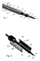
- the mandrel rod 30 has a 70 side through window, Figures 2 and 3 , made in its wall, this lateral through window 70 being able to connect the exterior of the mandrel rod with the through hole 50, the pin 51 then being able to be plugged into the through hole 50 via this lateral through window due to its natural elastic flexibility.
- the means 35 for coupling the distal end 32 of the mandrel rod 30 with the screw head 16 are very advantageously constituted by a through-hole 40 made in the mandrel rod 30, the through-hole having an axis substantially coincident with the longitudinal axis 21
- the device then further comprises a connecting rod 41 defined between a proximal end 42 and a distal end 43, means 44 for rigidly and removably fixing the connecting rod 41 with the mandrel rod 30, and means for at least rotatingly and removably connecting the distal end 43 of the connecting rod 41 with the screw head 16, the through-hole 50 then being produced in the connecting rod 41 along the longitudinal axis 21.
- the means 44 for rigidly and removably fixing the connecting rod 41 with the mandrel rod 30 can be made in many ways.
- they can consist of a collar or the like which encloses both the connecting rod 41 and the mandrel rod 30 and of clips which connect the collar with these two rods respectively.
- These elements are schematically mentioned in the figure 1 .
- the lateral through window 70 also passes through this connecting rod 41.
- the device comprises means 80 for fixing in translation the spindle 51 relative to the mandrel rod 30 (and the connecting rod 41 when it is present) after the spindle has been introduced into the through-hole 50 via the lateral through-window 70.
- These means 80 can be constituted, figure 2 , by a deformation of the proximal end of the pin in the form of a cross 81, and a lateral notch 82 made in the mandrel rod 30 (and the connecting rod when it is present) in a plane substantially perpendicular to the axis 21, this notch opening into the lateral through window 70.
- the device comprises means for releasing the fixing of the pin 51 after the mandrel rod 30 has been translated by a certain quantity relative to the barrel 20, to ensure the screwing of the bone screw 10 into a bone such as that of a vertebra.
- the butt 81 may be subjected to the action of a return spring, such as for example an elastic strip, to ensure its translation more certainly in the notch 82 to bring it back into the axis of the through hole 50.
- a return spring such as for example an elastic strip
- the device described above operates in the following manner, specifying that, by "mandrel rod 30", it is necessary to understand for the description of this operation, either the mandrel rod 30 alone or in combination with the connecting rod 41 when it is present, since the latter is integral with the mandrel rod.
- the pin 51 is engaged in the mandrel rod 30 via the through window 70, but with the butt 81 inserted by rotation in the lateral notch 82 so as to be locked in the external emerging position, the distal end of the pin protruding by a certain amount the distal end 14 of the screw 10, figure 3 , for example 15 mm for a bone like a vertebra.
- the device is then actuated and the rotation of the mandrel rod 30 relative to the barrel 20 is carried out so that the bone screw 10 first comes into contact with the bone, while the pin is already inserted into the bone of the vertebra by this amount of 15 mm, and screws into the bone following the pin already implanted in the bone.
- the emerging cross 81 comes, after a determined path of the mandrel rod, abut against the stop present on the end surface 85 of the barrel 20.
- the butt 81 then disengages from the lateral notch 82 under the effect of the rotation of the mandrel rod 30, this disengagement being possibly facilitated by the elastic strip if it is present, and the butt finds itself in the axis of the through window 70, and therefore also of the breakthrough 50.
- the rotation of the mandrel rod 30 is maintained, which has the effect of advancing the screw by screwing it into the bone, while the pin 51 remains immobile on its axis since it is blocked by the barrel 20 and does not penetrate further into the bone, hence the safety of not reaching the patient's vital organs, the position of the pin 51 can also be checked, for additional safety, via radiological guidance.
- the mandrel rod 30 is made up of at least two shells 91, 92 capable of being fixedly assembled with each other but while leaving a space between two opposite longitudinal edges of these two shells, so that this space constitutes the lateral through window 70 defined above.
- One of the advantages of this achievement is to allow the use of the device with screws of different diameters without having to change all the constituent elements of the device.
- the means for connecting at least in rotation and in a removable manner the distal end 43 of the connecting rod 41 with the screw head 16 are constituted by snap-on/unsnap-on means, the production of which is well known in itself to those skilled in the art, for example of the elastic-constraint ratchet type.
- the device further comprises means for determining the position of the mandrel rod 30 relative to the barrel 20.
- These means are for example constituted by a ring 60 secured to the periphery of the mandrel rod 30 and comprising fiducial markers to be able to cooperate with a triangulation system.
- the mandrel rod 30 is then positioned by a navigation system matching the fiducial markers detected by an external triangulation system to a 3D imaging database of the patient (scanner, MRI).
- the diameter of the mandrel rod 30 (its thread 33 not included) is greater than the diameter of the fictitious cylinder surrounding the thread 15 of the screw rod 11.
- the length of the mandrel rod 30 is greater than the length of the barrel 20.
- the structure of this device also allows it to be adapted to each type of screw head, provided however that the screws have the same thread pitch Pa as those of the tapping 23 and the thread 33, by interchanging only the connecting rod 41, without having to change the mandrel rod 30.
Landscapes
- Health & Medical Sciences (AREA)
- Orthopedic Medicine & Surgery (AREA)
- Surgery (AREA)
- Life Sciences & Earth Sciences (AREA)
- Engineering & Computer Science (AREA)
- Neurology (AREA)
- Heart & Thoracic Surgery (AREA)
- Biomedical Technology (AREA)
- Nuclear Medicine, Radiotherapy & Molecular Imaging (AREA)
- Medical Informatics (AREA)
- Molecular Biology (AREA)
- Animal Behavior & Ethology (AREA)
- General Health & Medical Sciences (AREA)
- Public Health (AREA)
- Veterinary Medicine (AREA)
- Robotics (AREA)
- Surgical Instruments (AREA)
Description
- La présente invention concerne les dispositifs d'aide à l'implantation de vis osseuses dans le milieu osseux d'un être vivant, qui trouvent une application particulièrement avantageuse dans le domaine de l'ostéosynthèses rachidienne, plus particulièrement pour l'implantation de systèmes qui permettent le maintien de deux vertèbres, consécutives ou non, l'une par rapport à l'autre en vue de la réalisation d'une arthrodèse rachidienne dans le but par exemple de supprimer la cause des douleurs générées par une fracture de vertèbres ou pour éviter le risque de complication paralytique liée à cette fracture ou encore pour traiter une pathologie dégénérative ou tumorale de la colonne vertébrale.
- En effet, les praticiens dans le domaine de la chirurgie rachidienne utilisent par exemple des systèmes comportant essentiellement une plaque ou barre et des vis comportant chacune une tige à filetage osseux terminée par une tête d'épaulement, ces vis étant aptes à coopérer solidairement avec la plaque ou la barre pour que cette plaque ou cette barre soit maintenue en appui contre les vertèbres, emprisonnée entre ces vertèbres et les têtes d'épaulement des vis, dans le but de maintenir solidement les vertèbres pour que se réalise, entre elles, l'ostéosynthèse recherchée.
- Ces systèmes d'ostéosynthèse rachidienne connus, comme par exemple ceux décrits dans les documents
US 2018/147018 ,US 2014/094822 etUS 2008/269768 , donnent de très bons résultats. Mais il est facilement concevable que l'implantation de vis dans la partie osseuse plus particulièrement des vertèbres pose de nombreux problèmes aux Chirurgiens, notamment dus à l'environnement dans ce cas particulier, qui sont inhérents à la structure et à la fonctionnalité de la colonne vertébrale. Ces conditions imposent que le vissage des vis soit effectué avec une très grande précision en position et en profondeur, donc en toute fiabilité, avec le minimum de risque pour le patient. - Le cas du traitement médico-chirurgical donné ci-dessus n'est qu'un exemple. Les problèmes qui se posent avec cet exemple peuvent se retrouver dans d'autres cas de traitements médicaux.
- Aussi, la présente invention a-t-elle pour but de réaliser un dispositif d'aide à l'implantation de vis osseuses dans le milieu osseux d'un être vivant, qui tente de limiter au maximum les risques d'une telle implantation en permettant une implantation la plus sécurisée possible, qui soit d'une réalisation la plus simple et la moins onéreuse possible par rapport aux dispositifs similaires connus de l'art antérieur, tout en facilitant le travail des Praticiens.
- Plus précisément, la présente invention a pour objet un dispositif d'aide à l'implantation d'une vis osseuse dans un milieu osseux, conformément à au moins l'une des revendications annexées.
- D'autres caractéristiques et avantages de la présente invention apparaîtront au cours de la description suivante donnée en regard du dessin annexé à titre illustratif, mais nullement limitatif, dans lequel :
- La
figure 1 est un schéma de principe, vu en coupe longitudinale, d'un mode de réalisation préféré du dispositif selon l'invention pour une aide à l'implantation d'une vis pédiculaire ou osseuse dans un milieu osseux, et - Les
figures 2 et 3 représentent des vues en perspective cavalière d'un mode de réalisation perfectionné d'un des éléments essentiels du dispositif selon la représentation schématique de lafigure 1 . - Il est précisé que, dans la présente description, si l'adverbe "sensiblement" est associé à un qualificatif d'un moyen donné, ce qualificatif doit être compris au sens strict ou approché.
- En référence à la
figure 1 annexée, l'invention est relative à un dispositif d'aide à l'implantation d'une vis osseuse 10 dans un milieu osseux Os. - Une telle vis comporte une tige de vis 11 définie selon un axe de vissage 12 entre une extrémité proximale 13 et une extrémité distale 14 ; un filetage osseux 15 réalisé à la périphérie de la tige de vis 11, ce filetage osseux ayant un pas de valeur déterminée égale à Pa ; une tête de vis 16 solidaire de l'extrémité proximale 13 de la tige de vis, l'extrémité distale 14 de la tige de vis ayant une configuration lui permettant de pénétrer par auto taraudage dans le milieu osseux Os. De telles vis sont bien connues en elles-mêmes.
- Le dispositif selon l'invention comporte un canon 20 définissant un axe longitudinal 21, une traversée 22 cylindrique de révolution réalisée dans le canon 20 selon l'axe longitudinal 21, un taraudage 23 réalisé sur la paroi de la traversée 22, le taraudage 23 ayant un pas de valeur Pa, et des moyens 24 pour fixer le canon 20 à un point de référence 25 lié au milieu osseux Os.
- Il comporte aussi une tige mandrin 30 définie entre une extrémité proximale 31 et une extrémité distale 32, la tige mandrin 30 ayant, sur sa surface latérale, au moins une portion de surface cylindrique de révolution sensiblement complémentaire de la traversée 22, un filetage 33 porté par la portion de surface cylindrique de révolution de la tige mandrin 30, dont le pas est lui aussi de valeur Pa, de façon que la tige mandrin 30 soit apte à se visser dans le taraudage 23 du canon 20.
- Le dispositif comporte en outre des moyens 35 pour coupler l'extrémité distale 32 de la tige mandrin 30 avec la tête de vis 16 de façon que l'axe 12 de la tige de vis 11 soit confondu avec l'axe longitudinal 21, et des moyens 140 pour commander la rotation de la tige mandrin 30 par rapport au canon 20.
- Quant aux moyens 24 pour fixer le canon 20 à un point de référence 25, ils comportent très préférentiellement un bras 124 ou analogue lié fixement au point de référence 25, optionnellement articulé avec un verrouillage simple, et des moyens 125 pour solidariser le bras 124 au canon 20.
- Le point de référence 25 peut être constitué d'un point de l'environnement dans lequel se trouve le patient qui doit être traité comme expliqué au préambule de la description. Ce point peut par exemple être lié, de façon directe ou indirecte, à la table d'opération sur laquelle se trouve immobilisé le patient.
- Le dispositif comporte un orifice traversant cylindrique 50 réalisé dans la tige mandrin 30, selon l'axe longitudinal 21, et une broche 51 dont la section transversale est au plus égale à la section transversale de l'orifice traversant 50, la broche étant apte à être enfichée par glissement dans cet orifice traversant.
- Une telle broche est aussi connue en elle-même. Elle est souvent désignée, par les Praticiens, sous la dénomination « broche de Kirschner ». Ces broches, généralement en acier inoxydable, stérilisées, affûtées, de faible diamètre et lisses, sont largement utilisées en orthopédie pour réduire des fractures.
- Selon une caractéristique très avantageuse, pour faciliter le montage et surtout l'utilisation du dispositif comme il sera explicité ci-après, la tige mandrin 30 comporte une fenêtre traversante latérale 70,
figures 2 et 3 , réalisée dans sa paroi, cette fenêtre traversante latérale 70 étant apte à relier l'extérieur de la tige mandrin avec l'orifice traversant 50, la broche 51 étant alors apte à être enfichée dans l'orifice traversant 50 via cette fenêtre traversante latérale du fait de sa souplesse élastique naturelle. - De plus, selon une autre réalisation préférentielle, comme illustré sur les figures, les moyens 35 pour coupler l'extrémité distale 32 de la tige mandrin 30 avec la tête de vis 16 sont constitués très avantageusement par une percée traversante 40 réalisé dans la tige mandrin 30, la percée traversante ayant un axe sensiblement confondu avec l'axe longitudinal 21
- Le dispositif comporte alors en outre une tige de liaison 41 définie entre une extrémité proximale 42 et une extrémité distale 43, des moyens 44 pour fixer rigidement et de façon amovible la tige de liaison 41 avec la tige mandrin 30, et des moyens pour lier au moins en rotation et de façon amovible l'extrémité distale 43 de la tige de liaison 41 avec la tête de vis 16, l'orifice traversant 50 étant alors réalisé dans la tige de liaison 41 selon l'axe longitudinal 21.
- Les moyens 44 pour fixer rigidement et de façon amovible la tige de liaison 41 avec la tige mandrin 30 peuvent être réalisés de nombreuses façons. A titre d'exemple, ils peuvent être constitués d'un collier ou analogue qui enserre à la fois la tige de liaison 41 et la tige mandrin 30 et de clips qui lient le collier avec respectivement ces deux tiges. Ces éléments sont schématiquement évoqués sur la
figure 1 . - Selon une caractéristique très préférentielle de l'invention, quand le dispositif, comporte la tige de liaison 41, la fenêtre traversante latérale 70 traverse aussi cette tige de liaison 41.
- Selon une réalisation très avantageuse, le dispositif comporte des moyens 80 de fixation en translation de la broche 51 par rapport à la tige mandrin 30 (et la tige de liaison 41 quand elle est présente) après que la broche ait été introduite dans l'orifice traversant 50 via la fenêtre traversante latérale 70.
- Ces moyens 80 peuvent être constitués,
figure 2 , par une déformation de l'extrémité proximale de la broche sous la forme d'une crosse 81, et une encoche latérale 82 réalisée dans la tige mandrin 30 (et la tige de liaison quand elle est présente) dans un plan sensiblement perpendiculaire à l'axe 21, cette encoche débouchant dans la fenêtre traversante latérale 70. - En outre, corrélativement à cette réalisation des moyens 80, le dispositif comporte des moyens pour libérer la fixation de la broche 51 après que la tige mandrin 30 ait été translatée d'une certaine quantité par rapport au canon 20, pour assurer le vissage de la vis osseuse 10 dans un os comme celui d'une vertèbre.
- Ces moyens pour libérer la fixation de la broche 51 peuvent être réalisés de nombreuses façons. Ils peuvent même être manuels. Cependant, ils sont avantageusement constitués d'une butée (ou « bump » selon une expression anglaise connue des Praticiens) présente en saillie sur la surface d'extrémité proximale 85 du canon 20,
figure 1 . - Dans le but d'une sécurité optimale, la crosse 81 peut être soumise à l'action d'un ressort de rappel, comme par exemple une lamelle élastique, pour assurer sa translation de façon plus certaine dans l'encoche 82 pour la ramener dans l'axe de l'orifice traversant 50.
- Le dispositif décrit ci-dessus fonctionne de la façon suivante, en précisant que, par « tige mandrin 30 », il faut comprendre pour la description de ce fonctionnement, soit la tige mandrin 30 seule soit en combinaison avec la tige de liaison 41 quand elle est présente, puisque cette dernière est solidaire de la tige mandrin.
- Ceci ayant été précisé, la broche 51 est engagée dans la tige mandrin 30 via la fenêtre traversante 70, mais avec la crosse 81 enfichée par rotation dans l'encoche latérale 82 de façon à être verrouillée en position émergente extérieure, l'extrémité distale de la broche dépassant d'une certaine quantité l'extrémité distale 14 de la vis 10,
figure 3 , par exemple de 15 mm pour un os comme une vertèbre. - Le dispositif est alors actionné et la rotation de la tige mandrin 30 par rapport au canon 20 s'effectue de façon que la vis osseuse 10 vienne tout d'abord au contact de l'os, alors que la broche est déjà rentrée dans l'os de la vertèbre de cette quantité de 15 mm, et se visse dans l'os en suivant la broche déjà implantée dans l'os.
- Dans ce mouvement de rotation de la tige mandrin 30 qui fait pénétrer la vis osseuse 10 par vissage dans le milieu osseux, la crosse 81 émergente vient, après un parcours déterminé de la tige mandrin, buter contre la butée présente à la surface d'extrémité 85 du canon 20.
- La crosse 81 se désengage alors de l'encoche latérale 82 sous l'effet de la rotation de la tige mandrin 30, ce désengagement étant éventuellement favorisé par la lamelle élastique si elle est présente, et la crosse se retrouve dans l'axe de la fenêtre traversante 70, et donc aussi de la percée 50.
- La rotation de la tige mandrin 30 est maintenue, ce qui a pour effet de faire avancer par vissage la vis dans l'os, alors que la broche 51 reste immobile sur son axe puisque bloquée par le canon 20 et ne pénètre pas davantage dans l'os, d'où la sécurité de ne pas atteindre des organes vitaux du patient, la position de la broche 51 pouvant d'ailleurs être vérifiée, par sécurité supplémentaire, via un guidage radiologique.
- Selon une autre réalisation avantageuse pour son utilisation,
figure 3 , la tige mandrin 30 est constituée d'au moins deux coques 91, 92 aptes à être assemblées fixement l'une avec l'autre mais tout en laissant un espace entre deux bords longitudinaux opposés de ces deux coques, pour que cet espace constitue la fenêtre traversante latérale 70 définie ci-avant. - Un des avantages de cette réalisation est de permettre l'utilisation du dispositif avec des vis de différents diamètres sans avoir à changer l'ensemble des éléments constitutifs du dispositif.
- De façon préférentielle, les moyens pour lier au moins en rotation et de façon amovible l'extrémité distale 43 de la tige de liaison 41 avec la tête de vis 16 sont constitués par des moyens encliquetables/décliquetables, dont la réalisation est bien connue en elle-même des hommes du métier, par exemple de type à cliquets à contrainte élastique.
- Selon une réalisation avantageuse et préférée, le dispositif comporte en outre des moyens pour déterminer la position de la tige mandrin 30 par rapport au canon 20. Ces moyens sont par exemple constitués par une bague 60 solidaire à la périphérie de la tige mandrin 30 et comportant des repères fiduciaires pour être aptes à coopérer avec un système de triangulation. La tige mandrin 30 est alors positionnée par un système de navigation faisant correspondre les repères fiduciaires détectés par un système de triangulation externe, à une base de données d'imagerie 3D du patient (scanner, IRM).
- Selon une réalisation très avantageuse, pour réduire les efforts à appliquer sur la tige mandrin lors du vissage de la vis pédiculaire, par notamment auto-taraudage dans un milieu osseux, comme cela se fait couramment en matière de chirurgie, le diamètre de la tige mandrin 30 (son filetage 33 non compris) est supérieur au diamètre du cylindre fictif enveloppant le filetage 15 de la tige de vis 11.
- En outre, pour faciliter l'utilisation du dispositif, la longueur de la tige mandrin 30 est supérieure à la longueur du canon 20.
- L'utilisation du dispositif selon l'invention se déduit sans difficulté de la description faite ci-dessus.
- L'utilisation du dispositif selon l'invention tel que décrit ci-dessus permet à l'évidence de réduire encore plus, par rapport aux dispositifs similaires de l'art antérieur, les risques de l'implantation d'une vis osseuse, en optimisant les conditions physiques de cette implantation, notamment le maintien de l'axe de vissage de la vis.
- La structure de ce dispositif permet en outre de l'adapter à chaque type de tête de vis, à condition cependant que les vis aient le même pas de vis Pa que ceux du taraudage 23 et du filetage 33, en n'interchangeant que la tige de liaison 41, sans devoir changer la tige mandrin 30.
Claims (14)
- Dispositif d'aide à l'implantation d'une vis osseuse (10) dans un milieu osseux (Os), ladite vis comportant : une tige de vis (11) définie selon un axe de vissage (12) entre une extrémité proximale (13) et une extrémité distale (14) ; un filetage osseux (15) réalisé à la périphérie de ladite tige de vis (11), ledit filetage osseux ayant un pas de valeur Pa ; une tête de vis (16) solidaire de l'extrémité proximale (13) de la tige de vis, l'extrémité distale (14) de la tige de vis ayant une configuration lui permettant de pénétrer par auto taraudage dans le milieu osseux (Os), ledit dispositif comportant :• un canon (20) définissant un axe longitudinal (21),• une traversée (22) cylindrique de révolution réalisée dans ledit canon (20) selon ledit axe longitudinal (21),• un taraudage (23) réalisé sur la paroi de ladite traversée (22), ledit taraudage (23) ayant un pas de valeur Pa,• des moyens (24) pour fixer ledit canon (20) à un point de référence (25) lié audit milieu osseux (Os),• une tige mandrin (30) définie entre une extrémité proximale (31) et une extrémité distale (32), ladite tige mandrin (30) ayant, sur sa surface latérale, au moins une portion de surface cylindrique de révolution sensiblement complémentaire de ladite traversée (22),• un filetage (33) porté par ladite portion de surface cylindrique de révolution de la tige mandrin (30), dont le pas est lui aussi de valeur Pa, de façon que ladite tige mandrin (30) soit apte à se visser dans le taraudage (23) dudit canon (20),• des moyens (35) pour coupler l'extrémité distale (32) de la tige mandrin (30) avec la tête de vis (16) de façon que l'axe (12) de la tige de vis (11) soit confondu avec l'axe longitudinal (21), et• des moyens (140) pour commander la rotation de ladite tige mandrin (30) par rapport audit canon (20),caractérisé par le fait qu'il comporte en outre :• un orifice traversant cylindrique (50) réalisé dans ladite tige mandrin (30), selon ledit axe longitudinal (21), et• une broche (51) dont la section transversale est au plus égale à la section transversale dudit orifice traversant (50), ladite broche étant apte à être enfichée dans ledit orifice traversant (50).
- Dispositif selon la revendication 1, caractérisé par le fait que ladite tige mandrin (30) comporte une fenêtre traversante latérale (70) réalisée dans sa paroi, cette fenêtre traversante latérale (70) étant apte à relier l'extérieur de la tige mandrin avec ledit orifice traversant (50), ladite broche (51) étant apte à être enfichée dans ledit orifice traversant (50) via ladite fenêtre traversante latérale.
- Dispositif selon l'une des revendications 1 et 2, caractérisé par le fait que les moyens (35) pour coupler l'extrémité distale (32) de la tige mandrin (30) avec la tête de vis (16) sont constitués par :• une percée traversante (40) réalisée dans ladite tige mandrin (30), ladite percée traversante ayant un axe sensiblement confondu avec ledit axe longitudinal (21),• une tige de liaison (41) définie entre une extrémité proximale (42) et une extrémité distale (43),• des moyens (44) pour fixer rigidement et de façon amovible ladite tige de liaison (41) avec ladite tige mandrin (30), et• des moyens pour lier au moins en rotation et de façon amovible l'extrémité distale (43) de ladite tige de liaison (41) avec la tête de vis (16),• ledit orifice traversant (50) étant réalisé dans ladite tige de liaison (41) selon ledit axe longitudinal (21).
- Dispositif selon la revendication 3 quand elle dépend de la revendication 2, caractérisé par le fait que ladite fenêtre traversante latérale (70) traverse aussi ladite tige de liaison (41).
- Dispositif selon l'une des revendications 2, 4, ou 3 quand elle dépend de la revendication 2, caractérisé par le fait qu'il comporte des moyens (80) de fixation en translation de ladite broche par rapport à la tige mandrin (30) après que ladite broche ait été introduite dans ledit orifice traversant (50) via ladite fenêtre traversante latérale (70).
- Dispositif selon la revendication 5, caractérisé par le fait qu'il comporte des moyens pour libérer la fixation de ladite broche (51), après que la tige mandrin (30) ait été translatée d'une certaine quantité par rapport audit canon (20).
- Dispositif selon l'une des revendications 5 et 6, caractérisé par le fait que les moyens (80) de fixation en translation de la broche par rapport à la tige mandrin (30) sont constitués par une déformation de l'extrémité proximale de la broche sous la forme d'une crosse (81) et d'une encoche latérale (82) réalisée dans la tige mandrin (30) et dans la tige de liaison quand elle est présente, ladite encoche latérale étant définie dans un plan sensiblement perpendiculaire à l'axe (21) et débouchant dans ladite fenêtre traversante latérale (70).
- Dispositif selon l'une des revendications 2 et 4, caractérisé par le fait que ladite tige mandrin (30) est constituée d'au moins deux coques (91, 92) aptes à être assemblées l'une avec l'autre tout en laissant un espace entre deux bords longitudinaux opposés de ces deux coques, ledit espace constituant ladite fenêtre traversante latérale (70).
- Dispositif selon l'une des revendications précédentes, caractérisé par le fait que les moyens (24) pour fixer ledit canon (20) à un point de référence (25) comportent au moins :• un bras (124) lié fixement audit point de référence (25), et• des moyens (125) pour solidariser ledit bras (124) avec ledit canon (20).
- Dispositif selon l'une des revendications précédentes quand elle dépend de la revendication 3, caractérisé par le fait que les moyens pour lier au moins en rotation et de façon amovible l'extrémité distale (43) de la tige de liaison (41) avec la tête de vis (16) sont constitués par des moyens encliquetables/décliquetables.
- Dispositif selon l'une des revendications précédentes, caractérisé par le fait qu'il comporte en outre des moyens pour déterminer la position de ladite tige mandrin (30) par rapport au canon (20).
- Dispositif selon la revendication 11, caractérisé par le fait que les moyens pour déterminer la position de ladite tige mandrin (30) par rapport au canon (20) sont constitués par une bague (60) solidaire à la périphérie de ladite tige mandrin (30) et comportant des repères fiduciaires aptes à coopérer avec un système de triangulation.
- Dispositif selon l'une des revendications précédentes, caractérisé par le fait qu'il comporte la vis osseuse (10) et que le diamètre de ladite tige mandrin (30), son filetage (33) non compris, est supérieur au diamètre du cylindre fictif enveloppant le filetage (15) de la tige de vis (10) apte à être implantée.
- Dispositif selon l'une des revendications précédentes, caractérisé par le fait que la longueur de la tige mandrin (30) est supérieure à la longueur du canon (20).
Applications Claiming Priority (1)
| Application Number | Priority Date | Filing Date | Title |
|---|---|---|---|
| FR2000736A FR3106483B1 (fr) | 2020-01-25 | 2020-01-25 | Dispositif d’aide à l’implantation d’une vis osseuse dans le milieu osseux d’un être vivant. |
Publications (3)
| Publication Number | Publication Date |
|---|---|
| EP3854340A1 EP3854340A1 (fr) | 2021-07-28 |
| EP3854340B1 true EP3854340B1 (fr) | 2024-10-30 |
| EP3854340C0 EP3854340C0 (fr) | 2024-10-30 |
Family
ID=70804705
Family Applications (1)
| Application Number | Title | Priority Date | Filing Date |
|---|---|---|---|
| EP21315006.3A Active EP3854340B1 (fr) | 2020-01-25 | 2021-01-16 | Dispositif d'aide à l'implantation d'une vis osseuse dans le milieu osseux d'un être vivant |
Country Status (2)
| Country | Link |
|---|---|
| EP (1) | EP3854340B1 (fr) |
| FR (1) | FR3106483B1 (fr) |
Family Cites Families (5)
| Publication number | Priority date | Publication date | Assignee | Title |
|---|---|---|---|---|
| US7207995B1 (en) * | 2004-01-29 | 2007-04-24 | Biomer Manufacturing Corp. | Method and apparatus for retaining a guide wire |
| ES2587728T3 (es) * | 2007-04-10 | 2016-10-26 | Stryker European Holdings I, Llc | Dispositivo de retención de tornillo para hueso |
| US11298196B2 (en) * | 2012-06-21 | 2022-04-12 | Globus Medical Inc. | Surgical robotic automation with tracking markers and controlled tool advancement |
| US20140088647A1 (en) * | 2012-09-21 | 2014-03-27 | Atlas Spine, Inc. | Minimally invasive spine surgery instruments: spinal rod with flange |
| US11033341B2 (en) * | 2017-05-10 | 2021-06-15 | Mako Surgical Corp. | Robotic spine surgery system and methods |
-
2020
- 2020-01-25 FR FR2000736A patent/FR3106483B1/fr active Active
-
2021
- 2021-01-16 EP EP21315006.3A patent/EP3854340B1/fr active Active
Also Published As
| Publication number | Publication date |
|---|---|
| FR3106483B1 (fr) | 2023-06-16 |
| EP3854340A1 (fr) | 2021-07-28 |
| EP3854340C0 (fr) | 2024-10-30 |
| FR3106483A1 (fr) | 2021-07-30 |
Similar Documents
| Publication | Publication Date | Title |
|---|---|---|
| EP2393441B1 (fr) | Vis d'osteosynthese et d'arthrodese | |
| EP2667796B1 (fr) | Dispositif de forage pour la réalisation d'un canal osseux à profil courbe à l'intérieur du corps d'une vertèbre | |
| WO2006003316A1 (fr) | Broche de fixation d'un support sur un os | |
| FR2781359A1 (fr) | Materiel d'osteosynthese rachidienne | |
| FR2961386A1 (fr) | Dispositif intra-medullaire pour le deplacement relatif de deux portions d'os a verrouillage par le canal medullaire. | |
| WO2000048523A1 (fr) | Dispositif de distraction/contraction pour systeme d'osteosynthese rachidienne | |
| WO2021028636A2 (fr) | Implant intramédullaire pour ostéotomie transversale | |
| EP2548523A1 (fr) | Instrumentation chirurgicale | |
| EP2730243B1 (fr) | Dispositif d'ostéosynthèse pour le traitement des fractures du col de fémur | |
| EP3310282A1 (fr) | Implant pour la fixation d'elements osseux | |
| WO2003032849A1 (fr) | Systeme pour maintenir au moins deux vertebres l'une par rapport a l'autre pour realiser une osteosynthese rachidienne | |
| FR2668360A1 (fr) | Dispositif pour l'osteosynthese d'une fracture haute ou etagee du femur. | |
| FR2720261A1 (fr) | Implant pour dispositif d'ostéosynthèse. | |
| WO1996039971A1 (fr) | Bague d'osteosynthese utilisable en combinaison avec une broche ou une vis, et ancillaire pour sa mise en compression | |
| EP3595546B1 (fr) | Broche de guidage intra-osseux, trocart de pose et trocart de retrait de ladite broche | |
| EP3854340A1 (fr) | Dispositif d'aide à l'implantation d'une vis osseuse dans le milieu osseux d'un être vivant | |
| EP2008599B1 (fr) | Système d'ostéosynthèse par plaque et vis osseuses | |
| FR2806902A1 (fr) | Systeme pour maintenir au moins deux portions d'os l'une par rapport a l'autre | |
| WO2014191663A1 (fr) | Dispositif d'ostéosynthèse à vis cervico-céphalique | |
| FR3112071A1 (fr) | Dispositif pour visser une vis pédiculaire | |
| FR2726172A1 (fr) | Broche pour la fixation de fragments osseux et procede de pose d'une telle broche | |
| WO2016166423A1 (fr) | Système vis-tournevis pour milieu osseux | |
| FR3008604A1 (fr) | Vis d'osteosynthese | |
| WO2015166145A1 (fr) | Systeme pour reunir au moins deux portions d'un os long | |
| FR2706279A1 (fr) | Dispositif orthopédique ancillaire. |
Legal Events
| Date | Code | Title | Description |
|---|---|---|---|
| PUAI | Public reference made under article 153(3) epc to a published international application that has entered the european phase |
Free format text: ORIGINAL CODE: 0009012 |
|
| STAA | Information on the status of an ep patent application or granted ep patent |
Free format text: STATUS: THE APPLICATION HAS BEEN PUBLISHED |
|
| AK | Designated contracting states |
Kind code of ref document: A1 Designated state(s): AL AT BE BG CH CY CZ DE DK EE ES FI FR GB GR HR HU IE IS IT LI LT LU LV MC MK MT NL NO PL PT RO RS SE SI SK SM TR |
|
| STAA | Information on the status of an ep patent application or granted ep patent |
Free format text: STATUS: REQUEST FOR EXAMINATION WAS MADE |
|
| 17P | Request for examination filed |
Effective date: 20211006 |
|
| GRAP | Despatch of communication of intention to grant a patent |
Free format text: ORIGINAL CODE: EPIDOSNIGR1 |
|
| STAA | Information on the status of an ep patent application or granted ep patent |
Free format text: STATUS: GRANT OF PATENT IS INTENDED |
|
| RIC1 | Information provided on ipc code assigned before grant |
Ipc: B25B 23/10 20060101ALI20240516BHEP Ipc: A61B 17/70 20060101ALI20240516BHEP Ipc: A61B 17/88 20060101ALI20240516BHEP Ipc: A61B 34/30 20160101AFI20240516BHEP |
|
| INTG | Intention to grant announced |
Effective date: 20240610 |
|
| GRAS | Grant fee paid |
Free format text: ORIGINAL CODE: EPIDOSNIGR3 |
|
| GRAA | (expected) grant |
Free format text: ORIGINAL CODE: 0009210 |
|
| STAA | Information on the status of an ep patent application or granted ep patent |
Free format text: STATUS: THE PATENT HAS BEEN GRANTED |
|
| AK | Designated contracting states |
Kind code of ref document: B1 Designated state(s): AL AT BE BG CH CY CZ DE DK EE ES FI FR GB GR HR HU IE IS IT LI LT LU LV MC MK MT NL NO PL PT RO RS SE SI SK SM TR |
|
| REG | Reference to a national code |
Ref country code: GB Ref legal event code: FG4D Free format text: NOT ENGLISH |
|
| REG | Reference to a national code |
Ref country code: CH Ref legal event code: EP |
|
| REG | Reference to a national code |
Ref country code: IE Ref legal event code: FG4D Free format text: LANGUAGE OF EP DOCUMENT: FRENCH |
|
| REG | Reference to a national code |
Ref country code: DE Ref legal event code: R096 Ref document number: 602021020965 Country of ref document: DE |
|
| U01 | Request for unitary effect filed |
Effective date: 20241111 |
|
| U07 | Unitary effect registered |
Designated state(s): AT BE BG DE DK EE FI FR IT LT LU LV MT NL PT RO SE SI Effective date: 20241121 |
|
| U20 | Renewal fee for the european patent with unitary effect paid |
Year of fee payment: 5 Effective date: 20250106 |
|
| PG25 | Lapsed in a contracting state [announced via postgrant information from national office to epo] |
Ref country code: IS Free format text: LAPSE BECAUSE OF FAILURE TO SUBMIT A TRANSLATION OF THE DESCRIPTION OR TO PAY THE FEE WITHIN THE PRESCRIBED TIME-LIMIT Effective date: 20250228 Ref country code: HR Free format text: LAPSE BECAUSE OF FAILURE TO SUBMIT A TRANSLATION OF THE DESCRIPTION OR TO PAY THE FEE WITHIN THE PRESCRIBED TIME-LIMIT Effective date: 20241030 |
|
| PG25 | Lapsed in a contracting state [announced via postgrant information from national office to epo] |
Ref country code: ES Free format text: LAPSE BECAUSE OF FAILURE TO SUBMIT A TRANSLATION OF THE DESCRIPTION OR TO PAY THE FEE WITHIN THE PRESCRIBED TIME-LIMIT Effective date: 20241030 |
|
| PG25 | Lapsed in a contracting state [announced via postgrant information from national office to epo] |
Ref country code: NO Free format text: LAPSE BECAUSE OF FAILURE TO SUBMIT A TRANSLATION OF THE DESCRIPTION OR TO PAY THE FEE WITHIN THE PRESCRIBED TIME-LIMIT Effective date: 20250130 |
|
| PG25 | Lapsed in a contracting state [announced via postgrant information from national office to epo] |
Ref country code: GR Free format text: LAPSE BECAUSE OF FAILURE TO SUBMIT A TRANSLATION OF THE DESCRIPTION OR TO PAY THE FEE WITHIN THE PRESCRIBED TIME-LIMIT Effective date: 20250131 |
|
| PG25 | Lapsed in a contracting state [announced via postgrant information from national office to epo] |
Ref country code: PL Free format text: LAPSE BECAUSE OF FAILURE TO SUBMIT A TRANSLATION OF THE DESCRIPTION OR TO PAY THE FEE WITHIN THE PRESCRIBED TIME-LIMIT Effective date: 20241030 |
|
| PG25 | Lapsed in a contracting state [announced via postgrant information from national office to epo] |
Ref country code: RS Free format text: LAPSE BECAUSE OF FAILURE TO SUBMIT A TRANSLATION OF THE DESCRIPTION OR TO PAY THE FEE WITHIN THE PRESCRIBED TIME-LIMIT Effective date: 20250130 |
|
| PG25 | Lapsed in a contracting state [announced via postgrant information from national office to epo] |
Ref country code: SM Free format text: LAPSE BECAUSE OF FAILURE TO SUBMIT A TRANSLATION OF THE DESCRIPTION OR TO PAY THE FEE WITHIN THE PRESCRIBED TIME-LIMIT Effective date: 20241030 |
|
| PG25 | Lapsed in a contracting state [announced via postgrant information from national office to epo] |
Ref country code: SK Free format text: LAPSE BECAUSE OF FAILURE TO SUBMIT A TRANSLATION OF THE DESCRIPTION OR TO PAY THE FEE WITHIN THE PRESCRIBED TIME-LIMIT Effective date: 20241030 |
|
| PG25 | Lapsed in a contracting state [announced via postgrant information from national office to epo] |
Ref country code: CZ Free format text: LAPSE BECAUSE OF FAILURE TO SUBMIT A TRANSLATION OF THE DESCRIPTION OR TO PAY THE FEE WITHIN THE PRESCRIBED TIME-LIMIT Effective date: 20241030 |
|
| REG | Reference to a national code |
Ref country code: CH Ref legal event code: PL |
|
| PLBE | No opposition filed within time limit |
Free format text: ORIGINAL CODE: 0009261 |
|
| STAA | Information on the status of an ep patent application or granted ep patent |
Free format text: STATUS: NO OPPOSITION FILED WITHIN TIME LIMIT |
|
| PG25 | Lapsed in a contracting state [announced via postgrant information from national office to epo] |
Ref country code: MC Free format text: LAPSE BECAUSE OF FAILURE TO SUBMIT A TRANSLATION OF THE DESCRIPTION OR TO PAY THE FEE WITHIN THE PRESCRIBED TIME-LIMIT Effective date: 20241030 |
|
| 26N | No opposition filed |
Effective date: 20250731 |
|
| U1N | Appointed representative for the unitary patent procedure changed after the registration of the unitary effect |
Representative=s name: BOUEAN DU CHEF DU BOS, LOUIS-PATERNE; FR |
|
| PG25 | Lapsed in a contracting state [announced via postgrant information from national office to epo] |
Ref country code: CH Free format text: LAPSE BECAUSE OF NON-PAYMENT OF DUE FEES Effective date: 20250131 |
|
| PG25 | Lapsed in a contracting state [announced via postgrant information from national office to epo] |
Ref country code: IE Free format text: LAPSE BECAUSE OF NON-PAYMENT OF DUE FEES Effective date: 20250116 |
|
| U20 | Renewal fee for the european patent with unitary effect paid |
Year of fee payment: 6 Effective date: 20260130 |
|
| PGFP | Annual fee paid to national office [announced via postgrant information from national office to epo] |
Ref country code: GB Payment date: 20260113 Year of fee payment: 6 |