EP3854358A1 - Bandage d'articulation de genou - Google Patents
Bandage d'articulation de genou Download PDFInfo
- Publication number
- EP3854358A1 EP3854358A1 EP21150861.9A EP21150861A EP3854358A1 EP 3854358 A1 EP3854358 A1 EP 3854358A1 EP 21150861 A EP21150861 A EP 21150861A EP 3854358 A1 EP3854358 A1 EP 3854358A1
- Authority
- EP
- European Patent Office
- Prior art keywords
- pad
- bandage
- knee joint
- base body
- patellar tendon
- Prior art date
- Legal status (The legal status is an assumption and is not a legal conclusion. Google has not performed a legal analysis and makes no representation as to the accuracy of the status listed.)
- Withdrawn
Links
- 210000000629 knee joint Anatomy 0.000 title claims abstract description 118
- 210000000426 patellar ligament Anatomy 0.000 claims abstract description 73
- 210000004417 patella Anatomy 0.000 claims abstract description 62
- 239000000463 material Substances 0.000 claims abstract description 14
- 239000004753 textile Substances 0.000 claims abstract description 9
- 238000004873 anchoring Methods 0.000 claims description 53
- 230000000638 stimulation Effects 0.000 claims description 7
- 210000002303 tibia Anatomy 0.000 claims description 5
- 238000002560 therapeutic procedure Methods 0.000 abstract description 29
- 210000003127 knee Anatomy 0.000 description 14
- 230000000694 effects Effects 0.000 description 9
- 239000013013 elastic material Substances 0.000 description 6
- 230000007794 irritation Effects 0.000 description 5
- 210000003205 muscle Anatomy 0.000 description 4
- 229920001296 polysiloxane Polymers 0.000 description 4
- 210000001519 tissue Anatomy 0.000 description 4
- 230000017531 blood circulation Effects 0.000 description 3
- 230000006835 compression Effects 0.000 description 3
- 238000007906 compression Methods 0.000 description 3
- 230000006378 damage Effects 0.000 description 3
- 239000004744 fabric Substances 0.000 description 3
- 230000006641 stabilisation Effects 0.000 description 3
- 238000011105 stabilization Methods 0.000 description 3
- 208000011580 syndromic disease Diseases 0.000 description 3
- 210000002435 tendon Anatomy 0.000 description 3
- 206010063045 Effusion Diseases 0.000 description 2
- 206010023204 Joint dislocation Diseases 0.000 description 2
- 206010042674 Swelling Diseases 0.000 description 2
- 229920001971 elastomer Polymers 0.000 description 2
- 229920002379 silicone rubber Polymers 0.000 description 2
- 239000004945 silicone rubber Substances 0.000 description 2
- 230000000087 stabilizing effect Effects 0.000 description 2
- 230000004936 stimulating effect Effects 0.000 description 2
- 230000008961 swelling Effects 0.000 description 2
- 210000000689 upper leg Anatomy 0.000 description 2
- 206010061218 Inflammation Diseases 0.000 description 1
- 206010023215 Joint effusion Diseases 0.000 description 1
- 208000020971 Osgood-Schlatter disease Diseases 0.000 description 1
- 201000009859 Osteochondrosis Diseases 0.000 description 1
- 206010066371 Tendon pain Diseases 0.000 description 1
- 208000027418 Wounds and injury Diseases 0.000 description 1
- 230000006978 adaptation Effects 0.000 description 1
- 238000004026 adhesive bonding Methods 0.000 description 1
- 210000003484 anatomy Anatomy 0.000 description 1
- 210000000988 bone and bone Anatomy 0.000 description 1
- 210000000845 cartilage Anatomy 0.000 description 1
- 238000002648 combination therapy Methods 0.000 description 1
- 230000007547 defect Effects 0.000 description 1
- 230000007850 degeneration Effects 0.000 description 1
- 230000001419 dependent effect Effects 0.000 description 1
- 210000002468 fat body Anatomy 0.000 description 1
- 230000002349 favourable effect Effects 0.000 description 1
- 230000004054 inflammatory process Effects 0.000 description 1
- 208000014674 injury Diseases 0.000 description 1
- 230000003993 interaction Effects 0.000 description 1
- 238000009940 knitting Methods 0.000 description 1
- 210000001699 lower leg Anatomy 0.000 description 1
- 230000007246 mechanism Effects 0.000 description 1
- 201000008482 osteoarthritis Diseases 0.000 description 1
- 230000002265 prevention Effects 0.000 description 1
- 230000003449 preventive effect Effects 0.000 description 1
- 238000009117 preventive therapy Methods 0.000 description 1
- 230000009467 reduction Effects 0.000 description 1
- 238000009958 sewing Methods 0.000 description 1
- 208000024891 symptom Diseases 0.000 description 1
Images


Classifications
-
- A—HUMAN NECESSITIES
- A61—MEDICAL OR VETERINARY SCIENCE; HYGIENE
- A61F—FILTERS IMPLANTABLE INTO BLOOD VESSELS; PROSTHESES; DEVICES PROVIDING PATENCY TO, OR PREVENTING COLLAPSING OF, TUBULAR STRUCTURES OF THE BODY, e.g. STENTS; ORTHOPAEDIC, NURSING OR CONTRACEPTIVE DEVICES; FOMENTATION; TREATMENT OR PROTECTION OF EYES OR EARS; BANDAGES, DRESSINGS OR ABSORBENT PADS; FIRST-AID KITS
- A61F5/00—Orthopaedic methods or devices for non-surgical treatment of bones or joints; Nursing devices ; Anti-rape devices
- A61F5/01—Orthopaedic devices, e.g. long-term immobilising or pressure directing devices for treating broken or deformed bones such as splints, casts or braces
- A61F5/0102—Orthopaedic devices, e.g. long-term immobilising or pressure directing devices for treating broken or deformed bones such as splints, casts or braces specially adapted for correcting deformities of the limbs or for supporting them; Ortheses, e.g. with articulations
- A61F5/0104—Orthopaedic devices, e.g. long-term immobilising or pressure directing devices for treating broken or deformed bones such as splints, casts or braces specially adapted for correcting deformities of the limbs or for supporting them; Ortheses, e.g. with articulations without articulation
- A61F5/0106—Orthopaedic devices, e.g. long-term immobilising or pressure directing devices for treating broken or deformed bones such as splints, casts or braces specially adapted for correcting deformities of the limbs or for supporting them; Ortheses, e.g. with articulations without articulation for the knees
- A61F5/0109—Sleeve-like structures
-
- A—HUMAN NECESSITIES
- A61—MEDICAL OR VETERINARY SCIENCE; HYGIENE
- A61F—FILTERS IMPLANTABLE INTO BLOOD VESSELS; PROSTHESES; DEVICES PROVIDING PATENCY TO, OR PREVENTING COLLAPSING OF, TUBULAR STRUCTURES OF THE BODY, e.g. STENTS; ORTHOPAEDIC, NURSING OR CONTRACEPTIVE DEVICES; FOMENTATION; TREATMENT OR PROTECTION OF EYES OR EARS; BANDAGES, DRESSINGS OR ABSORBENT PADS; FIRST-AID KITS
- A61F5/00—Orthopaedic methods or devices for non-surgical treatment of bones or joints; Nursing devices ; Anti-rape devices
- A61F5/01—Orthopaedic devices, e.g. long-term immobilising or pressure directing devices for treating broken or deformed bones such as splints, casts or braces
- A61F5/30—Pressure pads
Definitions
- the invention relates to a knee joint bandage according to the preamble of claim 1.
- Orthoses in the form of textile bandages for correcting and / or relieving the knee joint and in particular for influencing the patellar glide path are known from the prior art. These orthotics comprise a tubular base body made of a textile material and have at least one pressure pad made of a flexible material, for example made of silicone, which is arranged locally around the patella. The at least one pad guides the patella when the knee joint moves and can thereby contribute to a pain reduction in the case of damage to the knee joint in the sliding bearing between the patella and the thigh. Adjustable tension or pressure elements, such as tension straps, which are connected to the pad in a tensile manner, should have a positive influence on the patellar glide path when the knee joint moves in a physiologically favorable position.
- patellar tendon bandages which have a pad running transversely over the patellar tendon, which contributes to pretensioning of the patellar tendon and to stabilization of the knee joint and thus to pain relief.
- a patellar tendon bandage is, for example, from EP 3086746 B1 known, in which a patellar tendon bandage with a bandage element and several pad bodies arranged next to each other for building up an infrapatellar pressure and for acting on muscle and tendon groups running in the lateral region of the knee joint is described.
- the bandage element comprises a length-adjustable strap with which the patellar tendon bandage can be applied to the knee joint below the patella and running across the patellar tendon.
- the EP 2 954 879 B1 a knee joint bandage with a tubular elastic knitted body, which has a first pad and a second pad, the first pad running across the patellar tendon in order to relieve pain caused by inflammation of the patellar tendon through pressure exerted specifically on the patellar tendon, such as, for example, during Patellar tendon tip syndrome can occur, and the second pad is arranged offset in height to the first pad and is positioned above the patella in the wearing position.
- the first pad is arranged in a pocket formed on the knitted body. Above the first pad, a tensioning belt runs in sections around the tubular knitted body, with which the pressure exerted by the first pad on the patellar tendon can be adjusted.
- the second pad which is designed in the shape of a horseshoe, serves to prevent the patella from being pushed up as a result of the pressure exerted on the patellar tendon by the first pad.
- the second pad only represents a passive element that provides passive guidance for the patella when the knee joint moves.
- this known knee joint bandage can only be used for the therapy of certain knee joint complaints such as the patellar tip syndrome.
- the invention is therefore based on the object of providing a knee joint bandage which, in the treatment of knee joint complaints, enables optimized movement control of the knee joint and, in particular, on the one hand, the patella drifting outwards (i.e. in the lateral direction) and, on the other hand, the patella being pushed up in the proximal direction suppresses and at the same time relieves patellar tendon irritation by applying targeted pressure to the patellar tendon.
- the knee joint bandage is intended to provide therapy for different knee joint complaints in the most flexible way possible, in particular in different therapy stages, to keep the knee joint in a physiologically optimized position during movement and thereby enable individual adaptation to the anatomy of a patient.
- the knee joint bandage is intended to provide blood flow to the knee joint surrounding tissue is promoted, swellings and effusions are reduced, and irritation and pain are relieved.
- the knee joint bandage comprises a tubular base body made of an elastic textile material with an inside facing the knee joint when the bandage is applied to the knee joint, at least one first pad arranged on the base body, which is positioned proximal to the patella when the bandage is applied and at least partially encompasses the patella, as well as a second pad which is arranged distally to the first pad and which, when the bandage is applied, runs over the patellar tendon, the second pad being removably attached to the inside of the base body.
- the knee joint bandage according to the invention can be used in a flexible manner both with and without the second pad, in that the second pad is either fastened to the inside of the base body by means of releasable fastening means and the bandage is applied in this form to a knee joint to be treated, or in that the second pad is removed from the base body by loosening the fastening means and this is only applied to a knee joint with the first pad which is expediently integrated therein.
- the second pad removed from the base body can also be used in conjunction with an associated retaining strap as a patellar tendon bandage without the base body and the first pad integrated therein Knee joint is placed below the patella.
- the second pad exerts a measured pressure on the patellar tendon, in particular at its attachment, both in the functional position when the knee joint bandage is applied and the second pad is attached to the inside of the base body, and when the second pad is applied to the knee joint with the retaining band as a patellar tendon bandage thereby relieve the patellar tendon. Furthermore, the second pad leads to a pretensioning of the patellar tendon, which results in further stabilization when the knee joint moves.
- the second pad can therefore treat irritation of the patella tendon and relieve the pain caused by it.
- the second pad can preferably be detachably fastened to the inside of the base body facing the knee joint by means of detachable fastening means, such as Velcro fasteners. Due to the detachable arrangement of the second pad on the inside of the base body of the knee joint bandage, it can be used in different therapy phases in the therapy of knee joint complaints. In particular, in a first therapy phase, the knee joint can be treated with both the first and the second pad by attaching the second pad to the inside of the base body and applying the knee joint bandage to a knee joint in this state.
- the first pad in conjunction with the tension band anchored at the anchoring points, prevents the patella from being pushed up by the second pad, which is placed distal to the patella and runs across the patellar tendon, when the knee joint moves, in particular when the knee is bent.
- the second pad can be detached from the knee joint bandage and, in conjunction with the retaining strap, placed on the knee joint below (that is, distally) the patella.
- the second pad together with the tether, acts as a patellar tendon bandage, which exerts pressure on the patellar tendon and thereby leads to a pretensioning of the patellar tendon, which can reduce patellar tendon pain.
- the second therapy phase can also be a preventive therapy phase, which takes place after a successful first therapy phase in order to prevent the knee joint complaints from recurring.
- the second therapy phase can take place when the patient is exercising, in order to stabilize and relieve the knee joint, whereby injuries or excessive strain can be prevented.
- a bandage set which comprises a bandage according to the invention and a retaining strap to which the second pad can be releasably attached, in particular via a Velcro fastener.
- a bandage set makes it possible to use the second pad either together with the knee joint bandage or individually as a patellar tendon bandage (independent of the knee joint bandage) by applying the second pad with the retaining strap to a patient's knee.
- the invention therefore also relates to a bandage set which contains a bandage and a retaining strap, the bandage having a tubular base body Made of an elastic textile material with an inside, at least one first pad arranged on the base body, which is positioned proximal to the patella when the bandage is applied and at least partially encompasses the patella, and a second pad which can be arranged distal to the first pad and runs over the patellar tendon when the bandage is applied , wherein the second pad is removably attachable to the inside of the base body and is also releasably attachable to the retaining strap.
- the first pad is integrated in the tubular base body and, in particular, is arranged in a pocket. This ensures that the first pad is arranged in the correct position around the patella when the knee joint bandage is applied.
- the pocket is preferably attached to the inside of the base body, for example by sewing or knitting with the base body.
- a tension band is connected to the first pad, the tension band having a first and a second end, and the tension band can be anchored near or at its two ends distal to the patella on the base body by means of detachable fixing means at predetermined anchoring points.
- the first pad which is preferably U-shaped or horseshoe-shaped, surrounds the patella at least partially in its proximal area and preferably also laterally, i.e. in its medial and lateral area, when the knee joint bandage is applied to a knee joint. When the knee joint moves, a stabilizing force that centers the patella is actively exerted on the patella, both in the medial and in the distal direction.
- the first end of the tension band can expediently be anchored at a given first anchoring point and the second end of the tension band can be anchored at a given second anchoring point on the base body of the bandage, with both anchoring points each distal to the patella and preferably at the same time either both anchoring points medial to the patellar tendon or one of the two anchoring points is medial to the patellar tendon and the other anchoring point is distal to the patellar tendon in the line of the longitudinal extension of the patellar tendon on the tibia.
- the anchoring points of the two ends of the tension band are on the one hand distal to the patella and on the other hand either both medial to the patellar tendon or one of the two is located Anchoring points medial to the patellar tendon while the other anchoring point lies distal to the patellar tendon in the line of the extension of the patellar tendon in the longitudinal direction on the tibia.
- the two anchoring points of the two ends of the tension band in this embodiment of the invention are not symmetrical about the sagittal plane, but rather either both anchoring points are distal to this sagittal plane or only one of the two anchoring points is medial to the sagittal plane and the other anchoring point is distal to the patellar tendon in this sagittal plane, which is defined by the extension of the patellar tendon in its longitudinal direction on the tibia.
- the first pad which is tension-proof with the tension band is connected, actively exerts a force on the patella, which acts on the one hand in the medial and on the other hand in the distal direction on the patella and thereby prevents the patella from being displaced outwards or upwards into a physiologically unfavorable position.
- This embodiment of the knee joint bandage therefore on the one hand causes the patella to be lateralized and on the other hand counteracts the patella being pushed up or raised.
- first pad made of an elastic material such as silicone
- tension band connected to this pad with tensile strength, as well as its anchoring at the defined anchoring points (first and second anchoring point).
- the drawstring is expediently inelastic or at least significantly less elastic than the material of the first pad.
- the tension band can either be formed continuously from the first end to the second end and can be connected to the first pad in a tension-proof manner in sections.
- the continuous tension band in the area of the first pad can pass through the elastic material of the first pad and be connected to the first pad by inserting the tension band into the elastic material of the first pad, which can be silicone or silicone rubber, for example , is poured.
- the drawstring can also be interrupted in sections at interruption points
- the partially interrupted tension band is connected to the first pad with a tensile strength at the points of interruption, in that the tension band is glued, for example, to the elastic material of the first pad at the points of interruption.
- the ends of the tension band can be anchored to the outside of the base body by means of fixing means.
- the fixing means expediently comprise detachable fastening means, such as Velcro fasteners, with such a fastening means preferably being arranged at each end of the tension band with which the respective end of the tension band can be releasably attached to the outside of the base body.
- the two anchoring points i.e. the first anchoring point of the first end and the second anchoring point of the second end, are defined by the position of the fastening means via which the respective The end of the drawstring is attached to the outside of the base body.
- the fixing means for each end of the tension band comprise deflection means which deflect the tension band near the respective end.
- fastening means are also arranged in this exemplary embodiment at each end of the tension band, with which the respective end of the tension band can be releasably fastened to a section of the tension band.
- This exemplary embodiment enables higher tensile forces to be exerted due to a pulley effect caused by the deflection of the tension band at its ends.
- the two anchoring points i.e.
- the first anchoring point of the first end of the tension band and the second anchoring point of the second end of the tension band are defined by the points at which the tension band in the area of the first end and in the area of the second end through the deflection means is diverted.
- the position of the deflection means which can be, for example, deflection eyes or openings in a deflection strap, defines the two anchoring points.
- the force actively exerted by the drawstring on the first pad when the knee joint moves can be determined by the positions at which the two ends of the drawstring are either on the outside of the main body or - in the case of folded strap sections - on a section of the respective strap by means of the Fasteners are attached. This means that different forces can be exerted, depending on the Position of the fixed ends of the drawstring.
- the selected tensile force can be adjusted depending on the type or goal of the therapy or the degree of the complaints to be treated.
- the direction of the exerted forces is determined by the position of the tension band, in particular the outer sections of the tension band.
- two openings are expediently provided in the base body.
- the openings can in particular be designed as narrow slots which extend in the lateral-medial direction (that is to say approximately horizontally) and / or can run obliquely to the lateral-medial direction.
- the drawstring can be composed of several sections and in particular comprise a first and a second section, the first section containing the first end of the drawstring and the second section containing the second end of the drawstring and the first and the second section of the drawstring on the outside of the tubular base body are arranged.
- the first and second sections of the tension band are connected to one another by a third section running inside the tubular base body and in particular through the first pad, so that a continuous tension band is composed of the three sections, which is partially inside and partially outside the tubular base body runs and is guided through the openings in the base body from the inside to the outside.
- the first and the second section of the tension band lie on the outside of the tubular base body, which is why the first and the second section are also referred to below as outer sections.
- one of the two outer sections (second section) runs at least essentially in the distal-proximal direction, while the other outer section (first section) runs obliquely to it, in particular from proximal-lateral to distal-medial.
- the two outer sections (first and second section) of the tension band close one Angle in the range from 30 ° to 60 °, in particular from 45 °. Due to this arrangement of the two outer sections (first and second section) of the tension band, when the knee moves, a force is exerted on the patella with a force direction that has a component in the distal direction and a component in the medial direction.
- the first pad and the second pad can have stimulation elements, e.g. in the form of knobs or ribs, which have a massaging effect on the tissue surrounding the patella and the patellar tendon.
- the first pad can also have a bulge arranged in the medial-proximal area, which has a stimulating effect on the muscles.
- the textile material of the base body is elastic.
- the base body can be formed from an elastic knitted fabric. Due to the elasticity of the tubular base body, when the knee joint bandage is put on, compression is exerted on the muscles surrounding the knee joint, which produces a massage effect and a circulation-promoting effect. As a result of the compression exerted by the elastic textile material of the base body, swellings and effusions in the area of the knee joint are further reduced.
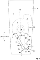
- the embodiment shown of a knee-joint bandage according to the invention comprises a tubular base body 1 made of an elastic textile material, for example an elastic knitted fabric, in particular a compression knitted fabric, which has a compression-giving, elastic weft thread.
- the base body 1 has an outer side a and, when the bandage is applied to a knee joint G, the inner side i facing the knee joint G, as in FIG Figure 3 shown.
- the knee joint bandage further comprises a first pad 2 arranged on the base body 1 and in particular integrated in the base body 1 and a tension band 3 connected to the first pad 2.
- the first pad 2 is made of an elastic material, for example silicone or silicone rubber or a rubber material is at least substantially U-shaped or horseshoe-shaped.
- the tension band connected to the first pad 2 in a tensile manner is made of an inelastic material or of a material that is at least less elastic than the material of the first pad 2 and has a first end 3a and a second end 3b.
- the drawstring 3 is composed of a total of three sections 3 ', 3 "and 3'", with a first section 3 'and a second section 3 "each on the outside a of the base body 1 and a third section connecting the first and second sections Section 3 '"is arranged in the interior of the tubular base body 1, that is to say on its inside i.
- the base body 1 Two openings 11, in particular in the form of slots, through which the tension band 3 is guided, are provided in the base body 1 for introducing and removing the tension band 3 into and out of the interior of the tubular base body 1.
- the third section 3 ′′ ′′ of the tension band 3 running inside the tubular base body 1 runs within the first pad 2.
- the third section 3 ′′ ′′ of the tension cord 3 is expediently cast into the elastic material of the first pad 2 and is thus tensile with the first pad 2 connected.
- the inner, third section 3 '''of the The tension band 3 can, however, also be arranged outside the first pad 2 and be connected to it in a tensile manner, for example by gluing.
- FIG. 1 an in the inside i of the base body 1 is Figures 1 and 2 Pocket 10 shown in dashed lines is provided.
- the pocket 10 can, for example, be sewn on the inside i of the base body 1 and connected to the base body 1 in this way.
- the pocket 10 is connected to the openings 11 in the base body 1, so that the third section 3 '''of the drawstring 3 can be inserted into the pocket 10 through one of the two openings 11 on one side. and can be guided out of the pocket 10 on the other side through the other opening 11.
- the pocket 10 and the first pad 2 arranged therein can be seen to have a bulge 2a in the medial-proximal area.
- This bulge 2a serves to exert a stimulating effect on the muscles
- the arranged in the pocket 10 first pad 2 encompasses the in Figure 1 Dashed patella K in the proximal as well as in the medial and lateral area.
- the directions related to the knee joint G medial m, lateral 1, proximal p and distal d are indicated by arrows.
- the two outer sections 3 'and 3 "of the tension band 3 are fixed by means of fixing means 4.
- the embodiment shown is both the first section 3 ', which contains the first end 3a of the tension band 3, and the second section 3 ′′, which contains the second end 3b of the tension band 3, each deflected by an associated deflection means 4a, 4b by 180 °.
- both the first end 3a and the second end 3b of the tension band 3 are each arranged on fastening means 4c, 4d with which the 180 ° deflected section of the tension band 3 is fixed to the respective outer section 3 'or 3 ".
- the deflection means 4a, 4b can be, for example, deflection eyes or - as in the exemplary embodiments of FIG Figures 1 and 2 shown - act around deflection openings in a tab 16 fastened on the outside a of the base body 1.
- the position of the deflection means 4a, 4b defines an anchoring point for each of the two sections 3 'and 3 "of the tension band 3, at which the respective section 3' or 3" of the Tension band 3 is anchored in relation to the base body 1.
- the first deflection means 4a assigned to the first section 3 'of the tension band 3 defines a first anchoring point 5a
- the second deflection means 4b assigned to the second section 3 "defines a second anchoring point 5b Figure 1
- both the first anchoring point 5a and the second anchoring point 5b lie both distal and medial to the sagittal plane M, which passes through the center of the patella K and contains the central longitudinal axis of the patellar tendon P.
- the two anchoring points 5a, 5b are both medial and distal to the patellar tendon P.
- the position of the anchoring points together with the position of the openings 11 through which the outer sections 3 ', 3 "of the tension band 3 are guided to the outside, determines the position of the outer sections 3' and 3" in relation to the base body 1, the outer sections 3 'and 3 "each extending between the associated opening 11 and the first anchoring point 5a and the second anchoring point 5b, respectively.
- the directions of the tensile forces exerted by the two outer sections 3 'and 3 "of the tension band 3 on the first pad 2 result from the position of the two outer sections 3' and 3" of the tension band 3, which correspond to the embodiment of FIG Figure 1 can be found.
- the two outer sections 3 'and 3 "of the tension band 3 enclose an angle of approximately 45 ° with one another.
- the two anchoring points 5a, 5b, at which the tension band 3 is anchored on the outside a of the base body 1, are moved downward in the distal direction, as a result of which the two outer sections 3 ' and 3 ′′ of the tension band 3 exert a tensile force directed in the respective longitudinal direction of the first and the second section 3 ′, 3 ′′ on the first pad 2.
- a force in the distal direction is exerted on the first pad 2 by the second section 3 ′′ of the tension band 3 running in the distal-proximal direction. Due to the asymmetrical arrangement of the two anchoring points 5a, 5b in relation to the sagittal plane M or in relation to the Patellar tendon P and the associated inclination of the first section 3 'of the tension band 3 (as from Figure 1 (can be seen), a tensile force exerted by the first section 3 'of the tension band 3, which comprises a force component in the distal direction and a force component in the medial direction, also acts on the first pad 2.
- the tension band 3 acts on the first pad 2 with a force pointing in the distal and medial direction, whereby the patella K is centered in its physiologically correct position when the knee joint is moved, in particular when the knee is bent
- Tensile force transmitted by the tension band 3 to the first pad 2 acts in the distal and medial direction on the patella K, which is surrounded by the first pad 2 in its proximal and medial-lateral area.
- the tensile force exerted by the tension band 3 on the first pad 2 results in lateralization of the patella K on the one hand and suppresses the patella K from being pushed up in the proximal direction on the other hand.
- FIG. 3 This mechanism is shown in the sectional view of Figure 3 can be seen in which the use of the knee joint bandage in a first therapy phase is shown by a sectional view of the knee joint bandage in a state applied to a flexed knee joint.
- the knee joint bandage is applied to the knee joint G in such a way that the first pad 2 with the third section 3 '''of the tension band 3 running therein surrounds the patella K in its proximal, lateral and medial area.
- the knee-joint bandage comprises, in addition to the first pad 2, which is arranged on the inside i of the base body 1 in the pocket 10, a second pad 6, which is also attached to the inside i of the base body 1 and is arranged distal to the patella K. .
- the position of the second pad 6 in the area below the first pad 2 is shown in dashed lines.
- the second pad 6 is designed in the form of a band and, when the knee joint bandage is placed on the knee joint G, runs across the patellar tendon P, as shown in FIG Figure 3 evident.
- the fastening elements 8, 9 can for example be the elements of a Velcro fastener, in particular a hook part and an associated fleece part of a Velcro fastener.
- a fastening element 8 in the form of a hook part of a Velcro fastener is arranged, which cooperates with a corresponding fleece part on the inside i of the base body 1, around the band-shaped second pad 6 detachable on the inside i of the base body 1 to be attached.
- the second pad 6 on the off Figure 3 apparent position on the inside i of the base body 1, the second pad 6 exerts a pressure on the patellar tendon P and thus puts it under tension when the knee joint moves. This relieves the strain on the tendons, bone attachments and cartilage structures in the knee joint.
- the second pad 6 has a stabilizing and relieving effect on the knee joint and counteracts movement restrictions in the event of degeneration of the knee joint.
- the patella K is pushed up in the proximal direction, which can be caused by the pressure exerted by the second pad 6 on the patellar tendon P, through which the patella K is located proximally and this prevents the first pad 2 surrounding it in the proximal and in the medial-lateral area.
- the patella K is centered in its physiologically correct position when the knee joint bandage is on, without the patella K being pushed up in the proximal direction (upward) or drifting in the lateral direction (outward).
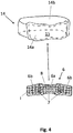
- the second pad 6, shown in detail below is at least essentially in the form of a band and has a longitudinal side which extends across the patellar tendon P when the knee joint bandage is put on, when the second pad 6, as in FIG Figure 3 shown, is attached to the inside i of the base body 1.
- the second pad 6 expediently has a middle section 6a and two laterally adjoining edge-side sections 6b, the edge-side sections 6b being bent downwards from the middle section 6a, ie, in the distal direction, as shown in FIG Figure 4 shown below.
- cranked is understood to mean that the edge-side sections 6b are at an angle extend at an angle in the range from 10 ° to 30 ° to the central section 6a.
- the distally cranked edge-side sections 6b enable a better fit and conformability over the Hoffa's fat body.
- the inside of the second pad 6 facing the knee joint when the knee bandage is applied has a plurality of stimulation elements 7, in particular in the form of elevations or projections and preferably in the form of knobs.
- the second pad 6 shown below can also be used in a separate second therapy phase without the base body 1 with the first pad 2 integrated therein.
- An in Figure 4 The retaining strap 14 shown above is provided, which has a receiving section 14a to which the second pad 6 can be detachably attached.
- the receiving section 14a expediently has detachable fastening means 15, in particular part of a Velcro fastener, with which the second pad 6 can be fastened to the receiving section 14a of the retaining strap 14.
- the fastening means 15 on the receiving section 14a of the retaining strap 14 are expediently designed as a corresponding fleece part of a Velcro fastener.
- the retaining strap 14 has a retaining portion 14b connected to the receiving portion 14a, the retaining portion 14b preferably being designed as a length-adjustable strap or as an elastic band, for example as a rubber band.
- the holding strap 14 with the second pad 6 attached to the receiving section 14a can be placed on the knee joint G, as in FIG Figure 5 shown.
- the retaining strap 14 runs in the area below the hollow of the knee and extends over the circumference of the upper section of the lower leg, the second pad 6 attached to the inside of the receiving section 14a of the retaining strap 14 lying in the area of the patellar tendon P and extending across the patellar tendon P. extends.
- the second pad 6 exerts pressure on the patellar tendon P, in particular when the knee joint G moves.
- the patellar tendon P and the tissue surrounding it are stimulated by the stimulation elements 7, as a result of which the blood flow to the body tissue is improved.
- the knee joint support according to the invention can thus on the one hand in the in Figure 3 and on the other hand in the manner shown in Figure 5 can be used for the therapy of knee joint complaints in the manner shown, whereby in the in Figure 3 first use form shown both the first pad 2 and the second pad 6 exerts a pressure on certain areas of the knee joint G and in the in Figure 5 The second form of use shown, a pressure is exerted on the patellar tendon P only by the second pad 6.
- the knee joint bandage according to the invention can therefore be used to treat various knee problems, such as damage to the knee joint in the sliding bearing between the patella and thigh, a high patella, femoropatellar pain syndrome, patella dislocations or subluxations, Osgood Schlatter's disease, gonar arthrosis or Joint effusions and irritation in the knee joint can be used for therapy on the one hand and also preventively on the other.
- a combined therapy with a use of the knee joint support according to the invention in the in Figure 3 The form of use shown in a first therapy phase and then in a second therapy phase in the in Figure 5 the form of use shown should be expedient.
- the bandage can, for example, be used with a second pad 6 attached to the inside for a therapy duration of 10 to 100 days in order to alleviate the symptoms of knee joint defects and to eliminate the cause.
- This first therapy phase can be followed by the second therapy phase, in which the second pad 6, together with the associated retaining strap 14, is used as a patellar tendon bandage Figure 3 is clearly placed on the knee joint.
- the second therapy phase can also be a preventive phase in which the patellar tendon bandage is used, for example, for prevention only while the patient is exercising.
- the deflection of the two outer sections 3 ', 3 "of the tension strap 3 can be dispensed with.
- the deflection means 4a, 4b used to deflect the sections 3', 3" of the tension strap 3 can also be fastened directly to the outside a of the base body 1 without deflection by means of the fastening means 4c, 4c arranged at the ends 3a, 3b.
- the anchoring points 5a, 5b of the tension band 3 are determined by the position of the fastening means 4c, 4d, by means of which the ends 3a, 3b of the tension band 3 are attached to the base body 1.
- the point at which the sections 3 ′, 3 ′′ of the tension band 3 are anchored or fixed on the base body 1 is decisive for the definition of the two anchoring points 5a, 5b.
- both the first pad 2 and the second pad 6 can be shaped differently.
- further bulges or additional stimulation elements can be provided on the first pad 2, which in particular contribute to interplanetary stimulation of the knee joint G.
- one of the two anchoring points can lie distal to the patella K and also lie in the line of the extension of the patellar tendon P in its longitudinal direction on the tibia S.
Landscapes
- Health & Medical Sciences (AREA)
- Nursing (AREA)
- Orthopedic Medicine & Surgery (AREA)
- Engineering & Computer Science (AREA)
- Biomedical Technology (AREA)
- Heart & Thoracic Surgery (AREA)
- Vascular Medicine (AREA)
- Life Sciences & Earth Sciences (AREA)
- Animal Behavior & Ethology (AREA)
- General Health & Medical Sciences (AREA)
- Public Health (AREA)
- Veterinary Medicine (AREA)
- Orthopedics, Nursing, And Contraception (AREA)
Applications Claiming Priority (1)
| Application Number | Priority Date | Filing Date | Title |
|---|---|---|---|
| DE102020101744.8A DE102020101744A1 (de) | 2020-01-24 | 2020-01-24 | Kniegelenkbandage |
Publications (1)
| Publication Number | Publication Date |
|---|---|
| EP3854358A1 true EP3854358A1 (fr) | 2021-07-28 |
Family
ID=74130067
Family Applications (1)
| Application Number | Title | Priority Date | Filing Date |
|---|---|---|---|
| EP21150861.9A Withdrawn EP3854358A1 (fr) | 2020-01-24 | 2021-01-11 | Bandage d'articulation de genou |
Country Status (2)
| Country | Link |
|---|---|
| EP (1) | EP3854358A1 (fr) |
| DE (1) | DE102020101744A1 (fr) |
Families Citing this family (1)
| Publication number | Priority date | Publication date | Assignee | Title |
|---|---|---|---|---|
| DE102023200768A1 (de) * | 2023-01-31 | 2024-08-01 | Bauerfeind Ag | Pelotte mit zugeordnetem gekrümmten Zügelelement |
Citations (4)
| Publication number | Priority date | Publication date | Assignee | Title |
|---|---|---|---|---|
| EP0492328A1 (fr) * | 1990-12-28 | 1992-07-01 | FERD. HAUBER GmbH & CO. KG | Genouillère |
| DE29803103U1 (de) * | 1998-02-21 | 1998-05-07 | Ferd. Hauber GmbH & Co KG, 72622 Nürtingen | Kniebandage |
| DE102013022088A1 (de) * | 2013-12-23 | 2015-06-25 | Bauerfeind Ag | Patellarsehnenbandage |
| EP2954879A1 (fr) | 2014-05-22 | 2015-12-16 | medi GmbH & Co. KG | Bandage de genou |
Family Cites Families (2)
| Publication number | Priority date | Publication date | Assignee | Title |
|---|---|---|---|---|
| DE29519978U1 (de) | 1995-12-16 | 1996-03-14 | Ferd. Hauber GmbH & Co KG, 72622 Nürtingen | Kniebandage |
| DE102008029825A1 (de) | 2008-06-25 | 2009-12-31 | Medi Gmbh & Co. Kg | Kniebandage |
-
2020
- 2020-01-24 DE DE102020101744.8A patent/DE102020101744A1/de not_active Withdrawn
-
2021
- 2021-01-11 EP EP21150861.9A patent/EP3854358A1/fr not_active Withdrawn
Patent Citations (5)
| Publication number | Priority date | Publication date | Assignee | Title |
|---|---|---|---|---|
| EP0492328A1 (fr) * | 1990-12-28 | 1992-07-01 | FERD. HAUBER GmbH & CO. KG | Genouillère |
| DE29803103U1 (de) * | 1998-02-21 | 1998-05-07 | Ferd. Hauber GmbH & Co KG, 72622 Nürtingen | Kniebandage |
| DE102013022088A1 (de) * | 2013-12-23 | 2015-06-25 | Bauerfeind Ag | Patellarsehnenbandage |
| EP3086746B1 (fr) | 2013-12-23 | 2018-09-12 | Bauerfeind AG | Bande de maintien rotulien |
| EP2954879A1 (fr) | 2014-05-22 | 2015-12-16 | medi GmbH & Co. KG | Bandage de genou |
Also Published As
| Publication number | Publication date |
|---|---|
| DE102020101744A1 (de) | 2021-07-29 |
Similar Documents
| Publication | Publication Date | Title |
|---|---|---|
| EP0627205B1 (fr) | Support pour la cheville | |
| EP0991381B1 (fr) | Dispositif pour stabiliser une articulation | |
| EP1906890B1 (fr) | Bandage pour l'articulation de la cheville | |
| DE102009038517B4 (de) | Baukastensystem zur Zusammenstellung einer Orthese für ein Knie und Verfahren zum Umbau einer Orthese aus diesem Baukastensystem | |
| EP3086746B1 (fr) | Bande de maintien rotulien | |
| EP1179325A1 (fr) | Bandage pour la cheville | |
| EP2491895B1 (fr) | Orthèse de cheville | |
| EP1093779B1 (fr) | Bandage pour décharger un muscle déchiré | |
| EP3210581A1 (fr) | Bandage pour pied destiné à la thérapie par compression des lymphoedèmes | |
| DE3637879A1 (de) | Kniegelenkbandage | |
| DE2724586A1 (de) | Orthopaedische schiene zur stuetzung des kniegelenkes | |
| DE3873741T2 (de) | Stuetzeinrichtung fuer kniescheibe. | |
| EP3854358A1 (fr) | Bandage d'articulation de genou | |
| DE102017117786B4 (de) | Schuh zum Dämpfen einer Fußbewegung über das Sprunggelenk | |
| DE202020100382U1 (de) | Kniegelenkbandage | |
| DE202024102521U1 (de) | Hüftorthese zur Mobilisierung eines Hüftgelenks | |
| EP3854357B1 (fr) | Bandage pour articulation de genou | |
| EP4312903B1 (fr) | Orthèse de pied à articulation rotoïde pour corriger les malpositions du pied | |
| EP4366669A1 (fr) | Bandage pour articulation du poignet ou de la cheville | |
| DE202020100383U1 (de) | Kniegelenkbandage | |
| EP1803425B1 (fr) | Remède orthopédique | |
| WO2023186955A1 (fr) | Orthèse pour allonger un membre inférieur | |
| EP4574103B1 (fr) | Orthèse de cheville | |
| DE9112765U1 (de) | Stützvorrichtung | |
| DE102023133446A1 (de) | Hüftorthese zur Mobilisierung eines Hüftgelenks |
Legal Events
| Date | Code | Title | Description |
|---|---|---|---|
| PUAI | Public reference made under article 153(3) epc to a published international application that has entered the european phase |
Free format text: ORIGINAL CODE: 0009012 |
|
| STAA | Information on the status of an ep patent application or granted ep patent |
Free format text: STATUS: THE APPLICATION HAS BEEN PUBLISHED |
|
| AK | Designated contracting states |
Kind code of ref document: A1 Designated state(s): AL AT BE BG CH CY CZ DE DK EE ES FI FR GB GR HR HU IE IS IT LI LT LU LV MC MK MT NL NO PL PT RO RS SE SI SK SM TR |
|
| STAA | Information on the status of an ep patent application or granted ep patent |
Free format text: STATUS: THE APPLICATION IS DEEMED TO BE WITHDRAWN |
|
| 18D | Application deemed to be withdrawn |
Effective date: 20220129 |