EP3854367B1 - Système de levage - Google Patents
Système de levage Download PDFInfo
- Publication number
- EP3854367B1 EP3854367B1 EP21152233.9A EP21152233A EP3854367B1 EP 3854367 B1 EP3854367 B1 EP 3854367B1 EP 21152233 A EP21152233 A EP 21152233A EP 3854367 B1 EP3854367 B1 EP 3854367B1
- Authority
- EP
- European Patent Office
- Prior art keywords
- clip
- pin
- bracket
- lifting system
- head formation
- Prior art date
- Legal status (The legal status is an assumption and is not a legal conclusion. Google has not performed a legal analysis and makes no representation as to the accuracy of the status listed.)
- Active
Links
Images



Classifications
-
- A—HUMAN NECESSITIES
- A61—MEDICAL OR VETERINARY SCIENCE; HYGIENE
- A61G—TRANSPORT, PERSONAL CONVEYANCES, OR ACCOMMODATION SPECIALLY ADAPTED FOR PATIENTS OR DISABLED PERSONS; OPERATING TABLES OR CHAIRS; CHAIRS FOR DENTISTRY; FUNERAL DEVICES
- A61G7/00—Beds specially adapted for nursing; Devices for lifting patients or disabled persons
- A61G7/10—Devices for lifting patients or disabled persons, e.g. special adaptations of hoists thereto
- A61G7/1073—Parts, details or accessories
-
- B—PERFORMING OPERATIONS; TRANSPORTING
- B66—HOISTING; LIFTING; HAULING
- B66C—CRANES; LOAD-ENGAGING ELEMENTS OR DEVICES FOR CRANES, CAPSTANS, WINCHES, OR TACKLES
- B66C1/00—Load-engaging elements or devices attached to lifting or lowering gear of cranes or adapted for connection therewith for transmitting lifting forces to articles or groups of articles
- B66C1/10—Load-engaging elements or devices attached to lifting or lowering gear of cranes or adapted for connection therewith for transmitting lifting forces to articles or groups of articles by mechanical means
- B66C1/62—Load-engaging elements or devices attached to lifting or lowering gear of cranes or adapted for connection therewith for transmitting lifting forces to articles or groups of articles by mechanical means comprising article-engaging members of a shape complementary to that of the articles to be handled
- B66C1/66—Load-engaging elements or devices attached to lifting or lowering gear of cranes or adapted for connection therewith for transmitting lifting forces to articles or groups of articles by mechanical means comprising article-engaging members of a shape complementary to that of the articles to be handled for engaging holes, recesses, or abutments on articles specially provided for facilitating handling thereof
-
- A—HUMAN NECESSITIES
- A61—MEDICAL OR VETERINARY SCIENCE; HYGIENE
- A61G—TRANSPORT, PERSONAL CONVEYANCES, OR ACCOMMODATION SPECIALLY ADAPTED FOR PATIENTS OR DISABLED PERSONS; OPERATING TABLES OR CHAIRS; CHAIRS FOR DENTISTRY; FUNERAL DEVICES
- A61G7/00—Beds specially adapted for nursing; Devices for lifting patients or disabled persons
- A61G7/10—Devices for lifting patients or disabled persons, e.g. special adaptations of hoists thereto
- A61G7/1049—Attachment, suspending or supporting means for patients
- A61G7/1059—Seats
-
- A—HUMAN NECESSITIES
- A61—MEDICAL OR VETERINARY SCIENCE; HYGIENE
- A61G—TRANSPORT, PERSONAL CONVEYANCES, OR ACCOMMODATION SPECIALLY ADAPTED FOR PATIENTS OR DISABLED PERSONS; OPERATING TABLES OR CHAIRS; CHAIRS FOR DENTISTRY; FUNERAL DEVICES
- A61G3/00—Ambulance aspects of vehicles; Vehicles with special provisions for transporting patients or disabled persons, or their personal conveyances, e.g. for facilitating access of, or for loading, wheelchairs
- A61G3/02—Loading or unloading personal conveyances; Facilitating access of patients or disabled persons to, or exit from, vehicles
- A61G3/06—Transfer using ramps, lifts or the like
- A61G3/062—Transfer using ramps, lifts or the like using lifts connected to the vehicle
-
- A—HUMAN NECESSITIES
- A61—MEDICAL OR VETERINARY SCIENCE; HYGIENE
- A61G—TRANSPORT, PERSONAL CONVEYANCES, OR ACCOMMODATION SPECIALLY ADAPTED FOR PATIENTS OR DISABLED PERSONS; OPERATING TABLES OR CHAIRS; CHAIRS FOR DENTISTRY; FUNERAL DEVICES
- A61G3/00—Ambulance aspects of vehicles; Vehicles with special provisions for transporting patients or disabled persons, or their personal conveyances, e.g. for facilitating access of, or for loading, wheelchairs
- A61G3/02—Loading or unloading personal conveyances; Facilitating access of patients or disabled persons to, or exit from, vehicles
- A61G3/06—Transfer using ramps, lifts or the like
- A61G3/063—Transfer using ramps, lifts or the like using lifts separate from the vehicle, e.g. fixed on the pavement
-
- A—HUMAN NECESSITIES
- A61—MEDICAL OR VETERINARY SCIENCE; HYGIENE
- A61G—TRANSPORT, PERSONAL CONVEYANCES, OR ACCOMMODATION SPECIALLY ADAPTED FOR PATIENTS OR DISABLED PERSONS; OPERATING TABLES OR CHAIRS; CHAIRS FOR DENTISTRY; FUNERAL DEVICES
- A61G5/00—Chairs or personal conveyances specially adapted for patients or disabled persons, e.g. wheelchairs
- A61G5/10—Parts, details or accessories
-
- A—HUMAN NECESSITIES
- A61—MEDICAL OR VETERINARY SCIENCE; HYGIENE
- A61G—TRANSPORT, PERSONAL CONVEYANCES, OR ACCOMMODATION SPECIALLY ADAPTED FOR PATIENTS OR DISABLED PERSONS; OPERATING TABLES OR CHAIRS; CHAIRS FOR DENTISTRY; FUNERAL DEVICES
- A61G7/00—Beds specially adapted for nursing; Devices for lifting patients or disabled persons
- A61G7/10—Devices for lifting patients or disabled persons, e.g. special adaptations of hoists thereto
- A61G7/1013—Lifting of patients by
- A61G7/1015—Cables, chains or cords
-
- A—HUMAN NECESSITIES
- A61—MEDICAL OR VETERINARY SCIENCE; HYGIENE
- A61G—TRANSPORT, PERSONAL CONVEYANCES, OR ACCOMMODATION SPECIALLY ADAPTED FOR PATIENTS OR DISABLED PERSONS; OPERATING TABLES OR CHAIRS; CHAIRS FOR DENTISTRY; FUNERAL DEVICES
- A61G7/00—Beds specially adapted for nursing; Devices for lifting patients or disabled persons
- A61G7/10—Devices for lifting patients or disabled persons, e.g. special adaptations of hoists thereto
- A61G7/1073—Parts, details or accessories
- A61G7/1078—Clamps for flexible harnesses
Definitions
- the present invention relates to a lifting system for a vehicle, particularly for a lifting system for a mobility device.
- the lifting system comprises a bracket 1 for a lifting a mobility scooter or the like.
- the scooter may be lifted into a user's vehicle.
- the bracket 1 is removably connected to the scooter via a post 38 fixed to the scooter.
- the bracket 1 comprises a pair of lateral spreader bars 3 at the sides thereof.
- the spreader bars 3 comprise a fastener 37 extending therethrough configured to connect to a hoist mechanism to allow lifting of the mobility scooter.
- the hoist mechanism comprises a clip 3' configured to engage and retain the fastener.
- the clip 3' comprises a spring clip to retain the fastener in place.
- EP1928390B1 A further prior art system is shown in EP1928390B1 .
- the spring clip In order to adequately secure the fastener in place, the spring clip must have sufficient biasing force. This biasing force must be overcome when disconnecting the fastener, which may be difficult for those with reduce mobility, strength and/or dexterity (i.e. the most likely users of a mobility scooter).
- the scooter is configured to be placed into the boot of a car, and so space is at a premium.
- the carabiner clip or loop project outwardly and so may engage the side walls of the car.
- carabiners and other clips may rattle when the user is driving the vehicle with the scooter stowed therein, which may cause irritation or may cause the carabiner/clip to become disconnected.
- a lifting system for a mobility device comprising: a bracket fixed to the mobility device; a hoist connector configured to removably connect to the bracket to provide lifting of the mobility device in use; where one of the bracket and the hoist connector comprises a pin and the other of the bracket and the hoist connector comprises a clip, the pin comprising a head formation and a neck formation, wherein the clip comprises an aperture configured to pass over the head formation in use and into engagement with the neck formation such that the clip is held on the pin.
- the clip may have a close fit with the head formation to prevent unintentional disengagement from the pin in use
- a shape of an outer surface of the head formation may be configured to conform to the shape of an inner surface of the clip aperture.
- the neck formation may comprise a spacer arranged to abut the bracket to hold the head formation at a predetermined spacing from the bracket in use.
- the neck formation may comprise a shaft portion configured to extend through the bracket.
- the neck formation may comprise the shaft portion and the spacer, the width or profile of the spacer being different from the width and/or profile of the shaft portion.
- the biasing member may be interposed between the head formation and bracket.
- the biasing member may be arranged to contact the clip when in engagement with the pin.
- the biasing member may surround the neck formation of the pin.
- the biasing member may comprise one or more side wall configured to engage the head formation and/or the bracket.
- the biasing member may have two spaced side walls and the clip is held between the side walls of the biasing member when in engagement with the pin.
- the biasing member may be configured to resiliently retain the clip on the pin.
- the pin may comprise a magnet, the magnet comprising a substantially annular shape.
- the head formation may comprise a locating feature configured to engage a corresponding locating feature on the clip to ensure correct orientation of the clip relative to the head formation when the clip is passed thereover the pin.
- the locating feature may comprise a protrusion on one of the aperture and the head formation configured to engage a recess on the other of the aperture and the head formation.
- the head formation and/or aperture may be substantially circular.
- the clip and/or pin may comprise an angled/chamfered surface configured to guide the clip and pin into alignment when passing thereover.
- the angled surface may comprise a tapered surface on a side of the head formation distal the bracket in use.
- the angled/chamfered surface may be provided on one side of the head formation or clip only and/or an opposing side of the head formation or clip may comprise a flat face.
- the bracket may comprise an elongate aperture therein and the pin may be connected to the bracket through the aperture at a desired location along the length of the aperture.
- a portion of the pin may comprise at least one flat surface configured to engage the elongate aperture to prevent rotation of the pin therein.
- the bracket may be connected to the mobility device via an upstanding post of the mobility device, the bracket being rigidly mounted with the post.
- a plurality of said brackets may be provided and the post is provided with a cross bar arranged to space the brackets on either side of the post.
- the lifting system may comprise a hoist arranged to raise and lower the hoist connector in use.
- a lifting system for a mobility device comprising:
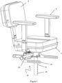
- Figures 1 and 2 show a seating assembly 2.
- the seating assembly 2 is configured to support a user of a vehicle in use (i.e. provide a seat).
- the seating assembly 2 is intended for use with a vehicle adapted for people with mobility issues, such as a mobility scooter, power chair, or other electrically powered mobility device to be lifted using a hoist.
- the vehicle can thus be lifted into and out of, e.g. the boot/trunk of, an automobile or other passenger vehicle using the hoist.
- the seating assembly 2 comprises a seat portion 4 configured to support the user's buttocks and legs in use.
- a back-rest 6 is provided at a rear side of the seat portion and is configured to supports the user's back in use, e.g. in a lumbar and/or thoracic region of the spine.
- Two arm-rests 8 are provided at the sides of the seat portion and are configured to supports the user's arms, e.g. forearms, in use.
- the seat portion 4 and/or back-rest 6 and/or arm-rests 8 may comprise cushioning material or the like configured to support and provide comfort for the user. Conventional foam or other padding may be used.
- the assembly 2 comprises a mounting arrangement configured to connect the assembly 2 to the vehicle, e.g. a mobility scooter.
- the mounting arrangement comprises a yoke 12 configured to support the seat portion 4, the back-rest 6 and the arm-rests 8 in use, whilst allowing simple disassembly thereof by an end user.
- the back-rest 6 and arm-rests 8 are removably attached to the yoke 12 (i.e. via arms 14).
- the back-rest 6 and arm-rests 8 are therefore separable from the seat portion 4.
- the back-rest 6 and arm-rests 8 are configured to be received within the arms 14 (i.e. within a hollow section of the arms 14).
- the yoke 12 is itself mounted to a support structure 10 on the vehicle. Although a specific seat assembly is described above, the precise seat makeup is not critical and other seats could be mounted to the
- the support structure 10 of the mounting arrangement comprises a base portion 16 configured to be connected to the vehicle in use.
- the base portion 16 is configured to be connected to the vehicle in a permanent or semi-permanent fashion (i.e. the connection is maintained in day-to-day use).
- the base portion 16 is typically a permanent installation of the vehicle.
- the base portion 16 comprises a pillar/post 18 mounted so as to extend upwardly from the vehicle.
- the pillar 18 comprises a plurality/series of apertures 20 along a lower portion thereof to receive fasteners or the like.
- An upper end of the pillar 18 comprises a mounting plate 22 for mounting of both an upper pillar portion 24 and a lifting support structure 26 configured to allow lifting of the vehicle, e.g. using a hoist mechanism.
- the lifting structure 26 is thus rigidly mounted to the pillar 18.
- the upper pillar portion 24 may be affixed atop the pillar 18 using other conventional means and provides a formation arranged to receive the yoke 12 of the seat assembly.
- the upper pillar portion 24 may be hollow or recessed in this regard, i.e. arranged to receive a protrusion of the yoke 12, or vice versa.
- the yoke 12 is removably coupled to the base portion 16 when mounted.
- the yoke 12, seat portion 4, back-rest 6 and arm-rests 8 are therefore separable from the pillar 18 of the vehicle.
- the lifting structure 26 comprises a cross bar 28 and a bracket 30 depending from each end of the cross bar 28.
- the brackets 30 are provided at either side of the seat portion 4. The brackets thus provide spaced attachment points for attaching to a spreader bar on the hoist in use.
- the brackets 30 comprise a first portion 32 connected to the cross bar 28 and a second portion 34 extending therefrom.
- the second portion 34 is angled with respect to the first portion 32 and is elongate in form.
- the second portion 34 may extend in a substantially horizontal direction in use and provides the attachment point for the lifting system described below.
- the bracket 30 comprises a plurality of apertures 36 extending therethrough configured to allow attachment of the hoist mechanism.
- the apertures are spaced along the second portion 34, and thus are spaced in a horizontal direction in use.
- a single elongate aperture 36 may be provided.
- the hoist mechanism is connected to the bracket 30 via a lifting system 38, which may be described as being a clip and pin type arrangement, by which a clip is removably engageable with a pin on the bracket to lift the vehicle.
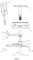
- a first embodiment of the lifting system 38 is shown in closer detail in figure 5 .
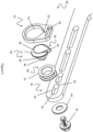
- the lifting system 38 comprises a pin 40.
- the pin 40 is configured to extend through the aperture 36 (e.g. via a neck or shaft portion 68 thereof).
- the pin 40 is movably received within the aperture 36.
- the pin 40 is secured within the aperture using a fastener, for example, a threaded bolt 42.
- the pin 40 itself thus acts as a retainer (e.g. a nut).
- the pin 40 may therefore be removable from the bracket 30.
- a washer 44 may be interposed between the head of the bolt 42 and the bracket 30.
- the pin 40 in the examples described herein has a head formation 56 of greater width dimension relative to a neck portion, e.g. shaft portion 68, extending behind the head formation.
- a portion of the pin 40 extending through the aperture 36 may be shaped to prevent rotation of the pin 40 relative to the bracket 30.
- the portion may comprises one or more flat edge 46 configured to engage an inner edge 48 of the aperture.
- the portion may be substantially square/rectangular or a rounded square/rectangle.
- the ends 50 of the aperture 36 may be shaped to conform with the shape of the portion.
- the bracket 30 is located approximately above the centre of the gravity of the scooter. Therefore, the pin 40 can be moved along the aperture 36 and/or to an adjacent aperture to allow fine adjustment of the location of the pin 40 to a position directly above the centre of the gravity of the scooter. This prevents unwanted tipping or swinging of the scooter and allows the hoist mechanism to be attached to scooter at a single point on each side of the scooter.
- the lifting 38 system comprises a clip 52 configured to engage the pin 40.
- the clip 52 provides a detachable connection between the hoist mechanism and the bracket 30 in use (i.e. a hoist connector).
- the clip 52 comprises an aperture 54 configured to pass over the pin 40.
- the clip 52 passes over a head formation 56 of the pin 40 that comprises an increased width.
- the head formation is spaced from the bracket 20, e.g. by the neck 68, such that the clip is retained between the head formation 56 and the bracket 20.
- Once the clip has passed over the head portion 56 it can contact the neck portion of reduced width, thereby causing a natural offset of the aperture 54 and head formation 56 that prevents unwanted removal of the clip 52. That is to say the clip 52 will abut the rear of the head formation unless the user purposely aligns the aperture 54 with the head formation 56 to remove the clip.
- the head formation 56 is shaped to provide a close fit with the aperture 54 (i.e. the outer surface is of the head formation 56 is the same shape/size as the inner surface of the aperture 54).
- the aperture 54 therefore must be accurately aligned with the head formation 56 to allow removal of the clip 52 by passing the clip 52 back over the pin 40.
- the clip 52 is loosely held on the pin 40 (i.e. is not held by a latch, clip or the like). The close fit therefore ensures the clip 52 does not unintentionally disconnect from the pin 40, for example, by shaking of the clip 52.
- the pin 40/aperture 54 may be substantially circular.
- the clip 52 therefore provides a ring-like or annular arrangement.
- the pin 40 comprises a locating feature 58 to ensure correct alignment/orientation of the clip 52 relative to the pin 40 when passing thereover.
- the locating feature 58 comprises a protrusion 60 located on the head formation 56 configured to be received a correspondingly shaped recess 62 in the clip aperture 54. This ensures the clip 52 can only pass over the pin 40 in a single orientation. Any relative rotation between the clip 52 and pin 40, once connected, will prevent removal of the clip 52 from the pin 40 due to the offset of the protrusion 60 and recess 62.
- the protrusion 60 extends beyond the edge of the head formation 56.
- the protrusion 60/recess 62 may be substantially triangular/wedge shaped.
- the recess 62 is provided adjacent a portion of the clip 52 configured to receive a webbing/belt of the hoist mechanism (e.g. via aperture 64).
- the recess 62 is therefore provided at an uppermost side of the aperture 54 during lifting.
- the webbing may become slack, thus the recess 62 will naturally rotate away from the protrusion 60. This prevents disconnection of the hoist mechanism from the mobility vehicle during transit, and so the user does not have to reconnect the system in the limited space provide in the transport vehicle (e.g. within the car boot).
- the protrusion 60/recess 62 may not be located at top dead centre of the aperture, e.g. potentially being located at the side or the lowermost portion of the pin 40/clip 52 (i.e. at opposing side of the clip 52 from the connection between he webbing and the clip).
- a plurality of recesses 62 may be provided to allow disconnection at two or more select orientations.
- the locating feature 58 can be provided by an irregular and/or asymmetrically shaped pin 40/aperture 54.
- a resilient member 66 is provided between the pin 40 and the clip 52.
- the resilient member comprises a resiliently deformable material, for example, rubber or silicone.
- the resilient member therefore prevents rattling of the clip 52 against the pin 40 and/or the bracket 20.
- the resilient member 66 surrounds a shaft portion 68 of the pin 40 and sits thereon (e.g. in an annular fashion). The resilient member is therefore interposed between the head formation 56 and the bracket 20, i.e. behind the head formation.
- the resilient member 66 comprises a plurality of upstanding side walls 70 configured to engage the bracket 20 and the pin head formation 56 respectively.
- the side wall have a width less than or equal to the width of the clip aperture 54 to allow the clip 52 to pass thereover.
- the clip 52 is configured to surround the resilient member 66. For example, when lifting, the inner surface of the aperture 54 engages the lowermost side of the resilient member 66.
- the resilient member may comprise a collar or cuff formation.
- the resilient member provide a biasing force, i.e. may be in compression, to press the clip 52 against the head formation 56 or bracket 20 when the clip is attached over the pin.
- the clip may be a loose fit over the resilient member and the resilient member may constrain the freedom of movement available to the clip when on the pin in use.
- the head formation 56 may have tapered/bevelled edges 72 configured to guide the clip 52 into alignment with the pin 40.
- the tapered edges 72 are provided on a side of the head formation 56 distal the bracket 30, i.e. a front/outer face of the head formation.
- each bracket 30 comprises a pin 40/clip 52 arrangement.
- a plurality of pin 40/clip 52 arrangements may be provided on each bracket 30.
- a second embodiment of the lifting system 38 is shown in figure 5 .
- the second embodiment is similar to the first embodiment, and like features will not be repeated for the sake of brevity.
- a fastener 42 extends through the head formation 56 via an aperture 78 therein.
- the fastener is connected to a retainer (e.g. a nut 80) on the opposing side of the bracket 30.
- the pin 40 is therefore releasable from the side bracket 30 adjacent the head formation 56.
- the locating feature 58 is absent in the second embodiment.
- the head formation 56 and the clip aperture 54 are therefore circular.
- the head formation 56 retains the tapered surface, thus providing a frustoconical shape.
- Rattling of the clip 52 is prevented using one or more magnet.
- a magnet may be provided on one or more of the clip 52, pin 40 or bracket 20, which is attracted to a magnetic material or magnet on the clip 52, pin 40 or bracket 20 accordingly. Additionally, this may further prevent unintentional disconnection of the pin 40 and clip 52, i.e. by attracting the clip onto the magnet/shaft behind the head formation 56 such that the clip is offset from the alignment required to remove the clip from the pin.
- the magnet is embedded in/on the pin 40, thus retaining clip 52 against the pin 40.
- the magnet comprises an annular/ring shaped magnet 82.
- the magnet is attached to a side of the head formation 56 proximal the bracket 30 (i.e. interposed the pin 40 and bracket 30).
- the magnet 82 is used in addition to the resilient member 66 of the previous embodiment.
- the pin 40 and/or 52 comprise a steel and/or magnetic material.
- the clip 52 may comprise a mild (carbon) steel.
- the pin 40 may comprise a stainless steel.
- the magnet comprises a neodymium magnet.
- any suitable magnetic material may be used.
- the magnet 82 may act as a spacer between the bracket and head formation 56. Additionally/alternatively, the rear side of the head formation 56 may comprise a shaft or other spacer formation as described above in relation figure 4 .
- the hoist mechanism 84 is shown in figures 6 and 7 .
- the hoist mechanism is described in the applicant's co-pending application GB2003138.1 , which is incorporated by reference herein.
- the hoist mechanism 84 is configured to be fixed to the vehicle (e.g. a car or van) adjacent a door or other opening, for example, a boot/trunk door, to allow the user to lift the load in and out of the vehicle.
- vehicle e.g. a car or van
- a door or other opening for example, a boot/trunk door
- the hoist mechanism 84 comprises a boom generally indicated at 86.
- the boom 86 is configured to be rotationally attached to the vehicle.
- the boom 86 comprises a plurality of connectors 88 to allow a connection to a post or other fixture within in the car.
- the connectors 88 comprise apertures/loops to permit rotation relative to the post.
- the hoist 84 may therefore be stored inside the vehicle when not in use and then swung out of the vehicle when required.
- a rotatable connection may also be provided at a base of the boom 86.
- the boom is thus swivelable as a whole about an upright/vertical axis.
- the boom 4 comprises a metallic beam, for example, a steel box-section.
- Webbing referred to herein as a belt 90, depends from the boom structure 86 over the distal/free end thereof and is configured to be attached to the article to be lifted, e.g. the mobility scooter.
- An actuator 92 in the form of an electric motor, is mounted to the boom 86 structure.
- the actuator 92 is mounted to a central portion of the boom 86 along with a spool 94 for the belt 90.
- the belt 90 is operatively connected to an actuator 92 to retract/extend the belt 90.
- the belt 90 extends through/along a hollow interior the boom 86, thereby preventing the user interfering with the belt 90.
- the belt 90 is connected to the spool 94 and the belt 90 is configured to be wound to/from the spool 94 by the actuator 92.
- the hoist 84 therefore provides a winch like arrangement for selective payout/retraction of the belt 90.
- the belt 90 comprises a connection member 96 to orient the belt 90 for connection to the scooter.
- the connection member 96 comprises a cross-bar or spreader-bar 98, arranged to be substantially horizontal in use. End portions 100 are telescopically connected to the cross-bar 98, allowing variation of the width of the connection member 96.
- a further belt 102 extends from the end portions 100. The clips 52 are attached to the end of respective further belts 102.
- the hoist mechanism 84 is brought into alignment with the mobility scooter, such that the spreader bar 98 is over the seat post 18 and the clips 52 are proximal the brackets 30.
- the clips 52 can then be passed over the respective pins 40, thereby securing the hoist mechanism to the scooter via the lifting system.
- the scooter may then be raised or lowered using the hoist mechanism as required.
- the present invention avoids the use of spring clips or carabiners or the like, therefore allowing simple and convenient disconnection of the mobility scooter from the hoist mechanism. Due to the loose connection between the pin and the clip, disconnection can be performed using a single hand and can be perform by those with mobility/dexterity issues. However, the close fit prevents rattling of the clip, which can be noisy and/or cause to the clip to disconnect.
- the resilient member and/or magnet prevent rattling of the clip, thus preventing unintentional disconnection of the hoist mechanism and the scooter and/or irritation to the user.
- the lifting system provides a compact configuration thus allow use of the hoist mechanism in more compact environments. Additionally, this provides more space for the user's hand if disconnection of the hoist and the scooter is required.
Landscapes
- Health & Medical Sciences (AREA)
- Public Health (AREA)
- Life Sciences & Earth Sciences (AREA)
- Animal Behavior & Ethology (AREA)
- General Health & Medical Sciences (AREA)
- Veterinary Medicine (AREA)
- Nursing (AREA)
- Engineering & Computer Science (AREA)
- Mechanical Engineering (AREA)
- Load-Engaging Elements For Cranes (AREA)
- Seats For Vehicles (AREA)
Claims (12)
- Système de levage (38) pour un dispositif de mobilité comprenant :un support (30) configuré pour être fixé au dispositif de mobilité,un connecteur de palan configuré pour se connecter de manière amovible au support (30) afin de permettre le levage du dispositif de mobilité en cours d'utilisation ;l'un du support (30) et du connecteur de palan comprenant une broche (40) et l'autre du support (30) et du connecteur de palan comprenant une attache (52), la broche (40) comprenant une formation de tête (56) et une formation de col,dans lequel l'attache comprend une ouverture (54) configurée pour passer au-dessus de la formation de tête (56) en cours d'utilisation lorsque l'ouverture (54) et la formation de tête (56) sont alignées et pour passer en prise avec la formation de col de telle sorte que l'attache (52) soit maintenue de manière lâche sur la broche (40), l'ouverture (54) étant en ajustement étroit avec la formation de tête (56) pour empêcher un désengagement involontaire de la broche (40) en cours d'utilisation,dans lequel un élément de sollicitation est agencé pour éloigner l'attache (52) d'un état dans lequel l'ouverture (54) est alignée avec la formation de tête (56) lorsqu'elle est en prise avec la broche (40),caractérisé en ce que le l'élément de sollicitation comprend un aimant (82) prévu sur la broche (40) ou l'attache (52), et l'autre de la broche (40) ou de l'attache (52) comprenant un aimant ou un matériau magnétique de telle sorte que la broche (40) et l'attache (52) sont attirés mutuellement de manière à retenir l'attache (52) sur la broche (40).
- Système de levage (38) selon la revendication 1, dans lequel une forme d'une surface externe de la formation de tête (56) est configurée pour épouser la forme d'une surface interne de l'ouverture de l'attache (54).
- Système de levage (38) selon l'une quelconque des revendications précédentes, dans lequel la formation de col (68) comprend une entretoise agencée pour venir en butée contre le support (30) afin de maintenir la formation de tête (56) à un espacement prédéterminé du support (30) en cours d'utilisation.
- Système de levage (38) selon l'une quelconque des revendications précédentes, dans lequel la formation de col comprend une partie d'arbre (68) configurée pour s'étendre à travers le support.
- Système de levage (38) selon l'une quelconque des revendications précédentes, dans lequel l'élément de sollicitation est agencé pour solliciter l'attache en contact avec le col.
- Système de levage (38) selon l'une quelconque des revendications 1 ou 5, dans lequel l'élément de sollicitation est configuré pour retenir de manière élastique l'attache sur la broche.
- Système de levage (38) selon l'une quelconque des revendications 1 ou 5 à 6, dans lequel l'élément de sollicitation est formé d'un matériau élastique.
- Système de levage selon la revendication 1, dans lequel l'aimant ou le matériau magnétique est prévu sur un côté de la formation de tête proximal au support.
- Système de levage (38) selon l'une quelconque des revendications précédentes, dans lequel la formation de tête (56) comprend un élément de localisation (58) configuré pour venir en prise avec un élément de localisation correspondant (62) sur l'attache pour garantir une orientation correcte de l'attache par rapport à la formation de tête lorsque l'attache (52) est passé au-dessus de la broche (40).
- Système de levage (38) selon l'une quelconque des revendications précédentes, dans lequel l'attache (52) et/ou la broche (40) comprennent une surface inclinée/chanfreinée (72) configurée pour guider l'attache (52) et la broche (40) en alignement lorsqu'elles passent au-dessus de celle-ci.
- Système de levage (38) selon la revendication 10, dans lequel la surface inclinée/chanfreinée (72) est prévue sur un côté de la formation de tête (56) ou de l'attache (52) uniquement et/ou un côté opposé de la formation de tête (56) ou de l'attache (52) comprend une face plane.
- Système de levage (38) selon l'une quelconque des revendications précédentes, dans lequel le support (30) est raccordé au dispositif de mobilité via un montant vertical (18) du dispositif de mobilité, le support (30) étant assemblé rigidement au montant (18).
Applications Claiming Priority (1)
| Application Number | Priority Date | Filing Date | Title |
|---|---|---|---|
| GB2000907.2A GB2591251B (en) | 2020-01-22 | 2020-01-22 | Lifting system |
Publications (3)
| Publication Number | Publication Date |
|---|---|
| EP3854367A1 EP3854367A1 (fr) | 2021-07-28 |
| EP3854367B1 true EP3854367B1 (fr) | 2024-03-27 |
| EP3854367C0 EP3854367C0 (fr) | 2024-03-27 |
Family
ID=69636928
Family Applications (1)
| Application Number | Title | Priority Date | Filing Date |
|---|---|---|---|
| EP21152233.9A Active EP3854367B1 (fr) | 2020-01-22 | 2021-01-19 | Système de levage |
Country Status (4)
| Country | Link |
|---|---|
| US (1) | US11642268B2 (fr) |
| EP (1) | EP3854367B1 (fr) |
| AU (1) | AU2021200333B2 (fr) |
| GB (1) | GB2591251B (fr) |
Families Citing this family (3)
| Publication number | Priority date | Publication date | Assignee | Title |
|---|---|---|---|---|
| GB202201732D0 (en) * | 2022-02-10 | 2022-03-30 | Braunability Europe Ab | Hoist for a mobility device |
| GB2616329B (en) * | 2022-12-07 | 2024-07-24 | Autochair Ltd | Pin assembly for a lifting system |
| CN117752499A (zh) * | 2023-12-22 | 2024-03-26 | 季华实验室 | 患者转运装置 |
Family Cites Families (21)
| Publication number | Priority date | Publication date | Assignee | Title |
|---|---|---|---|---|
| US717663A (en) | 1902-02-20 | 1903-01-06 | Edwin Fabian | Car-coupling. |
| US1113781A (en) | 1913-12-20 | 1914-10-13 | Fredrick W Griffin | Pipe-vise holder. |
| US2975434A (en) | 1958-06-30 | 1961-03-21 | Frederick M Butler | Hospital patient lift attachment |
| SU472887A1 (ru) * | 1973-04-02 | 1975-06-05 | Горьковское Объединение По Производству Автомобилей ( Авто Газ) | Захватное устройство дл грузов с цапфой |
| FR2699129B1 (fr) * | 1992-12-15 | 1995-02-10 | Rene Baboulin | Dispositif pour le transfert, dans et hors d'un véhicule, d'au moins une partie formant le siège d'un fauteuil roulant destiné à un handicapé; fauteuil et véhicule intégrant en partie ce dispositif. |
| NL9401483A (nl) * | 1994-09-12 | 1996-04-01 | Thyssen De Reus Bv | Zweeflift en samenstel van een zweeflift en een rolstoel of dergelijk draag- of vervoermiddel. |
| GB2419152A (en) * | 2004-10-14 | 2006-04-19 | Sunrise Medical Ltd | Attachment device which attaches lifting sling to hoist |
| US20060216126A1 (en) * | 2005-03-22 | 2006-09-28 | Richard Mechling | Magnetic wheelchair seating belt storage system |
| NL1029988C2 (nl) * | 2005-09-20 | 2007-03-21 | Joyincare Group B V | Hijsinrichting voor personen en daarbij behorende gesp. |
| WO2008007222A2 (fr) * | 2006-07-07 | 2008-01-17 | Arjo Hospital Equipment Ab | Dispositif monte-charge doté d'une division de fixation de corde |
| US8398356B2 (en) * | 2011-05-16 | 2013-03-19 | Honda Motor Co., Ltd. | Automotive wheelchair mobility system |
| US9327947B2 (en) | 2012-11-26 | 2016-05-03 | Mickel Davis | All-terrain vehicle lifting crane apparatus |
| WO2016106455A1 (fr) * | 2014-12-30 | 2016-07-07 | Arjohuntleigh Magog Inc. | Attache de verrouillage pour élingue de patient |
| WO2016140673A1 (fr) * | 2015-03-05 | 2016-09-09 | The Crosby Group LLC | Ensemble boulon à œil tournant à mécanisme de verrouillage |
| GB2542556A (en) | 2015-09-16 | 2017-03-29 | Tomcat Special Needs Innovation Ltd | Seat docking apparatus |
| US20170137265A1 (en) * | 2015-11-13 | 2017-05-18 | Keith Menville | Portable Apparatus For Lifting Objects |
| GB2553135B (en) | 2016-08-25 | 2021-08-04 | Autochair Ltd | Lifting bracket |
| GB201619491D0 (en) | 2016-11-17 | 2017-01-04 | Autochair Ltd | A hoist mechanism and a stepless adjustment means |
| US10772777B2 (en) | 2017-06-02 | 2020-09-15 | Liko Research & Development Ab | Linkage assemblies for person lifting apparatuses |
| US11014791B2 (en) | 2018-04-05 | 2021-05-25 | Vermeer Manufacturing Company | Self-raising winch boom and control systems and methods associated therewith |
| EP3788903B1 (fr) * | 2019-09-09 | 2024-05-08 | MOPLAN, Studio za oblikovanje, d.o.o. | Fermeture à renforcement magnétique |
-
2020
- 2020-01-22 GB GB2000907.2A patent/GB2591251B/en active Active
-
2021
- 2021-01-19 AU AU2021200333A patent/AU2021200333B2/en active Active
- 2021-01-19 EP EP21152233.9A patent/EP3854367B1/fr active Active
- 2021-01-21 US US17/154,113 patent/US11642268B2/en active Active
Also Published As
| Publication number | Publication date |
|---|---|
| US20210220199A1 (en) | 2021-07-22 |
| US11642268B2 (en) | 2023-05-09 |
| EP3854367A1 (fr) | 2021-07-28 |
| GB2591251A (en) | 2021-07-28 |
| AU2021200333B2 (en) | 2025-11-27 |
| GB2591251B (en) | 2022-08-24 |
| GB202000907D0 (en) | 2020-03-04 |
| AU2021200333A1 (en) | 2021-08-05 |
| EP3854367C0 (fr) | 2024-03-27 |
Similar Documents
| Publication | Publication Date | Title |
|---|---|---|
| US11642268B2 (en) | Lifting system | |
| EP0901935B1 (fr) | Fixation pour sièges d'enfants | |
| US20160200225A1 (en) | Child safety seat | |
| RU2758156C2 (ru) | Детское кресло безопасности | |
| EP2720903B1 (fr) | Base pour siège de sécurité enfant | |
| US20220097577A1 (en) | Child safety seat assembly | |
| US20140334893A1 (en) | Two Point Wheelchair Securement System | |
| US7207469B2 (en) | Mounting system for audio visual equipment | |
| US20110219529A1 (en) | Commode Chair | |
| US20130313874A1 (en) | Child safety seat for vehicles | |
| US6575492B2 (en) | Lateral torso supports for folding wheelchairs | |
| US20110193392A1 (en) | Foot Rest and Method of Improving Motor Vehicle Occupant Comfort During Extended Travel | |
| EP2238959A1 (fr) | Système d'ancrage de fauteuil roulant | |
| US8684468B2 (en) | Back support for chair | |
| AU2024204064B2 (en) | Child safety seat and seat thereof | |
| WO2009099401A1 (fr) | Système de ceinture de sécurité pour automobile | |
| CN222004982U (zh) | 可以无极调节安装高度的汽车座椅头枕 | |
| EP4190629A1 (fr) | Siège comprenant des moyens d'espacement de sangles de harnais | |
| JP2013530083A (ja) | 自動車用シート | |
| CN213413729U (zh) | 车辆用座椅 | |
| US20030011223A1 (en) | Mobile tether apparatus | |
| CA2635462A1 (fr) | Ceinture de securite d'automobile | |
| TW202517484A (zh) | 車用動物繫繩組件 | |
| HK40035249A (en) | Child safety seat assembly | |
| CN120735835A (zh) | 载具 |
Legal Events
| Date | Code | Title | Description |
|---|---|---|---|
| PUAI | Public reference made under article 153(3) epc to a published international application that has entered the european phase |
Free format text: ORIGINAL CODE: 0009012 |
|
| STAA | Information on the status of an ep patent application or granted ep patent |
Free format text: STATUS: THE APPLICATION HAS BEEN PUBLISHED |
|
| AK | Designated contracting states |
Kind code of ref document: A1 Designated state(s): AL AT BE BG CH CY CZ DE DK EE ES FI FR GB GR HR HU IE IS IT LI LT LU LV MC MK MT NL NO PL PT RO RS SE SI SK SM TR |
|
| STAA | Information on the status of an ep patent application or granted ep patent |
Free format text: STATUS: REQUEST FOR EXAMINATION WAS MADE |
|
| 17P | Request for examination filed |
Effective date: 20220128 |
|
| RBV | Designated contracting states (corrected) |
Designated state(s): AL AT BE BG CH CY CZ DE DK EE ES FI FR GB GR HR HU IE IS IT LI LT LU LV MC MK MT NL NO PL PT RO RS SE SI SK SM TR |
|
| GRAP | Despatch of communication of intention to grant a patent |
Free format text: ORIGINAL CODE: EPIDOSNIGR1 |
|
| STAA | Information on the status of an ep patent application or granted ep patent |
Free format text: STATUS: GRANT OF PATENT IS INTENDED |
|
| INTG | Intention to grant announced |
Effective date: 20231012 |
|
| GRAS | Grant fee paid |
Free format text: ORIGINAL CODE: EPIDOSNIGR3 |
|
| GRAA | (expected) grant |
Free format text: ORIGINAL CODE: 0009210 |
|
| STAA | Information on the status of an ep patent application or granted ep patent |
Free format text: STATUS: THE PATENT HAS BEEN GRANTED |
|
| AK | Designated contracting states |
Kind code of ref document: B1 Designated state(s): AL AT BE BG CH CY CZ DE DK EE ES FI FR GB GR HR HU IE IS IT LI LT LU LV MC MK MT NL NO PL PT RO RS SE SI SK SM TR |
|
| REG | Reference to a national code |
Ref country code: GB Ref legal event code: FG4D |
|
| REG | Reference to a national code |
Ref country code: CH Ref legal event code: EP |
|
| REG | Reference to a national code |
Ref country code: DE Ref legal event code: R096 Ref document number: 602021010777 Country of ref document: DE |
|
| REG | Reference to a national code |
Ref country code: IE Ref legal event code: FG4D |
|
| U01 | Request for unitary effect filed |
Effective date: 20240403 |
|
| U07 | Unitary effect registered |
Designated state(s): AT BE BG DE DK EE FI FR IT LT LU LV MT NL PT SE SI Effective date: 20240412 |
|
| PG25 | Lapsed in a contracting state [announced via postgrant information from national office to epo] |
Ref country code: GR Free format text: LAPSE BECAUSE OF FAILURE TO SUBMIT A TRANSLATION OF THE DESCRIPTION OR TO PAY THE FEE WITHIN THE PRESCRIBED TIME-LIMIT Effective date: 20240628 |
|
| PG25 | Lapsed in a contracting state [announced via postgrant information from national office to epo] |
Ref country code: RS Free format text: LAPSE BECAUSE OF FAILURE TO SUBMIT A TRANSLATION OF THE DESCRIPTION OR TO PAY THE FEE WITHIN THE PRESCRIBED TIME-LIMIT Effective date: 20240627 Ref country code: HR Free format text: LAPSE BECAUSE OF FAILURE TO SUBMIT A TRANSLATION OF THE DESCRIPTION OR TO PAY THE FEE WITHIN THE PRESCRIBED TIME-LIMIT Effective date: 20240327 |
|
| PG25 | Lapsed in a contracting state [announced via postgrant information from national office to epo] |
Ref country code: RS Free format text: LAPSE BECAUSE OF FAILURE TO SUBMIT A TRANSLATION OF THE DESCRIPTION OR TO PAY THE FEE WITHIN THE PRESCRIBED TIME-LIMIT Effective date: 20240627 Ref country code: NO Free format text: LAPSE BECAUSE OF FAILURE TO SUBMIT A TRANSLATION OF THE DESCRIPTION OR TO PAY THE FEE WITHIN THE PRESCRIBED TIME-LIMIT Effective date: 20240627 Ref country code: HR Free format text: LAPSE BECAUSE OF FAILURE TO SUBMIT A TRANSLATION OF THE DESCRIPTION OR TO PAY THE FEE WITHIN THE PRESCRIBED TIME-LIMIT Effective date: 20240327 Ref country code: GR Free format text: LAPSE BECAUSE OF FAILURE TO SUBMIT A TRANSLATION OF THE DESCRIPTION OR TO PAY THE FEE WITHIN THE PRESCRIBED TIME-LIMIT Effective date: 20240628 |
|
| PG25 | Lapsed in a contracting state [announced via postgrant information from national office to epo] |
Ref country code: IS Free format text: LAPSE BECAUSE OF FAILURE TO SUBMIT A TRANSLATION OF THE DESCRIPTION OR TO PAY THE FEE WITHIN THE PRESCRIBED TIME-LIMIT Effective date: 20240727 |
|
| PG25 | Lapsed in a contracting state [announced via postgrant information from national office to epo] |
Ref country code: SM Free format text: LAPSE BECAUSE OF FAILURE TO SUBMIT A TRANSLATION OF THE DESCRIPTION OR TO PAY THE FEE WITHIN THE PRESCRIBED TIME-LIMIT Effective date: 20240327 |
|
| PG25 | Lapsed in a contracting state [announced via postgrant information from national office to epo] |
Ref country code: ES Free format text: LAPSE BECAUSE OF FAILURE TO SUBMIT A TRANSLATION OF THE DESCRIPTION OR TO PAY THE FEE WITHIN THE PRESCRIBED TIME-LIMIT Effective date: 20240327 |
|
| PG25 | Lapsed in a contracting state [announced via postgrant information from national office to epo] |
Ref country code: CZ Free format text: LAPSE BECAUSE OF FAILURE TO SUBMIT A TRANSLATION OF THE DESCRIPTION OR TO PAY THE FEE WITHIN THE PRESCRIBED TIME-LIMIT Effective date: 20240327 |
|
| PG25 | Lapsed in a contracting state [announced via postgrant information from national office to epo] |
Ref country code: PL Free format text: LAPSE BECAUSE OF FAILURE TO SUBMIT A TRANSLATION OF THE DESCRIPTION OR TO PAY THE FEE WITHIN THE PRESCRIBED TIME-LIMIT Effective date: 20240327 |
|
| PG25 | Lapsed in a contracting state [announced via postgrant information from national office to epo] |
Ref country code: SK Free format text: LAPSE BECAUSE OF FAILURE TO SUBMIT A TRANSLATION OF THE DESCRIPTION OR TO PAY THE FEE WITHIN THE PRESCRIBED TIME-LIMIT Effective date: 20240327 |
|
| PG25 | Lapsed in a contracting state [announced via postgrant information from national office to epo] |
Ref country code: SM Free format text: LAPSE BECAUSE OF FAILURE TO SUBMIT A TRANSLATION OF THE DESCRIPTION OR TO PAY THE FEE WITHIN THE PRESCRIBED TIME-LIMIT Effective date: 20240327 Ref country code: SK Free format text: LAPSE BECAUSE OF FAILURE TO SUBMIT A TRANSLATION OF THE DESCRIPTION OR TO PAY THE FEE WITHIN THE PRESCRIBED TIME-LIMIT Effective date: 20240327 Ref country code: RO Free format text: LAPSE BECAUSE OF FAILURE TO SUBMIT A TRANSLATION OF THE DESCRIPTION OR TO PAY THE FEE WITHIN THE PRESCRIBED TIME-LIMIT Effective date: 20240327 Ref country code: PL Free format text: LAPSE BECAUSE OF FAILURE TO SUBMIT A TRANSLATION OF THE DESCRIPTION OR TO PAY THE FEE WITHIN THE PRESCRIBED TIME-LIMIT Effective date: 20240327 Ref country code: IS Free format text: LAPSE BECAUSE OF FAILURE TO SUBMIT A TRANSLATION OF THE DESCRIPTION OR TO PAY THE FEE WITHIN THE PRESCRIBED TIME-LIMIT Effective date: 20240727 Ref country code: ES Free format text: LAPSE BECAUSE OF FAILURE TO SUBMIT A TRANSLATION OF THE DESCRIPTION OR TO PAY THE FEE WITHIN THE PRESCRIBED TIME-LIMIT Effective date: 20240327 Ref country code: CZ Free format text: LAPSE BECAUSE OF FAILURE TO SUBMIT A TRANSLATION OF THE DESCRIPTION OR TO PAY THE FEE WITHIN THE PRESCRIBED TIME-LIMIT Effective date: 20240327 |
|
| U20 | Renewal fee for the european patent with unitary effect paid |
Year of fee payment: 5 Effective date: 20241120 |
|
| REG | Reference to a national code |
Ref country code: DE Ref legal event code: R097 Ref document number: 602021010777 Country of ref document: DE |
|
| PLBE | No opposition filed within time limit |
Free format text: ORIGINAL CODE: 0009261 |
|
| STAA | Information on the status of an ep patent application or granted ep patent |
Free format text: STATUS: NO OPPOSITION FILED WITHIN TIME LIMIT |
|
| 26N | No opposition filed |
Effective date: 20250103 |
|
| REG | Reference to a national code |
Ref country code: CH Ref legal event code: PL |
|
| PG25 | Lapsed in a contracting state [announced via postgrant information from national office to epo] |
Ref country code: MC Free format text: LAPSE BECAUSE OF FAILURE TO SUBMIT A TRANSLATION OF THE DESCRIPTION OR TO PAY THE FEE WITHIN THE PRESCRIBED TIME-LIMIT Effective date: 20240327 |
|
| GBPC | Gb: european patent ceased through non-payment of renewal fee |
Effective date: 20250119 |
|
| PG25 | Lapsed in a contracting state [announced via postgrant information from national office to epo] |
Ref country code: GB Free format text: LAPSE BECAUSE OF NON-PAYMENT OF DUE FEES Effective date: 20250119 |
|
| PG25 | Lapsed in a contracting state [announced via postgrant information from national office to epo] |
Ref country code: CH Free format text: LAPSE BECAUSE OF NON-PAYMENT OF DUE FEES Effective date: 20250131 |
|
| U20 | Renewal fee for the european patent with unitary effect paid |
Year of fee payment: 6 Effective date: 20251117 |
|
| PG25 | Lapsed in a contracting state [announced via postgrant information from national office to epo] |
Ref country code: IE Free format text: LAPSE BECAUSE OF NON-PAYMENT OF DUE FEES Effective date: 20250119 |