EP3854496A1 - Abkantpresse und verwaltungssystem - Google Patents
Abkantpresse und verwaltungssystem Download PDFInfo
- Publication number
- EP3854496A1 EP3854496A1 EP19863820.7A EP19863820A EP3854496A1 EP 3854496 A1 EP3854496 A1 EP 3854496A1 EP 19863820 A EP19863820 A EP 19863820A EP 3854496 A1 EP3854496 A1 EP 3854496A1
- Authority
- EP
- European Patent Office
- Prior art keywords
- control valve
- hydraulic
- abnormality
- press brake
- predictor
- Prior art date
- Legal status (The legal status is an assumption and is not a legal conclusion. Google has not performed a legal analysis and makes no representation as to the accuracy of the status listed.)
- Granted
Links
Images


Classifications
-
- B—PERFORMING OPERATIONS; TRANSPORTING
- B21—MECHANICAL METAL-WORKING WITHOUT ESSENTIALLY REMOVING MATERIAL; PUNCHING METAL
- B21D—WORKING OR PROCESSING OF SHEET METAL OR METAL TUBES, RODS OR PROFILES WITHOUT ESSENTIALLY REMOVING MATERIAL; PUNCHING METAL
- B21D5/00—Bending sheet metal along straight lines, e.g. to form simple curves
- B21D5/02—Bending sheet metal along straight lines, e.g. to form simple curves on press brakes without making use of clamping means
-
- B—PERFORMING OPERATIONS; TRANSPORTING
- B21—MECHANICAL METAL-WORKING WITHOUT ESSENTIALLY REMOVING MATERIAL; PUNCHING METAL
- B21D—WORKING OR PROCESSING OF SHEET METAL OR METAL TUBES, RODS OR PROFILES WITHOUT ESSENTIALLY REMOVING MATERIAL; PUNCHING METAL
- B21D5/00—Bending sheet metal along straight lines, e.g. to form simple curves
- B21D5/004—Bending sheet metal along straight lines, e.g. to form simple curves with program control
-
- B—PERFORMING OPERATIONS; TRANSPORTING
- B21—MECHANICAL METAL-WORKING WITHOUT ESSENTIALLY REMOVING MATERIAL; PUNCHING METAL
- B21D—WORKING OR PROCESSING OF SHEET METAL OR METAL TUBES, RODS OR PROFILES WITHOUT ESSENTIALLY REMOVING MATERIAL; PUNCHING METAL
- B21D55/00—Safety devices protecting the machine or the operator, specially adapted for apparatus or machines dealt with in this subclass
-
- B—PERFORMING OPERATIONS; TRANSPORTING
- B30—PRESSES
- B30B—PRESSES IN GENERAL
- B30B15/00—Details of, or accessories for, presses; Auxiliary measures in connection with pressing
- B30B15/0052—Details of, or accessories for, presses; Auxiliary measures in connection with pressing for fluid driven presses
-
- B—PERFORMING OPERATIONS; TRANSPORTING
- B30—PRESSES
- B30B—PRESSES IN GENERAL
- B30B15/00—Details of, or accessories for, presses; Auxiliary measures in connection with pressing
- B30B15/16—Control arrangements for fluid-driven presses
- B30B15/166—Electrical control arrangements
-
- B—PERFORMING OPERATIONS; TRANSPORTING
- B30—PRESSES
- B30B—PRESSES IN GENERAL
- B30B15/00—Details of, or accessories for, presses; Auxiliary measures in connection with pressing
- B30B15/26—Program-control arrangements
-
- B—PERFORMING OPERATIONS; TRANSPORTING
- B30—PRESSES
- B30B—PRESSES IN GENERAL
- B30B15/00—Details of, or accessories for, presses; Auxiliary measures in connection with pressing
- B30B15/28—Arrangements for preventing distortion of, or damage to, presses or parts thereof
Definitions
- the present invention relates to a press brake and a management system.
- the press brake is a machine tool that moves an upper table and a lower table relative to each other in a vertical direction, and a pair of left and right hydraulic cylinders is typically used for the vertical movement (for example, see Patent Literature 1). Then, these hydraulic cylinders are controlled by hydraulic circuits each configured with a fluid pump and various valves. Therefore, if pollution (hereinafter referred to as "contamination") is mixed in the hydraulic circuit, the contamination may be caught in a valve, resulting in a malfunction of the hydraulic cylinder.
- pollution hereinafter referred to as "contamination”
- the press brake When an abnormality occurs in the hydraulic circuit as described above, the press brake first notifies an operator or the like of the abnormality by a warning such as an alarm, and also stops operation. Subsequently, the operator suspends the work and notifies a manufacturer of the press brake that there is an abnormality. Finally, the manufacturer who has received the notification from the operator dispatches a maintenance contractor such as service staff to the site to perform a necessary inspection and the like for the press brake. Then, according to the results of the inspection and the like, maintenance procedures such as replacement of parts are conducted, and the press brake is restored.
- a maintenance contractor such as service staff
- Patent Literature 1 Japanese Patent Laid-Open No. 2001-121299
- an object of the present invention is to provide a press brake and a management system that manage a predictor of an occurrence of an abnormality such as mixing of contamination in a hydraulic circuit.
- a press brake according to an embodiment of the present invention is provided with a hydraulic cylinder configured to move an upper table and a lower table relative to each other in a vertical direction, and a control unit configured to control a hydraulic circuit of the hydraulic cylinder, in which the control unit manages a predictor of an occurrence of an abnormality in the hydraulic circuit including a first pressure control valve configured to control a back pressure of hydraulic oil on a first port side of the hydraulic cylinder.
- a management system is provided with a press brake including a hydraulic cylinder and a hydraulic circuit for moving an upper table and a lower table relative to each other in a vertical direction, and a management server device connected to the press brake in a data-communicable manner, in which either one of the press brake and the management server device is configured to be able to manage a predictor of an occurrence of an abnormality in the hydraulic circuit including a first pressure control valve configured to control a back pressure of hydraulic oil on a first port side of the hydraulic cylinder.
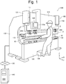
- the management system 190 is provided with a press brake 100 configured to perform bending and the like of a plate material to be processed (workpiece W), and a management server device 140 configured to manage information on the press brake 100.
- the press brake 100 and the management server device 140 of the management system 190 are connected to each other via a communication network 180 such as the Internet in a data-communicable manner.
- the communication network 180 includes, for example, a line that can be securely connected, such as a mobile phone network, a public line network, a LAN, a WAN, and a VPN (Virtual Private Network).
- a terminal device such as a tablet computer for operating and controlling the press brake may be connected to the communication network 180.
- "be connected” does not necessarily mean being physically connected by wiring or the like, but means that data and a signal can be transmitted and received between the respective components such as the press brake 100 and the management server device 140 regardless of being wired or wireless.
- the press brake 100 of the management system 190 has side plates 130 on both sides of the machine main body. Hydraulic cylinders 131, 132 serving as ram drive sources are provided at the upper parts of the side plates 130, and the upper table 110 is attached via the hydraulic cylinders 131, 132. A punch holder 300 is attached to the upper table 110 by a clamp jaw 200. A punch P, which is an upper tool, is mounted in the punch holder 300.
- the upper table 110 is provided with, for example, a control unit 145 (see Figure 2 ) configured to control the entire press brake 100, and an operation panel 133 of the control unit 145 in a movable manner.
- the control unit 145 can not only control the operation of the hydraulic cylinders 131, 132 but also manage a predictor of an occurrence of an abnormality in the hydraulic circuit 150 of each of the hydraulic cylinders 131, 132 (see Figure 2 ) .
- a display screen 133a of the operation panel 133 displays, for example, an order of bending of the workpiece W that is calculated by an automatic programming device, and various information on a tool consisting of the punch P and a die D to be used according to this order of bending.
- a lower table 120 is disposed at the lower parts of the side plates 130, and the die D, which is a lower tool, is mounted on the lower table 120 via a die holder 134.
- the press brake 100 is a descending press brake that moves the upper table 110 in a vertical direction with respect to the lower table 120 that is fixed.
- a linear scale 111 is connected to the upper table 110 as a position detector configured to detect position information of the upper table 110 in a moving direction (vertical direction).
- the press brake 100 shown in Figure 1 is configured, for example, such that the operation of a foot pedal 136 by an operator S causes the upper table 110 to move in a vertical direction relative to the lower table 120. Specifically, the operator S first presses the workpiece W against a butting body 135 of a back gauge arranged behind the lower table 120 for positioning. Subsequently, when the foot pedal 136 is depressed, the above-described hydraulic cylinders 131, 132 start to operate and lower the upper table 110. Then, the workpiece W is bent in cooperation of the punch P and the die D.
- the management server device 140 of the management system 190 is, for example, a server device managed by the manufacturer of the press brake, which is configured to be able to monitor an operation status and the like of the press brake 100 in real time.
- the management server device 140 can perform predictor management of the press brake 100 by not only calculating and storing control-related information including various operation information of the press brake 100 by itself, but also obtaining these pieces of information from the press brake 100.
- the predictor management in the present embodiment can be implemented in the entire management system 190 provided with the management server device 140 as described above. Note that, however, the predictor management in the present embodiment can also be implemented in the press brake 100 alone. Accordingly, hereinafter, description will be given mainly on the predictor management in the press brake 100 alone, but the present invention is not limited to this. Note that the present embodiment can be widely used for a machine tool that makes use of a hydraulic cylinder other than the press brake 100 shown in Figure 1 .
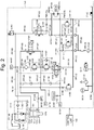
- Figure 2 shows the hydraulic cylinder 131, the hydraulic circuit 150 of the hydraulic cylinder 131, and the control unit 145 configured to control the hydraulic circuit 150. Since the hydraulic circuit of the hydraulic cylinder 132 is the same as the hydraulic circuit 150, the description thereof will be omitted.
- the hydraulic cylinder 131 of the press brake 100 has a piston 131a, a rod 131b mounted in the piston 131a, a substantially cylindrical cylinder tube 131c encompassing the piston 131a and the rod 131b, and a cylinder head 131d covering an upper portion of the cylinder tube 131c.
- the hydraulic circuit 150 is provided with a fluid pump PM101 configured to circulate hydraulic oil throughout the hydraulic circuit 150 and an AC servomotor MT101 configured to rotationally drive the fluid pump PM101.
- the fluid pump PM101 is a bidirectional pump.
- a forward direction the direction of the fluid pump PM101 from a primary side PM101a to a secondary side PM101b
- a reverse direction the direction of the fluid pump PM101 from a primary side PM101a to a secondary side PM101b
- a reverse direction the opposite direction from the secondary side PM101b to the primary side PM101a
- the primary side PM101a of the fluid pump PM101 is connected to a port A leading to an upper cylinder chamber 131e of the hydraulic cylinder 131 via a piping PP101, a directional control valve V101, and a piping PP102.
- the directional control valve V101 is, for example, a 4-port 2-position valve. At a position a, the directional control valve V101 is opened between a port A and a port T and opened between a port B and a port P. On the other hand, at a position b, the directional control valve V101 is opened between the port A and the port P and opened between the port B and the port T.
- the piping PP101 connects the primary side PM101a of the fluid pump PM101 and the port T of the directional control valve V101.
- the piping PP102 connects the port A of the directional control valve V101 and the port A of the hydraulic cylinder 131.
- the piping PP102 is provided with a pressure switch E101 and a pressure gauge M101.
- the pressure gauge M101 measures the hydraulic pressure of the hydraulic oil in the upper cylinder chamber 131e of the hydraulic cylinder 131.
- the secondary side PM101b of the fluid pump PM101 is connected to a port B leading to a lower cylinder chamber 131f of the hydraulic cylinder 131 via a piping PP103, a check valve V102, a piping PP104, a check valve V103, and a piping PP105.
- the piping PP103 is provided with a volume E103 connected via an orifice E102, and a pressure gauge M102.
- the pressure gauge M102 measures the hydraulic pressure of the hydraulic oil of the secondary side PM101b of the fluid pump PM101.
- the piping PP105 is provided with a pressure gauge M103.
- the pressure gauge M103 measures the hydraulic pressure of the hydraulic oil in the lower cylinder chamber 131f of the hydraulic cylinder 131.
- a pressure gauge M151 is provided to the piping PP104 and a piping PP107 that will be described later.
- the pressure gauge M151 measures the hydraulic pressure of the hydraulic oil downstream of a pressure control valve V105 as a first pressure control valve that will be described later. Then, surplus hydraulic oil in the fluid pump PM101 is discharged from a drain opening PM101c to an oil tank E104.
- the piping PP105 of the hydraulic circuit 150 is also connected to the piping PP104 through a path from a piping PP106, a directional control valve V104, to the piping PP107.
- the directional control valve V104 is, for example, a 2-port 2-position valve, and is opened between a port A and a port B at a position a, and closed between the port A and the port B at a position b.
- the piping PP106 connects the piping PP105 and the port A of the directional control valve V104.
- the piping PP107 connects the port B of the directional control valve V104 and the piping PP104.
- a pressure control unit U101 configured to control the back pressure of the hydraulic oil on the port B side of the hydraulic cylinder 131 is provided between the piping PP106 and the piping PP107 in parallel with the directional control valve V104.
- the pressure control unit U101 has a piping PP108, a filter E105, a piping PP109, a pressure control valve V105, and a piping PP110 each connected from the piping PP106 to the piping PP107.
- the piping PP105 is connected to the oil tank E104 via a piping PP111 provided with an orifice E106, a pressure control valve V106, a piping PP112, and a piping PP113.
- the piping PP107 is connected to the piping PP113 via a piping PP114, a pressure control valve V107, a piping PP115, a directional control valve V108, and a piping PP116.
- the directional control valve V108 is, for example, a 4-port 2-position valve. At a position a, the directional control valve V108 is opened between a port A and a port T and opened between a port B and a port P. On the other hand, at a position b, the directional control valve V108 is opened between the port A and the port P and closed between the port B and the port T.
- the piping PP115 connects the pressure control valve V107 and the directional control valve V108.
- the piping PP116 connects the port T of the directional control valve V108 and the piping PP113.
- the piping PP103 is connected to the oil tank E104 via a piping PP117, a check valve V109, a piping PP118, and a filter E107.
- the piping PP117 is connected to the oil tank E104 via a piping PP119, a pressure control valve V110, a piping PP120, and the piping PP113.
- the piping PP101 is connected to the oil tank E104 via a piping PP121, a check valve V111, a piping PP122, the piping PP118, and the filter E107.
- the piping PP121 is connected to the oil tank E104 via a piping PP125, a pressure control valve V112, a piping PP126, a piping PP123, and the piping PP113.
- the port B of the directional control valve V101 is connected to the oil tank E104 via the piping PP123 and the piping PP113.
- the port B of the directional control valve V101 is connected to the port P of the directional control valve V101 via the piping PP123 and a piping PP124 provided with an orifice E108.
- the upper cylinder chamber 131e of the hydraulic cylinder 131 is connected from the cylinder head 131d thereof to an oil tank E109 via a piping PP127, a prefill valve V113, and a piping PP128.
- the prefill valve V113 is opened by a pilot signal PL101 supplied from the directional control valve V108.
- the pilot signal PL101 is supplied from the port A of the directional control valve V108 at the position b via the piping PP103, a piping PP129, and the port P of the directional control valve V108.
- the oil tank E104 is provided with a magnet E110, a float switch E111, an air breather E112, and an oil level gauge M104. The above is the configuration of the hydraulic circuit 150 according to the present embodiment.
- the directional control valve V104 is switched to the position b by the control unit 145. Thereby, a self-weight of the upper table 110 is supported by the check valve V103, the directional control valve V104, the pressure control valve V105, and the pressure control valve V106. Note that the operation of the fluid pump PM101 is stopped in this situation.
- the pressure applied to the rod 131b of the hydraulic cylinder 131 gradually decreases to be the self-weight pressure of the upper table 110 due to leakage, flow rate loss, and pressure loss of the hydraulic oil in the respective valves from V103 to V106, the hydraulic cylinder 131, and the like.
- the leakage amount of the hydraulic oil varies depending on the individual specificity of a device.
- the directional control valve V101, the directional control valve V104, and the directional control valve V108 are switched to the positions a, respectively, by the control unit 145. Thereby, a path is opened from the port B of the hydraulic cylinder 131, via the directional control valve V104, the pressure control valve V107, the directional control valve V108, the secondary side PM101b of the fluid pump PM101, the primary side PM101a of the fluid pump PM101, and the directional control valve V101, to the port A of the hydraulic cylinder 131.
- the hydraulic oil is caused to flow in the reverse direction by the fluid pump PM101. Then, the hydraulic oil is drained from the lower cylinder chamber 131f of the hydraulic cylinder 131 through the above path, and the upper table 110 starts to lower by its self-weight. On the other hand, a negative pressure is generated in the upper cylinder chamber 131e of the hydraulic cylinder 131, and the negative pressure causes a large amount of hydraulic oil to be supplied from the oil tank E109 to the upper cylinder chamber 131e via the prefill valve V113. As a result, the upper table 110 lowers at a high speed.
- the control unit 145 switches the directional control valve V104 to the position b to close the flow path.
- the hydraulic oil flowing through the directional control valve V104 from the port B of the hydraulic cylinder 131 starts to flow through the pressure control valve V107 via the pressure control valve V105, which opens a path from the port B of the hydraulic cylinder 131, via the pressure control valve V105, the pressure control valve V107, the directional control valve V108, the secondary side PM101b of the fluid pump PM101, the primary side PM101a of the fluid pump PM101, and the directional control valve V101, to the port A of the hydraulic cylinder 131.
- the hydraulic oil is supplied to the fluid pump PM101 from the oil tank E104 via the filter E107 and the check valve V109.
- the hydraulic oil is supplied from the fluid pump PM101 to the upper cylinder chamber 131e of the hydraulic cylinder 131 via the directional control valve V101.
- the directional control valve V108 is switched to the position b by the control unit 145. Then, the hydraulic oil is caused to flow in the forward direction by the fluid pump PM101. Thereby, the hydraulic oil is supplied from the oil tank E104 to the lower cylinder chamber 131f of the hydraulic cylinder 131 via the filter E107, the primary side PM101a of the fluid pump PM101, the secondary side PM101b of the fluid pump PM101, the piping PP103, the check valve V102, and the check valve V103.
- the pilot signal PL101 is supplied from the port A of the directional control valve V108 to the prefill valve V113.
- the hydraulic oil in the upper cylinder chamber 131e of the hydraulic cylinder 131 is discharged to the oil tank E109 via the prefill valve V113.
- a negative pressure is generated in the piston 131a, and the upper table 110 is elevated.
- the self-weight of the upper table 110 cannot be sufficiently supported, and a malfunction occurs such as being unable to stop, or dropping at a speed exceeding a designed value. Further, if a difference is generated between the operation of the hydraulic circuit 150 of the hydraulic cylinder 131 and the operation of the hydraulic circuit (not shown) of the hydraulic cylinder 132, the upper table 110 is inclined, which significantly affects the processing of the workpiece W.
- the predictor of an occurrence of an abnormality in the hydraulic circuit 150 is managed in advance by the control unit 145.
- control unit 145 is configured to determine a predictor of an occurrence of an abnormality while monitoring the state of the press brake 100 in real time, so as to make a proactive response to prevent an occurrence of an abnormality when the predictor of the occurrence of an abnormality is detected by the predictor determination.
- control unit 145 is able to execute not only a control in which a predictor is determined by using each predictor determination threshold value that will be described later, but also a control in which the press brake 100 is stopped in an emergency by determining an abnormality by using an abnormality determination threshold value for detecting an abnormality that has actually occurred.
- the predictor determination that can be performed by the control unit 145 includes a method in which a predictor of an occurrence of an abnormality in the pressure control unit U101 (the pressure control valve V105) of the hydraulic circuit 150 is determined based on (1) a moving speed (lowering speed) of the upper table 110, (2) the pressure at least upstream of the pressure control valve V105, and/or (3) a monitor signal of the pressure control valve V105. Note that various methods other than the method of the predictor determination described below can be adopted.
- the control unit 145 obtains the detected current position information of the upper table 110 in real time from the linear scale 111 connected to the upper table 110. Then, a lowering speed of the upper table 110 per unit time is calculated based on the obtained current position information.
- the control unit 145 determines a predictor of an occurrence of an abnormality in the control valve V105 by comparing the calculated lowering speed with a preset predictor determination threshold value, and then by determining whether or not the lowering speed exceeds the predictor determination threshold value.
- the predictor determination threshold value is set to a value that is detected earlier than the abnormality determination threshold value, that is, a value lower than the abnormality determination threshold value.
- the predictor determination can be performed in a shorter time and in a more accurate manner than the determination simply with a lowering amount of the upper table 110.
- the upper table 110 is inevitably lowered due to its self-weight although the lowering is slow and minute.
- the control unit 145 may determine a predictor of an occurrence of an abnormality by monitoring a self-weight drop amount of the upper table 110 during the stopping and the bending lowering of the upper table 110. In this case, if the self-weight drop amount of the upper table 110 is larger than the design-wise allowable self-weight drop amount (the set predictor determination threshold value), it can be determined that an abnormality may occur. In this case, the larger the self-weight drop amount of the upper table 110, the more leakage of the hydraulic oil is to be recognized in the hydraulic circuit 150.
- the predictor determination threshold value is set to a value that is detected earlier than the abnormality determination threshold value, that is, a value lower than the abnormality determination threshold value. Note that when monitoring the self-weight drop amount of the upper table 110, it is also possible to determine, for example, the timing of replacing the hydraulic oil and the like based on the relationship between the monitor data and the past operation information.
- control unit 145 determines a predictor of an occurrence of an abnormality in the pressure control valve V105 by monitoring in real time an indicated value of the pressure gauge M103 of the hydraulic circuit 150, that is, the hydraulic pressure of the hydraulic oil upstream of the pressure control valve V105, and then by detecting that the indicated value (hydraulic pressure) has fallen below a preset predictor determination threshold value.
- a method may be adopted in which a predictor of an occurrence of an abnormality is determined by monitoring in real time a difference in the indicated value between the pressure gauge M103 and the pressure gauge M151 of the hydraulic circuit 150, that is, a difference in the hydraulic pressure of the hydraulic oil before and after the pressure control valve V105, and then by comparing this difference in the hydraulic pressure with a preset predictor determination threshold value.
- the predictor determination threshold value is set to a value that is detected earlier than the abnormality determination threshold value, that is, a value higher than the abnormality determination threshold value. In these methods, it is also possible to perform accurate predictor determination. In addition, according to these methods, it is possible to predict an occurrence of an abnormality in the pressure control valve V105.
- a pressure control valve with a monitoring function for detecting an abnormality in the valve is used as the pressure control valve V105.
- the control unit 145 determines a predictor of an occurrence of an abnormality in the pressure control valve V105 based on a monitor signal indicating a position in the valve, which is transmitted by the monitoring function of the pressure control valve V105.
- the determination condition for the predictor determination is set to be more relaxed than the condition for the abnormality determination so that the predictor determination is performed earlier than the abnormality determination. In the method as described above, it is also possible to perform accurate predictor determination.
- control unit 145 is also capable of performing composite predictor determination in which various types of predictor determination described above are combined.
- the control unit 145 may be configured to perform the predictor determination of the above (1) in combination with the predictor determination of the above (2) or (3).
- this composite predictor determination while predicting an occurrence of an abnormality in the entire hydraulic circuit 150 by the predictor determination of the above (1), it is possible to determine, by the predictor determination of the above (2) or (3), whether or not the position where an abnormality may occur is the pressure control valve V105.
- the predictor determination of the above (1) enables a predictor of an occurrence of an abnormality in the entire hydraulic circuit 150 to be determined, thereby making it possible to ensure safety and stable operability.
- the proactive response that can be taken by the control unit 145 when a predictor of an occurrence of an abnormality is detected includes a response in which a predictor of an abnormality is reported in the press brake 100, a response in which a predictor of an abnormality is reported to the management server device 140, and/or a response in which an occurrence of an abnormality is prevented by a duplex circuit operation that will be described later.
- the control unit 145 of the press brake 100 notifies the operator S or the like of a predictor of the abnormality by sounding an alarm or displaying a message to that effect on the display screen 133a of the operation panel 133 before the press brake 100 actually applies an emergency stop.
- control unit 145 of the press brake 100 transmits the result of the predictor determination to the management server device 140 together with or instead of the report on the predictor.
- the control unit 145 of the press brake 100 transmits the result of the predictor determination to the management server device 140 together with or instead of the report on the predictor.
- the control unit 145 of the press brake 100 can perform the duplex circuit operation that will be described later together with at least one of the reporting to the operator S and the reporting to the management server device 140 or instead of such reporting.
- this duplex circuit operation since the pressure control valve in which an abnormality has been predicted can be separated from the hydraulic circuit, a failure such as an emergency stop can be prevented in advance.
- a part in which an abnormality may occur is a pressure control valve, it is possible to promptly take measures such as arranging replacement parts.
- the above-described predictor management (the predictor determination and the proactive response) is performed in a state in which a table on a movable side, which is the upper table 110 in the present embodiment, is stopped.
- the above-described predictor management can be performed by automatic operation or by manual operation of the operator.
- a predetermined time difference (time lag) from the power-off operation of the operator to the actual powered-off state of the press brake 100 may be provided, so as to perform the above-described predictor determination automatically within the time lag.
- time lag time difference from the power-off operation of the operator to the actual powered-off state of the press brake 100
- the predictor determination can be performed automatically.
- the shutdown may be cancelled to take the above-described proactive response, or the above-described proactive response may be performed at the next startup.
- the predictor management (the predictor determination and the proactive response) by the control unit 145 can be performed 24 hours a day. That is, generally, when the main power supply is turned off after the press brake 100 is in a so-called ram lock state, for example, after the operation is completed, it is difficult to perform, for example, the predictor determination by the above methods (1) to (3) and the above proactive response.
- the press brake 100 is provided with the sub-battery and is configured to be able to secure the electric power from the sub-battery at least for the control unit 145 while the main power is off, it is possible to configure the predictor management in a sustainable manner by monitoring the state of the hydraulic circuit 150, whether it is during the hours of operation or it is during the hours of non-operation.
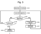
- Figure 3 is a first operation example, which is an example in which the control unit 145 determines a predictor of an occurrence of an abnormality in the hydraulic circuit 150 and reports to the operator S at the site, the service staff in a remote place, or the like when the occurrence of an abnormality is predicted.
- Step S102 when the operation of the press brake 100 that has been normally operated is stopped in a manner of the above-described "the stopping of the upper table" in Step S101, the control unit 145 performs predictor determination in Step S102 until the operation is restored.
- the predictor determination of Step S102 it is monitored whether or not an occurrence of an abnormality is predicted in the pressure control unit U101 (the pressure control valve V105) by using the above-described (1) to (3) and other methods (Step S103).
- Step S103 if the occurrence of an abnormality is not predicted (NO in Step S103), the predictor determination is continuously performed until the operation is restored (NO in Step S104). Then, when the operation is restored (YES in Step S104), the predictor determination is discontinued and the normal operation is resumed (Step S105).
- Step S103 if the occurrence of an abnormality is predicted (YES in Step S103), the control unit 145 transmits abnormality prediction information indicating that the abnormality has been predicted, for example, to the management server device 140 via the communication network 180 (Step S106), which causes the press brake 100 itself or the management server device 140 that has received the abnormality prediction information to make a proactive response (Step S107). Thereafter, the predictor determination is continuously performed until the operation is restored.
- the proactive response in Step S106 includes various actions that can be taken before an abnormality actually occurs.
- the proactive response includes reporting the predictor of an abnormality to the operator S or the like who is at the site by sounding an alarm of the press brake 100, or displaying a message to that effect on the display screen 133a of the operation panel 133.
- another proactive response includes transmitting the result of the predictor determination to the management server device 140 before the press brake 100 actually stops in an emergency or an alarm is sounded, so as to report to the service staff or the maintenance contractor in a remote place via the management server device 140 so that dispatchment of the service staff or the maintenance contractor to the site is arranged and measures such as replacement of parts are taken.
- the above predictor determination is described as being performed on the side of the press brake 100, but the present invention is not limited to this.
- the above predictor determination may be performed on the side of the management server device 140.
- control unit 145 or the management server device 140 of the press brake 100 can determine a predictor of an occurrence of an abnormality such as mixing of contamination in the hydraulic circuit 150. Therefore, it is possible to make an appropriate proactive response before the operation of the press brake 100 is completely stopped.
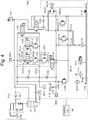
- the hydraulic circuit 150A has a pressure control unit U101A in place of the pressure control unit U101.
- the pressure control unit U101A has the filter E105 and the pressure control valve V105 in the same manner as the pressure control unit U101, as well as a directional control valve V152 provided upstream of the pressure control valve V105, a directional control valve V153 provided in parallel to the directional control valve V152 and the pressure control valve V105, and a pressure control valve V154 as a second pressure control valve.
- the directional control valve V152 is a 2-port 2-position valve configured to control an inflow of the hydraulic oil into the pressure control valve V105, and is opened between a port A and a port B at a position a, and closed between the port A and the port B at a position b.
- the directional control valve V153 is a 2-port 2-position valve configured to control an inflow of the hydraulic oil into the pressure control valve V154, and is opened between a port A and a port B at a position a, and closed between the port A and the port B at a position b.
- the port A of the directional control valve V153 is connected to a piping PP109 between the filter E105 and the directional control valve V152 via a piping PP152.
- the port B of the directional control valve V153 is connected to a pressure control valve V154 via a piping PP153.
- the directional control valves (the directional control valve V152 and the directional control valve V153) capable of switching between opening and closing between the port A and the port B are provided upstream of the pressure control valve V105 and the pressure control valve V154, respectively, but the present invention is not limited to this.
- one directional control valve (not shown) capable of switching between a state of communicating with the pressure control valve V105 and a state of communicating with the pressure control valve V154 may be provided upstream of the pressure control valve V105 and the pressure control valve V154.
- the hydraulic circuit 150A can perform the duplex circuit operation, in addition to the stopping, the self-weight lowering, the lowering bending, and the elevation or the forcible elevation of the upper table 110 of the hydraulic circuit 150.
- This duplex circuit operation is an operation in which the back pressure of the hydraulic oil on the port B side of the hydraulic cylinder 131 is controlled by the pressure control valve V154 in place of the pressure control valve V105 when the pressure control valve V105 is clogged with contamination.
- the directional control valve V152 of the pressure control unit U101A is at the position a, and the directional control valve V153 thereof is at the position b.
- the hydraulic pressure in the lower cylinder chamber 131f of the hydraulic cylinder 131 is controlled by the pressure control valve V105 via the filter E105 and the directional control valve V152.
- the directional control valve V152 and the directional control valve V153 are switched to the position b and the position a, respectively.
- the control body of the hydraulic pressure of the lower cylinder chamber 131f of the hydraulic cylinder 131 can be switched from the pressure control valve V105 to the pressure control valve V154.
- the duplex circuit operation as described above is utilized, it is possible to immediately restore the hydraulic circuit 150A if a predictor is detected that the pressure control valve V105 may be clogged with contamination or even if the pressure control valve V105 is actually clogged with contamination.
- the duplex circuit operation may be started not only by the control by the control unit 145 but also by an instruction of the operator S.
- Figure 5 is an operation example of the duplex circuit operation as a second operation example, which is an example in which the control unit 145 determines a predictor of an occurrence of an abnormality in the hydraulic circuit 150A and causes the duplex circuit operation to be performed when the occurrence of an abnormality.is predicted.
- Step S122 when the operation of the press brake 100 that has been normally operated is stopped in a manner of the above-described "the stopping of the upper table", the control unit 145 performs predictor determination in Step S122 until the operation is restored.
- the predictor determination is continuously performed until the operation is restored (NO in Step S124).
- the predictor determination is discontinued and the normal operation is resumed (Step S125).
- the duplex circuit operation is performed in Step S126.
- the directional control valve V152 is switched from the position a to the position b, and the directional control valve V153 is switched from the position b to the position a, respectively.
- the control body of the hydraulic pressure of the hydraulic oil in the lower cylinder chamber 131f of the hydraulic cylinder 131 is switched from the pressure control valve V105 to the pressure control valve V154.
- the predictor determination is continuously performed until the operation is restored (NO in Step S124).
- the predictor determination is discontinued and the normal operation is resumed (Step S125).
- Figure 6 is an operation example in which the above first operation example and second operation example are combined.
- Step S142 the control unit 145 performs predictor determination in Step S142 until the operation is restored.
- the predictor determination is continuously performed until the operation is restored (NO in Step S144).
- the predictor determination is discontinued and the normal operation is resumed (Step S145).
- the duplex circuit operation as described above is performed (Step S146), and the hydraulic circuit 150A is restored.
- Step S147 the same predictor determination as in Step S142 is performed in order to confirm that measures have been taken by the duplex circuit operation in Step S146.
- the control unit 145 transmits abnormality prediction information to the management server device 140, so that the press brake 100 or the management server device 140 makes a proactive response such as reporting or arranging replacement of parts (not shown).
- Step S144 the predictor determination is continuously performed until the operation is restored (NO in Step S149).
- Step S149 the predictor determination is discontinued and the normal operation is resumed (Step S150).
- Step S148 if the occurrence of an abnormality is predicted (YES in Step S148), it is determined that the cause of the occurrence of an abnormality predicted in the hydraulic circuit 150A has not been resolved, and the process proceeds to Step S151.
- the control unit 145 transmits the abnormality prediction information to the management server device 140. This causes the press brake 100 or the management server device 140 to make a proactive response (Step S152). Thereafter, the predictor determination is continuously performed until the operation is restored.
- the one pressure control valve V105 (or the pressure control valve V154) is clogged with contamination, it is possible to control the back pressure of the hydraulic oil on the port B side of the hydraulic cylinder 131 by the other pressure control valve V154 (or the pressure control valve V105) in an instant manner by performing the duplex circuit operation. That is, according to the present embodiment, by combining the reporting and the duplex circuit operation in the predictor management, it is possible to provide the press brake and the management system that can be restored over a short period of time even if a malfunction of the hydraulic circuit 150A has occurred due to mixing of contamination or the like. In addition, by determining whether or not the duplex circuit operation has resolved the predictor determination, it is possible to promptly and easily specify whether or not the position where an abnormality may occur is a pressure control valve, which enables arrangements such as replacement of parts to be promptly made.
- the predictor determination is performed based on the lowering speed or the like of the upper table 110a of a descending press brake, in which the upper table 110 of the press brake 100 moves with respect to the lower table 120.
- This predictor determination can be also performed based on the falling speed or the like of the lower table 120 of an ascending press brake when the ascending press brake is stopped, in which the lower table 120 moves with respect to the upper table 110.
- Various aspects are possible as long as the predictor of an occurrence of an abnormality in the hydraulic pressure circuits 150, 150A of the hydraulic cylinders 131, 142 can be managed.
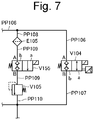
- a block valve V155 may be provided upstream of the pressure control valve V105 so that the block valve V155 regulates the flow of the hydraulic oil.
- a direction switching valve capable of switching between a conducting state and a non-conducting state can be adopted.
- the block valve V155 provided immediately before the pressure control valve V105 can regulate the hydraulic oil to flow normally. As a result, it is possible to prevent in advance a failure such as an alarm report or an emergency stop due to the abnormality in the pressure control valve V105.
- the block valve V155 in addition to the above-described use mode of the block valve V155, the block valve V155 can be utilized, for example, as a new option of the above-described proactive response. That is, according to the hydraulic circuit as described above, when an occurrence of an abnormality in the pressure control valve V105 is predicted in the above-described predictor determination, and if the block valve V155 is switched to the non-conducting state, it is possible to regulate the flow of the hydraulic oil without using the control valve V105 in which the occurrence of an abnormality is predicted, thereby making it possible to prevent the occurrence of an abnormality in advance,
Landscapes
- Engineering & Computer Science (AREA)
- Mechanical Engineering (AREA)
- Bending Of Plates, Rods, And Pipes (AREA)
- Control Of Presses (AREA)
- Fluid-Pressure Circuits (AREA)
Applications Claiming Priority (2)
| Application Number | Priority Date | Filing Date | Title |
|---|---|---|---|
| JP2018174789A JP6701294B2 (ja) | 2018-09-19 | 2018-09-19 | プレスブレーキ及び管理システム |
| PCT/JP2019/032859 WO2020059411A1 (ja) | 2018-09-19 | 2019-08-22 | プレスブレーキ及び管理システム |
Publications (3)
| Publication Number | Publication Date |
|---|---|
| EP3854496A1 true EP3854496A1 (de) | 2021-07-28 |
| EP3854496A4 EP3854496A4 (de) | 2021-11-17 |
| EP3854496B1 EP3854496B1 (de) | 2023-04-12 |
Family
ID=69887716
Family Applications (1)
| Application Number | Title | Priority Date | Filing Date |
|---|---|---|---|
| EP19863820.7A Active EP3854496B1 (de) | 2018-09-19 | 2019-08-22 | Abkantpresse und verwaltungssystem |
Country Status (5)
| Country | Link |
|---|---|
| US (1) | US11872620B2 (de) |
| EP (1) | EP3854496B1 (de) |
| JP (1) | JP6701294B2 (de) |
| CN (1) | CN112739470B (de) |
| WO (1) | WO2020059411A1 (de) |
Families Citing this family (1)
| Publication number | Priority date | Publication date | Assignee | Title |
|---|---|---|---|---|
| CN113145697B (zh) * | 2021-04-18 | 2022-06-03 | 南京盛大重工机械有限公司 | 一种单伺服泵控电液折弯机 |
Family Cites Families (16)
| Publication number | Priority date | Publication date | Assignee | Title |
|---|---|---|---|---|
| JPS61232100A (ja) * | 1985-04-06 | 1986-10-16 | Toyota Motor Corp | 安定成形プレス条件設定方法およびその装置 |
| JPH0721282B2 (ja) | 1986-03-22 | 1995-03-08 | 油研工業株式会社 | 可変容量形ポンプ |
| US4930401A (en) | 1988-10-28 | 1990-06-05 | Ross Operating Valve Company | Valve system and arrangement for on-line valve replacement |
| JPH03184700A (ja) * | 1989-12-13 | 1991-08-12 | Amada Co Ltd | 油圧回路の異常圧検出装置 |
| JPH10193200A (ja) * | 1997-01-14 | 1998-07-28 | Komatsu Ltd | 油圧プレスの油圧回路故障診断装置及びその方法 |
| EP1228822B1 (de) | 1999-10-20 | 2005-08-17 | AMADA COMPANY, Ltd. | Abkantpresse und bewegungsverfahren des kolbens einer abkantpresse |
| JP4473990B2 (ja) | 1999-10-25 | 2010-06-02 | 株式会社アマダエンジニアリングセンター | プレスブレーキ |
| JP2001277000A (ja) * | 2000-03-29 | 2001-10-09 | Amada Eng Center Co Ltd | 液圧プレスにおける速度切換え弁の故障検出方法およびその装置 |
| WO2001066340A1 (fr) | 2000-03-06 | 2001-09-13 | Amada Company, Limited | Dispositif et procede de commande de l'arret d'une presse hydraulique et dispositif et procede de detection de perturbation provenant d'une valve selectrice de vitesse |
| CN102628738B (zh) * | 2012-03-26 | 2014-12-24 | 上海交通大学 | 厚板轧机agc伺服阀状态监测与故障诊断系统 |
| CN105339682B (zh) * | 2013-04-19 | 2017-06-13 | 派克汉尼芬公司 | 检测液压系统中的液压阀故障的方法 |
| JP6011875B2 (ja) * | 2013-07-08 | 2016-10-19 | Smc株式会社 | アクチュエータの異常検出システム |
| JP6147182B2 (ja) * | 2013-12-20 | 2017-06-14 | 株式会社堀場エステック | 流体制御弁 |
| JP2016031086A (ja) * | 2014-07-28 | 2016-03-07 | 株式会社不二越 | 油圧機器の故障診断装置 |
| JP7028541B2 (ja) * | 2015-07-17 | 2022-03-02 | コマツ産機株式会社 | プレスシステムおよびプレスシステムの制御方法 |
| DE112017002163A5 (de) * | 2016-04-25 | 2019-01-17 | MAE Maschinen- und Apparatebau Götzen GmbH | Hydraulische Achse für eine Presse |
-
2018
- 2018-09-19 JP JP2018174789A patent/JP6701294B2/ja active Active
-
2019
- 2019-08-22 US US17/275,467 patent/US11872620B2/en active Active
- 2019-08-22 CN CN201980061540.1A patent/CN112739470B/zh active Active
- 2019-08-22 EP EP19863820.7A patent/EP3854496B1/de active Active
- 2019-08-22 WO PCT/JP2019/032859 patent/WO2020059411A1/ja not_active Ceased
Also Published As
| Publication number | Publication date |
|---|---|
| WO2020059411A1 (ja) | 2020-03-26 |
| CN112739470B (zh) | 2023-03-31 |
| JP2020044550A (ja) | 2020-03-26 |
| EP3854496B1 (de) | 2023-04-12 |
| JP6701294B2 (ja) | 2020-05-27 |
| US11872620B2 (en) | 2024-01-16 |
| US20220048086A1 (en) | 2022-02-17 |
| EP3854496A4 (de) | 2021-11-17 |
| CN112739470A (zh) | 2021-04-30 |
Similar Documents
| Publication | Publication Date | Title |
|---|---|---|
| JP6112085B2 (ja) | 油圧圧下サーボ弁の故障診断方法および装置 | |
| CN107991077B (zh) | 一种水轮机调速器主配压阀故障诊断方法 | |
| US12186823B2 (en) | Controlling the flow of coolant to resistance welding electrodes | |
| CN201496748U (zh) | 润滑油站智能控制系统 | |
| CN108518243B (zh) | 一种综采工作面智能供液方法及系统 | |
| CN104635599A (zh) | 一种用于动设备的主动预防性维护方法、装置 | |
| JP2019094926A (ja) | 制御弁装置 | |
| EP3854496B1 (de) | Abkantpresse und verwaltungssystem | |
| CN105060055A (zh) | 电梯按钮故障检测及处理方法 | |
| CN105650061A (zh) | 一种带故障自诊断的液压缸位置跟随系统及控制方法 | |
| CN105883972B (zh) | 净水器的控制部件的自检方法 | |
| CN112066266B (zh) | 煤气柜运行控制方法、监控系统和电子设备 | |
| CN104697759A (zh) | 压力开关寿命检测工装 | |
| CN115660320A (zh) | 一种气动开关阀预测性维修诊断方法 | |
| CN102173177B (zh) | 一种太阳能层压机自动控制系统 | |
| CN104196694A (zh) | 混凝土泵实时监控方法及系统 | |
| CN203587338U (zh) | 压力开关寿命检测工装 | |
| CN203621109U (zh) | 冷轧液压辊缝控制压力检测冗余切换系统 | |
| CN115199952B (zh) | 过滤设备控制系统及方法 | |
| CN103676802A (zh) | 液压启闭机工作状态统计分析学习系统 | |
| CN201669169U (zh) | 一种重相油与轻相油分离用自动监控装置 | |
| WO2020188462A1 (en) | A performance monitoring system of a cnc machine | |
| JP3474786B2 (ja) | プロセス故障監視支援装置 | |
| CN105806598A (zh) | 一种液控蝶阀检测方法及报警系统 | |
| CN102981424A (zh) | 一种输出控制方法、装置及控制系统 |
Legal Events
| Date | Code | Title | Description |
|---|---|---|---|
| STAA | Information on the status of an ep patent application or granted ep patent |
Free format text: STATUS: THE INTERNATIONAL PUBLICATION HAS BEEN MADE |
|
| PUAI | Public reference made under article 153(3) epc to a published international application that has entered the european phase |
Free format text: ORIGINAL CODE: 0009012 |
|
| STAA | Information on the status of an ep patent application or granted ep patent |
Free format text: STATUS: REQUEST FOR EXAMINATION WAS MADE |
|
| 17P | Request for examination filed |
Effective date: 20210414 |
|
| AK | Designated contracting states |
Kind code of ref document: A1 Designated state(s): AL AT BE BG CH CY CZ DE DK EE ES FI FR GB GR HR HU IE IS IT LI LT LU LV MC MK MT NL NO PL PT RO RS SE SI SK SM TR |
|
| A4 | Supplementary search report drawn up and despatched |
Effective date: 20211020 |
|
| RIC1 | Information provided on ipc code assigned before grant |
Ipc: B21D 55/00 20060101ALI20211014BHEP Ipc: B21D 5/00 20060101ALI20211014BHEP Ipc: B30B 15/26 20060101ALI20211014BHEP Ipc: B30B 15/16 20060101ALI20211014BHEP Ipc: B30B 15/28 20060101ALI20211014BHEP Ipc: B21D 5/02 20060101AFI20211014BHEP |
|
| DAV | Request for validation of the european patent (deleted) | ||
| DAX | Request for extension of the european patent (deleted) | ||
| STAA | Information on the status of an ep patent application or granted ep patent |
Free format text: STATUS: EXAMINATION IS IN PROGRESS |
|
| 17Q | First examination report despatched |
Effective date: 20220718 |
|
| GRAP | Despatch of communication of intention to grant a patent |
Free format text: ORIGINAL CODE: EPIDOSNIGR1 |
|
| STAA | Information on the status of an ep patent application or granted ep patent |
Free format text: STATUS: GRANT OF PATENT IS INTENDED |
|
| INTG | Intention to grant announced |
Effective date: 20221221 |
|
| GRAS | Grant fee paid |
Free format text: ORIGINAL CODE: EPIDOSNIGR3 |
|
| GRAA | (expected) grant |
Free format text: ORIGINAL CODE: 0009210 |
|
| STAA | Information on the status of an ep patent application or granted ep patent |
Free format text: STATUS: THE PATENT HAS BEEN GRANTED |
|
| AK | Designated contracting states |
Kind code of ref document: B1 Designated state(s): AL AT BE BG CH CY CZ DE DK EE ES FI FR GB GR HR HU IE IS IT LI LT LU LV MC MK MT NL NO PL PT RO RS SE SI SK SM TR |
|
| REG | Reference to a national code |
Ref country code: GB Ref legal event code: FG4D |
|
| REG | Reference to a national code |
Ref country code: CH Ref legal event code: EP |
|
| REG | Reference to a national code |
Ref country code: DE Ref legal event code: R096 Ref document number: 602019027562 Country of ref document: DE |
|
| REG | Reference to a national code |
Ref country code: IE Ref legal event code: FG4D |
|
| REG | Reference to a national code |
Ref country code: AT Ref legal event code: REF Ref document number: 1559491 Country of ref document: AT Kind code of ref document: T Effective date: 20230515 |
|
| P01 | Opt-out of the competence of the unified patent court (upc) registered |
Effective date: 20230527 |
|
| REG | Reference to a national code |
Ref country code: LT Ref legal event code: MG9D |
|
| REG | Reference to a national code |
Ref country code: NL Ref legal event code: MP Effective date: 20230412 |
|
| REG | Reference to a national code |
Ref country code: AT Ref legal event code: MK05 Ref document number: 1559491 Country of ref document: AT Kind code of ref document: T Effective date: 20230412 |
|
| PG25 | Lapsed in a contracting state [announced via postgrant information from national office to epo] |
Ref country code: NL Free format text: LAPSE BECAUSE OF FAILURE TO SUBMIT A TRANSLATION OF THE DESCRIPTION OR TO PAY THE FEE WITHIN THE PRESCRIBED TIME-LIMIT Effective date: 20230412 |
|
| PG25 | Lapsed in a contracting state [announced via postgrant information from national office to epo] |
Ref country code: SE Free format text: LAPSE BECAUSE OF FAILURE TO SUBMIT A TRANSLATION OF THE DESCRIPTION OR TO PAY THE FEE WITHIN THE PRESCRIBED TIME-LIMIT Effective date: 20230412 Ref country code: PT Free format text: LAPSE BECAUSE OF FAILURE TO SUBMIT A TRANSLATION OF THE DESCRIPTION OR TO PAY THE FEE WITHIN THE PRESCRIBED TIME-LIMIT Effective date: 20230814 Ref country code: NO Free format text: LAPSE BECAUSE OF FAILURE TO SUBMIT A TRANSLATION OF THE DESCRIPTION OR TO PAY THE FEE WITHIN THE PRESCRIBED TIME-LIMIT Effective date: 20230712 Ref country code: ES Free format text: LAPSE BECAUSE OF FAILURE TO SUBMIT A TRANSLATION OF THE DESCRIPTION OR TO PAY THE FEE WITHIN THE PRESCRIBED TIME-LIMIT Effective date: 20230412 Ref country code: AT Free format text: LAPSE BECAUSE OF FAILURE TO SUBMIT A TRANSLATION OF THE DESCRIPTION OR TO PAY THE FEE WITHIN THE PRESCRIBED TIME-LIMIT Effective date: 20230412 |
|
| PG25 | Lapsed in a contracting state [announced via postgrant information from national office to epo] |
Ref country code: RS Free format text: LAPSE BECAUSE OF FAILURE TO SUBMIT A TRANSLATION OF THE DESCRIPTION OR TO PAY THE FEE WITHIN THE PRESCRIBED TIME-LIMIT Effective date: 20230412 Ref country code: PL Free format text: LAPSE BECAUSE OF FAILURE TO SUBMIT A TRANSLATION OF THE DESCRIPTION OR TO PAY THE FEE WITHIN THE PRESCRIBED TIME-LIMIT Effective date: 20230412 Ref country code: LV Free format text: LAPSE BECAUSE OF FAILURE TO SUBMIT A TRANSLATION OF THE DESCRIPTION OR TO PAY THE FEE WITHIN THE PRESCRIBED TIME-LIMIT Effective date: 20230412 Ref country code: LT Free format text: LAPSE BECAUSE OF FAILURE TO SUBMIT A TRANSLATION OF THE DESCRIPTION OR TO PAY THE FEE WITHIN THE PRESCRIBED TIME-LIMIT Effective date: 20230412 Ref country code: IS Free format text: LAPSE BECAUSE OF FAILURE TO SUBMIT A TRANSLATION OF THE DESCRIPTION OR TO PAY THE FEE WITHIN THE PRESCRIBED TIME-LIMIT Effective date: 20230812 Ref country code: HR Free format text: LAPSE BECAUSE OF FAILURE TO SUBMIT A TRANSLATION OF THE DESCRIPTION OR TO PAY THE FEE WITHIN THE PRESCRIBED TIME-LIMIT Effective date: 20230412 Ref country code: GR Free format text: LAPSE BECAUSE OF FAILURE TO SUBMIT A TRANSLATION OF THE DESCRIPTION OR TO PAY THE FEE WITHIN THE PRESCRIBED TIME-LIMIT Effective date: 20230713 Ref country code: AL Free format text: LAPSE BECAUSE OF FAILURE TO SUBMIT A TRANSLATION OF THE DESCRIPTION OR TO PAY THE FEE WITHIN THE PRESCRIBED TIME-LIMIT Effective date: 20230412 |
|
| PG25 | Lapsed in a contracting state [announced via postgrant information from national office to epo] |
Ref country code: FI Free format text: LAPSE BECAUSE OF FAILURE TO SUBMIT A TRANSLATION OF THE DESCRIPTION OR TO PAY THE FEE WITHIN THE PRESCRIBED TIME-LIMIT Effective date: 20230412 |
|
| REG | Reference to a national code |
Ref country code: DE Ref legal event code: R097 Ref document number: 602019027562 Country of ref document: DE |
|
| PG25 | Lapsed in a contracting state [announced via postgrant information from national office to epo] |
Ref country code: SK Free format text: LAPSE BECAUSE OF FAILURE TO SUBMIT A TRANSLATION OF THE DESCRIPTION OR TO PAY THE FEE WITHIN THE PRESCRIBED TIME-LIMIT Effective date: 20230412 |
|
| PG25 | Lapsed in a contracting state [announced via postgrant information from national office to epo] |
Ref country code: SM Free format text: LAPSE BECAUSE OF FAILURE TO SUBMIT A TRANSLATION OF THE DESCRIPTION OR TO PAY THE FEE WITHIN THE PRESCRIBED TIME-LIMIT Effective date: 20230412 Ref country code: SK Free format text: LAPSE BECAUSE OF FAILURE TO SUBMIT A TRANSLATION OF THE DESCRIPTION OR TO PAY THE FEE WITHIN THE PRESCRIBED TIME-LIMIT Effective date: 20230412 Ref country code: RO Free format text: LAPSE BECAUSE OF FAILURE TO SUBMIT A TRANSLATION OF THE DESCRIPTION OR TO PAY THE FEE WITHIN THE PRESCRIBED TIME-LIMIT Effective date: 20230412 Ref country code: EE Free format text: LAPSE BECAUSE OF FAILURE TO SUBMIT A TRANSLATION OF THE DESCRIPTION OR TO PAY THE FEE WITHIN THE PRESCRIBED TIME-LIMIT Effective date: 20230412 Ref country code: DK Free format text: LAPSE BECAUSE OF FAILURE TO SUBMIT A TRANSLATION OF THE DESCRIPTION OR TO PAY THE FEE WITHIN THE PRESCRIBED TIME-LIMIT Effective date: 20230412 Ref country code: CZ Free format text: LAPSE BECAUSE OF FAILURE TO SUBMIT A TRANSLATION OF THE DESCRIPTION OR TO PAY THE FEE WITHIN THE PRESCRIBED TIME-LIMIT Effective date: 20230412 |
|
| PLBE | No opposition filed within time limit |
Free format text: ORIGINAL CODE: 0009261 |
|
| STAA | Information on the status of an ep patent application or granted ep patent |
Free format text: STATUS: NO OPPOSITION FILED WITHIN TIME LIMIT |
|
| PG25 | Lapsed in a contracting state [announced via postgrant information from national office to epo] |
Ref country code: MC Free format text: LAPSE BECAUSE OF FAILURE TO SUBMIT A TRANSLATION OF THE DESCRIPTION OR TO PAY THE FEE WITHIN THE PRESCRIBED TIME-LIMIT Effective date: 20230412 |
|
| 26N | No opposition filed |
Effective date: 20240115 |
|
| REG | Reference to a national code |
Ref country code: CH Ref legal event code: PL |
|
| PG25 | Lapsed in a contracting state [announced via postgrant information from national office to epo] |
Ref country code: MC Free format text: LAPSE BECAUSE OF FAILURE TO SUBMIT A TRANSLATION OF THE DESCRIPTION OR TO PAY THE FEE WITHIN THE PRESCRIBED TIME-LIMIT Effective date: 20230412 |
|
| PG25 | Lapsed in a contracting state [announced via postgrant information from national office to epo] |
Ref country code: LU Free format text: LAPSE BECAUSE OF NON-PAYMENT OF DUE FEES Effective date: 20230822 |
|
| PG25 | Lapsed in a contracting state [announced via postgrant information from national office to epo] |
Ref country code: LU Free format text: LAPSE BECAUSE OF NON-PAYMENT OF DUE FEES Effective date: 20230822 Ref country code: CH Free format text: LAPSE BECAUSE OF NON-PAYMENT OF DUE FEES Effective date: 20230831 |
|
| PG25 | Lapsed in a contracting state [announced via postgrant information from national office to epo] |
Ref country code: SI Free format text: LAPSE BECAUSE OF FAILURE TO SUBMIT A TRANSLATION OF THE DESCRIPTION OR TO PAY THE FEE WITHIN THE PRESCRIBED TIME-LIMIT Effective date: 20230412 |
|
| REG | Reference to a national code |
Ref country code: BE Ref legal event code: MM Effective date: 20230831 |
|
| REG | Reference to a national code |
Ref country code: IE Ref legal event code: MM4A |
|
| PG25 | Lapsed in a contracting state [announced via postgrant information from national office to epo] |
Ref country code: SI Free format text: LAPSE BECAUSE OF FAILURE TO SUBMIT A TRANSLATION OF THE DESCRIPTION OR TO PAY THE FEE WITHIN THE PRESCRIBED TIME-LIMIT Effective date: 20230412 |
|
| PG25 | Lapsed in a contracting state [announced via postgrant information from national office to epo] |
Ref country code: IE Free format text: LAPSE BECAUSE OF NON-PAYMENT OF DUE FEES Effective date: 20230822 |
|
| PG25 | Lapsed in a contracting state [announced via postgrant information from national office to epo] |
Ref country code: IE Free format text: LAPSE BECAUSE OF NON-PAYMENT OF DUE FEES Effective date: 20230822 |
|
| PG25 | Lapsed in a contracting state [announced via postgrant information from national office to epo] |
Ref country code: BE Free format text: LAPSE BECAUSE OF NON-PAYMENT OF DUE FEES Effective date: 20230831 |
|
| PG25 | Lapsed in a contracting state [announced via postgrant information from national office to epo] |
Ref country code: BG Free format text: LAPSE BECAUSE OF FAILURE TO SUBMIT A TRANSLATION OF THE DESCRIPTION OR TO PAY THE FEE WITHIN THE PRESCRIBED TIME-LIMIT Effective date: 20230412 |
|
| PG25 | Lapsed in a contracting state [announced via postgrant information from national office to epo] |
Ref country code: BG Free format text: LAPSE BECAUSE OF FAILURE TO SUBMIT A TRANSLATION OF THE DESCRIPTION OR TO PAY THE FEE WITHIN THE PRESCRIBED TIME-LIMIT Effective date: 20230412 |
|
| PG25 | Lapsed in a contracting state [announced via postgrant information from national office to epo] |
Ref country code: CY Free format text: LAPSE BECAUSE OF FAILURE TO SUBMIT A TRANSLATION OF THE DESCRIPTION OR TO PAY THE FEE WITHIN THE PRESCRIBED TIME-LIMIT; INVALID AB INITIO Effective date: 20190822 |
|
| PG25 | Lapsed in a contracting state [announced via postgrant information from national office to epo] |
Ref country code: HU Free format text: LAPSE BECAUSE OF FAILURE TO SUBMIT A TRANSLATION OF THE DESCRIPTION OR TO PAY THE FEE WITHIN THE PRESCRIBED TIME-LIMIT; INVALID AB INITIO Effective date: 20190822 |
|
| PGFP | Annual fee paid to national office [announced via postgrant information from national office to epo] |
Ref country code: DE Payment date: 20250820 Year of fee payment: 7 |
|
| PGFP | Annual fee paid to national office [announced via postgrant information from national office to epo] |
Ref country code: IT Payment date: 20250825 Year of fee payment: 7 |
|
| PGFP | Annual fee paid to national office [announced via postgrant information from national office to epo] |
Ref country code: GB Payment date: 20250820 Year of fee payment: 7 |
|
| PGFP | Annual fee paid to national office [announced via postgrant information from national office to epo] |
Ref country code: FR Payment date: 20250828 Year of fee payment: 7 |
|
| PG25 | Lapsed in a contracting state [announced via postgrant information from national office to epo] |
Ref country code: TR Free format text: LAPSE BECAUSE OF FAILURE TO SUBMIT A TRANSLATION OF THE DESCRIPTION OR TO PAY THE FEE WITHIN THE PRESCRIBED TIME-LIMIT Effective date: 20230412 |