EP3854518A1 - Elektrisches antriebssystem für werkzeugmaschinen und betriebsverfahren dafür - Google Patents
Elektrisches antriebssystem für werkzeugmaschinen und betriebsverfahren dafür Download PDFInfo
- Publication number
- EP3854518A1 EP3854518A1 EP19862371.2A EP19862371A EP3854518A1 EP 3854518 A1 EP3854518 A1 EP 3854518A1 EP 19862371 A EP19862371 A EP 19862371A EP 3854518 A1 EP3854518 A1 EP 3854518A1
- Authority
- EP
- European Patent Office
- Prior art keywords
- spindle
- chuck
- clutch
- drive pulley
- unit
- Prior art date
- Legal status (The legal status is an assumption and is not a legal conclusion. Google has not performed a legal analysis and makes no representation as to the accuracy of the status listed.)
- Granted
Links
Images



Classifications
-
- B—PERFORMING OPERATIONS; TRANSPORTING
- B23—MACHINE TOOLS; METAL-WORKING NOT OTHERWISE PROVIDED FOR
- B23Q—DETAILS, COMPONENTS, OR ACCESSORIES FOR MACHINE TOOLS, e.g. ARRANGEMENTS FOR COPYING OR CONTROLLING; MACHINE TOOLS IN GENERAL CHARACTERISED BY THE CONSTRUCTION OF PARTICULAR DETAILS OR COMPONENTS; COMBINATIONS OR ASSOCIATIONS OF METAL-WORKING MACHINES, NOT DIRECTED TO A PARTICULAR RESULT
- B23Q5/00—Driving or feeding mechanisms; Control arrangements therefor
- B23Q5/02—Driving main working members
- B23Q5/04—Driving main working members rotary shafts, e.g. working-spindles
- B23Q5/043—Accessories for spindle drives
-
- B—PERFORMING OPERATIONS; TRANSPORTING
- B23—MACHINE TOOLS; METAL-WORKING NOT OTHERWISE PROVIDED FOR
- B23Q—DETAILS, COMPONENTS, OR ACCESSORIES FOR MACHINE TOOLS, e.g. ARRANGEMENTS FOR COPYING OR CONTROLLING; MACHINE TOOLS IN GENERAL CHARACTERISED BY THE CONSTRUCTION OF PARTICULAR DETAILS OR COMPONENTS; COMBINATIONS OR ASSOCIATIONS OF METAL-WORKING MACHINES, NOT DIRECTED TO A PARTICULAR RESULT
- B23Q16/00—Equipment for precise positioning of tool or work into particular locations not otherwise provided for
- B23Q16/02—Indexing equipment
- B23Q16/04—Indexing equipment having intermediate members, e.g. pawls, for locking the relatively movable parts in the indexed position
- B23Q16/043—Indexing equipment having intermediate members, e.g. pawls, for locking the relatively movable parts in the indexed position with a reciprocating or oscillating drive
-
- B—PERFORMING OPERATIONS; TRANSPORTING
- B23—MACHINE TOOLS; METAL-WORKING NOT OTHERWISE PROVIDED FOR
- B23B—TURNING; BORING
- B23B31/00—Chucks; Expansion mandrels; Adaptations thereof for remote control
- B23B31/02—Chucks
- B23B31/10—Chucks characterised by the retaining or gripping devices or their immediate operating means
- B23B31/12—Chucks with simultaneously-acting jaws, whether or not also individually adjustable
- B23B31/16—Chucks with simultaneously-acting jaws, whether or not also individually adjustable moving radially
- B23B31/16233—Jaws movement actuated by oblique surfaces of a coaxial control rod
- B23B31/16266—Jaws movement actuated by oblique surfaces of a coaxial control rod using mechanical transmission through the spindle
-
- B—PERFORMING OPERATIONS; TRANSPORTING
- B23—MACHINE TOOLS; METAL-WORKING NOT OTHERWISE PROVIDED FOR
- B23Q—DETAILS, COMPONENTS, OR ACCESSORIES FOR MACHINE TOOLS, e.g. ARRANGEMENTS FOR COPYING OR CONTROLLING; MACHINE TOOLS IN GENERAL CHARACTERISED BY THE CONSTRUCTION OF PARTICULAR DETAILS OR COMPONENTS; COMBINATIONS OR ASSOCIATIONS OF METAL-WORKING MACHINES, NOT DIRECTED TO A PARTICULAR RESULT
- B23Q5/00—Driving or feeding mechanisms; Control arrangements therefor
- B23Q5/02—Driving main working members
- B23Q5/04—Driving main working members rotary shafts, e.g. working-spindles
- B23Q5/10—Driving main working members rotary shafts, e.g. working-spindles driven essentially by electrical means
-
- B—PERFORMING OPERATIONS; TRANSPORTING
- B23—MACHINE TOOLS; METAL-WORKING NOT OTHERWISE PROVIDED FOR
- B23B—TURNING; BORING
- B23B2260/00—Details of constructional elements
- B23B2260/044—Clutches
-
- B—PERFORMING OPERATIONS; TRANSPORTING
- B23—MACHINE TOOLS; METAL-WORKING NOT OTHERWISE PROVIDED FOR
- B23B—TURNING; BORING
- B23B2270/00—Details of turning, boring or drilling machines, processes or tools not otherwise provided for
- B23B2270/48—Measuring or detecting
-
- B—PERFORMING OPERATIONS; TRANSPORTING
- B23—MACHINE TOOLS; METAL-WORKING NOT OTHERWISE PROVIDED FOR
- B23Q—DETAILS, COMPONENTS, OR ACCESSORIES FOR MACHINE TOOLS, e.g. ARRANGEMENTS FOR COPYING OR CONTROLLING; MACHINE TOOLS IN GENERAL CHARACTERISED BY THE CONSTRUCTION OF PARTICULAR DETAILS OR COMPONENTS; COMBINATIONS OR ASSOCIATIONS OF METAL-WORKING MACHINES, NOT DIRECTED TO A PARTICULAR RESULT
- B23Q2705/00—Driving working spindles or feeding members carrying tools or work
- B23Q2705/005—General aspects of driving arrangements in a lathe, e.g. indexing the spindle, devices for keeping the cutting speed constant, braking or reversing devices
Definitions
- the present disclosure relates to a machine tool, and more particularly, a machine tool electrical driving system and an operation method thereof capable of selectively transmitting power of a motor for driving a spindle in a lathe which machines a workpiece to a rotation system including a drawbar and a spindle for clamping or unclamping the workpiece, using a clutch device.
- a machine tool includes a workpiece and a machining tool, and when one of the two is fixed, the other rotates to machine a shape of the workpiece, and the machine tool can be divided into a lathe and a milling machine according to a rotating unit.
- the lathe is configured in such a way that the workpiece rotates in a state where the machining tool is stationary, and typically, includes a chuck for fixing the workpiece, a drawbar for driving the chuck, and a spindle for rotating the drawbar, the chuck, and the workpiece.
- a spindle is selectively connected to a housing and a drive element (for example, a drive pulley) through an operation of a clutch device, and a clamping operation (clamping operation mode) of the workpiece and a machining operation (spindle operation mode) of the workpiece are generally performed.
- a drive element for example, a drive pulley
- clamping operation clamping operation mode
- machining operation spindle operation mode
- the present disclosure is to solve the above problems, and an object of the present disclosure is to provide a machine tool electrical driving system and an operation method thereof capable of directly transmitting power of a spindle motor to a spindle through a drive pulley to improve power transmission efficiency.
- Another object of the present disclosure is to provide a machine tool electrical driving system and an operation method thereof capable of accurately coupling teeth of a serration of a clutch device when the position of the serration of the clutch unit is accurately detected in real time and an operation mode is switched.
- a machine tool electrical driving system including: a housing; a hollow tubular spindle extending in a front-rear direction in the housing and rotatably installed with respect to the housing; a drive pulley fixedly installed to the spindle outside a rear portion of the spindle; a spindle motor configured to rotate the drive pulley; a chuck installed in a front end portion of the spindle and having a jaw clamping a workpiece; a drawbar installed to be linearly movable inside the spindle in a front-rear direction so that a front end portion is connected to the chuck to be linearly movable with respect to the chuck but non-rotatable relative to the chuck in the front-rear direction; a motion conversion unit configured to receive a rotational force of the drive pulley and convert the rotation force into a forward-rearward motion of the drawbar; a chuck locking unit configured to restrain or release a rotary motion of the chuck
- the clutch unit may include a fixed member fixed to a rear surface of the chuck, a rotary member fixed to the front end portion of the spindle and rotatably connected to the fixed member, a fixed clutch fixed to a rear portion of the fixed member and having a front serration formed along a circumferential direction, a movable clutch installed to be movable in a front-rear direction in front of the rotary member and having a rear serration which restrains a relative rotation of the rotary member with respect to the fixed member while engaging with the front serration and is formed along the circumferential direction, and
- a clutch operation member configured to move the movable clutch in the front-rear direction.
- the clutch operation member may include a piston installed inside a piston accommodation groove formed in the fixed member and configured to push the movable clutch rearward while moving rearward by a pneumatic pressure applied to an inside of the piston accommodation groove, a clutch spring configured to apply an elastic force to the movable clutch forward, and a piston bearing disposed between the movable clutch and the piston to rotatably support the movable clutch with respect to the piston.
- the chuck locking unit may include a fixing pin installed to linearly reciprocate toward the chuck side in front of the housing, a distal end of the fixing pin being inserted into a locking groove formed on an outer peripheral surface of the fixed member or the chuck, and a pin actuator configured to linearly reciprocate the fixing pin.
- a pneumatic channel extending from the piston accommodation groove to the locking groove may be formed in the fixed member, an air supply channel that communicates with the pneumatic channel when the fixing pin is inserted into the locking groove may be formed in the fixing pin, and the air supply channel may be connected to an external air supply unit to supply air to the pneumatic channel.
- a lubricant channel configured to communicate with the locking groove may be formed in the fixed member
- a lubricant supply channel that communicates with the lubricant channel when the fixing pin is inserted into the locking groove may be formed in the fixing pin
- the lubricant supply channel may be connected to an external lubricant supply unit to supply a lubricant to the lubricant channel.
- the motion conversion unit may include a lead screw having an outer surface on which a screw thread is spirally formed and formed to be fixed to the drawbar, a carrier member having an inner peripheral surface on which a screw thread spirally coupled to the screw thread of the lead screw is formed and coupled to an outside of the lead screw, and a rotational force transmission unit configured to transmit a rotational force of the drive pulley to the carrier member.
- the rotational force transmission unit may include a ring-shaped drive member fixedly connected to the drive pulley and a plurality of drive pins installed in the drive member to protrude radially inward to transmit a rotational force to the carrier member, and a long hole-shaped backlash groove into which a distal end of the drive pin is inserted to move by a certain amount in a circumferential direction may be formed on an outer surface of the carrier member.
- the encoder unit may include a first encoder pulley installed in a rear portion of the drive pulley, a second encoder pulley rotatably installed in the housing, an encoding power transmission belt installed to be wound around the first encoder pulley and the second encoder pulley to transmit a rotational force of the first encoder pulley to the second encoder pulley, and an encoder axially coupled to a center portion of the second encoder pulley to detect a rotation position and configured to transmit a detected position signal to a controller that controls a rotation of the spindle motor.
- an operation method of the machine tool electrical driving system including: the following steps, that is, (S1) a step of rotating the drive pulley, the spindle, and the clutch unit according to a position information detected by the encoder unit to arrange the clutch unit coupled to the chuck locking unit at an initial position; (S2) a step of operating the chuck locking unit to fix the chuck to the housing; (S3) a step of operating the clutch unit to separate the spindle from the chuck so that the spindle is rotatable relative to the chuck; (S4) a step of applying power to the spindle motor and rotating the drive pulley, the spindle, the motion conversion unit in an unclamping direction so that the jaw unclamps the workpiece; (S5) a step of applying power to the spindle motor and rotating the drive pulley, the spindle, the motion conversion unit in a clamping direction so that the jaw clamps the workpiece; (S6) a step of rotating the drive pulley,
- the drive pulley that is connected to the spindle motor and receives the rotation force is fixed to the outer surface of the spindle, and thus, the rotational force of the drive pulley can be directly transmitted to the spindle. Therefore, it is possible to increase power transmission efficiency.
- the clutch unit is disposed in front of the spindle, and thus, the clutch unit and the spindle can be easily detached or attached as one module.
- positions of the drive pulley, the spindle, and the clutch unit coupled thereto are accurately detected by the encoder unit, and based on detected position information, when a spindle operation mode is switched to a clamping operation mode and the clamping operation mode is switched to the spindle operation mode, a position of the serration of the clutch unit can be accurately arranged, the serrations configured in the clutch unit can be accurately engaged with each other always, and a correct drive control can be performed in each operation mode.
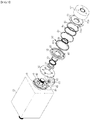
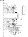
- a machine tool electrical driving system of the present disclosure includes a housing 10 that is fixedly installed in a main body of a machine tool, a hollow tubular spindle 20 that is rotatably installed with respect to the housing 10, a drive pulley 30 that is fixedly installed to the spindle 20 outside a rear portion of the spindle 20, a spindle motor (not illustrated) that rotates the drive pulley 30, a chuck C that is installed in a front end portion of the spindle 20 and has a jaw J clamping a workpiece, a drawbar 40 that is installed to be linearly movable inside the spindle 20 in a front-rear direction so that a front end portion is connected to the jaw J, a draw key 43 a draw key groove 42 that connect the drawbar 40 so that the drawbar 40 is linearly movable with respect to the chuck C but non-rotatable relative to the chuck C, a chuck locking unit that restrains or releases a
- the motion conversion unit includes a lead screw 41 that has an outer surface on which a screw thread is spirally formed and is fixedly formed in the drawbar 40, a carrier member 95 that has an inner peripheral surface on which a screw thread 95a spirally coupled to the screw thread of the lead screw 41 is formed and is coupled to an outside of the lead screw 41, and a rotational force transmission unit that a rotational force of the drive pulley 30 to the carrier member 95.
- the housing 10 is formed in an empty tubular shape and is fixedly installed on the main body of the machine tool.
- a chuck C for machining a workpiece is provided outside a front portion of the housing 10, and a jaw J for clamping the workpiece is installed in the chuck C so as to be movable in the radial direction.
- the jaw J is connected to a front end portion of the drawbar 30 through a link member (not illustrated) and clamps or unclamps the workpiece while moving in a radial direction by a forward-rearward linear motion of the drawbar 30.
- a case where the jaw C is moved inward radially by a rearward movement of the drawbar 40 to clamp the workpiece is described.
- the jaw J may be moved inward radially by a forward movement of the drawbar 40 to clamp the workpiece, according to a structure of the chuck C.
- the spindle 20 is in the form of an elongated cylindrical hollow tube in the front direction, and is rotatably installed about an axis along an axial direction (front-rear direction) in an inner space of the housing 10.
- a plurality of spindle bearings 25 rotatably supporting the spindle 20 with respect to the housing 10 are installed between a front outer surface and a rear outer surface of the spindle 20 and a front end portion and a rear end portion of the housing 10.
- the spindle motor (not illustrated) is installed outside the housing 10 and is connected to the drive pulley 40 through a power transmission member such as a drive belt (not illustrated) to transmit a rotational force to the drive pulley 40.
- the spindle motor (not illustrated) may include a spindle encoder (not illustrated) for detecting amount of rotation and position of the spindle 20.
- the spindle motor is electrically connected to a controller and is operated by receiving a control signal from the controller.
- the drive pulley 40 is fixedly installed on the rear outer surface of the spindle 20, receives power of the spindle motor (not illustrated), and rotates together with the spindle 20.
- a fixing key 31 that restrains the drive pulley 30 so that the drive pulley 30 cannot rotate relative to the spindle 20 and a lock nut 32 that is formed on a rear end of the spindle 20 behind of the drive pulley 30 to prevent separation of the drive pulley 30 and the fixing key 31 are spirally coupled with each other.
- the drawbar 40 is installed to be linearly movable forward or rearward in front-rear direction inside a hollow option of the spindle 20, that is, an axial direction of the spindle 20 but non-rotatable with respect to the chuck C.
- the plurality of drawbar key grooves 42 are formed to extend in the front-rear direction on the outer peripheral surface of the front portion of the drawbar 40, the drawbar key 43 to be inserted into the drawbar key groove 42 is fixed to an inner peripheral portion of the chuck C, precisely, a coupling bush 74 that is a component of the clutch unit fixed to the chuck C. Accordingly, the drawbar 40 can move in the axial direction with respect to the chuck C and the spindle 20 but cannot rotate with respect to the chuck C.
- the lead screw 41 for moving the drawbar 40 forward or rearward is formed on the outer surface of the rear end portion of the drawbar 40 in a spiral shape in the front-rear direction.
- the lead screw 41 may be integrally formed with the drawbar 40, but differently, the lead screw 41 may be manufactured as a separate body with the drawbar 40 and then fixedly coupled to the rear end of the drawbar 40.
- the clutch unit is configured to restrain the spindle 20 with respect to the chuck C or separate the spindle 20 so that the spindle 20 can rotate relative to the chuck C.
- the clutch unit includes a fixed member 71 that is fixed to a rear surface of the chuck C, a rotary member 72 that is fixed to the front end portion of the spindle 20 and rotatably connected to the fixed member 71, a fixed clutch that is fixed to a rear portion of the fixed member 71 and has a front serration 81a formed along a circumferential direction, a movable clutch 82 that is installed to be movable in the front-rear direction in front of the rotary member 72 and has a rear serration 82a which restrains a relative rotation of the rotary member 72 with respect to the fixed member 71 while engaging with the front serration 81a and is formed along the circumferential direction, and a clutch operation member that linearly moves the movable clutch 82
- the fixed member 71 is installed to be fixed to a rear surface of the chuck C by a fastening unit such as a bolt.
- the rotary member 72 is fixed to the front end portion of the spindle 20 behind the fixed member 71
- a chuck adapter 73 is fixed to a front end portion of the spindle 20 by a fastening unit such as a bolt in order to couple the rotary member 72 to the spindle 20, and the rotary member 72 is coupled to the chuck adapter 73 by a fastening unit such as a bolt.
- the coupling bush 74 and a bearing 75 are installed between the fixed member 71 and the rotary member 72 so that the rotary member 72 is connected to be rotatable relative to the fixed member 71.
- the coupling bush 74 has a ring shape having an L-shaped cross section and is fitted between the outer surface of the front end portion of the drawbar 40 and the inner peripheral surface of the rotary member 72, and the coupling bush 74 and the rotary member. Moreover, the bearing 75 is installed between the coupling bush 74 and the rotary member 72 and between the rotary member 72 and the fixed member 71 so that the rotary member 72 is restrained in the axial direction and can rotate relative to the fixed member 71.
- the fixed clutch 81 is fixedly installed inside a fixed clutch accommodation groove 71a formed in the rear surface of the fixed member 71 in a ring shape.
- the fixed clutch 81 may be fixedly coupled after being manufactured as a separate body with the fixed member 71, but differently, the fixed clutch 81 and the fixed member 71 may be integrally formed.
- the movable clutch 82 is installed inside a movable clutch receiving groove 72a formed on the front surface of the rotary member 72 so as to be movable in the front-rear direction but non-rotatable relatively.
- a plurality of guide blocks 82b having a polygonal cross section such as a quadrangle are formed to protrude rearward on the rear surface of the movable clutch 82, and a rectangular guide groove 72b into which the guide block 82b is inserted is formed on the rear surface of the movable clutch accommodating groove 72a.
- the clutch operation member includes a piston 83 that is installed inside a piston accommodation groove 71c formed in the fixed member 71 and pushes the movable clutch 82 rearward while moving rearward by a pneumatic pressure applied to an inside of the piston accommodation groove 71c, a plurality of clutch springs 85 that is disposed between the rotary member 72 and he movable clutch 82 to apply an elastic force to the movable clutch 82 forward, and a piston bearing 84 that is disposed between the movable clutch 82 and the piston 83 to rotatably support the movable clutch 82 with respect to the piston 83.
- the piston bearing 84 serves to minimize the frictional force between the movable clutch 82 and the piston 83 when the rotary member 72 rotates.
- the chuck locking unit includes a fixing pin 61 that is installed to linearly reciprocate toward the chuck C side in front of the housing 10 and fixes the chuck C with respect to the housing 10, and a pin actuator 62 that linearly reciprocates the fixing pin 61.
- the fixing pin 61 is installed in a support block 65 fixedly installed on the front end portion of the housing 10 so as to be moveable forward or rearward in the radial direction of the chuck C. Accordingly, a distal end of the fixing pin 61 fixes the fixed member 71 and the chuck C with respect to the housing 10 while being inserted into a locking groove 71b formed on the outer peripheral surface of the fixed member 71.
- the pin actuator 62 includes a first port 62a which is formed to be fixed to the support block 65 and to which a pneumatic pressure is applied to move the fixing pin 61 radially inward, and a second port 62b to which a pneumatic pressure is applied to move the fixing pin 61 radially outward.
- a pneumatic channel 71d extending from the piston accommodation groove 71c to the locking groove 71b is formed in the fixed member 71
- air supply channel 61c and 61a that communicate with the pneumatic channel 71d when the fixing pin 61 is inserted into the locking groove 71b are formed in the pin actuator 62 and the fixing pin 61
- a distal end of the air supply channel 62c formed in the pin actuator 62 is connected to an external air supply unit (not illustrated) so as to supply air to the pneumatic channel 71d and operate the piston 83.
- the air supply channel 61a of the fixing pin 61 communicates with the air supply channel 62c of the pin actuator 62 when the fixing pin 61 moves radially inward and is inserted into the locking groove 71b of the fixed member 71 (see FIG. 4a ), and the air supply is stopped while the fixing pin 61 deviates from the air supply channel 62c of the pin actuator 62 when the fixing pin 61 moves radially outward and deviates to the outside of the locking groove 71b of the fixed member 71 (see FIG. 4b ).
- a lubricant channel 71e that communicates with the locking groove 71b is formed in the fixed member 71
- a lubricant supply channel 61b that communicates with the lubricant channel 71e when the fixing pin 61 is inserted into the locking groove 71b is formed in the fixing pin 61
- the lubricant supply channel 61b is connected to an external lubricant supply unit to supply a lubricant a component requiring lubrication, for example, the bearing 75 and the movable clutch 82, through the lubricant channel 71e.
- the rotational force transmission unit includes a ring-shaped drive member 92 that is fixedly connected to the drive pulley 30, and a plurality of drive pins 93 that are installed to protrude radially inward of the drive member 92 and connected to an inside of a backlash groove 95b formed on the outer surface of the carrier member 95.
- the drive member 92 is formed in a circular ring shape, a front end portion of the drive member 92 is fixed coupled to the rear end portion of the drive pulley 30, and thus, the drive member 92 rotates together with the drive pulley 30.
- a bearing 92a is installed between the drive member 92 and the carrier member 95.
- the carrier member 95 is formed in a cylindrical shape having opened front portion and rear portion, and a plurality of (three in this embodiment) the backlash grooves 95b into which the distal end of the drive pin 93 is inserted are formed on an outer peripheral surface of the carrier member 95 at equal intervals.
- the backlash groove 95b is formed in a long hole shape extending in the circumferential direction of the carrier member 95, and a space that allows a relative movement of the drive pin 93 is formed between both end portions of the drive pin 93 and the backlash groove 95b. As the drive member 92 rotates, the drive pin 93 hits any one of both end portions of the backlash grooves 95b to transmit a rotational force to the carrier member 95.
- the screw thread 95a spirally coupled to the lead screw 41 formed on the rear end of the drawbar 40 is formed on the inner peripheral surface of the carrier member 95. Accordingly, when the carrier member 95 rotates, the lead screw 41 and the drawbar 40 linearly move in the front-rear direction by a reaction between the screw thread 95a of the carrier member 95 and the lead screw 41. This is because, as described above, the drawbar 40 is installed to be movable in the axial direction with respect to the chuck C inside the spindle 20 but non-rotatable relatively.
- a ring-shaped fixed cover 96 is detachably installed in a rear end portion of the drive member 92 by a fastening unit such as a bolt.
- an encoder unit for accurately detecting a rotation position of the drive pulley 30 in real time is connected to the drive pulley 30.
- the encoder unit includes a first encoder pulley 51 that is installed in a rear portion of the drive pulley 30, a second encoder pulley 52 that is rotatably installed behind the housing 10, an encoding power transmission belt 53 that is installed to be wound around the first encoder pulley 51 and the second encoder pulley 52 to transmit a rotational force of the first encoder pulley 51 to the second encoder pulley 52, and an encoder 54 axially coupled to a center portion of the second encoder pulley 52 to detect a rotation position.
- the encoder 54 is electrically connected to the controller (not illustrated) that controls a rotation of the spindle motor (not illustrated) and transmits a signal on detected position information to the controller.
- the first encoder pulley 51 rotates together with the drive pulley 30, a rotational force of the first encoder pulley 51 is transmitted to the encoder 54 through the encoding power transmission belt 53, and the controller (not illustrated) can detect rotation positions of the drive pulley 30 and the spindle 20.
- An operation method of the electrical driving system having the above configuration includes the following steps.
- the controller (not illustrated) rotates the drive pulley 30 by a certain amount based on the position information of the drive pulley 30 and the clutch unit transmitted through the encoder 54 of the encoder unit and aligns a position of the fixed member 71 at the initial original position.
- step S1 the locking groove 71b of the fixed member 71 and the fixing pin 61 of the chuck locking unit are accurately aligned.
- the clamping operation mode for the clamping operation of the workpiece starts.
- a pneumatic pressure is applied through the first port 62a of the pin actuator 62 of the chuck locking unit, the fixing pin 61 moves radially inward of the chuck C, and the chuck C is fixed to the housing 10 while the distal end of the fixing pin 61 is inserted into the locking groove 71b of the fixed member 71 (step S2).
- step S4 when power is applied to the spindle motor and the drive pulley 30 and the spindle 20 rotate by a certain amount in the reverse direction (unclamping direction) (step S4), the drive member 92 coupled to the rear of the drive pulley 30, the drive pin 93, and the carrier member 95 rotate together in the reverse direction.
- the drive pin 93 transmits a rotational force to the carrier member 95 while hitting one end of the backlash groove 95b and.
- the controller receives a position signal from the encoder 54, the spindle motor is operated in the reverse direction so that teeth of the front serration 81a of the fixed clutch 81 and teeth of the rear serration 82a of the movable clutch 82 are accurately engaged with each other, and thus, the drive pulley 30, the drive member 92, and the drive pin 93 rotate by a certain amount in the direction opposite to the previous direction.
- the drive pin 93 can idle within the backlash groove 95b of the carrier member 95 by a certain distance, the carrier member 95 does not rotate by the drive pin 93, and the chuck adapter 73 and the rotary member 72 rotates with respect to the fixed member 71 to adjust the position of the movable clutch 82 (step S6). If the rear serration 82a of the movable clutch 82 is not correctly engaged with the front serration 81a of the fixed clutch 81, the rotational force is not transmitted accurately to the chuck C when machining the workpiece by rotating the spindle 20 at high speed, and machining failure may occur.
- the carrier member 95 has the backlash groove 95b with a width larger than a diameter of the drive pin 93. Accordingly, the rotary member 72 can rotate by a certain degree while the carrier member 95 is not rotated, and thus, it is possible to finely adjust the movable clutch 82.
- step S8 a pneumatic pressure is applied through the second port 62b of the pin actuator 62, and the fixing pin 61 moves radially outward to release the fixed state of the fixed member 71 and the chuck C (step S8).
- the rotary member 72 may be rotated in a clamping reverse direction to be engaged, or may be rotated further in the clamping forward direction to be engaged. This is because rotating in the clamping reverse direction (unclamping direction) may cause a decrease in the clamping force, but further rotating in the forward direction (the number of serration teeth is further increased so that the serrations are engaged within about 0.5° to 2°) causes an increase in the clamping force.
- the clamping force is accurately controlled.
- a backlash structure is formed in the rotational force transmission unit, that is, the backlash groove 95b is formed in the carrier member 95 constituting the rotational force transmission unit, the drive member 92 that receives the driving force from the spindle motor and is rotated is inserted into the backlash groove 95b, and the drive pin 93 to which the rotational force is transmitted is configured. Accordingly, it is possible to prevent the clamping force from being changed when the engagement of the serrations of the clutch unit is adjusted.
- the present disclosure can be applied to a machine tool that machines a workpiece.
Landscapes
- Engineering & Computer Science (AREA)
- Mechanical Engineering (AREA)
- Gripping On Spindles (AREA)
Applications Claiming Priority (2)
| Application Number | Priority Date | Filing Date | Title |
|---|---|---|---|
| KR1020180111464A KR102097697B1 (ko) | 2018-09-18 | 2018-09-18 | 공작기계의 전기 구동 시스템 및 그 작동방법 |
| PCT/KR2019/012095 WO2020060204A1 (ko) | 2018-09-18 | 2019-09-18 | 공작기계의 전기 구동 시스템 및 그 작동방법 |
Publications (3)
| Publication Number | Publication Date |
|---|---|
| EP3854518A1 true EP3854518A1 (de) | 2021-07-28 |
| EP3854518A4 EP3854518A4 (de) | 2021-10-20 |
| EP3854518B1 EP3854518B1 (de) | 2023-10-11 |
Family
ID=69887481
Family Applications (1)
| Application Number | Title | Priority Date | Filing Date |
|---|---|---|---|
| EP19862371.2A Active EP3854518B1 (de) | 2018-09-18 | 2019-09-18 | Elektrisches antriebssystem für werkzeugmaschinen |
Country Status (4)
| Country | Link |
|---|---|
| EP (1) | EP3854518B1 (de) |
| KR (1) | KR102097697B1 (de) |
| CN (1) | CN112703081B (de) |
| WO (1) | WO2020060204A1 (de) |
Cited By (1)
| Publication number | Priority date | Publication date | Assignee | Title |
|---|---|---|---|---|
| CN119871093A (zh) * | 2025-03-17 | 2025-04-25 | 嘉兴恒瑞动力有限公司 | 涡轮盘榫槽拉削机床分度盘 |
Families Citing this family (2)
| Publication number | Priority date | Publication date | Assignee | Title |
|---|---|---|---|---|
| CN116021354B (zh) * | 2023-02-21 | 2023-06-23 | 长沙迈科轴承有限公司 | 一种轴承凸磨加工磨床 |
| CN117620240B (zh) * | 2023-12-08 | 2025-03-04 | 广州市德善数控科技有限公司 | 一种具有电动夹持系统的机床 |
Family Cites Families (15)
| Publication number | Priority date | Publication date | Assignee | Title |
|---|---|---|---|---|
| DE3218083C2 (de) | 1982-05-13 | 1986-11-27 | Hubert Dipl.-Ing. 5920 Bad Berleburg Bald | Vorrichtung zum Erzeugen eines Stelldrehmoments, insbesondere zum Verstellen der Position der Backen eines Futters oder der von ihnen ausgeübten Spannkraft |
| EP0925862A4 (de) * | 1997-02-21 | 2006-06-28 | Hitachi Seiki Kk | Elektrische einspannvorrichtung für ein maschinenwerkzeug und verfahren zur öffnung oder schliessung der sperrklinke derselben |
| JP2001009607A (ja) * | 1999-06-24 | 2001-01-16 | Hitachi Seiki Co Ltd | 工作機械の電動チャックにおける潤滑油供給装置 |
| KR200243368Y1 (ko) | 2001-05-04 | 2001-10-12 | 주식회사 에스엠씨 | 씨엔씨 선반용 회전 유압 실린더 |
| KR100732596B1 (ko) | 2006-02-24 | 2007-06-27 | 허스키 인젝션 몰딩 시스템즈 리미티드 | 축을 회전하고 이동하기 위한 구동 조립체 |
| JP4917398B2 (ja) * | 2006-09-27 | 2012-04-18 | オークマ株式会社 | 電動式チャック開閉装置 |
| DE102010044781A1 (de) * | 2010-03-02 | 2011-09-08 | Grob-Werke Gmbh & Co. Kg | Bearbeitungsmaschine mit Antriebswelle |
| JP2012218089A (ja) * | 2011-04-05 | 2012-11-12 | Makita Corp | 電動工具 |
| JP5789118B2 (ja) * | 2011-04-15 | 2015-10-07 | 津田駒工業株式会社 | ロータリージョイント装置およびロータリージョイント装置の加工方法ならびにロータリージョイント装置を備えた工作機械用の主軸駆動装置 |
| EP2774717B1 (de) * | 2013-03-08 | 2016-06-29 | System 3R International AB | Klemmspannzeug mit integrierter Zugstange |
| KR101639688B1 (ko) * | 2014-12-15 | 2016-07-14 | 동아대학교 산학협력단 | 공작 기계의 전기 구동 장치 및 방법 |
| KR101926656B1 (ko) * | 2016-04-25 | 2018-12-11 | 칸워크홀딩 주식회사 | 자동클러치 시스템을 포함한 전기구동 척킹시스템 |
| WO2017126748A1 (ko) * | 2016-01-19 | 2017-07-27 | 동아대학교 산학협력단 | 자동클러치 시스템을 포함한 전기구동 척킹시스템 |
| KR101827434B1 (ko) * | 2017-04-13 | 2018-02-08 | 동아대학교 산학협력단 | 공작기계의 고효율 전기구동 척킹시스템 및 그 작동방법 |
| KR101825184B1 (ko) * | 2017-04-13 | 2018-02-02 | 동아대학교 산학협력단 | 공작기계용 고효율 전기구동 척킹시스템 |
-
2018
- 2018-09-18 KR KR1020180111464A patent/KR102097697B1/ko active Active
-
2019
- 2019-09-18 WO PCT/KR2019/012095 patent/WO2020060204A1/ko not_active Ceased
- 2019-09-18 EP EP19862371.2A patent/EP3854518B1/de active Active
- 2019-09-18 CN CN201980060605.0A patent/CN112703081B/zh active Active
Cited By (1)
| Publication number | Priority date | Publication date | Assignee | Title |
|---|---|---|---|---|
| CN119871093A (zh) * | 2025-03-17 | 2025-04-25 | 嘉兴恒瑞动力有限公司 | 涡轮盘榫槽拉削机床分度盘 |
Also Published As
| Publication number | Publication date |
|---|---|
| EP3854518A4 (de) | 2021-10-20 |
| WO2020060204A1 (ko) | 2020-03-26 |
| CN112703081A (zh) | 2021-04-23 |
| KR20200032434A (ko) | 2020-03-26 |
| KR102097697B1 (ko) | 2020-04-06 |
| EP3854518B1 (de) | 2023-10-11 |
| CN112703081B (zh) | 2022-12-09 |
Similar Documents
| Publication | Publication Date | Title |
|---|---|---|
| US11465251B2 (en) | Built-in type electric driving system of machine tool and operation method therefor | |
| EP3854518B1 (de) | Elektrisches antriebssystem für werkzeugmaschinen | |
| US20180339383A1 (en) | Spindle apparatus and operating method thereof | |
| US20250235968A1 (en) | Electrical driving system for machine tool | |
| US11130208B2 (en) | Spindle apparatus for use at a machine tool, in particular a lathe, and machine tool with such spindle apparatus | |
| EP2316598B1 (de) | Revolverwerkzeughalter | |
| US4928381A (en) | Automatic tool changer | |
| KR20120112403A (ko) | 공구 고정기를 수용하고 구동하기 위한 스핀들 장치 | |
| CN108698179B (zh) | 包括自动离合器系统的电驱动卡紧系统 | |
| US11344954B2 (en) | Chuck with automatic jaw adjustment | |
| US20010028150A1 (en) | Pull-to-close collet chuck | |
| KR20160107953A (ko) | 전기구동 터렛 시스템 및 그 작동방법 | |
| KR101999324B1 (ko) | 공작기계의 전기 구동 시스템 및 그 작동방법 | |
| JP2001353606A (ja) | 主軸装置 | |
| JPH0360619B2 (de) |
Legal Events
| Date | Code | Title | Description |
|---|---|---|---|
| STAA | Information on the status of an ep patent application or granted ep patent |
Free format text: STATUS: THE INTERNATIONAL PUBLICATION HAS BEEN MADE |
|
| PUAI | Public reference made under article 153(3) epc to a published international application that has entered the european phase |
Free format text: ORIGINAL CODE: 0009012 |
|
| STAA | Information on the status of an ep patent application or granted ep patent |
Free format text: STATUS: REQUEST FOR EXAMINATION WAS MADE |
|
| 17P | Request for examination filed |
Effective date: 20210309 |
|
| AK | Designated contracting states |
Kind code of ref document: A1 Designated state(s): AL AT BE BG CH CY CZ DE DK EE ES FI FR GB GR HR HU IE IS IT LI LT LU LV MC MK MT NL NO PL PT RO RS SE SI SK SM TR |
|
| A4 | Supplementary search report drawn up and despatched |
Effective date: 20210921 |
|
| RIC1 | Information provided on ipc code assigned before grant |
Ipc: B23B 31/177 20060101ALI20210915BHEP Ipc: B23Q 16/04 20060101ALI20210915BHEP Ipc: B23Q 5/10 20060101ALI20210915BHEP Ipc: B23Q 5/04 20060101AFI20210915BHEP |
|
| DAV | Request for validation of the european patent (deleted) | ||
| DAX | Request for extension of the european patent (deleted) | ||
| GRAP | Despatch of communication of intention to grant a patent |
Free format text: ORIGINAL CODE: EPIDOSNIGR1 |
|
| STAA | Information on the status of an ep patent application or granted ep patent |
Free format text: STATUS: GRANT OF PATENT IS INTENDED |
|
| INTG | Intention to grant announced |
Effective date: 20230510 |
|
| GRAS | Grant fee paid |
Free format text: ORIGINAL CODE: EPIDOSNIGR3 |
|
| GRAA | (expected) grant |
Free format text: ORIGINAL CODE: 0009210 |
|
| STAA | Information on the status of an ep patent application or granted ep patent |
Free format text: STATUS: THE PATENT HAS BEEN GRANTED |
|
| AK | Designated contracting states |
Kind code of ref document: B1 Designated state(s): AL AT BE BG CH CY CZ DE DK EE ES FI FR GB GR HR HU IE IS IT LI LT LU LV MC MK MT NL NO PL PT RO RS SE SI SK SM TR |
|
| REG | Reference to a national code |
Ref country code: GB Ref legal event code: FG4D |
|
| REG | Reference to a national code |
Ref country code: CH Ref legal event code: EP |
|
| REG | Reference to a national code |
Ref country code: DE Ref legal event code: R096 Ref document number: 602019039345 Country of ref document: DE |
|
| REG | Reference to a national code |
Ref country code: IE Ref legal event code: FG4D |
|
| REG | Reference to a national code |
Ref country code: LT Ref legal event code: MG9D |
|
| REG | Reference to a national code |
Ref country code: NL Ref legal event code: MP Effective date: 20231011 |
|
| REG | Reference to a national code |
Ref country code: AT Ref legal event code: MK05 Ref document number: 1619724 Country of ref document: AT Kind code of ref document: T Effective date: 20231011 |
|
| PG25 | Lapsed in a contracting state [announced via postgrant information from national office to epo] |
Ref country code: NL Free format text: LAPSE BECAUSE OF FAILURE TO SUBMIT A TRANSLATION OF THE DESCRIPTION OR TO PAY THE FEE WITHIN THE PRESCRIBED TIME-LIMIT Effective date: 20231011 |
|
| PG25 | Lapsed in a contracting state [announced via postgrant information from national office to epo] |
Ref country code: GR Free format text: LAPSE BECAUSE OF FAILURE TO SUBMIT A TRANSLATION OF THE DESCRIPTION OR TO PAY THE FEE WITHIN THE PRESCRIBED TIME-LIMIT Effective date: 20240112 |
|
| PG25 | Lapsed in a contracting state [announced via postgrant information from national office to epo] |
Ref country code: IS Free format text: LAPSE BECAUSE OF FAILURE TO SUBMIT A TRANSLATION OF THE DESCRIPTION OR TO PAY THE FEE WITHIN THE PRESCRIBED TIME-LIMIT Effective date: 20240211 |
|
| PG25 | Lapsed in a contracting state [announced via postgrant information from national office to epo] |
Ref country code: LT Free format text: LAPSE BECAUSE OF FAILURE TO SUBMIT A TRANSLATION OF THE DESCRIPTION OR TO PAY THE FEE WITHIN THE PRESCRIBED TIME-LIMIT Effective date: 20231011 |
|
| PG25 | Lapsed in a contracting state [announced via postgrant information from national office to epo] |
Ref country code: AT Free format text: LAPSE BECAUSE OF FAILURE TO SUBMIT A TRANSLATION OF THE DESCRIPTION OR TO PAY THE FEE WITHIN THE PRESCRIBED TIME-LIMIT Effective date: 20231011 |
|
| PG25 | Lapsed in a contracting state [announced via postgrant information from national office to epo] |
Ref country code: ES Free format text: LAPSE BECAUSE OF FAILURE TO SUBMIT A TRANSLATION OF THE DESCRIPTION OR TO PAY THE FEE WITHIN THE PRESCRIBED TIME-LIMIT Effective date: 20231011 |
|
| PG25 | Lapsed in a contracting state [announced via postgrant information from national office to epo] |
Ref country code: LT Free format text: LAPSE BECAUSE OF FAILURE TO SUBMIT A TRANSLATION OF THE DESCRIPTION OR TO PAY THE FEE WITHIN THE PRESCRIBED TIME-LIMIT Effective date: 20231011 Ref country code: IS Free format text: LAPSE BECAUSE OF FAILURE TO SUBMIT A TRANSLATION OF THE DESCRIPTION OR TO PAY THE FEE WITHIN THE PRESCRIBED TIME-LIMIT Effective date: 20240211 Ref country code: GR Free format text: LAPSE BECAUSE OF FAILURE TO SUBMIT A TRANSLATION OF THE DESCRIPTION OR TO PAY THE FEE WITHIN THE PRESCRIBED TIME-LIMIT Effective date: 20240112 Ref country code: ES Free format text: LAPSE BECAUSE OF FAILURE TO SUBMIT A TRANSLATION OF THE DESCRIPTION OR TO PAY THE FEE WITHIN THE PRESCRIBED TIME-LIMIT Effective date: 20231011 Ref country code: BG Free format text: LAPSE BECAUSE OF FAILURE TO SUBMIT A TRANSLATION OF THE DESCRIPTION OR TO PAY THE FEE WITHIN THE PRESCRIBED TIME-LIMIT Effective date: 20240111 Ref country code: AT Free format text: LAPSE BECAUSE OF FAILURE TO SUBMIT A TRANSLATION OF THE DESCRIPTION OR TO PAY THE FEE WITHIN THE PRESCRIBED TIME-LIMIT Effective date: 20231011 Ref country code: PT Free format text: LAPSE BECAUSE OF FAILURE TO SUBMIT A TRANSLATION OF THE DESCRIPTION OR TO PAY THE FEE WITHIN THE PRESCRIBED TIME-LIMIT Effective date: 20240212 |
|
| PG25 | Lapsed in a contracting state [announced via postgrant information from national office to epo] |
Ref country code: SE Free format text: LAPSE BECAUSE OF FAILURE TO SUBMIT A TRANSLATION OF THE DESCRIPTION OR TO PAY THE FEE WITHIN THE PRESCRIBED TIME-LIMIT Effective date: 20231011 Ref country code: RS Free format text: LAPSE BECAUSE OF FAILURE TO SUBMIT A TRANSLATION OF THE DESCRIPTION OR TO PAY THE FEE WITHIN THE PRESCRIBED TIME-LIMIT Effective date: 20231011 Ref country code: PL Free format text: LAPSE BECAUSE OF FAILURE TO SUBMIT A TRANSLATION OF THE DESCRIPTION OR TO PAY THE FEE WITHIN THE PRESCRIBED TIME-LIMIT Effective date: 20231011 Ref country code: NO Free format text: LAPSE BECAUSE OF FAILURE TO SUBMIT A TRANSLATION OF THE DESCRIPTION OR TO PAY THE FEE WITHIN THE PRESCRIBED TIME-LIMIT Effective date: 20240111 Ref country code: LV Free format text: LAPSE BECAUSE OF FAILURE TO SUBMIT A TRANSLATION OF THE DESCRIPTION OR TO PAY THE FEE WITHIN THE PRESCRIBED TIME-LIMIT Effective date: 20231011 Ref country code: HR Free format text: LAPSE BECAUSE OF FAILURE TO SUBMIT A TRANSLATION OF THE DESCRIPTION OR TO PAY THE FEE WITHIN THE PRESCRIBED TIME-LIMIT Effective date: 20231011 |
|
| PG25 | Lapsed in a contracting state [announced via postgrant information from national office to epo] |
Ref country code: DK Free format text: LAPSE BECAUSE OF FAILURE TO SUBMIT A TRANSLATION OF THE DESCRIPTION OR TO PAY THE FEE WITHIN THE PRESCRIBED TIME-LIMIT Effective date: 20231011 |
|
| REG | Reference to a national code |
Ref country code: DE Ref legal event code: R097 Ref document number: 602019039345 Country of ref document: DE |
|
| PG25 | Lapsed in a contracting state [announced via postgrant information from national office to epo] |
Ref country code: CZ Free format text: LAPSE BECAUSE OF FAILURE TO SUBMIT A TRANSLATION OF THE DESCRIPTION OR TO PAY THE FEE WITHIN THE PRESCRIBED TIME-LIMIT Effective date: 20231011 |
|
| PG25 | Lapsed in a contracting state [announced via postgrant information from national office to epo] |
Ref country code: SK Free format text: LAPSE BECAUSE OF FAILURE TO SUBMIT A TRANSLATION OF THE DESCRIPTION OR TO PAY THE FEE WITHIN THE PRESCRIBED TIME-LIMIT Effective date: 20231011 |
|
| PG25 | Lapsed in a contracting state [announced via postgrant information from national office to epo] |
Ref country code: SM Free format text: LAPSE BECAUSE OF FAILURE TO SUBMIT A TRANSLATION OF THE DESCRIPTION OR TO PAY THE FEE WITHIN THE PRESCRIBED TIME-LIMIT Effective date: 20231011 Ref country code: SK Free format text: LAPSE BECAUSE OF FAILURE TO SUBMIT A TRANSLATION OF THE DESCRIPTION OR TO PAY THE FEE WITHIN THE PRESCRIBED TIME-LIMIT Effective date: 20231011 Ref country code: RO Free format text: LAPSE BECAUSE OF FAILURE TO SUBMIT A TRANSLATION OF THE DESCRIPTION OR TO PAY THE FEE WITHIN THE PRESCRIBED TIME-LIMIT Effective date: 20231011 Ref country code: IT Free format text: LAPSE BECAUSE OF FAILURE TO SUBMIT A TRANSLATION OF THE DESCRIPTION OR TO PAY THE FEE WITHIN THE PRESCRIBED TIME-LIMIT Effective date: 20231011 Ref country code: EE Free format text: LAPSE BECAUSE OF FAILURE TO SUBMIT A TRANSLATION OF THE DESCRIPTION OR TO PAY THE FEE WITHIN THE PRESCRIBED TIME-LIMIT Effective date: 20231011 Ref country code: DK Free format text: LAPSE BECAUSE OF FAILURE TO SUBMIT A TRANSLATION OF THE DESCRIPTION OR TO PAY THE FEE WITHIN THE PRESCRIBED TIME-LIMIT Effective date: 20231011 Ref country code: CZ Free format text: LAPSE BECAUSE OF FAILURE TO SUBMIT A TRANSLATION OF THE DESCRIPTION OR TO PAY THE FEE WITHIN THE PRESCRIBED TIME-LIMIT Effective date: 20231011 |
|
| PLBE | No opposition filed within time limit |
Free format text: ORIGINAL CODE: 0009261 |
|
| STAA | Information on the status of an ep patent application or granted ep patent |
Free format text: STATUS: NO OPPOSITION FILED WITHIN TIME LIMIT |
|
| 26N | No opposition filed |
Effective date: 20240712 |
|
| PG25 | Lapsed in a contracting state [announced via postgrant information from national office to epo] |
Ref country code: SI Free format text: LAPSE BECAUSE OF FAILURE TO SUBMIT A TRANSLATION OF THE DESCRIPTION OR TO PAY THE FEE WITHIN THE PRESCRIBED TIME-LIMIT Effective date: 20231011 |
|
| PG25 | Lapsed in a contracting state [announced via postgrant information from national office to epo] |
Ref country code: SI Free format text: LAPSE BECAUSE OF FAILURE TO SUBMIT A TRANSLATION OF THE DESCRIPTION OR TO PAY THE FEE WITHIN THE PRESCRIBED TIME-LIMIT Effective date: 20231011 |
|
| PG25 | Lapsed in a contracting state [announced via postgrant information from national office to epo] |
Ref country code: MC Free format text: LAPSE BECAUSE OF FAILURE TO SUBMIT A TRANSLATION OF THE DESCRIPTION OR TO PAY THE FEE WITHIN THE PRESCRIBED TIME-LIMIT Effective date: 20231011 |
|
| PG25 | Lapsed in a contracting state [announced via postgrant information from national office to epo] |
Ref country code: LU Free format text: LAPSE BECAUSE OF NON-PAYMENT OF DUE FEES Effective date: 20240918 |
|
| REG | Reference to a national code |
Ref country code: BE Ref legal event code: MM Effective date: 20240930 |
|
| PG25 | Lapsed in a contracting state [announced via postgrant information from national office to epo] |
Ref country code: BE Free format text: LAPSE BECAUSE OF NON-PAYMENT OF DUE FEES Effective date: 20240930 |
|
| PG25 | Lapsed in a contracting state [announced via postgrant information from national office to epo] |
Ref country code: FR Free format text: LAPSE BECAUSE OF NON-PAYMENT OF DUE FEES Effective date: 20240930 |
|
| PG25 | Lapsed in a contracting state [announced via postgrant information from national office to epo] |
Ref country code: IE Free format text: LAPSE BECAUSE OF NON-PAYMENT OF DUE FEES Effective date: 20240918 |
|
| REG | Reference to a national code |
Ref country code: CH Ref legal event code: U11 Free format text: ST27 STATUS EVENT CODE: U-0-0-U10-U11 (AS PROVIDED BY THE NATIONAL OFFICE) Effective date: 20251001 |
|
| PG25 | Lapsed in a contracting state [announced via postgrant information from national office to epo] |
Ref country code: FI Free format text: LAPSE BECAUSE OF FAILURE TO SUBMIT A TRANSLATION OF THE DESCRIPTION OR TO PAY THE FEE WITHIN THE PRESCRIBED TIME-LIMIT Effective date: 20231011 |
|
| PGFP | Annual fee paid to national office [announced via postgrant information from national office to epo] |
Ref country code: DE Payment date: 20250925 Year of fee payment: 7 |
|
| PGFP | Annual fee paid to national office [announced via postgrant information from national office to epo] |
Ref country code: GB Payment date: 20250929 Year of fee payment: 7 |
|
| PGFP | Annual fee paid to national office [announced via postgrant information from national office to epo] |
Ref country code: CH Payment date: 20251001 Year of fee payment: 7 |
|
| PG25 | Lapsed in a contracting state [announced via postgrant information from national office to epo] |
Ref country code: CY Free format text: LAPSE BECAUSE OF FAILURE TO SUBMIT A TRANSLATION OF THE DESCRIPTION OR TO PAY THE FEE WITHIN THE PRESCRIBED TIME-LIMIT; INVALID AB INITIO Effective date: 20190918 |
|
| PG25 | Lapsed in a contracting state [announced via postgrant information from national office to epo] |
Ref country code: HU Free format text: LAPSE BECAUSE OF FAILURE TO SUBMIT A TRANSLATION OF THE DESCRIPTION OR TO PAY THE FEE WITHIN THE PRESCRIBED TIME-LIMIT; INVALID AB INITIO Effective date: 20190918 |