EP3854558A1 - Modulares werkzeug für torsionskasten mit mehreren holmen - Google Patents
Modulares werkzeug für torsionskasten mit mehreren holmen Download PDFInfo
- Publication number
- EP3854558A1 EP3854558A1 EP20382047.7A EP20382047A EP3854558A1 EP 3854558 A1 EP3854558 A1 EP 3854558A1 EP 20382047 A EP20382047 A EP 20382047A EP 3854558 A1 EP3854558 A1 EP 3854558A1
- Authority
- EP
- European Patent Office
- Prior art keywords
- module
- mandrel
- base
- spacer
- manufacturing
- Prior art date
- Legal status (The legal status is an assumption and is not a legal conclusion. Google has not performed a legal analysis and makes no representation as to the accuracy of the status listed.)
- Granted
Links
Images


Classifications
-
- B—PERFORMING OPERATIONS; TRANSPORTING
- B29—WORKING OF PLASTICS; WORKING OF SUBSTANCES IN A PLASTIC STATE IN GENERAL
- B29C—SHAPING OR JOINING OF PLASTICS; SHAPING OF MATERIAL IN A PLASTIC STATE, NOT OTHERWISE PROVIDED FOR; AFTER-TREATMENT OF THE SHAPED PRODUCTS, e.g. REPAIRING
- B29C33/00—Moulds or cores; Details thereof or accessories therefor
- B29C33/30—Mounting, exchanging or centering
- B29C33/308—Adjustable moulds
-
- B—PERFORMING OPERATIONS; TRANSPORTING
- B29—WORKING OF PLASTICS; WORKING OF SUBSTANCES IN A PLASTIC STATE IN GENERAL
- B29D—PRODUCING PARTICULAR ARTICLES FROM PLASTICS OR FROM SUBSTANCES IN A PLASTIC STATE
- B29D99/00—Subject matter not provided for in other groups of this subclass
- B29D99/001—Producing wall or panel-like structures, e.g. for hulls, fuselages, or buildings
- B29D99/0014—Producing wall or panel-like structures, e.g. for hulls, fuselages, or buildings provided with ridges or ribs, e.g. joined ribs
-
- B—PERFORMING OPERATIONS; TRANSPORTING
- B64—AIRCRAFT; AVIATION; COSMONAUTICS
- B64F—GROUND OR AIRCRAFT-CARRIER-DECK INSTALLATIONS SPECIALLY ADAPTED FOR USE IN CONNECTION WITH AIRCRAFT; DESIGNING, MANUFACTURING, ASSEMBLING, CLEANING, MAINTAINING OR REPAIRING AIRCRAFT, NOT OTHERWISE PROVIDED FOR; HANDLING, TRANSPORTING, TESTING OR INSPECTING AIRCRAFT COMPONENTS, NOT OTHERWISE PROVIDED FOR
- B64F5/00—Designing, manufacturing, assembling, cleaning, maintaining or repairing aircraft, not otherwise provided for; Handling, transporting, testing or inspecting aircraft components, not otherwise provided for
- B64F5/10—Manufacturing or assembling aircraft, e.g. jigs therefor
-
- B—PERFORMING OPERATIONS; TRANSPORTING
- B29—WORKING OF PLASTICS; WORKING OF SUBSTANCES IN A PLASTIC STATE IN GENERAL
- B29C—SHAPING OR JOINING OF PLASTICS; SHAPING OF MATERIAL IN A PLASTIC STATE, NOT OTHERWISE PROVIDED FOR; AFTER-TREATMENT OF THE SHAPED PRODUCTS, e.g. REPAIRING
- B29C33/00—Moulds or cores; Details thereof or accessories therefor
- B29C33/44—Moulds or cores; Details thereof or accessories therefor with means for, or specially constructed to facilitate, the removal of articles, e.g. of undercut articles
- B29C33/48—Moulds or cores; Details thereof or accessories therefor with means for, or specially constructed to facilitate, the removal of articles, e.g. of undercut articles with means for collapsing or disassembling
- B29C33/485—Moulds or cores; Details thereof or accessories therefor with means for, or specially constructed to facilitate, the removal of articles, e.g. of undercut articles with means for collapsing or disassembling cores or mandrels
-
- B—PERFORMING OPERATIONS; TRANSPORTING
- B64—AIRCRAFT; AVIATION; COSMONAUTICS
- B64C—AEROPLANES; HELICOPTERS
- B64C1/00—Fuselages; Constructional features common to fuselages, wings, stabilising surfaces or the like
- B64C1/06—Frames; Stringers; Longerons ; Fuselage sections
- B64C1/065—Spars
-
- B—PERFORMING OPERATIONS; TRANSPORTING
- B64—AIRCRAFT; AVIATION; COSMONAUTICS
- B64C—AEROPLANES; HELICOPTERS
- B64C3/00—Wings
- B64C3/18—Spars; Ribs; Stringers
-
- B—PERFORMING OPERATIONS; TRANSPORTING
- B64—AIRCRAFT; AVIATION; COSMONAUTICS
- B64C—AEROPLANES; HELICOPTERS
- B64C3/00—Wings
- B64C3/18—Spars; Ribs; Stringers
- B64C3/185—Spars
-
- B—PERFORMING OPERATIONS; TRANSPORTING
- B64—AIRCRAFT; AVIATION; COSMONAUTICS
- B64C—AEROPLANES; HELICOPTERS
- B64C3/00—Wings
- B64C3/20—Integral or sandwich constructions
-
- B—PERFORMING OPERATIONS; TRANSPORTING
- B64—AIRCRAFT; AVIATION; COSMONAUTICS
- B64C—AEROPLANES; HELICOPTERS
- B64C3/00—Wings
- B64C3/26—Construction, shape, or attachment of separate skins, e.g. panels
-
- B—PERFORMING OPERATIONS; TRANSPORTING
- B29—WORKING OF PLASTICS; WORKING OF SUBSTANCES IN A PLASTIC STATE IN GENERAL
- B29L—INDEXING SCHEME ASSOCIATED WITH SUBCLASS B29C, RELATING TO PARTICULAR ARTICLES
- B29L2031/00—Other particular articles
- B29L2031/30—Vehicles, e.g. ships or aircraft, or body parts thereof
- B29L2031/3076—Aircrafts
- B29L2031/3085—Wings
Definitions
- the present invention belongs to the field of aircraft structures and, more particularly, to the field of modular tooling for manufacturing multispar torsion boxes.
- manufacturers of modern civil passenger aircraft often provide operators with the possibility of either stretching or shrinking the passenger capacity of successful products, as, for instance, the airlines may desire to adapt and optimize the passenger or luggage capacity of a specific route.
- the A320 family is a clear example of such an aircraft family: from the shrunk A318 to the stretched A321.
- Each one of these aircraft is designed to meet and guarantee specific mission and performance requirements. Therefore, from an economical and manufacturing standpoint, manufacturers often build components with a high degree of commonality, in order to be able to provide operators with a wider range of possible configurations for an aircraft family.
- the different models of a given aircraft family share a number of components, such as fuselage sections, cockpit, wing, empennage, etc.
- the empennage (VTP: Vertical Tail Plane, and HTP: Horizontal Tail Plane) is generally sized to satisfy the critical requirements of the shortest member of the family.
- the current tooling concept for manufacturing said different parts comprises elements such as base plates, caul plates, c-shape mandrels, etc. which have fixed dimensions.
- one of the different parts manufactured using fixed dimensions tooling is a "multispar torsion box".
- This element is understood as a component for an aircraft structure whose main elements are a forward spar, a rear spar, intermediate spars, upper and lower covers and also, if needed, ribs located next to the load introduction areas.
- a multispar torsion box can comprise a plurality of stringers, which are longitudinal stiffening elements configured for supporting a section of the load introduction areas located between spars to prevent buckling and/or bending under compression or shear loads.
- EP2153979A1 a concept for a multispar torsion box is known from EP2153979A1 , wherein an integrated multispar torsion box structure of composite material for aircraft and a method for manufacturing an integrated multispar torsion box structure of composite material are disclosed.
- new tooling elements such as c-shape mandrels, should be manufactured to meet the sizing requirements.
- the present invention provides a solution for the aforementioned problems, by modular tooling for manufacturing multispar torsion boxes according to claim 1 and a method for assembling a tooling set for manufacturing a multispar torsion box according to claim 13.
- preferred embodiments of the invention are defined.
- CFRP Carbon Fibre Reinforced Polymers
- multispar torsion box web height or “multispar torsion box height” will be understood as the distance between the upper and lower skins or covers of a multispar torsion box.
- the invention provides modular tooling for manufacturing multispar torsion boxes with different web heights, the modular tooling comprising:
- the invention provides modular tooling for manufacturing different multispar torsion boxes with different sizes, by defining a desired web height, thus allowing size optimization of the multispar torsion box in order to meet the sizing requirements of a particular aircraft structure of an aircraft family.
- the modular tooling according to the present invention provides the industrial processes for manufacturing multispar torsion boxes with great flexibility, since it allows optimizing the multispar torsion box dimensions for a given member of an aircraft family using shared tooling elements.
- this flexibility which allows tailoring the size for the different multispar torsion boxes which are part of an aircraft structure consequently improves the performance of said aircraft structure in a particular member of an aircraft family, as the weight and drag can be optimized properly. Therefore, the overall performance of the aircraft is also improved.
- the modular tooling allows minimizing the associated modification cost (e.g. avoiding using whole new tooling sets for multispar torsion boxes with different size).
- this reduction of the number of specific tooling and jigs also allows reducing the recurring costs associated to the management and maintenance operations (cleaning, movement, etc.).
- the modular tooling according to the present invention allows reducing the shopfloor dedicated, according to the current manufacturing solutions in the state of the art, to store the high amount of tooling required for making different multispar torsion boxes at high production rates, also minimizing the investment required to launch new programs
- the tooling and method provided are of particular interest in the field of manufacturing a "multispar torsion box" in a “one-shot process”.
- one-shot process it will be understood as the process of obtaining the final configuration of the multispar torsion box, parting from the fresh composite material provided on the different tooling elements, in a single curing process.
- the modular tooling according to the invention may comprise one or several spacer modules.
- the spacer modules may have different configurations.
- the first base and/or the second base and/or at least one wall of the mandrel module comprises first fastening means
- at least one spacer module comprises second fastening means configured for matching with the first fastening means, thus fixing the mandrel module to the spacer module thereby.
- one of the first and second fastening means comprises at least one pin complementary to at least one hole arranged on the other of the first and second fastening means, such that the at least one pin is configured for engaging with the at least one hole.
- the complementary fastening means implemented in the contact surfaces between the mandrel module and the spacer module in the form of one or several pins and holes, allows removably fixing the modules among themselves, what improves the consistency and stability of the coupling.
- the coupling among modules is secured for preventing unwanted relative movement.
- the process of coupling or stacking is provided with improved precision, since the matching between pins and holes helps guiding said coupling among modules, thus resulting in an easier and quicker positioning process.
- both contact surfaces are provided with complementary pins and holes drilled using a NC machine for achieving tight coupling tolerances.
- At least one spacer module comprises a hollow beam geometry which comprises a first base and a second base opposite to the first base, and two walls extending between said first base and said second base, and the mandrel module and the spacer module are configured to stack with each other, such that a base of one of the mandrel module and the spacer module is supported on a base of the other of the mandrel module and the spacer module, the stacking thus having a hollow beam geometry, said geometry comprising:
- the hollow beam geometry of the modules is shaped in the form of a closed cell.
- all the modules are provided with vacuum tightness.
- first base and/or the second base of the mandrel module comprises first fastening means
- first base and/or the second base of the spacer module comprises second fastening means configured for matching with the first fastening means, thus fixing one base of the mandrel module to one base of the spacer module thereby.
- At least one spacer module is a plank-shaped structure.
- the spacer module with a shape according to this embodiment is provided with a flat surface and substantially constant thickness. This results in easier management operations, such as handling, cleaning or drilling processes and provides the manufacturing process with great flexibility and reduced complexity.
- the mandrel module comprises a first mandrel module member and a second mandrel module member configured for coupling with each other, wherein the first mandrel module member comprises a first base and two walls extending from said first base, the second mandrel module member comprises a second base and two walls extending from said second base, wherein the first wall of the first mandrel module member is configured for abutting the first wall of the second mandrel module member along at least a portion of the length of each wall, each of the other walls of the first mandrel module member and the second mandrel module member comprises a distal end configured for coupling with the at least one spacer module, and wherein the spacer module is configured for interposing between the distal ends of the first and second mandrel module members.
- the mandrel module is split in two mandrel module members, the two mandrel module members being adapted to move relatively to the other, in order to couple with a spacer module, which is interposed between the two mandrel module members.
- a set of different predefined positions may be set which allow defining a plurality of heights for producing a set of multispar torsion boxes.
- the spacer module comprises an external shape provided with geometric elements, such as flat ridges or wedge-shaped projections, in its perimeter surfaces, configured for abutting and/or matching with the distal end portions of two respective walls of each mandrel module member, this way the spacer module coupling with each mandrel module.
- geometric elements such as flat ridges or wedge-shaped projections
- each mandrel module member which are not intended for connecting with the spacer module are configured having a length greater than the walls intended for connecting with the spacer module.
- said longer walls are configured for mechanically connecting between themselves, such that they can slide on each other.
- the spacer module is set to couple with the mandrel module members in a different position, the defined web height of the coupling changing thereby, said walls slide on each other in order to adapt to the new configuration.
- the distal ends configured for coupling with the at least one spacer module each comprises a projection, and wherein the spacer module has a z-shaped body configured for engaging with said projections.
- the walls of the mandrel module members intended for connecting with the spacer module comprise first fastening means
- the spacer module comprises second fastening means configured for matching with the first fastening means, thus fixing the walls of the mandrel module members to the spacer module thereby.
- the modular tooling for manufacturing multispar torsion boxes with different web heights further comprises joint sealing means located at the interfaces between the distal ends of the mandrel module members and the spacer module, the joint sealing means being configured for providing the joint interfaces with air tightness.
- the joint interfaces are provided with air tightness in order to avoid any vacuum leakage which may cause a defect in the composite material during the curing process, such as porosity.
- the joint sealing means comprise a rubber sealant.
- the joint sealing means comprise at least one encapsulated anchor nuts.
- a joint provided with said joint sealing means results in a precise sealed joint produced in a simple and quick manner.
- At least one spacer module is configured for wrapping the mandrel module, such that the spacer module is adhered to the first and second bases, and to the walls of one mandrel module.
- the spacer module is provided on the mandrel module by an additive layer manufacturing process.
- the modular tooling is provided with a tight and continuous control of the height defined by the coupling between the mandrel module and at least one spacer module.
- the spacer module configured for wrapping the mandrel module is a composite laminate.
- the mandrel module is made of aluminium.
- the invention provides a method for assembling a tooling set for manufacturing a multispar torsion box, the method comprising the following steps:
- the method for assembling a tooling set for manufacturing a multispar torsion box further comprises the following steps:
- the invention provides a method for manufacturing a torsion box, the method comprising the steps of the method for assembling a tooling set according go the second inventive aspect and further comprising:
- the invention provides an aircraft comprising a multispar torsion box manufactured by the method according to the second inventive aspect.
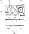
- Figure 1 schematically illustrates a tooling solution currently used in the aircraft industry, along with a top view of an example of a multispar torsion box (100).
- the tooling (101) comprises several fixed height mandrels (102) for manufacturing a single configuration of a multispar torsion box (100).
- the tooling (101) shown is used to produce a multispar torsion box (100) by a hot forming method.
- the tooling (101) comprises a base plate (103) which performs the functions of sustaining and transporting the rest of the elements which are part of the tooling (101) required for applying a thermodynamic process to the multispar torsion box (100) made of composite material, while ensuring fulfilment of the restrictive structural and dimensional tolerances.
- Different layers of composite material are provided along part of the external surface of the mandrels (102), obtaining the desired distribution of composite material which will undergo the curing process.
- the composite material is distributed following a C-shape pattern, such that the mandrels (102) can be distributed by alternating the orientation of the C-shape pattern for producing the spars (100.1) by bringing together two walls completely covered with composite material; and for producing several stringers or stiffening elements (100.2) by connecting the walls which are only partially covered with composite material.
- Figure 2 schematically illustrates the principle of the invention using a set of modular lifting surfaces as an example.
- the multispar torsion box (100) is modified only by varying the web height of the front and rear spars (101.11, 101.12) while maintaining common upper (100.3) and lower (100.4) skins. Then, the addition of different leading (106) and trailing (107) edges enables the modification of the lifting surface planform and therefore allows tailoring the size of the lifting surface to the sizing requirements of a particular member of the aircraft family.
- Figure 2 is simply a schematic representation of the concept and the implied increase in relative thickness (t/c, thickness-to-chord ratio) has not be taken into account. It is assumed that the different multispar torsion boxes (100) with different heights corresponding to each embodiment compensate the increase in loads due to the longer LE/TE chord thanks to the increased web height.
- Figure 2 does not show an increase in trailing edge chord.
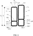
- Figure 3 shows a schematic representation of a front view of two different configurations of modular tooling (10) for manufacturing multispar torsion boxes (100) with different web heights (z1, z2) according to an embodiment of the present invention.
- the Figure to the left shows one mandrel module (11) coupled to a spacer module (12A), and the Figure to the right shows the same mandrel module (11) coupled to a bigger spacer module (12A'), thus allowing to produce a higher multispar torsion box (100) for a different structure of an aircraft (1000) of the family.
- the same modular tooling (10) allows providing different web heights to a set of multispar torsion boxes (100), thus tailoring the size of said multispar torsion boxes (100) to the sizing requirements of a particular member of an aircraft (1000) family.
- the spacer modules (12A, 12A') shown comprise a hollow beam geometry, with a first flat bottom base (12A.1, 12A.1'), substantially parallel to a second flat top base (12A.2, 12A.2'), which is spaced apart from the first flat bottom base (12A.1, 12A.1') a distance determined by two parallel walls (12A.3, 12A.4; 12A.3', 12A.4') which extend substantially perpendicularly between the first flat bottom base (12A.1, 12A.1') and the second flat top base (12A.2, 12A.2').
- the mandrel module (11) comprises a hollow beam geometry, with a first flat bottom base (11.1), substantially parallel to a second flat top base (11.2), which is spaced apart from the first flat bottom base (11.1) a distance determined by two parallel walls (11.3, 11.4) which extend substantially perpendicularly between the first flat bottom base (11.1) and the second flat top base (11.2).
- the mandrel module (11) and the spacer module (12A, 12A') are stacked, the mandrel module (11) being supported on top of each spacer module (12A, 12A'), such that the first flat bottom base (11.1) of the mandrel module (11) is supported on the second flat top base (12A.2, 12A.2') of each spacer module (12A, 12A').
- the width of the mandrel module (11), this is, the distance between the walls (11.3, 11.4) is equal to the width of each spacer modules (12A, 12A').
- the stacking (15) of the mandrel module (11) and each spacer module (12A, 12A') has a substantially rectangular geometry, comprising two closed cells.
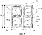
- Figure 4 shows a front view of two different configurations of modular tooling (10) for manufacturing multispar torsion boxes (100) with different web heights (z1, z2) according to an embodiment of the present invention.
- the figure to the left shows one mandrel module (11) coupled to a spacer module (12A)
- the Figure to the right shows the same mandrel module (11) coupled to the same spacer module (12A) and also coupled to an additional spacer module (12D) in the form of a plank-shaped structure, for reaching a height (z2) greater than the height (z1) reached without the plank-shaped structure (12D), thus allowing to produce a higher multispar torsion box (100) for a different structure of an aircraft (1000) of the family.
- the shared spacer module (12A) shown comprise a hollow beam geometry, with a first flat bottom base (12A.1), parallel to a second flat top base (12A.2), which is spaced apart from the first flat bottom base (12A.1) a distance determined by two parallel walls (12A.3, 12A.4) which extend perpendicularly between the first flat bottom base (12A.1) and the second flat top base (12A.2).
- the mandrel module (11) and the spacer module (12A) are stacked in the same manner than the embodiments shown in Figure 3 .
- the mandrel module (11) is supported on top of the spacer module (12A), such that the first flat bottom base (11.1) of the mandrel module (11) is supported on the second flat top base (12A.2) of the spacer module (12A).
- the width of the mandrel module (11) this is, the distance between the walls (11.3, 11.4) is equal to the width of the spacer modules (12A).
- the stacking (15) of the mandrel module (11) and the spacer module (12A) has a substantially rectangular geometry, comprising two closed cells.
- the plank-shaped structure (12D) is interposed between the mandrel module (11) and the spacer module (12A), such that the first flat bottom base (11.1) of the mandrel module (11) is supported on a top surface of the plank-shaped structure (12D), and the plank-shaped structure (12D) is supported on the second flat top base (12A.2) of the spacer module (12A).
- both configurations with and without the plank-shaped structure (12D) interposed therebetween comprise complementary fastening means for guiding the coupling process and for fixing said coupling once it has been completed.
- the mandrel module (11) and the spacer module (12A) comprise a blind hole drilled in the contact surfaces (11.1, 12A.2) of the stacking using a NC machine for achieving tight tolerances and allowing precise coordination between both holes, so that a pin (13) can penetrate both holes, substantially perpendicularly to both contact surfaces (11.1, 12.2), thus securing the coupling.
- the plank shaped structure (12D) stacked between the mandrel module (11) and the spacer module (12A) has been drilled in coordination with the holes of the contact surfaces (11.1, 12A.2) so that a longer pin (13') can pass through the whole stacking (15), thus fixing the stacking among the mandrel module (11), the plank-shaped structure (12D) and the spacer module (12A).
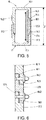
- Figure 5 shows a front view of a configuration of a mandrel module (11) coupled to a spacer module (12B) of modular tooling (10) for manufacturing multispar torsion boxes (100) according to another embodiment of the invention, wherein the mandrel module (11) is split in a first (16) and second (17) mandrel module members.
- the first mandrel module member (16) comprises a first base (16.1), a first wall (16.2) and a second wall (16.3) extending from said first base (16.1); and the second mandrel module member (17) comprises a second base (17.1), a first wall (17.2) and a second wall (17.3) extending from said second base (17.1).
- first wall (16.2) of the first mandrel module member (16) is shown abutting the first wall (17.2) of the second mandrel module member (17) along a portion of their lengths.
- Both first walls (16.2, 17.2) are configured for sliding on each other, such that, when the spacer module (12B) is replaced, or is set to couple with the mandrel module members (16, 17) in a different position, the defined web height (z) of the coupling changes thereby, said walls (16.2, 17.2) sliding on each other in order to adapt to the new configuration.
- said first walls (16.2, 17.2) are illustrated comprising a thickness reduction along the portion of their lengths configured for mechanically connecting the other respective first wall (16.2, 17.2). This way, the length of the portion in contact is maximized, such that both first walls (16.2, 17.2) can slide on each other along a plurality of configurations for defining different web heights for a multispar torsion box (100) to be manufactured.
- said first walls (16.2, 17.2) slide on each other in order to adapt to the new configuration, while remaining in mechanical contact, thus preventing the inner hollow volume from any vacuum leakage.
- the spacer module (12B) is shown interposed between the distal ends (16.4, 17.4) of the second walls (16.3, 17.3).
- the distal end (16.4, 17.4) portions of both mandrel module members (16, 17) slope obliquely towards the joint interfaces (19.1, 19.2).
- the spacer module (12B) shown has a portion substantially shaped as a trapezium, comprising two sloping surfaces configured for abutting the distal ends (16.4, 17.4) along said joint interfaces (19.1, 19.2).
- This particular configuration with oblique surfaces in mechanical contact along the joint interfaces (19.1, 19.2) provides the modular tooling (10) with continuous height adjustment as a result of the potential coupling options for the mandrel module members (16, 17) and the spacer module (12B) along the joint interfaces (19.1, 19.2).
- Figure 6 shows an alternative embodiment for replacing the oblique surfaces in mechanical contact at the joint interfaces (19.1, 19.2) shown in Figure 5 .
- the figure shows a particular embodiment of a coupling between the distal ends (16.4, 17.4) of the mandrel module members (16, 17) and the spacer module (12B) achieved by means of two rectangular projections (16.5, 17.5) which are provided only on a portion of the contact surfaces of distal ends (16.4, 17.4), since the rest of the surface is configured for matching with the spacer module (12B), which, in this particular embodiment, is in the form of a z-shaped body.
- said z-shaped body (12B) is configured for matching with the projections (16.5, 17.5) of each respective distal end (16.4, 17.4), thus being interposed between them.
- the joint interfaces (19.1, 1.2) have been provided with flat rubber sealants (18.1) which are interposed between the contact surfaces of both the rectangular projections (16.5, 17.5) and the z-shaped body (12B).
- Figure 7 shows a front view of two different configurations of modular tooling (10) for manufacturing multispar torsion boxes (100) with different web heights (z1, z2) according to an embodiment of the present invention.
- the figure to the left shows one mandrel module (11) coupled to a spacer module (12C), and the figure to the right shows the same mandrel module (11) coupled to a bigger spacer module (12C'), thus allowing to produce a higher multispar torsion box (100) for a different structure of an aircraft (1000) of the family.
- the spacer module (12C, 12C') is provided directly on the mandrel module (11) by an additive layer manufacturing process.
- the configuration corresponding to the left figure shows a mandrel module (11) made of aluminium, wherein the two opposed bases (11.1, 11.2) and the walls (11.3, 11.4) have been completely surrounded by a composite laminate which has been provided directly on the outer surface of the mandrel module (11), thus wrapping said mandrel module (11), by braiding technology.
- the length of the walls (11.3, 11.4) of the mandrel module (11), along with the thickness of the spacer module (12C) coupled thereto, resulting from the amount of composite material provided on the mandrel module (11), define a total height (z1) corresponding to the web height of a multispar torsion box (100) to be manufactured.
- Figure 8 shows modular tooling (10) comprising several configurations of a coupling between a mandrel module (11) and a spacer module (12A), arranged in combination for manufacturing a multispar torsion box (100), according to the steps of a method for manufacturing multispar torsion boxes (100) with different web heights according to the present invention.
- a distance z1 has been determined as the web height of a multispar torsion box (100) to be manufactured.
- two mandrel modules (11, 11') have been coupled to respective spacer modules (12A, 12A') tailored for achieving the web height determined (z1), according to the embodiments shown in Figure 3 .
- the mandrel modules (11, 11') and the spacer modules (12A, 12A') coupled thereto have been provided with composite material distributed according to a C-shape pattern.
- mandrel module members (16, 17; 16', 17') coupled to respective spacer modules (12B, 12B') have been arranged and coordinated among themselves by means of a longitudinal rod with rectangular shape (25), such that two stringers (23) have been defined by bringing together the walls partially covered with composite material.
- a second spar (22) has been defined by the composite material provided on one of the walls completely covered with composite material.
- composite material has been provided on both the upper and lower base of the assembled modular tooling (10) in order to define the upper skin (26) and lower skin (27) of a multispar torsion box (100).
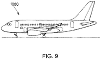
- Figure 9 shows an aircraft (1000) comprising a multispar torsion box (100) manufactured according to the invention.
Landscapes
- Engineering & Computer Science (AREA)
- Mechanical Engineering (AREA)
- Aviation & Aerospace Engineering (AREA)
- Manufacturing & Machinery (AREA)
- Architecture (AREA)
- Civil Engineering (AREA)
- Structural Engineering (AREA)
- Transportation (AREA)
- Moulding By Coating Moulds (AREA)
- Springs (AREA)
Priority Applications (4)
| Application Number | Priority Date | Filing Date | Title |
|---|---|---|---|
| ES20382047T ES2947934T3 (es) | 2020-01-27 | 2020-01-27 | Utillaje modular para caja de torsión multilarguero |
| EP20382047.7A EP3854558B1 (de) | 2020-01-27 | 2020-01-27 | Modulares werkzeug für torsionskasten mit mehreren holmen |
| US17/159,732 US11858229B2 (en) | 2020-01-27 | 2021-01-27 | Modular tooling for multi-spar torsion box |
| CN202110110427.7A CN113173255B (zh) | 2020-01-27 | 2021-01-27 | 模块化工具、组装工具组的方法以及飞行器 |
Applications Claiming Priority (1)
| Application Number | Priority Date | Filing Date | Title |
|---|---|---|---|
| EP20382047.7A EP3854558B1 (de) | 2020-01-27 | 2020-01-27 | Modulares werkzeug für torsionskasten mit mehreren holmen |
Publications (2)
| Publication Number | Publication Date |
|---|---|
| EP3854558A1 true EP3854558A1 (de) | 2021-07-28 |
| EP3854558B1 EP3854558B1 (de) | 2023-05-24 |
Family
ID=69400513
Family Applications (1)
| Application Number | Title | Priority Date | Filing Date |
|---|---|---|---|
| EP20382047.7A Active EP3854558B1 (de) | 2020-01-27 | 2020-01-27 | Modulares werkzeug für torsionskasten mit mehreren holmen |
Country Status (4)
| Country | Link |
|---|---|
| US (1) | US11858229B2 (de) |
| EP (1) | EP3854558B1 (de) |
| CN (1) | CN113173255B (de) |
| ES (1) | ES2947934T3 (de) |
Families Citing this family (1)
| Publication number | Priority date | Publication date | Assignee | Title |
|---|---|---|---|---|
| US20250264027A1 (en) * | 2024-02-15 | 2025-08-21 | Rtx Corporation | Multi-piece mandrel for building up airfoil structure |
Citations (7)
| Publication number | Priority date | Publication date | Assignee | Title |
|---|---|---|---|---|
| US5387098A (en) * | 1992-04-23 | 1995-02-07 | The Boeing Company | Flexible reusable mandrels |
| US5817269A (en) * | 1996-10-25 | 1998-10-06 | The Boeing Company | Composite fabrication method and tooling to improve part consolidation |
| EP2153979A1 (de) | 2007-04-30 | 2010-02-17 | Airbus Espana, S.L. | Aus verbundwerkstoff hergestellter torsionskasten mit mehreren holmen |
| EP2361753A1 (de) * | 2010-02-19 | 2011-08-31 | GKN Aerospace Services Limited | Verfahren und Anordnung zur Herstellung eines einstückigen Hohlprofilbauteils mit Faserverbundwerkstoff |
| EP2735502A1 (de) * | 2012-11-21 | 2014-05-28 | Airbus Operations S.L. | Optimierter Torsionkasten für ein Luftfahrzeug |
| EP3018719A2 (de) * | 2014-11-04 | 2016-05-11 | LG Electronics Inc. | Solarzelle und verfahren zur herstellung davon |
| EP3421352A1 (de) | 2017-06-28 | 2019-01-02 | Airbus Operations S.L. | Modulare auftriebsfläche und methode für deren herstellung |
Family Cites Families (7)
| Publication number | Priority date | Publication date | Assignee | Title |
|---|---|---|---|---|
| US6513757B1 (en) * | 1999-07-19 | 2003-02-04 | Fuji Jukogyo Kabushiki Kaisha | Wing of composite material and method of fabricating the same |
| ITTO20100175A1 (it) * | 2010-03-08 | 2011-09-09 | Alenia Aeronautica Spa | Procedimento per la fabbricazione di longheroni alari e travi di fusoliera a doppio t in materiale composito a sezione variabile |
| EP2851283B1 (de) * | 2013-09-23 | 2018-03-28 | Airbus Operations S.L. | Verfahren zur herstellung eines aeronautischen torsionskastens, torsionskasten und werkzeug zur herstellung eines aeronautischen torsionskastens |
| EP2889214B1 (de) * | 2013-12-31 | 2020-02-05 | Airbus Operations, S.L. | Hochintegriertes eingegossenes Gehäuse aus Verbundwerkstoff und Verfahren zur Herstellung |
| US20170259521A1 (en) * | 2016-02-08 | 2017-09-14 | Bell Helicopter Textron Inc. | Large Cell Core Stiffened Panels with Solid Inserts |
| GB201709891D0 (en) * | 2017-06-21 | 2017-08-02 | Elson Space Eng Ese Ltd | Aerial vehicle |
| GB201710385D0 (en) * | 2017-06-29 | 2017-08-16 | Airbus Operations Gmbh | Aerofoil structure and method of assembly |
-
2020
- 2020-01-27 ES ES20382047T patent/ES2947934T3/es active Active
- 2020-01-27 EP EP20382047.7A patent/EP3854558B1/de active Active
-
2021
- 2021-01-27 US US17/159,732 patent/US11858229B2/en active Active
- 2021-01-27 CN CN202110110427.7A patent/CN113173255B/zh active Active
Patent Citations (7)
| Publication number | Priority date | Publication date | Assignee | Title |
|---|---|---|---|---|
| US5387098A (en) * | 1992-04-23 | 1995-02-07 | The Boeing Company | Flexible reusable mandrels |
| US5817269A (en) * | 1996-10-25 | 1998-10-06 | The Boeing Company | Composite fabrication method and tooling to improve part consolidation |
| EP2153979A1 (de) | 2007-04-30 | 2010-02-17 | Airbus Espana, S.L. | Aus verbundwerkstoff hergestellter torsionskasten mit mehreren holmen |
| EP2361753A1 (de) * | 2010-02-19 | 2011-08-31 | GKN Aerospace Services Limited | Verfahren und Anordnung zur Herstellung eines einstückigen Hohlprofilbauteils mit Faserverbundwerkstoff |
| EP2735502A1 (de) * | 2012-11-21 | 2014-05-28 | Airbus Operations S.L. | Optimierter Torsionkasten für ein Luftfahrzeug |
| EP3018719A2 (de) * | 2014-11-04 | 2016-05-11 | LG Electronics Inc. | Solarzelle und verfahren zur herstellung davon |
| EP3421352A1 (de) | 2017-06-28 | 2019-01-02 | Airbus Operations S.L. | Modulare auftriebsfläche und methode für deren herstellung |
Also Published As
| Publication number | Publication date |
|---|---|
| US11858229B2 (en) | 2024-01-02 |
| US20210229387A1 (en) | 2021-07-29 |
| CN113173255B (zh) | 2026-01-02 |
| EP3854558B1 (de) | 2023-05-24 |
| CN113173255A (zh) | 2021-07-27 |
| ES2947934T3 (es) | 2023-08-24 |
Similar Documents
| Publication | Publication Date | Title |
|---|---|---|
| EP2735502B1 (de) | Optimierter Torsionskasten für ein Luftfahrzeug | |
| EP2735504B1 (de) | Herstellungsmethode für eine hochintegrierte struktur mit leit- und hinterkantenrippen für eine flugzeugtragfläche | |
| EP2153979B1 (de) | Aus verbundwerkstoff hergestellter torsionskasten mit mehreren holmen | |
| EP2301840B1 (de) | Integrierte luftfahrzeugsturktur aus verbundwerkstoff | |
| EP3372395B1 (de) | Effiziente substrukturen | |
| EP3301014B1 (de) | Tragflächenförmiger körper mit hülle auf verbundstoffbasis mit integriertem hutförmigen holm | |
| US6237873B1 (en) | Composite material wing structure | |
| EP2851283B1 (de) | Verfahren zur herstellung eines aeronautischen torsionskastens, torsionskasten und werkzeug zur herstellung eines aeronautischen torsionskastens | |
| US20150183506A1 (en) | Highly integrated infused box made of composite material and method of manufacturing | |
| EP2343237B1 (de) | Flugzeugrumpfrahmen aus Verbundstoffmaterial mit stabilisiertem Steg | |
| EP2589532A2 (de) | Aus einem verbundmaterial hergestellter flugzeugrumpf und herstellungsverfahren dafür | |
| WO2009064581A1 (en) | Method and tools for fabricating composite beams | |
| US9701393B2 (en) | Highly integrated inner structure of a torsion box of an aircraft lifting surface | |
| EP2876044B1 (de) | Passagiertür-Eckenkomponente und Herstellungsverfahren für Passagiertür-Eckenkomponente eines Flugzeugs oder Raumfahrzeugs | |
| EP3501971A1 (de) | Flugzeugheckrumpfabschnitt und herstellungsverfahren dafür | |
| US9387922B2 (en) | Main supporting structure of an aircraft lifting surface | |
| US11858229B2 (en) | Modular tooling for multi-spar torsion box | |
| EP3590824B1 (de) | Verfahren zur herstellung der hinterkantenrippen und der auflagerippen von hinterkanten von flugzeughubflächen | |
| Nelson et al. | Conceptual Design Studies of Composite AMST | |
| CA3205495A1 (en) | Composite multi-spar aircraft lifting surface |
Legal Events
| Date | Code | Title | Description |
|---|---|---|---|
| PUAI | Public reference made under article 153(3) epc to a published international application that has entered the european phase |
Free format text: ORIGINAL CODE: 0009012 |
|
| STAA | Information on the status of an ep patent application or granted ep patent |
Free format text: STATUS: THE APPLICATION HAS BEEN PUBLISHED |
|
| AK | Designated contracting states |
Kind code of ref document: A1 Designated state(s): AL AT BE BG CH CY CZ DE DK EE ES FI FR GB GR HR HU IE IS IT LI LT LU LV MC MK MT NL NO PL PT RO RS SE SI SK SM TR |
|
| STAA | Information on the status of an ep patent application or granted ep patent |
Free format text: STATUS: REQUEST FOR EXAMINATION WAS MADE |
|
| 17P | Request for examination filed |
Effective date: 20220128 |
|
| RBV | Designated contracting states (corrected) |
Designated state(s): AL AT BE BG CH CY CZ DE DK EE ES FI FR GB GR HR HU IE IS IT LI LT LU LV MC MK MT NL NO PL PT RO RS SE SI SK SM TR |
|
| GRAP | Despatch of communication of intention to grant a patent |
Free format text: ORIGINAL CODE: EPIDOSNIGR1 |
|
| STAA | Information on the status of an ep patent application or granted ep patent |
Free format text: STATUS: GRANT OF PATENT IS INTENDED |
|
| RIC1 | Information provided on ipc code assigned before grant |
Ipc: B64C 3/20 20060101ALI20221212BHEP Ipc: B64C 3/18 20060101ALI20221212BHEP Ipc: B29C 33/48 20060101ALI20221212BHEP Ipc: B29C 33/30 20060101AFI20221212BHEP |
|
| INTG | Intention to grant announced |
Effective date: 20230104 |
|
| GRAS | Grant fee paid |
Free format text: ORIGINAL CODE: EPIDOSNIGR3 |
|
| GRAA | (expected) grant |
Free format text: ORIGINAL CODE: 0009210 |
|
| STAA | Information on the status of an ep patent application or granted ep patent |
Free format text: STATUS: THE PATENT HAS BEEN GRANTED |
|
| AK | Designated contracting states |
Kind code of ref document: B1 Designated state(s): AL AT BE BG CH CY CZ DE DK EE ES FI FR GB GR HR HU IE IS IT LI LT LU LV MC MK MT NL NO PL PT RO RS SE SI SK SM TR |
|
| REG | Reference to a national code |
Ref country code: GB Ref legal event code: FG4D |
|
| REG | Reference to a national code |
Ref country code: CH Ref legal event code: EP |
|
| REG | Reference to a national code |
Ref country code: DE Ref legal event code: R096 Ref document number: 602020011091 Country of ref document: DE |
|
| REG | Reference to a national code |
Ref country code: AT Ref legal event code: REF Ref document number: 1569257 Country of ref document: AT Kind code of ref document: T Effective date: 20230615 |
|
| REG | Reference to a national code |
Ref country code: IE Ref legal event code: FG4D |
|
| REG | Reference to a national code |
Ref country code: ES Ref legal event code: FG2A Ref document number: 2947934 Country of ref document: ES Kind code of ref document: T3 Effective date: 20230824 |
|
| REG | Reference to a national code |
Ref country code: LT Ref legal event code: MG9D |
|
| REG | Reference to a national code |
Ref country code: NL Ref legal event code: MP Effective date: 20230524 |
|
| REG | Reference to a national code |
Ref country code: AT Ref legal event code: MK05 Ref document number: 1569257 Country of ref document: AT Kind code of ref document: T Effective date: 20230524 |
|
| PG25 | Lapsed in a contracting state [announced via postgrant information from national office to epo] |
Ref country code: SE Free format text: LAPSE BECAUSE OF FAILURE TO SUBMIT A TRANSLATION OF THE DESCRIPTION OR TO PAY THE FEE WITHIN THE PRESCRIBED TIME-LIMIT Effective date: 20230524 Ref country code: PT Free format text: LAPSE BECAUSE OF FAILURE TO SUBMIT A TRANSLATION OF THE DESCRIPTION OR TO PAY THE FEE WITHIN THE PRESCRIBED TIME-LIMIT Effective date: 20230925 Ref country code: NO Free format text: LAPSE BECAUSE OF FAILURE TO SUBMIT A TRANSLATION OF THE DESCRIPTION OR TO PAY THE FEE WITHIN THE PRESCRIBED TIME-LIMIT Effective date: 20230824 Ref country code: NL Free format text: LAPSE BECAUSE OF FAILURE TO SUBMIT A TRANSLATION OF THE DESCRIPTION OR TO PAY THE FEE WITHIN THE PRESCRIBED TIME-LIMIT Effective date: 20230524 Ref country code: AT Free format text: LAPSE BECAUSE OF FAILURE TO SUBMIT A TRANSLATION OF THE DESCRIPTION OR TO PAY THE FEE WITHIN THE PRESCRIBED TIME-LIMIT Effective date: 20230524 |
|
| PG25 | Lapsed in a contracting state [announced via postgrant information from national office to epo] |
Ref country code: RS Free format text: LAPSE BECAUSE OF FAILURE TO SUBMIT A TRANSLATION OF THE DESCRIPTION OR TO PAY THE FEE WITHIN THE PRESCRIBED TIME-LIMIT Effective date: 20230524 Ref country code: PL Free format text: LAPSE BECAUSE OF FAILURE TO SUBMIT A TRANSLATION OF THE DESCRIPTION OR TO PAY THE FEE WITHIN THE PRESCRIBED TIME-LIMIT Effective date: 20230524 Ref country code: LV Free format text: LAPSE BECAUSE OF FAILURE TO SUBMIT A TRANSLATION OF THE DESCRIPTION OR TO PAY THE FEE WITHIN THE PRESCRIBED TIME-LIMIT Effective date: 20230524 Ref country code: LT Free format text: LAPSE BECAUSE OF FAILURE TO SUBMIT A TRANSLATION OF THE DESCRIPTION OR TO PAY THE FEE WITHIN THE PRESCRIBED TIME-LIMIT Effective date: 20230524 Ref country code: IS Free format text: LAPSE BECAUSE OF FAILURE TO SUBMIT A TRANSLATION OF THE DESCRIPTION OR TO PAY THE FEE WITHIN THE PRESCRIBED TIME-LIMIT Effective date: 20230924 Ref country code: HR Free format text: LAPSE BECAUSE OF FAILURE TO SUBMIT A TRANSLATION OF THE DESCRIPTION OR TO PAY THE FEE WITHIN THE PRESCRIBED TIME-LIMIT Effective date: 20230524 Ref country code: GR Free format text: LAPSE BECAUSE OF FAILURE TO SUBMIT A TRANSLATION OF THE DESCRIPTION OR TO PAY THE FEE WITHIN THE PRESCRIBED TIME-LIMIT Effective date: 20230825 |
|
| PG25 | Lapsed in a contracting state [announced via postgrant information from national office to epo] |
Ref country code: FI Free format text: LAPSE BECAUSE OF FAILURE TO SUBMIT A TRANSLATION OF THE DESCRIPTION OR TO PAY THE FEE WITHIN THE PRESCRIBED TIME-LIMIT Effective date: 20230524 |
|
| PG25 | Lapsed in a contracting state [announced via postgrant information from national office to epo] |
Ref country code: SK Free format text: LAPSE BECAUSE OF FAILURE TO SUBMIT A TRANSLATION OF THE DESCRIPTION OR TO PAY THE FEE WITHIN THE PRESCRIBED TIME-LIMIT Effective date: 20230524 |
|
| PG25 | Lapsed in a contracting state [announced via postgrant information from national office to epo] |
Ref country code: SM Free format text: LAPSE BECAUSE OF FAILURE TO SUBMIT A TRANSLATION OF THE DESCRIPTION OR TO PAY THE FEE WITHIN THE PRESCRIBED TIME-LIMIT Effective date: 20230524 Ref country code: SK Free format text: LAPSE BECAUSE OF FAILURE TO SUBMIT A TRANSLATION OF THE DESCRIPTION OR TO PAY THE FEE WITHIN THE PRESCRIBED TIME-LIMIT Effective date: 20230524 Ref country code: RO Free format text: LAPSE BECAUSE OF FAILURE TO SUBMIT A TRANSLATION OF THE DESCRIPTION OR TO PAY THE FEE WITHIN THE PRESCRIBED TIME-LIMIT Effective date: 20230524 Ref country code: EE Free format text: LAPSE BECAUSE OF FAILURE TO SUBMIT A TRANSLATION OF THE DESCRIPTION OR TO PAY THE FEE WITHIN THE PRESCRIBED TIME-LIMIT Effective date: 20230524 Ref country code: DK Free format text: LAPSE BECAUSE OF FAILURE TO SUBMIT A TRANSLATION OF THE DESCRIPTION OR TO PAY THE FEE WITHIN THE PRESCRIBED TIME-LIMIT Effective date: 20230524 Ref country code: CZ Free format text: LAPSE BECAUSE OF FAILURE TO SUBMIT A TRANSLATION OF THE DESCRIPTION OR TO PAY THE FEE WITHIN THE PRESCRIBED TIME-LIMIT Effective date: 20230524 |
|
| REG | Reference to a national code |
Ref country code: DE Ref legal event code: R097 Ref document number: 602020011091 Country of ref document: DE |
|
| PLBE | No opposition filed within time limit |
Free format text: ORIGINAL CODE: 0009261 |
|
| STAA | Information on the status of an ep patent application or granted ep patent |
Free format text: STATUS: NO OPPOSITION FILED WITHIN TIME LIMIT |
|
| 26N | No opposition filed |
Effective date: 20240227 |
|
| PG25 | Lapsed in a contracting state [announced via postgrant information from national office to epo] |
Ref country code: SI Free format text: LAPSE BECAUSE OF FAILURE TO SUBMIT A TRANSLATION OF THE DESCRIPTION OR TO PAY THE FEE WITHIN THE PRESCRIBED TIME-LIMIT Effective date: 20230524 |
|
| PG25 | Lapsed in a contracting state [announced via postgrant information from national office to epo] |
Ref country code: SI Free format text: LAPSE BECAUSE OF FAILURE TO SUBMIT A TRANSLATION OF THE DESCRIPTION OR TO PAY THE FEE WITHIN THE PRESCRIBED TIME-LIMIT Effective date: 20230524 |
|
| PG25 | Lapsed in a contracting state [announced via postgrant information from national office to epo] |
Ref country code: MC Free format text: LAPSE BECAUSE OF FAILURE TO SUBMIT A TRANSLATION OF THE DESCRIPTION OR TO PAY THE FEE WITHIN THE PRESCRIBED TIME-LIMIT Effective date: 20230524 |
|
| PG25 | Lapsed in a contracting state [announced via postgrant information from national office to epo] |
Ref country code: MC Free format text: LAPSE BECAUSE OF FAILURE TO SUBMIT A TRANSLATION OF THE DESCRIPTION OR TO PAY THE FEE WITHIN THE PRESCRIBED TIME-LIMIT Effective date: 20230524 |
|
| REG | Reference to a national code |
Ref country code: CH Ref legal event code: PL |
|
| PG25 | Lapsed in a contracting state [announced via postgrant information from national office to epo] |
Ref country code: LU Free format text: LAPSE BECAUSE OF NON-PAYMENT OF DUE FEES Effective date: 20240127 |
|
| PG25 | Lapsed in a contracting state [announced via postgrant information from national office to epo] |
Ref country code: LU Free format text: LAPSE BECAUSE OF NON-PAYMENT OF DUE FEES Effective date: 20240127 |
|
| PG25 | Lapsed in a contracting state [announced via postgrant information from national office to epo] |
Ref country code: BE Free format text: LAPSE BECAUSE OF NON-PAYMENT OF DUE FEES Effective date: 20240131 |
|
| PG25 | Lapsed in a contracting state [announced via postgrant information from national office to epo] |
Ref country code: CH Free format text: LAPSE BECAUSE OF NON-PAYMENT OF DUE FEES Effective date: 20240131 |
|
| PG25 | Lapsed in a contracting state [announced via postgrant information from national office to epo] |
Ref country code: CH Free format text: LAPSE BECAUSE OF NON-PAYMENT OF DUE FEES Effective date: 20240131 Ref country code: BE Free format text: LAPSE BECAUSE OF NON-PAYMENT OF DUE FEES Effective date: 20240131 |
|
| REG | Reference to a national code |
Ref country code: BE Ref legal event code: MM Effective date: 20240131 |
|
| PG25 | Lapsed in a contracting state [announced via postgrant information from national office to epo] |
Ref country code: BG Free format text: LAPSE BECAUSE OF FAILURE TO SUBMIT A TRANSLATION OF THE DESCRIPTION OR TO PAY THE FEE WITHIN THE PRESCRIBED TIME-LIMIT Effective date: 20230524 |
|
| PG25 | Lapsed in a contracting state [announced via postgrant information from national office to epo] |
Ref country code: BG Free format text: LAPSE BECAUSE OF FAILURE TO SUBMIT A TRANSLATION OF THE DESCRIPTION OR TO PAY THE FEE WITHIN THE PRESCRIBED TIME-LIMIT Effective date: 20230524 |
|
| PG25 | Lapsed in a contracting state [announced via postgrant information from national office to epo] |
Ref country code: IE Free format text: LAPSE BECAUSE OF NON-PAYMENT OF DUE FEES Effective date: 20240127 |
|
| PG25 | Lapsed in a contracting state [announced via postgrant information from national office to epo] |
Ref country code: IE Free format text: LAPSE BECAUSE OF NON-PAYMENT OF DUE FEES Effective date: 20240127 |
|
| PG25 | Lapsed in a contracting state [announced via postgrant information from national office to epo] |
Ref country code: CY Free format text: LAPSE BECAUSE OF FAILURE TO SUBMIT A TRANSLATION OF THE DESCRIPTION OR TO PAY THE FEE WITHIN THE PRESCRIBED TIME-LIMIT; INVALID AB INITIO Effective date: 20200127 |
|
| PG25 | Lapsed in a contracting state [announced via postgrant information from national office to epo] |
Ref country code: HU Free format text: LAPSE BECAUSE OF FAILURE TO SUBMIT A TRANSLATION OF THE DESCRIPTION OR TO PAY THE FEE WITHIN THE PRESCRIBED TIME-LIMIT; INVALID AB INITIO Effective date: 20200127 |
|
| PG25 | Lapsed in a contracting state [announced via postgrant information from national office to epo] |
Ref country code: TR Free format text: LAPSE BECAUSE OF FAILURE TO SUBMIT A TRANSLATION OF THE DESCRIPTION OR TO PAY THE FEE WITHIN THE PRESCRIBED TIME-LIMIT Effective date: 20230524 |
|
| PGFP | Annual fee paid to national office [announced via postgrant information from national office to epo] |
Ref country code: GB Payment date: 20260123 Year of fee payment: 7 |
|
| PGFP | Annual fee paid to national office [announced via postgrant information from national office to epo] |
Ref country code: ES Payment date: 20260227 Year of fee payment: 7 |
|
| PGFP | Annual fee paid to national office [announced via postgrant information from national office to epo] |
Ref country code: DE Payment date: 20260121 Year of fee payment: 7 |
|
| PGFP | Annual fee paid to national office [announced via postgrant information from national office to epo] |
Ref country code: IT Payment date: 20260126 Year of fee payment: 7 |
|
| PGFP | Annual fee paid to national office [announced via postgrant information from national office to epo] |
Ref country code: FR Payment date: 20260123 Year of fee payment: 7 |