EP3854567B1 - Outil et procédé de fabrication d'un récipient - Google Patents
Outil et procédé de fabrication d'un récipient Download PDFInfo
- Publication number
- EP3854567B1 EP3854567B1 EP21163359.9A EP21163359A EP3854567B1 EP 3854567 B1 EP3854567 B1 EP 3854567B1 EP 21163359 A EP21163359 A EP 21163359A EP 3854567 B1 EP3854567 B1 EP 3854567B1
- Authority
- EP
- European Patent Office
- Prior art keywords
- wall
- container
- section
- base
- moulding
- Prior art date
- Legal status (The legal status is an assumption and is not a legal conclusion. Google has not performed a legal analysis and makes no representation as to the accuracy of the status listed.)
- Active
Links
Images





Classifications
-
- B—PERFORMING OPERATIONS; TRANSPORTING
- B65—CONVEYING; PACKING; STORING; HANDLING THIN OR FILAMENTARY MATERIAL
- B65D—CONTAINERS FOR STORAGE OR TRANSPORT OF ARTICLES OR MATERIALS, e.g. BAGS, BARRELS, BOTTLES, BOXES, CANS, CARTONS, CRATES, DRUMS, JARS, TANKS, HOPPERS, FORWARDING CONTAINERS; ACCESSORIES, CLOSURES, OR FITTINGS THEREFOR; PACKAGING ELEMENTS; PACKAGES
- B65D1/00—Rigid or semi-rigid containers having bodies formed in one piece, e.g. by casting metallic material, by moulding plastics, by blowing vitreous material, by throwing ceramic material, by moulding pulped fibrous material or by deep-drawing operations performed on sheet material
- B65D1/22—Boxes or like containers with side walls of substantial depth for enclosing contents
- B65D1/26—Thin-walled containers, e.g. formed by deep-drawing operations
-
- B—PERFORMING OPERATIONS; TRANSPORTING
- B29—WORKING OF PLASTICS; WORKING OF SUBSTANCES IN A PLASTIC STATE IN GENERAL
- B29C—SHAPING OR JOINING OF PLASTICS; SHAPING OF MATERIAL IN A PLASTIC STATE, NOT OTHERWISE PROVIDED FOR; AFTER-TREATMENT OF THE SHAPED PRODUCTS, e.g. REPAIRING
- B29C51/00—Shaping by thermoforming, i.e. shaping sheets or sheet like preforms after heating, e.g. shaping sheets in matched moulds or by deep-drawing; Apparatus therefor
- B29C51/26—Component parts, details or accessories; Auxiliary operations
- B29C51/30—Moulds
- B29C51/34—Moulds for undercut articles
- B29C51/346—Moulds for undercut articles specially adapted to facilitate the destacking of nestable containers
-
- B—PERFORMING OPERATIONS; TRANSPORTING
- B29—WORKING OF PLASTICS; WORKING OF SUBSTANCES IN A PLASTIC STATE IN GENERAL
- B29C—SHAPING OR JOINING OF PLASTICS; SHAPING OF MATERIAL IN A PLASTIC STATE, NOT OTHERWISE PROVIDED FOR; AFTER-TREATMENT OF THE SHAPED PRODUCTS, e.g. REPAIRING
- B29C51/00—Shaping by thermoforming, i.e. shaping sheets or sheet like preforms after heating, e.g. shaping sheets in matched moulds or by deep-drawing; Apparatus therefor
- B29C51/26—Component parts, details or accessories; Auxiliary operations
- B29C51/30—Moulds
-
- B—PERFORMING OPERATIONS; TRANSPORTING
- B65—CONVEYING; PACKING; STORING; HANDLING THIN OR FILAMENTARY MATERIAL
- B65D—CONTAINERS FOR STORAGE OR TRANSPORT OF ARTICLES OR MATERIALS, e.g. BAGS, BARRELS, BOTTLES, BOXES, CANS, CARTONS, CRATES, DRUMS, JARS, TANKS, HOPPERS, FORWARDING CONTAINERS; ACCESSORIES, CLOSURES, OR FITTINGS THEREFOR; PACKAGING ELEMENTS; PACKAGES
- B65D21/00—Nestable, stackable or joinable containers; Containers of variable capacity
- B65D21/02—Containers specially shaped, or provided with fittings or attachments, to facilitate nesting, stacking, or joining together
- B65D21/0209—Containers specially shaped, or provided with fittings or attachments, to facilitate nesting, stacking, or joining together stackable or joined together one-upon-the-other in the upright or upside-down position
- B65D21/0213—Containers presenting a continuous stacking profile along the upper or lower edge of at least two opposite side walls
-
- B—PERFORMING OPERATIONS; TRANSPORTING
- B29—WORKING OF PLASTICS; WORKING OF SUBSTANCES IN A PLASTIC STATE IN GENERAL
- B29C—SHAPING OR JOINING OF PLASTICS; SHAPING OF MATERIAL IN A PLASTIC STATE, NOT OTHERWISE PROVIDED FOR; AFTER-TREATMENT OF THE SHAPED PRODUCTS, e.g. REPAIRING
- B29C51/00—Shaping by thermoforming, i.e. shaping sheets or sheet like preforms after heating, e.g. shaping sheets in matched moulds or by deep-drawing; Apparatus therefor
- B29C51/08—Deep drawing or matched-mould forming, i.e. using mechanical means only
-
- B—PERFORMING OPERATIONS; TRANSPORTING
- B29—WORKING OF PLASTICS; WORKING OF SUBSTANCES IN A PLASTIC STATE IN GENERAL
- B29L—INDEXING SCHEME ASSOCIATED WITH SUBCLASS B29C, RELATING TO PARTICULAR ARTICLES
- B29L2031/00—Other particular articles
- B29L2031/712—Containers; Packaging elements or accessories, Packages
- B29L2031/7134—Crates, e.g. for bottles
-
- B—PERFORMING OPERATIONS; TRANSPORTING
- B29—WORKING OF PLASTICS; WORKING OF SUBSTANCES IN A PLASTIC STATE IN GENERAL
- B29L—INDEXING SCHEME ASSOCIATED WITH SUBCLASS B29C, RELATING TO PARTICULAR ARTICLES
- B29L2031/00—Other particular articles
- B29L2031/712—Containers; Packaging elements or accessories, Packages
- B29L2031/7162—Boxes, cartons, cases
Definitions
- the invention relates to a tool for producing a container.
- the invention further relates to a method for producing a container.
- From the DE 199 64 255 C2 is a transport container made of plastic with a base and a continuous side wall made of the same material as the base, as well as flanges that protrude beyond an outer contour of the side wall around the entire outside of the container.
- the flanges form an angle of less than 90° with the side wall on their underside and are designed as a groove that is open towards the inside.
- the DE 199 27 069 C2 a transport container made of plastic and designed as a deep-drawn plastic part with a base and a circumferential side wall made of the same material as the base.
- the transport container comprises a flange designed as a hollow profile that protrudes over an outer contour of the side wall and around the entire outside of the container.
- the flange is designed as an open groove towards the inside of the container and is arranged at a distance from the base.
- a side wall adjoining the flange at the bottom is set back by at least one wall thickness of the side wall and the flange encloses an angle of less than 90° with the side wall on its underside.
- a simple circumferential flange is provided on the upper edge area of the side wall, which encloses an angle of less than 90° with the outer wall on its underside.
- the DE 38 14 999 A1 describes a device for deep drawing stackable pallets, which have a base and at an angle to the vertical have inclined walls. The walls end at their upper edge in a step that serves as a support for the base of another pallet above it.
- the device comprises a tool whose surface has a shape that complements the inside of the pallet.
- the device also has means for pulling a softened plastic plate over and holding it down on the tool.
- the tool is provided on its upper edges with ledge-like protruding strips for forming undercut beads on the edge of the base.
- the strips can be pivoted about axes parallel to their longitudinal extension in such a way that the strips are pivoted when the pallets are being formed and slide out of the undercuts.
- the invention is based on the object of specifying a novel tool for producing a container and a novel method for producing a container.
- the tool according to the invention for producing a container from plastic in a thermoforming process comprises a positive mold.
- the positive mold comprises a base section for forming a container base, a side wall section for forming a circumferential side wall formed of the same material as the base, and a wall for forming a circumferentially projecting part that protrudes over an outer contour of the side wall of the container around the entire outside of the container and is designed as Hollow profile stacking edge, which is designed as an open groove inwards towards the inside of the container and is arranged at a distance from the base.
- the wall In a molding position for molding the container, the wall is arranged to protrude all the way around the outside of the positive mold, with an angle of less than 90° being formed between a wall side directed towards the base section and a region of the associated side wall section extending from this wall side in the direction of the base section.
- the wall which is designed, for example, as a circumferential wall region, can be moved from the molding position into a demolding position, with a distance of an end of the wall protruding in the molding position from the side wall section being reduced in the demolding position.
- a container in particular a transport container, can be produced in a thermoforming process, in particular a plastic deep-drawing process, which comprises at least one stacking edge designed as an inwardly open groove.
- a thermoforming process in particular a plastic deep-drawing process, which comprises at least one stacking edge designed as an inwardly open groove.
- the wall comprises several wall segments, each of which is arranged pivotably on the side wall section.
- movement of the wall segments in the molding direction, which runs from the base section along the side wall section is blocked.
- movement in the demolding direction, which runs opposite to the molding direction is permitted.
- thermoforming can be carried out while ensuring a target position of the wall and, on the other hand, when the container moves in the demolding direction, ie during a backward movement, the wall segments are pivoted in such a way that they release the stacking edge, ie the inward-facing groove.
- the pivotable wall segments are each coupled to at least one spring, which exerts a force on the wall segments in the opposite direction of pivoting.
- the spring force generated enables the mold position of the wall to be secured in a particularly reliable and simple manner during the molding of the container and a reliable and automatic return of the wall to this mold position after the container has been removed from the mold.
- the wall comprises several wall segments designed as sliders, which can be moved from the mold position into the interior of the positive mold. Wall segments that can be moved in this way enable the stack edge, i.e. the inward-facing groove, to be completely released when the container is removed from the mold, whereby no deformation of the stack edge is required for demolding.
- wall segments arranged at corners of the side wall section are designed as gravity slides or gravity slide systems, which are locked in the molding position by the side wall section and adjacent slides and are released after adjacent slides are moved into the interior of the positive mold in such a way that they move automatically into the interior of the positive mold, for example into a starting position, due to the force of weight during, or after demolding.
- This embodiment enables particularly reliable production of the container with the stacking edge due to particularly reliable and secure positioning of the wall segments during molding and reliable and technically easy-to-implement release of the stacking edge, i.e. the inward-facing groove, when the container is demolded.
- the slides are each equipped with a motor, hydraulic and/or pneumatic drive to carry out the movement. This allows the slider to be moved quickly and conveniently with a defined movement sequence.
- a blank made of thermoplastic is heated in a thermoforming process, in particular a plastic deep-drawing process.
- the blank is then formed using the positive mold, whereby a container base is formed from the blank on the base section of the positive mold, a circumferential side wall formed from the same material as the base is formed on a side wall section, and a stacking edge formed as a hollow profile that protrudes over an outer contour of the side wall of the container around an entire outside of the container, which stacking edge is formed as an open groove inwards towards an inside of the container and is arranged at a distance from the base, is formed on a wall arranged on the side wall section.
- the wall is arranged in a molding position so as to protrude circumferentially around an entire outside of the positive mold in such a way that an angle of less than 90° is formed between a wall side directed towards the base section and a region of the associated side wall section extending from this wall side in the direction of the base section. Furthermore, after the blank has been formed, the wall is moved into a demolding position in which a distance of an end of the wall protruding in the molding position from the side wall section is reduced.
- a container in particular a transport container, can be produced in a thermoforming process, in particular a plastic deep-drawing process, which comprises at least one stacking edge designed as an inwardly open groove.
- a thermoforming process in particular a plastic deep-drawing process, which comprises at least one stacking edge designed as an inwardly open groove.
- the movement of the wall into the demolding position is guided by the container when the container is demolded from the positive mold. This ensures that the same relative position of the wall segments to the container can always be ensured at a defined position of the container during demolding and thus a consistent result and, as a result, consistent quality can always be achieved.
- the container is cooled before demolding to a temperature which allows elastic deformation of the container at least in the area of the stacking edge. This avoids plastic deformation of the stacking edge when the container is demolded and the resulting damage to the container.
- the movement of the wall into the demolding position is carried out by means of at least one motor, hydraulic and/or pneumatic drive. This enables the slides to be moved quickly and conveniently with a defined movement sequence.
- Figure 1 a sectional view of a possible embodiment of a container 1 is shown.
- Figure 2 shows an enlarged section of the sectional view according to Figure 1 .
- the container 1 is designed, for example, as a transport or packaging container and comprises a container base 2, the properties of which are adapted to the goods to be transported.
- the container base 2 is profiled in such a way that it comprises so-called nests, which enable the goods to be inserted to be transported in a non-slip and damage-free manner.
- the container base 2 can also have other properties, for example be flat.
- a side wall 3 of the same material is connected to the container base 2 and ends in the upper area in a flange 7 in the illustrated embodiment of the container 1, which is made of the same material all the way around the entire container 1 and protrudes over an outer side of the side wall 3.
- the flange 7 forms a stacking edge 8.
- a further outwardly projecting flange 4 is formed, which is designed as an inwardly open groove and thus has an upper side 6 and a lower side 5.
- a section 3a of the side wall 3, which projects downwards from the flange 4 in this area, is set back from the rest of the side wall 3 by a dimension which corresponds to at least one material thickness of the side wall 3, but is somewhat larger in one possible embodiment, so that a problem-free jam-free stacking of several containers 1 on top of one another and in sections inside one another is possible.
- the flange 4 is inclined on its underside 5 relative to the adjoining section 3a of the side wall 3 and forms an angle ⁇ with the section 3a of the side wall 3 which is less than 90°.
- the flange 7 also encloses an angle that is less than 90°, so that when several containers 1 are stacked, the top of the flange 7 lies under the bottom 5 of the flange 4, thereby achieving a dust- and splash-proof connection of the individual containers 1 when stacked.
- the flange 4 thus also forms a stacking edge 9.
- Figure 3 is a perspective view of a possible embodiment of a tool 10 for producing a Figures 1 and 2 shown container 1.
- the container 1 is manufactured by means of the tool 10 in a thermoforming process from a blank made of plastic, in particular in a plastic deep-drawing process.
- the tool 10 comprises a positive mold 11 with a bottom section 12 for forming the container bottom 2.
- the positive mold 11 further comprises a side wall section 13 for forming the circumferential side wall 3 which is made of the same material as the container base 2.
- the positive mold 11 comprises a wall 14 for forming the stacking edge 9, which projects beyond the outer contour of the side wall 3 of the container 1 around the entire outside of the container and is designed as a hollow profile, which is designed as an open groove towards the inside of the container and is arranged at a distance from the container bottom 2.
- the positive mold 11 comprises a base plate 15, from which the side wall section 13 projects at least substantially vertically upwards.
- a circumferential recess 16 is arranged to form the upper stacking edge 8 of the container 1.
- the blank (not shown in detail) made of plastic, in particular thermoplastic, is first heated in such a way that it is deformable.
- the heating takes place, for example, by means of external heat sources (not shown in detail).
- the blank is then formed using negative pressure and/or a stamp (not shown) in such a way that the plastic is pulled over the positive mold 11 and its outer contour forms an inner contour of the container 1 produced.
- the lower flange 4 i.e. its groove directed inwards and thus towards the positive mold 11, is formed by means of the protruding wall 14.
- the wall 14 is arranged in a molding position for forming the container 1 so as to protrude all the way around the outside of the positive mold 11.
- the angle ⁇ which is smaller than 90°, is formed between a wall side 17 directed towards the base section 12, on which the underside 5 of the stacking edge 9 is formed, and a region 13a of the associated side wall section 13 extending from this wall side 17 in the direction of the base section 12. This is shown in Figure 4 shown in more detail.
- the wall 14 is designed to be movable and is moved during demolding from the molding position into at least one demolding position in which a distance d of an end of the wall 14 protruding in the molding position from the side wall section 13 is reduced in order to release the peripheral stacking edge 9 during demolding of the container 1.
- the wall 14 comprises several wall segments 14.1 to 14.n, in the embodiment shown eight wall segments 14.1 to 14.n, which are each arranged pivotably or foldably on the side wall section 13.
- a number of pivotable wall segments 14.1 to 14.n for forming of the stacking edge 9 depends on the outer contour of the container 1 to be produced.
- a movement of the wall segments 14.1 to 14.n is blocked in the molding position in the molding direction Y, which runs from the base section 12 along the side wall section 13, and released in the demolding direction -Y, which runs opposite to the molding direction Y.
- the wall segments 14.1 to 14.n are blocked in position in the molding direction Y and remain in this position during the actual deep-drawing process.
- the backward movement i.e. in the demolding direction -Y, they then move along in an articulated manner and release the stack edge 9 again.
- the molding direction Y and the demolding direction -Y refer here to a relative movement of the blank or container 1 to the tool 10, but do not necessarily refer to absolute directions of movement that are carried out with the blank or container 1 and the tool 10.
- pivotable wall segments 14.1 to 14.n are each coupled to at least one spring in a possible embodiment not shown in detail, which exerts a force on the corresponding wall segment 14.1 to 14.n in the opposite direction to their pivoting direction.
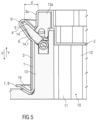
- FIGS. 4 to 7 show sectional views of the tool 10 according to Figure 1 and the container 1 arranged in the tool 10 after its formation and in different positions during its demolding.
- the representations of these figures illustrate the movement of the wall segments 14.1 to 14.n using the example of the wall segment 14.1.
- the wall segment 14.1 moves in the manner shown when the container 1 is demolded, the movement of the wall 14 into the demolding position when the container 1 is demolded being guided by the container 1 itself.
- the container 1 is cooled to a temperature before demolding which allows an elastic deformation of the container 1 at least in the area of the stacking edge 9.
- the stacking edge 9 can deform in accordance with a movement of an outer contour of the wall segments 14.1 to 14.n and then return to its original shape.
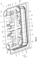
- Figure 8 is a perspective view of a possible further embodiment of a tool 10 for producing the container 1 according to the Figures 1 and 2 shown in a form position.
- Figure 9 shows a perspective view of the tool 10 according to Figure 8 without showing a base section 12 in order to allow a view into the interior of the tool 10.
- the wall 14 for forming the stacking edge 9 comprises several wall segments 14.1 to 14.8 designed as slides, which, starting from their mold position, which corresponds to the mold position of the Figures 3 to 7 corresponding wall segments 14.1 to 14.n, can be moved into an interior of the positive mold 11.
- Four wall segments 14.1 to 14.4 are designed as sliders that can be moved in an inclined, linear manner. These sliders are each coupled to a motorized, hydraulic and/or pneumatic drive 18 to carry out the movement.
- Wall segments 14.5 to 14.8 arranged at corners of the side wall section 13 are designed as so-called gravity slides or gravity slide systems, which are locked in the molding position by the side wall section 13 and the adjacent slides and are released after the linear displacement of the adjacent slides into the interior of the positive mold 11 in such a way that they automatically move into the interior of the positive mold 11 due to the weight force during, or after demolding, for example into a Starting position, move.
- gravity slides or gravity slide systems In other words: In the direction of forming, the linearly movable slides are extended to position and the gravity slides are blocked by frame stops. These also remain in this position during the actual deep-drawing process.
- the blank (not shown in detail) made of plastic, in particular thermoplastic, is first heated in such a way that it is deformable in order to produce the container 1.
- the heating takes place, for example, by means of external heat sources (not shown in detail).
- the blank is then formed using negative pressure and/or a stamp (not shown) in such a way that the plastic is pulled over the positive mold 11 and its outer contour forms an inner contour of the container 1 produced.
- the lower flange 4 i.e. its groove directed inwards and thus towards the positive mold 11, is formed by means of the protruding wall 14.
- the wall 14 is arranged in a molding position for forming the container 1 so as to protrude all the way around the outside of the positive mold 11.
- the angle ⁇ which is smaller than 90°, is formed between a wall side 17 directed towards the base section 12, on which the underside 5 of the stacking edge 9 is formed, and a region 13a of the associated side wall section 13 extending from this wall side 17 in the direction of the base section 12.
- the four wall segments 14.1 to 14.4 designed as linearly movable slides are then first moved inwards into the positive mold 11 and release the long and short sides of the stacking edge 9 shown.
- a movement of the other wall segments 14.5 to 14.8 designed as gravity slides is also released, so that a movement of the container 1 in the demolding direction -Y is released.
- the gravity slides move due to contact friction to the grooves of the stacking edge 9, which form undercut surfaces form, obliquely inwards with the backward movement, so that after a certain distance they leave the undercut area and the container 1 is completely free and demolded.
- FIG. 10 Such a state, in which the four wall segments 14.1 to 14.4 designed as linearly movable slides are moved inwards into the positive mold 11 and release the long and short sides of the stack edge 9, is shown in Figure 10 , in which the tool 10 is shown without the base section 12 in order to allow a view into the interior of the tool 10. After the wall segments 14.1 to 14.4 have moved into the position shown, the movement of the other wall segments 14.5 to 14.8, which are designed as gravity slides, into the interior of the tool 10 is released.
Landscapes
- Engineering & Computer Science (AREA)
- Mechanical Engineering (AREA)
- Ceramic Engineering (AREA)
- Moulds For Moulding Plastics Or The Like (AREA)
- Blow-Moulding Or Thermoforming Of Plastics Or The Like (AREA)
Claims (4)
- Outil (10) pour la fabrication d'un récipient (1) en matière plastique dans un processus de thermoformage, notamment un processus d'emboutissage profond de matière plastique, avec un moule positif (11), comprenant- une section de fond (12) pour la réalisation d'un fond de récipient (2),- une section de paroi latérale (13) pour la réalisation d'une paroi latérale circonférentielle (3), réalisée en un même matériau que le fond de récipient (2),- une paroi (14) pour la réalisation d'un bord d'empilement (9) réalisé sous forme de profil creux, dépassant d'un contour extérieur de la paroi latérale (3) du récipient (1) circonférentiellement autour de tout un côté extérieur de récipient, lequel est réalisé sous forme de rainure ouverte vers l'intérieur vers un côté intérieur de récipient et est agencé à distance du fond de récipient (2),- la paroi (14) étant agencée en saillie circonférentiellement autour de tout un côté extérieur du moule positif (11) dans une position de moulage pour le moulage du récipient (1) et un angle (α) étant formé entre un côté de paroi (17) dirigé vers la section de fond (12) et une zone (13a) de la section de paroi latérale (13) correspondante, s'étendant à partir de ce côté de paroi (17) en direction de la section de fond (12), qui est inférieur à 90°, caractérisé en ce que :- la paroi (14) peut être déplacée de la position de moulage dans une position de démoulage, dans laquelle une distance (d) entre une extrémité de la paroi (14) en saillie dans la position de moulage et la section de paroi latérale (13) est réduite,- la paroi (14) comprend plusieurs segments de paroi (14.1 à 14.4), qui sont agencés respectivement de manière pivotante sur la section de paroi latérale (13),- un déplacement des segments de paroi (14.1 à 14.n) dans la position de moulage est bloqué dans la direction de moulage (Y), qui s'étend le long de la section de paroi latérale (13) en partant de la section de fond (12), et est libéré dans la direction de démoulage (-Y), qui s'étend à l'opposé de la direction de moulage (Y), et- la zone (13a) est réalisée sous forme circonférentielle, qui repose sur les segments de paroi (14.1 à 14.n) dans la position de moulage ceux-ci .
- Outil (10) selon la revendication 1, dans lequel les segments de paroi pivotants (14.1 à 14.n) sont couplés respectivement à au moins un ressort qui exerce une force sur un segment de paroi correspondant (14.1 à 14.n) à l'encontre d'une direction de pivotement.
- Procédé de fabrication d'un récipient au moyen d'un outil (10) selon l'une quelconque des revendications précédentes, dans un processus de thermoformage, notamment un processus d'emboutissage profond de matière plastique,- une ébauche formée de matière plastique thermoplastique étant chauffée,- l'ébauche étant déformée au moyen du moule positif (11), un fond de récipient (2) étant formé à partir de l'ébauche sur la section de fond (12) du moule positif (11), une paroi latérale circonférentielle (3) réalisée en un même matériau que le fond de récipient (2) étant formée sur une section de paroi latérale (13), et un bord d'empilement (9) réalisé sous forme de profil creux, dépassant d'un contour extérieur de la paroi latérale (3) du récipient (1) circonférentiellement autour de tout un côté extérieur de récipient, étant formé sur une paroi (14) agencée sur la section de paroi latérale (13), qui est réalisé sous forme de rainure ouverte vers l'intérieur vers un côté intérieur de récipient et qui est agencé à distance du fond de récipient (2),- la paroi (14) étant agencée en saillie circonférentiellement autour de tout un côté extérieur du moule positif (11) pendant le moulage de l'ébauche pour former le récipient (1) dans une position de moulage, de telle sorte qu'un angle (α) est formé entre un côté de paroi (17) dirigé vers la section de fond (12) et une zone de la section de paroi latérale (13) correspondante, s'étendant à partir de ce côté de paroi (17) en direction de la section de fond (12), qui est inférieur à 90°, caractérisé en ce que :- la zone (13a) réalisée sous forme circonférentielle repose sur les segments de paroi (14.1 à 14.n) dans la position de moulage de ceux-ci,- la paroi (14) est déplacée, après le moulage de l'ébauche, dans une position de démoulage dans laquelle une distance (d) entre une extrémité de la paroi (14) faisant saillie dans la position de moulage et la section de paroi latérale (13) est réduite,- un déplacement de segments de paroi (14.1 à 14.n) de la paroi (14), agencés de manière pivotante dans la section de paroi latérale (13), dans la position de moulage est bloqué dans la direction de moulage (Y), qui s'étend le long de la section de paroi latérale (13) en partant de la section de fond (12), et est libéré dans la direction de démoulage (-Y), qui s'étend à l'opposé de la direction de moulage (Y), et- le déplacement de la paroi (14) dans la position de démoulage lors d'un démoulage du récipient (1) du moule positif (11) est guidé au moyen du récipient (1) .
- Procédé selon la revendication 3, caractérisé en ce que le récipient (1) est refroidi avant le démoulage à une température qui permet une déformation élastique du récipient (1) au moins dans la zone du bord d'empilement (9).
Applications Claiming Priority (2)
| Application Number | Priority Date | Filing Date | Title |
|---|---|---|---|
| DE102019207818.4A DE102019207818A1 (de) | 2019-05-28 | 2019-05-28 | Werkzeug und Verfahren zur Herstellung eines Behälters |
| EP20176469.3A EP3744501B1 (fr) | 2019-05-28 | 2020-05-26 | Outil et procédé de fabrication d'un récipient |
Related Parent Applications (2)
| Application Number | Title | Priority Date | Filing Date |
|---|---|---|---|
| EP20176469.3A Division EP3744501B1 (fr) | 2019-05-28 | 2020-05-26 | Outil et procédé de fabrication d'un récipient |
| EP20176469.3A Division-Into EP3744501B1 (fr) | 2019-05-28 | 2020-05-26 | Outil et procédé de fabrication d'un récipient |
Publications (2)
| Publication Number | Publication Date |
|---|---|
| EP3854567A1 EP3854567A1 (fr) | 2021-07-28 |
| EP3854567B1 true EP3854567B1 (fr) | 2024-04-24 |
Family
ID=71103193
Family Applications (2)
| Application Number | Title | Priority Date | Filing Date |
|---|---|---|---|
| EP20176469.3A Active EP3744501B1 (fr) | 2019-05-28 | 2020-05-26 | Outil et procédé de fabrication d'un récipient |
| EP21163359.9A Active EP3854567B1 (fr) | 2019-05-28 | 2020-05-26 | Outil et procédé de fabrication d'un récipient |
Family Applications Before (1)
| Application Number | Title | Priority Date | Filing Date |
|---|---|---|---|
| EP20176469.3A Active EP3744501B1 (fr) | 2019-05-28 | 2020-05-26 | Outil et procédé de fabrication d'un récipient |
Country Status (5)
| Country | Link |
|---|---|
| US (1) | US11697521B2 (fr) |
| EP (2) | EP3744501B1 (fr) |
| DE (1) | DE102019207818A1 (fr) |
| HU (2) | HUE060289T2 (fr) |
| PL (2) | PL3744501T3 (fr) |
Family Cites Families (23)
| Publication number | Priority date | Publication date | Assignee | Title |
|---|---|---|---|---|
| US3975493A (en) * | 1973-12-03 | 1976-08-17 | The Dow Chemical Company | Method for forming hollow articles from thermoplastic sheeting or film using an expandable plug |
| IT1126638B (it) * | 1979-12-20 | 1986-05-21 | Pier Luigi Nava | Procedimento e relativo utensile per stampare manufatti in resina armata |
| DE3814999A1 (de) | 1988-05-03 | 1989-11-16 | Julius Bauer Gmbh | Vorrichtung zum tiefziehen von stapelbaren paletten |
| US4961700A (en) * | 1988-12-15 | 1990-10-09 | Owens-Corning Fiberglas Corporation | Shaping means for the production of fiber-reinforced preform articles |
| US5198244A (en) | 1992-04-27 | 1993-03-30 | American Sheet Extrusion Corporation | Retractable mold protrusion assembly |
| JPH08127059A (ja) | 1994-10-31 | 1996-05-21 | Toyota Motor Corp | 表皮材の真空成形方法 |
| DE19964255C2 (de) | 1999-06-15 | 2002-07-04 | Wilfried Klein-Neerken | Transportbehälter |
| US7311218B2 (en) * | 2004-05-11 | 2007-12-25 | Sonoco Development, Inc. | Tamper evident closure with reclose feature |
| AU2008351695B2 (en) * | 2008-02-27 | 2014-12-04 | Apc Products Limited | Closures for plastic containers adapted for automated insert molding |
| US9493266B1 (en) * | 2009-02-25 | 2016-11-15 | Silgan Plastic Food Containers Corporation | Molded plastic container |
| US8613358B2 (en) * | 2010-03-18 | 2013-12-24 | Jong Soo Park | Structure for detachable coupling of containers |
| US9016503B2 (en) * | 2011-01-18 | 2015-04-28 | Easypak Llc | Tamper-evident container with multi-action breakaway hinge |
| US9221596B2 (en) * | 2011-02-22 | 2015-12-29 | Graham Packaging Company, L.P. | Plastic aerosol container |
| CN103459119B (zh) * | 2011-03-29 | 2015-09-30 | 赫斯基注塑系统有限公司 | 用于预成形件的模具叠层 |
| ITBZ20120011A1 (it) | 2012-03-21 | 2013-09-22 | Enetec Srl | Dispositivo di formatura sotto vuoto per piastre di supporto per tubi flessibili |
| KR101681292B1 (ko) * | 2012-08-09 | 2016-12-01 | 닛세이 에이. 에스. 비 기카이 가부시키가이샤 | 블로우 노즐 및 블로우 성형기 |
| US9187209B1 (en) * | 2013-07-05 | 2015-11-17 | Highland Packaging Solutions, Inc. | Tamper evident container having tear tab and hinged lid |
| US20150298871A1 (en) * | 2015-04-20 | 2015-10-22 | 9065-3395 Quebec Inc. | Container and lid assembly |
| US9796511B2 (en) * | 2015-06-30 | 2017-10-24 | Anchor Packaging, Inc. | Tamper evident plastic food container |
| ES2848175T3 (es) * | 2015-08-31 | 2021-08-05 | Converter Mfg Llc | Artículo termoplástico conformado con bordes lisos |
| CA3017353A1 (fr) * | 2016-03-11 | 2017-09-14 | Ring Container Technologies, Llc | Procede de fabrication d'un recipient |
| BR112018070424B1 (pt) * | 2016-04-06 | 2022-08-30 | Amcor Rigid Plastics Usa, Llc | Métodos de formação de uma pré-forma |
| US11376768B2 (en) * | 2019-01-16 | 2022-07-05 | Tekni-Plex, Inc. | Packaging tray and method of manufacture |
-
2019
- 2019-05-28 DE DE102019207818.4A patent/DE102019207818A1/de not_active Ceased
-
2020
- 2020-05-19 US US16/877,888 patent/US11697521B2/en active Active
- 2020-05-26 EP EP20176469.3A patent/EP3744501B1/fr active Active
- 2020-05-26 HU HUE20176469A patent/HUE060289T2/hu unknown
- 2020-05-26 EP EP21163359.9A patent/EP3854567B1/fr active Active
- 2020-05-26 PL PL20176469.3T patent/PL3744501T3/pl unknown
- 2020-05-26 HU HUE21163359A patent/HUE067755T2/hu unknown
- 2020-05-26 PL PL21163359.9T patent/PL3854567T3/pl unknown
Also Published As
| Publication number | Publication date |
|---|---|
| PL3854567T3 (pl) | 2024-08-19 |
| US20200377253A1 (en) | 2020-12-03 |
| HUE060289T2 (hu) | 2023-02-28 |
| PL3744501T3 (pl) | 2022-11-21 |
| EP3744501B1 (fr) | 2022-07-27 |
| US11697521B2 (en) | 2023-07-11 |
| HUE067755T2 (hu) | 2024-11-28 |
| EP3854567A1 (fr) | 2021-07-28 |
| DE102019207818A1 (de) | 2020-12-03 |
| EP3744501A1 (fr) | 2020-12-02 |
Similar Documents
| Publication | Publication Date | Title |
|---|---|---|
| DE4224009B4 (de) | Verfahren und Vorrichtung zum Herstellen von hohlen, mit einem Boden versehenen Gegenständen | |
| DE3347233C2 (de) | Maschine zum Herstellen von zweischichtigen Hohlkörpern | |
| DE69415143T2 (de) | Verfahren, vorrichtung und werkzeug zum spritzgiessen einer vorform | |
| WO2014191360A1 (fr) | Mécanisme de démoulage d'un outil de moulage par injection | |
| DE3433661A1 (de) | Verfahren und vorrichtung zum formpressen von teilen, die mit einer extrem glatten oberflaeche versehen sind | |
| EP0147571A2 (fr) | Outil pour mouler par injection des objets en matière plastique | |
| EP1782936B1 (fr) | Dispositif de moulage par injection | |
| DE2440900C2 (de) | Spritzgiessform zum herstellen von kastenfoermigen behaeltern, insbesondere von flaschentransportkaesten | |
| EP3708328B1 (fr) | Outil de moulage par injection des pièces moulées en matière plastique et procédé de déplacement d'un coulisseau d'une moitié d'outil | |
| CH711891A2 (de) | Vorrichtung zur Herstellung eines Verbundformteils und Verfahren zur Herstellung eines entsprechenden Verbundformteils. | |
| DE102011113328B4 (de) | Formverfahren unter Verwendung eines Formgedächtnispolymers | |
| EP1060063B1 (fr) | Dispositif pour recevoir et transporter des pieces moulees | |
| EP3147226B1 (fr) | Procede de fabrication d'au moins un espace libre dans une enveloppe constituee de feuille retractable, bloquant une pile de marchandises disposee sur une palette, et dispositif de formage destine a l'execution du procede | |
| EP3744501B1 (fr) | Outil et procédé de fabrication d'un récipient | |
| AT512210B1 (de) | Spritzgiesswerkzeug, insbesondere backenwerkzeug | |
| EP0706875A1 (fr) | Procédé, galet moulé par injection et moule d'injection pour fabriquer un galet | |
| EP0595203B1 (fr) | Dispositif de moulage par injection | |
| WO2012034614A1 (fr) | Outil de moulage par soufflage comportant une partie de moule pouvant être soulevée | |
| DE19603733A1 (de) | Verfahren zum Herstellen eines Produktes aus Kunststoff durch Spritzgießen, sowie nach diesem Verfahren hergestelltes Produkt | |
| DE69729408T2 (de) | Verfahren und Vorrichtung zum Herstellen gestapelter Deckel und so hergestellte Deckel | |
| EP0738661A1 (fr) | Palette en matière plastique, procèdè et dispositif pour sa fabrication | |
| EP1029796A1 (fr) | Récipient en matière plastique et méthode et dispositif pour sa production et manipulation | |
| DE69903326T2 (de) | Vulkanisierformwerkzeug für Luftreifen | |
| DE3814999A1 (de) | Vorrichtung zum tiefziehen von stapelbaren paletten | |
| DE102015004232B4 (de) | Verfahren zur Umformung eines flächigen Halbzeugs zu einer dreidimensionalen Hohlkörperkontur |
Legal Events
| Date | Code | Title | Description |
|---|---|---|---|
| PUAI | Public reference made under article 153(3) epc to a published international application that has entered the european phase |
Free format text: ORIGINAL CODE: 0009012 |
|
| STAA | Information on the status of an ep patent application or granted ep patent |
Free format text: STATUS: THE APPLICATION HAS BEEN PUBLISHED |
|
| AC | Divisional application: reference to earlier application |
Ref document number: 3744501 Country of ref document: EP Kind code of ref document: P |
|
| AK | Designated contracting states |
Kind code of ref document: A1 Designated state(s): AL AT BE BG CH CY CZ DE DK EE ES FI FR GB GR HR HU IE IS IT LI LT LU LV MC MK MT NL NO PL PT RO RS SE SI SK SM TR |
|
| STAA | Information on the status of an ep patent application or granted ep patent |
Free format text: STATUS: REQUEST FOR EXAMINATION WAS MADE |
|
| 17P | Request for examination filed |
Effective date: 20220121 |
|
| RBV | Designated contracting states (corrected) |
Designated state(s): AL AT BE BG CH CY CZ DE DK EE ES FI FR GB GR HR HU IE IS IT LI LT LU LV MC MK MT NL NO PL PT RO RS SE SI SK SM TR |
|
| GRAP | Despatch of communication of intention to grant a patent |
Free format text: ORIGINAL CODE: EPIDOSNIGR1 |
|
| STAA | Information on the status of an ep patent application or granted ep patent |
Free format text: STATUS: GRANT OF PATENT IS INTENDED |
|
| RIC1 | Information provided on ipc code assigned before grant |
Ipc: B29L 31/00 20060101ALN20231129BHEP Ipc: B65D 1/26 20060101ALN20231129BHEP Ipc: B29C 51/08 20060101ALN20231129BHEP Ipc: B65D 21/02 20060101ALI20231129BHEP Ipc: B29C 51/34 20060101AFI20231129BHEP |
|
| INTG | Intention to grant announced |
Effective date: 20231213 |
|
| GRAS | Grant fee paid |
Free format text: ORIGINAL CODE: EPIDOSNIGR3 |
|
| GRAA | (expected) grant |
Free format text: ORIGINAL CODE: 0009210 |
|
| STAA | Information on the status of an ep patent application or granted ep patent |
Free format text: STATUS: THE PATENT HAS BEEN GRANTED |
|
| AC | Divisional application: reference to earlier application |
Ref document number: 3744501 Country of ref document: EP Kind code of ref document: P |
|
| AK | Designated contracting states |
Kind code of ref document: B1 Designated state(s): AL AT BE BG CH CY CZ DE DK EE ES FI FR GB GR HR HU IE IS IT LI LT LU LV MC MK MT NL NO PL PT RO RS SE SI SK SM TR |
|
| P01 | Opt-out of the competence of the unified patent court (upc) registered |
Effective date: 20240320 |
|
| REG | Reference to a national code |
Ref country code: GB Ref legal event code: FG4D Free format text: NOT ENGLISH |
|
| REG | Reference to a national code |
Ref country code: CH Ref legal event code: EP |
|
| REG | Reference to a national code |
Ref country code: DE Ref legal event code: R096 Ref document number: 502020007795 Country of ref document: DE |
|
| REG | Reference to a national code |
Ref country code: IE Ref legal event code: FG4D Free format text: LANGUAGE OF EP DOCUMENT: GERMAN |
|
| REG | Reference to a national code |
Ref country code: LT Ref legal event code: MG9D |
|
| REG | Reference to a national code |
Ref country code: NL Ref legal event code: FP |
|
| REG | Reference to a national code |
Ref country code: SK Ref legal event code: T3 Ref document number: E 44593 Country of ref document: SK |
|
| PG25 | Lapsed in a contracting state [announced via postgrant information from national office to epo] |
Ref country code: IS Free format text: LAPSE BECAUSE OF FAILURE TO SUBMIT A TRANSLATION OF THE DESCRIPTION OR TO PAY THE FEE WITHIN THE PRESCRIBED TIME-LIMIT Effective date: 20240824 |
|
| PG25 | Lapsed in a contracting state [announced via postgrant information from national office to epo] |
Ref country code: BG Free format text: LAPSE BECAUSE OF FAILURE TO SUBMIT A TRANSLATION OF THE DESCRIPTION OR TO PAY THE FEE WITHIN THE PRESCRIBED TIME-LIMIT Effective date: 20240424 |
|
| PG25 | Lapsed in a contracting state [announced via postgrant information from national office to epo] |
Ref country code: HR Free format text: LAPSE BECAUSE OF FAILURE TO SUBMIT A TRANSLATION OF THE DESCRIPTION OR TO PAY THE FEE WITHIN THE PRESCRIBED TIME-LIMIT Effective date: 20240424 Ref country code: FI Free format text: LAPSE BECAUSE OF FAILURE TO SUBMIT A TRANSLATION OF THE DESCRIPTION OR TO PAY THE FEE WITHIN THE PRESCRIBED TIME-LIMIT Effective date: 20240424 |
|
| PG25 | Lapsed in a contracting state [announced via postgrant information from national office to epo] |
Ref country code: GR Free format text: LAPSE BECAUSE OF FAILURE TO SUBMIT A TRANSLATION OF THE DESCRIPTION OR TO PAY THE FEE WITHIN THE PRESCRIBED TIME-LIMIT Effective date: 20240725 |
|
| PG25 | Lapsed in a contracting state [announced via postgrant information from national office to epo] |
Ref country code: PT Free format text: LAPSE BECAUSE OF FAILURE TO SUBMIT A TRANSLATION OF THE DESCRIPTION OR TO PAY THE FEE WITHIN THE PRESCRIBED TIME-LIMIT Effective date: 20240826 |
|
| PG25 | Lapsed in a contracting state [announced via postgrant information from national office to epo] |
Ref country code: ES Free format text: LAPSE BECAUSE OF FAILURE TO SUBMIT A TRANSLATION OF THE DESCRIPTION OR TO PAY THE FEE WITHIN THE PRESCRIBED TIME-LIMIT Effective date: 20240424 |
|
| PG25 | Lapsed in a contracting state [announced via postgrant information from national office to epo] |
Ref country code: LV Free format text: LAPSE BECAUSE OF FAILURE TO SUBMIT A TRANSLATION OF THE DESCRIPTION OR TO PAY THE FEE WITHIN THE PRESCRIBED TIME-LIMIT Effective date: 20240424 |
|
| PG25 | Lapsed in a contracting state [announced via postgrant information from national office to epo] |
Ref country code: PT Free format text: LAPSE BECAUSE OF FAILURE TO SUBMIT A TRANSLATION OF THE DESCRIPTION OR TO PAY THE FEE WITHIN THE PRESCRIBED TIME-LIMIT Effective date: 20240826 Ref country code: NO Free format text: LAPSE BECAUSE OF FAILURE TO SUBMIT A TRANSLATION OF THE DESCRIPTION OR TO PAY THE FEE WITHIN THE PRESCRIBED TIME-LIMIT Effective date: 20240724 Ref country code: LV Free format text: LAPSE BECAUSE OF FAILURE TO SUBMIT A TRANSLATION OF THE DESCRIPTION OR TO PAY THE FEE WITHIN THE PRESCRIBED TIME-LIMIT Effective date: 20240424 Ref country code: IS Free format text: LAPSE BECAUSE OF FAILURE TO SUBMIT A TRANSLATION OF THE DESCRIPTION OR TO PAY THE FEE WITHIN THE PRESCRIBED TIME-LIMIT Effective date: 20240824 Ref country code: HR Free format text: LAPSE BECAUSE OF FAILURE TO SUBMIT A TRANSLATION OF THE DESCRIPTION OR TO PAY THE FEE WITHIN THE PRESCRIBED TIME-LIMIT Effective date: 20240424 Ref country code: GR Free format text: LAPSE BECAUSE OF FAILURE TO SUBMIT A TRANSLATION OF THE DESCRIPTION OR TO PAY THE FEE WITHIN THE PRESCRIBED TIME-LIMIT Effective date: 20240725 Ref country code: FI Free format text: LAPSE BECAUSE OF FAILURE TO SUBMIT A TRANSLATION OF THE DESCRIPTION OR TO PAY THE FEE WITHIN THE PRESCRIBED TIME-LIMIT Effective date: 20240424 Ref country code: ES Free format text: LAPSE BECAUSE OF FAILURE TO SUBMIT A TRANSLATION OF THE DESCRIPTION OR TO PAY THE FEE WITHIN THE PRESCRIBED TIME-LIMIT Effective date: 20240424 Ref country code: BG Free format text: LAPSE BECAUSE OF FAILURE TO SUBMIT A TRANSLATION OF THE DESCRIPTION OR TO PAY THE FEE WITHIN THE PRESCRIBED TIME-LIMIT Effective date: 20240424 Ref country code: RS Free format text: LAPSE BECAUSE OF FAILURE TO SUBMIT A TRANSLATION OF THE DESCRIPTION OR TO PAY THE FEE WITHIN THE PRESCRIBED TIME-LIMIT Effective date: 20240724 |
|
| REG | Reference to a national code |
Ref country code: HU Ref legal event code: AG4A Ref document number: E067755 Country of ref document: HU |
|
| PG25 | Lapsed in a contracting state [announced via postgrant information from national office to epo] |
Ref country code: DK Free format text: LAPSE BECAUSE OF FAILURE TO SUBMIT A TRANSLATION OF THE DESCRIPTION OR TO PAY THE FEE WITHIN THE PRESCRIBED TIME-LIMIT Effective date: 20240424 |
|
| PG25 | Lapsed in a contracting state [announced via postgrant information from national office to epo] |
Ref country code: LU Free format text: LAPSE BECAUSE OF NON-PAYMENT OF DUE FEES Effective date: 20240526 |
|
| PG25 | Lapsed in a contracting state [announced via postgrant information from national office to epo] |
Ref country code: EE Free format text: LAPSE BECAUSE OF FAILURE TO SUBMIT A TRANSLATION OF THE DESCRIPTION OR TO PAY THE FEE WITHIN THE PRESCRIBED TIME-LIMIT Effective date: 20240424 |
|
| PG25 | Lapsed in a contracting state [announced via postgrant information from national office to epo] |
Ref country code: RO Free format text: LAPSE BECAUSE OF FAILURE TO SUBMIT A TRANSLATION OF THE DESCRIPTION OR TO PAY THE FEE WITHIN THE PRESCRIBED TIME-LIMIT Effective date: 20240424 |
|
| REG | Reference to a national code |
Ref country code: DE Ref legal event code: R097 Ref document number: 502020007795 Country of ref document: DE |
|
| PG25 | Lapsed in a contracting state [announced via postgrant information from national office to epo] |
Ref country code: SM Free format text: LAPSE BECAUSE OF FAILURE TO SUBMIT A TRANSLATION OF THE DESCRIPTION OR TO PAY THE FEE WITHIN THE PRESCRIBED TIME-LIMIT Effective date: 20240424 |
|
| PG25 | Lapsed in a contracting state [announced via postgrant information from national office to epo] |
Ref country code: SM Free format text: LAPSE BECAUSE OF FAILURE TO SUBMIT A TRANSLATION OF THE DESCRIPTION OR TO PAY THE FEE WITHIN THE PRESCRIBED TIME-LIMIT Effective date: 20240424 Ref country code: RO Free format text: LAPSE BECAUSE OF FAILURE TO SUBMIT A TRANSLATION OF THE DESCRIPTION OR TO PAY THE FEE WITHIN THE PRESCRIBED TIME-LIMIT Effective date: 20240424 Ref country code: LU Free format text: LAPSE BECAUSE OF NON-PAYMENT OF DUE FEES Effective date: 20240526 Ref country code: EE Free format text: LAPSE BECAUSE OF FAILURE TO SUBMIT A TRANSLATION OF THE DESCRIPTION OR TO PAY THE FEE WITHIN THE PRESCRIBED TIME-LIMIT Effective date: 20240424 Ref country code: DK Free format text: LAPSE BECAUSE OF FAILURE TO SUBMIT A TRANSLATION OF THE DESCRIPTION OR TO PAY THE FEE WITHIN THE PRESCRIBED TIME-LIMIT Effective date: 20240424 Ref country code: MC Free format text: LAPSE BECAUSE OF FAILURE TO SUBMIT A TRANSLATION OF THE DESCRIPTION OR TO PAY THE FEE WITHIN THE PRESCRIBED TIME-LIMIT Effective date: 20240424 |
|
| REG | Reference to a national code |
Ref country code: BE Ref legal event code: MM Effective date: 20240531 |
|
| PLBE | No opposition filed within time limit |
Free format text: ORIGINAL CODE: 0009261 |
|
| STAA | Information on the status of an ep patent application or granted ep patent |
Free format text: STATUS: NO OPPOSITION FILED WITHIN TIME LIMIT |
|
| 26N | No opposition filed |
Effective date: 20250127 |
|
| PG25 | Lapsed in a contracting state [announced via postgrant information from national office to epo] |
Ref country code: IE Free format text: LAPSE BECAUSE OF NON-PAYMENT OF DUE FEES Effective date: 20240526 |
|
| PG25 | Lapsed in a contracting state [announced via postgrant information from national office to epo] |
Ref country code: SI Free format text: LAPSE BECAUSE OF FAILURE TO SUBMIT A TRANSLATION OF THE DESCRIPTION OR TO PAY THE FEE WITHIN THE PRESCRIBED TIME-LIMIT Effective date: 20240424 Ref country code: BE Free format text: LAPSE BECAUSE OF NON-PAYMENT OF DUE FEES Effective date: 20240531 |
|
| PGFP | Annual fee paid to national office [announced via postgrant information from national office to epo] |
Ref country code: NL Payment date: 20250522 Year of fee payment: 6 |
|
| PGFP | Annual fee paid to national office [announced via postgrant information from national office to epo] |
Ref country code: PL Payment date: 20250514 Year of fee payment: 6 Ref country code: DE Payment date: 20250327 Year of fee payment: 6 |
|
| PGFP | Annual fee paid to national office [announced via postgrant information from national office to epo] |
Ref country code: GB Payment date: 20250522 Year of fee payment: 6 |
|
| PGFP | Annual fee paid to national office [announced via postgrant information from national office to epo] |
Ref country code: HU Payment date: 20250519 Year of fee payment: 6 |
|
| PGFP | Annual fee paid to national office [announced via postgrant information from national office to epo] |
Ref country code: FR Payment date: 20250521 Year of fee payment: 6 |
|
| PGFP | Annual fee paid to national office [announced via postgrant information from national office to epo] |
Ref country code: CH Payment date: 20250601 Year of fee payment: 6 |
|
| PGFP | Annual fee paid to national office [announced via postgrant information from national office to epo] |
Ref country code: AT Payment date: 20250519 Year of fee payment: 6 |
|
| PGFP | Annual fee paid to national office [announced via postgrant information from national office to epo] |
Ref country code: SK Payment date: 20250520 Year of fee payment: 6 |
|
| PGFP | Annual fee paid to national office [announced via postgrant information from national office to epo] |
Ref country code: CZ Payment date: 20250514 Year of fee payment: 6 |
|
| PG25 | Lapsed in a contracting state [announced via postgrant information from national office to epo] |
Ref country code: SE Free format text: LAPSE BECAUSE OF FAILURE TO SUBMIT A TRANSLATION OF THE DESCRIPTION OR TO PAY THE FEE WITHIN THE PRESCRIBED TIME-LIMIT Effective date: 20240424 |
|
| PG25 | Lapsed in a contracting state [announced via postgrant information from national office to epo] |
Ref country code: CY Free format text: LAPSE BECAUSE OF FAILURE TO SUBMIT A TRANSLATION OF THE DESCRIPTION OR TO PAY THE FEE WITHIN THE PRESCRIBED TIME-LIMIT; INVALID AB INITIO Effective date: 20200526 |
|
| PG25 | Lapsed in a contracting state [announced via postgrant information from national office to epo] |
Ref country code: IT Free format text: LAPSE BECAUSE OF FAILURE TO SUBMIT A TRANSLATION OF THE DESCRIPTION OR TO PAY THE FEE WITHIN THE PRESCRIBED TIME-LIMIT Effective date: 20240424 |