EP3854573A1 - Procédé de production de pneu et pneu cru - Google Patents
Procédé de production de pneu et pneu cru Download PDFInfo
- Publication number
- EP3854573A1 EP3854573A1 EP20217498.3A EP20217498A EP3854573A1 EP 3854573 A1 EP3854573 A1 EP 3854573A1 EP 20217498 A EP20217498 A EP 20217498A EP 3854573 A1 EP3854573 A1 EP 3854573A1
- Authority
- EP
- European Patent Office
- Prior art keywords
- tire
- rubber sheet
- pair
- inner liner
- production method
- Prior art date
- Legal status (The legal status is an assumption and is not a legal conclusion. Google has not performed a legal analysis and makes no representation as to the accuracy of the status listed.)
- Granted
Links
Images



Classifications
-
- B—PERFORMING OPERATIONS; TRANSPORTING
- B29—WORKING OF PLASTICS; WORKING OF SUBSTANCES IN A PLASTIC STATE IN GENERAL
- B29D—PRODUCING PARTICULAR ARTICLES FROM PLASTICS OR FROM SUBSTANCES IN A PLASTIC STATE
- B29D30/00—Producing pneumatic or solid tyres or parts thereof
- B29D30/06—Pneumatic tyres or parts thereof (e.g. produced by casting, moulding, compression moulding, injection moulding, centrifugal casting)
- B29D30/0681—Parts of pneumatic tyres; accessories, auxiliary operations
-
- B—PERFORMING OPERATIONS; TRANSPORTING
- B29—WORKING OF PLASTICS; WORKING OF SUBSTANCES IN A PLASTIC STATE IN GENERAL
- B29D—PRODUCING PARTICULAR ARTICLES FROM PLASTICS OR FROM SUBSTANCES IN A PLASTIC STATE
- B29D30/00—Producing pneumatic or solid tyres or parts thereof
- B29D30/06—Pneumatic tyres or parts thereof (e.g. produced by casting, moulding, compression moulding, injection moulding, centrifugal casting)
- B29D30/0601—Vulcanising tyres; Vulcanising presses for tyres
-
- B—PERFORMING OPERATIONS; TRANSPORTING
- B29—WORKING OF PLASTICS; WORKING OF SUBSTANCES IN A PLASTIC STATE IN GENERAL
- B29D—PRODUCING PARTICULAR ARTICLES FROM PLASTICS OR FROM SUBSTANCES IN A PLASTIC STATE
- B29D30/00—Producing pneumatic or solid tyres or parts thereof
- B29D30/06—Pneumatic tyres or parts thereof (e.g. produced by casting, moulding, compression moulding, injection moulding, centrifugal casting)
- B29D30/08—Building tyres
-
- B—PERFORMING OPERATIONS; TRANSPORTING
- B60—VEHICLES IN GENERAL
- B60C—VEHICLE TYRES; TYRE INFLATION; TYRE CHANGING; CONNECTING VALVES TO INFLATABLE ELASTIC BODIES IN GENERAL; DEVICES OR ARRANGEMENTS RELATED TO TYRES
- B60C9/00—Reinforcements or ply arrangement of pneumatic tyres
- B60C9/18—Structure or arrangement of belts or breakers, crown-reinforcing or cushioning layers
-
- B—PERFORMING OPERATIONS; TRANSPORTING
- B29—WORKING OF PLASTICS; WORKING OF SUBSTANCES IN A PLASTIC STATE IN GENERAL
- B29D—PRODUCING PARTICULAR ARTICLES FROM PLASTICS OR FROM SUBSTANCES IN A PLASTIC STATE
- B29D30/00—Producing pneumatic or solid tyres or parts thereof
- B29D30/06—Pneumatic tyres or parts thereof (e.g. produced by casting, moulding, compression moulding, injection moulding, centrifugal casting)
- B29D30/0681—Parts of pneumatic tyres; accessories, auxiliary operations
- B29D2030/0682—Inner liners
Definitions
- the present invention relates to a tire production method and a green tire.
- Japanese Laid-Open Patent Publication No. H7-32813 discloses an unvulcanized green tire having an air-impermeable inner liner.
- the inner liner is configured such that the average thickness T1 of the middle portion of the crown, the average thickness T2 of a portion extending over a part of the sidewall portion from the shoulder portion, and the average thickness T3 of the remaining part of the sidewall portion satisfy the following formulas (1) and (2).
- T 2 1.3 ⁇ T 1 to 2.2 ⁇ T 1
- T 3 0.8 ⁇ T 1 to 1.0 ⁇ T 1
- the inner liner when vulcanization is performed with a bladder pressed against the inner liner, the inner liner will have a uniform thickness.
- a belt layer having high stiffness is provided in the tread portion of a tire.
- the present inventors have found that when a green tire is pressed by a bladder from the tire inner cavity side, there is a difference in the deformation amount of the bladder between where the belt layer is provided and where the belt layer is not provided.
- the belt layer which poses such a problem, is not taken into account, and therefore, there is room for consideration regarding making the thickness of the inner liner uniform.
- the present invention has been made in view of the above circumstances, and an object of the present invention is to provide a tire production method and green tire that allow the thickness of an inner liner to be made uniform.
- the present invention is directed to a tire production method including a forming step of forming a green tire including an inner liner extending toroidally between a pair of bead portions, and a belt layer disposed outward of the inner liner in a tire radial direction and in a tread portion, and a vulcanization step of pressing the green tire by a bladder from a tire inner cavity side to obtain a vulcanized tire.
- the inner liner includes a base portion, and a pair of thick portions having a thickness larger than that of the base portion, and the green tire is formed such that the pair of thick portions do not overlap with the belt layer in a tire radial-ply direction.
- the pair of thick portions are preferably located at a pair of shoulder portions, respectively, of the vulcanized tire.
- the pair of thick portions are preferably located outward of respective tire maximum width positions of the vulcanized tire in the tire radial direction.
- the inner liner preferably includes a first rubber sheet and a second rubber sheet attached to the first rubber sheet, the first rubber sheet preferably forms the base portion, and a portion in which the first rubber sheet and the second rubber sheet are attached together preferably forms each thick portion.
- the first rubber sheet preferably has a thickness of 1.0 to 1.5 mm.
- the second rubber sheet preferably has a thickness of 0.8 to 2.0 mm.
- the second rubber sheet preferably has an overlap portion in which end portions thereof in a tire circumferential direction are put on top of each other, and a length in the tire circumferential direction of the overlap portion preferably corresponds to 30 degrees or less around a center of rotation of the green tire.
- the overlap portion is preferably located ⁇ 10 degrees away from a light point of the green tire in the tire circumferential direction.
- the present invention is also directed to an unvulcanized green tire including an inner liner extending toroidally between a pair of bead portions, and a belt layer disposed outward of the inner liner in a tire radial direction and in a tread portion.
- the inner liner includes a base portion and a pair of thick portions having a thickness larger than that of the base portion, and the pair of thick portions are located so as not to overlap with the belt layer in a tire radial-ply direction.
- the inner liner in the forming step of forming a green tire, includes a base portion and a pair of thick portions having a thickness larger than that of the base portion, and the pair of thick portions do not overlap with the belt layer in a tire radial-ply direction. Therefore, for a tire produced by the tire production method of the present invention, the pair of thick portions are stretched by the bladder more than the base portion in the vulcanization step, and therefore, the inner liner has a uniform thickness.
- the inner liner includes a base portion and a pair of thick portions having a thickness larger than that of the base portion, and the pair of thick portions are located so as to not overlap with the belt layer in a tire radial-ply direction.
- the pair of thick portions will be stretched more than the base portion. Therefore, when the green tire of the present invention is vulcanized, the inner liner will have a uniform thickness.
- FIG. 1 is a tire meridional cross-sectional view of a tire 1 produced by a tire production method (hereinafter, sometimes referred to simply as a "production method") according to the present embodiment.
- FIG. 1 shows a pneumatic tire for a passenger car. Note that the present invention is applicable to production methods for pneumatic tires for motorcycles, heavy-duty vehicles, etc., in addition to passenger cars.
- the tire 1 of the present embodiment includes an inner liner 9 which extends toroidally between a pair of bead portions 4, and a belt layer 7 which is disposed outward of the inner liner 9 in the tire radial direction and in a tread portion 2.
- the tire 1 also includes, for example, a tread rubber 2G, a side wall rubber 3G, a bead core 5, a carcass 6, a bead apex rubber 8, etc.
- the carcass 6 is, for example, formed by a well-known carcass ply 6A including a body portion 6a extending between the bead cores 5, and a pair of turned-up portions 6b connected to the body portion 6a.
- a well-known carcass ply 6A including a body portion 6a extending between the bead cores 5, and a pair of turned-up portions 6b connected to the body portion 6a.
- the tread rubber 2G, the side wall rubber 3G, the bead core 5, and the bead apex rubber 8 those having a well-known structure are employed, as appropriate, for example.
- the belt layer 7 of the present embodiment is formed by two belt plies 7A and 7B which are an inner and an outer belt ply arranged in the tire radial direction.
- the inner belt ply 7A is formed so as to have a larger length in the tire axial direction than that of the outer belt ply 7B.
- the belt plies 7A and 7B each have, for example, steel cords arranged at an angle of 45 to 75° with respect to the tire circumferential direction. Note that the belt plies 7A and 7B are not limited to such an embodiment.
- the inner liner 9 of the present embodiment is formed from a rubber having excellent air impermeability.
- the inner liner 9 is, for example, located inward of the carcass 6 in the tire radial direction to form a tire inner cavity surface 1b.
- the production method of the present embodiment includes a forming step S1 of forming an unvulcanized green tire 1A (shown in FIG. 4 ), and a vulcanization step S2 of vulcanizing the green tire 1A to obtain a vulcanized tire (tire) 1.
- the term "unvulcanized” encompasses all states in which vulcanization is not completed, and a so-called half-vulcanized state is among "unvulcanized” states.
- the forming step S1 of the present embodiment includes a first step N1 of wrapping the inner liner 9 around a forming drum 30 to form a first formed body 25 (shown in FIG. 2 ), and a second step N2 of attaching the belt layer 7 to the first formed body 25 to form the green tire 1A (shown in FIG. 3 ).
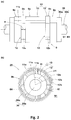
- FIG. 2(a) is a plan view of the forming drum 30, and FIG. 2(b) is a cross-sectional view of the forming drum 30.
- the forming drum 30 has, for example, a well-known cylindrical structure having a wrapping surface 30a on which the inner liner 9 is wrapped, and a rotatable support shaft 30b which supports the wrapping surface 30a.
- a rubber sheet 10 which forms the inner liner 9 is wrapped.
- the rubber sheet 10 of the present embodiment includes a first rubber sheet 11, and a second rubber sheet 12 attached to the first rubber sheet 11.
- the second rubber sheet 12 has, for example, a width (a length in the axial direction of the forming drum 30) w smaller than that of the first rubber sheet 11.
- the first rubber sheet 11 is formed from, for example, a butyl-based rubber having excellent air impermeability.
- the second rubber sheet 12 is preferably formed from, for example, a rubber including a compound that has suitable rubber strength, reversion resistance, crack growth resistance, tear strength, and cord adhesion properties. Note that the second rubber sheet 12 may be formed from the same rubber as that of the first rubber sheet 11.
- the first rubber sheet 11 is wrapped on the wrapping surface 30a of the forming drum 30.
- the first rubber sheet 11 includes an overlap portion 11s in which a wrapping starting end portion 11a and a wrapping terminating end portion 11b are put on top of each other in the radial direction of the forming drum 30.
- the first rubber sheet 11 is formed in a cylindrical shape.
- the wrapping starting end portion 11a and the wrapping terminating end portion 11b together form an end portion in the tire circumferential direction.
- the second rubber sheet 12 is wrapped on the first rubber sheet 11.
- two second rubber sheets 12 are used.
- the second rubber sheets 12 are wrapped so as to be spaced from each other in the axial direction of the forming drum 30.
- the inner liner 9 of the present embodiment includes a base portion 9a which is located between the second rubber sheets 12 and is formed only by the first rubber sheet 11, and a pair of thick portions 9b and 9b each of which is formed as an attachment portion 13 in which the first rubber sheet 11 and the second rubber sheet 12 are attached together.
- the inner liner 9 of the present embodiment includes a pair of outer portions 9c which are located outward of the second rubber sheets 12 in the axial direction of the forming drum 30 and are formed only by the first rubber sheet 11.
- the outer portions 9c have, for example, the same thickness as that of the base portion 9a. Note that the outer portions 9c are not limited to such an embodiment.
- the second rubber sheet 12 includes an overlap portion 12s in which a wrapping starting end portion 12a and a wrapping terminating end portion 12b are put on top of each other in the radial direction of the forming drum 30.
- the wrapping starting end portion 12a and the wrapping terminating end portion 12b together form an end portion in the tire circumferential direction.
- the overlap portion 11s of the first rubber sheet 11 and the overlap portion 12s of the second rubber sheet 12 are preferably formed at different positions in the circumferential direction of the forming drum 30.
- An angle ⁇ 1 between the overlap portion 11s of the first rubber sheet 11 and the overlap portion 12s of the second rubber sheet 12 in the circumferential direction of the forming drum 30 is, for example, but not limited to, preferably not less than 30 degrees, more preferably not less than 60 degrees, and even more preferably not less than 90 degrees.
- the first rubber sheet 11 preferably has a thickness t1 of 1.0 to 1.5 mm.
- the first rubber sheet 11 thus configured serves to inhibit the transparency (called "open thread") of the carcass 6 to maintain the air impermeability of the tire 1 while reducing the mass of the tire 1.
- the tire 1 having a reduced mass has excellent rolling resistance.
- the second rubber sheet 12 preferably has a thickness t2 of 0.8 to 2.0 mm.
- the second rubber sheet 12 thus configured serves to ensure the thickness (t1 + t2) of the thick portions 9b to maintain the air impermeability of the inner liner 9 extended due to vulcanization.
- the second rubber sheet 12 having the thickness t2 inhibits air from being retained at and near the overlap portion 12s.
- the width w of the second rubber sheet 12 is, but not limited to, preferably not less than 5%, more preferably not less than 7%, and even more preferably not less than 10% of a tire cross-sectional height (shown in FIG. 1 ) H of the vulcanized tire 1.
- the width w of the second rubber sheet 12 is preferably not greater than 70%, more preferably not greater than 50%, and even more preferably not greater than 20% of the tire cross-sectional height H of the vulcanized tire 1.
- the carcass ply 6A is wrapped on the outer side of the inner liner 9.
- the side wall rubber 3G, the bead apex rubber 8, and the bead core 5 are further placed on the outer side of the carcass ply 6A.
- the cylindrical first formed body 25 is formed.
- the first formed body 25 is toroidally expanded using a shaping device 31 having a well-known structure.
- FIG. 3 is a cross-sectional view of the first formed body 25 for describing the second step N2.
- the belt plies 7A and 7B are attached to the first formed body 25 expanded toroidally.
- the belt plies 7A and 7B are placed so as not to overlap with the pair of thick portions 9b and 9b in a tire radial-ply direction F.
- the "tire radial-ply direction F” refers to a direction along the body portion 6a of the carcass ply 6A as indicated by an arrow in FIG. 4 .
- the "not overlap” means that the belt plies 7A and 7B do not overlap with the thick portions 9b in a direction perpendicular to the tire radial-ply direction F.
- a tread rubber 2G having a well-known structure (shown in FIG. 4 ) is attached to the outer side of the belt plies 7A and 7B.
- the cylindrical green tire 1A is formed.
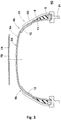
- FIG. 4 is a tire meridional cross-sectional view of the green tire 1A formed in the forming step S1, taken along the center of rotation (not shown) of the green tire 1A.
- the thick portions 9b are preferably located at respective shoulder portions Sh (shown in FIG. 1 ) of the vulcanized tire 1.
- the bladder 32a When the green tire 1A is pressed by a bladder 32a (shown in FIG. 6 ) from the tire inner cavity side in the vulcanization step S2, the bladder 32a will be deformed most at the shoulder portions Sh. Therefore, by providing the thick portions 9b at the shoulder portions Sh, the inner liner 9 is caused to have a more uniform thickness T.
- the thick portions 9b are preferably located outward of respective tire maximum width positions M (shown in FIG. 1 ) of the tire 1 in the tire radial direction.
- the portion of the bladder 32a that is located inward of the tire maximum width position M in the tire radial direction is inhibited from being deformed. As a result, the above action is more effectively exerted.
- the "normal state” is a state where the tire 1 is mounted on a normal rim (not shown) and inflated to a normal internal pressure and no load is applied to the tire 1.
- the "normal rim” is a rim that is defined, in a standard system including a standard on which the tire 1 is based, by the standard for each tire, and is, for example, the "standard rim” in the JATMA standard, the "Design Rim” in the TRA standard, or the “Measuring Rim” in the ETRTO standard.
- the "normal internal pressure” is an air pressure that is defined, in a standard system including a standard on which the tire 1 is based, by the standard for each tire, and is the “maximum air pressure” in the JATMA standard, the maximum value indicated in the table "TIRE LOAD LIMITS AT VARIOUS COLD INFLATION PRESSURES" in the TRA standard, or the “INFLATION PRESSURE” in the ETRTO standard.
- the length La in the tire radial-ply direction F between an inner end 9e of the thick portion 9b in the tire axial direction and an outer end 7e of the belt layer 7 (the belt ply 7A thereof) is preferably not greater than 10 mm, more preferably not greater than 8 mm, and even more preferably not greater than 5 mm. It is sufficient that the length La is greater than 0 mm.
- the thickness T of the inner liner 9 after vulcanization is inhibited from being excessively small, and therefore, the uniformity of the thickness T is ensured, and the air impermeability is maintained.
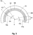
- FIG. 5 is a schematic cross-sectional view of the green tire 1A, taken at the second rubber sheet 12 along the circumferential direction.
- the length L1 in the tire circumferential direction of the overlap portion 12s of the second rubber sheet 12 preferably corresponds to an angle ⁇ 1 of not greater than 30 degrees, more preferably not greater than 27 degrees, and even more preferably not greater than 25 degrees around a center c of rotation of the green tire 1A.
- the length L1 in the circumferential direction of the overlap portion 12s which has a large thickness, is maintained small, and therefore, a poor mass balance of the tire 1 in the circumferential direction is avoided.
- the length L1 in the tire circumferential direction of the overlap portion 12s is small, the second rubber sheet 12 may be separated in the tire circumferential direction. Therefore, the length L1 in the tire circumferential direction of the overlap portion 12s of the second rubber sheet 12 preferably corresponds to an angle ⁇ 1 of not less than 5 degrees, more preferably not less than 7 degrees, and even more preferably not less than 10 degrees around the center c of rotation of the green tire 1A.
- the tire 1 having a poor mass balance has, for example, an adverse influence on ride comfort and running stability.
- the length L2 in the tire circumferential direction of the overlap portion 11s of the first rubber sheet 11 preferably corresponds to an angle ⁇ 2 of not less than 5 degrees, more preferably not less than 7 degrees, and even more preferably not less than 10 degrees around the center c of rotation of the green tire 1A.
- the length L2 in the tire circumferential direction of the overlap portion 11s of the first rubber sheet 11 also preferably corresponds to an angle ⁇ 2 of not greater than 30 degrees, more preferably not greater than 27 degrees, and even more preferably not greater than 25 degrees around the center c of rotation of the green tire 1A.
- the overlap portions 11s and 12s are colored for clarity.
- the overlap portion 12s of the second rubber sheet 12 is preferably located ⁇ 10 degrees away from a light point (not shown) of the green tire 1A in the tire circumferential direction (around the center c of rotation of the green tire 1A). As a result, the mass balance is further improved.
- the "light point” is a position where the green tire 1A has a lightest weight in the circumferential direction.
- FIG. 6 is a cross-sectional view schematically showing the vulcanization step S2.
- a vulcanization mold 32 having a well-known structure and including a bladder 32a is used.
- the green tire 1A is pressed by the bladder 32a from the tire inner cavity side, so that the green tire 1A is vulcanized to form a vulcanized tire 1.
- the tire (shown in FIG. 1 ) 1 including the inner liner 9 having a uniform thickness T is formed.
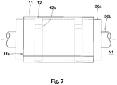
- FIG. 7 is a plan view showing a production method of the first step N1 according to another embodiment.
- the same parts as those of the above embodiment are indicated by the same reference characters and will not be described.
- the first rubber sheet 11 is wrapped on the second rubber sheet 12 wrapped on the wrapping surface 30a and having a smaller width.
- the inner liner 9 after vulcanization can have a uniform thickness T.
- a single rubber sheet (not shown) having a base portion 9a and a pair of thick portions 9b and 9b may be formed by extrusion molding, and may then be wrapped around the forming drum 30, to form the inner liner 9 of the green tire 1A.
- Green tires having the basic structure in FIG. 4 were formed, and vulcanized tires (tires) were produced using the vulcanization device in FIG. 6 . These tires were tested for uniformity, air impermeability, and mass balance. Test methods and common specifications are as follows.
- the thick portion is located outward of the tire maximum width position in the tire radial direction.
- the first rubber sheets have the same width
- the second rubber sheets have the same width
- the thickness of the inner liner was measured using a tester at 50-mm intervals in the tire circumferential direction and in the tire axial direction, and the average deviation thereof was calculated.
- the results are represented by indices with the average deviation of comparative example 1 being regarded as 100. The lower the value, the better the uniformity.
- each of the tires of the examples includes an inner liner having a uniform thickness, and therefore, the tire has excellent air impermeability, and the mass of the tire is maintained small. It can also be confirmed that as the length ( ⁇ 1) of the overlap portion decreases, the uniformity is further improved. In addition, in the tire of Example 4, air remained at the overlap portion, which did not have an adverse influence on the quality of the tire.
Landscapes
- Engineering & Computer Science (AREA)
- Mechanical Engineering (AREA)
- Tyre Moulding (AREA)
Applications Claiming Priority (1)
| Application Number | Priority Date | Filing Date | Title |
|---|---|---|---|
| JP2020008624A JP7424070B2 (ja) | 2020-01-22 | 2020-01-22 | タイヤの製造方法及び生タイヤ |
Publications (2)
| Publication Number | Publication Date |
|---|---|
| EP3854573A1 true EP3854573A1 (fr) | 2021-07-28 |
| EP3854573B1 EP3854573B1 (fr) | 2022-10-26 |
Family
ID=74003996
Family Applications (1)
| Application Number | Title | Priority Date | Filing Date |
|---|---|---|---|
| EP20217498.3A Active EP3854573B1 (fr) | 2020-01-22 | 2020-12-29 | Procédé de production de pneu et pneu cru |
Country Status (3)
| Country | Link |
|---|---|
| EP (1) | EP3854573B1 (fr) |
| JP (1) | JP7424070B2 (fr) |
| CN (1) | CN113146894B (fr) |
Citations (3)
| Publication number | Priority date | Publication date | Assignee | Title |
|---|---|---|---|---|
| JPH0732813A (ja) | 1993-07-21 | 1995-02-03 | Bridgestone Corp | グリーンタイヤ |
| JPH09239861A (ja) * | 1996-03-11 | 1997-09-16 | Yokohama Rubber Co Ltd:The | 空気入りタイヤの製造方法 |
| WO2012106027A1 (fr) * | 2011-02-01 | 2012-08-09 | Exxonmobil Chemical Patents Inc. | Revêtements intérieurs de pneu profilés et leurs procédés de fabrication |
Family Cites Families (18)
| Publication number | Priority date | Publication date | Assignee | Title |
|---|---|---|---|---|
| JPS6382801A (ja) * | 1986-09-26 | 1988-04-13 | Ohtsu Tire & Rubber Co Ltd | 空気入りタイヤ |
| JPH0477243A (ja) * | 1990-07-19 | 1992-03-11 | Bridgestone Corp | 空気入りタイヤ用インナゴム |
| US5824170A (en) * | 1993-09-10 | 1998-10-20 | Michelin Recherche Et Technique S.A. | Tire with a profiled innerliner |
| JP3407959B2 (ja) * | 1993-11-26 | 2003-05-19 | 住友ゴム工業株式会社 | 空気入りタイヤ |
| JP4170821B2 (ja) * | 2003-05-30 | 2008-10-22 | 住友ゴム工業株式会社 | 空気入りラジアルタイヤ |
| US7404424B2 (en) * | 2003-07-17 | 2008-07-29 | The Yokohama Rubber Co., Ltd. | Pneumatic tire with buffer rubber layer |
| JP3716263B2 (ja) * | 2003-11-25 | 2005-11-16 | 横浜ゴム株式会社 | 空気入りラジアルタイヤの製造方法及びそれに用いるベルトトレッド組立体のトランスファー |
| JP2006231564A (ja) * | 2005-02-22 | 2006-09-07 | Bridgestone Corp | 空気入りタイヤの製造方法 |
| JP2007283998A (ja) * | 2006-04-20 | 2007-11-01 | Bridgestone Corp | 空気入りタイヤおよびその製造方法 |
| JP5233261B2 (ja) * | 2007-12-06 | 2013-07-10 | 横浜ゴム株式会社 | 空気入りタイヤ及びその製造方法 |
| JP2009173051A (ja) * | 2008-01-21 | 2009-08-06 | Yokohama Rubber Co Ltd:The | 空気入りタイヤ及びその製造方法 |
| JP5130969B2 (ja) * | 2008-03-17 | 2013-01-30 | 横浜ゴム株式会社 | 空気入りタイヤ用インナーライナー材料の製造方法 |
| JP5308906B2 (ja) * | 2009-04-30 | 2013-10-09 | 株式会社ブリヂストン | タイヤ内面への部材の貼付け方法 |
| WO2012026177A1 (fr) * | 2010-08-25 | 2012-03-01 | 住友ゴム工業株式会社 | Bandage pneumatique et procédé de fabrication de ce dernier, et vessie de vulcanisation de pneu |
| JP5632684B2 (ja) * | 2010-09-03 | 2014-11-26 | 住友ゴム工業株式会社 | 空気入りタイヤおよびその製造方法 |
| JP6199537B2 (ja) * | 2011-12-16 | 2017-09-20 | 住友ゴム工業株式会社 | インナーライナーの製造方法 |
| JP5677384B2 (ja) * | 2012-08-24 | 2015-02-25 | 住友ゴム工業株式会社 | 空気入りタイヤの製造方法、及び空気入りタイヤ |
| JP6862869B2 (ja) * | 2017-01-31 | 2021-04-21 | 横浜ゴム株式会社 | 空気入りタイヤの製造方法および空気入りタイヤ |
-
2020
- 2020-01-22 JP JP2020008624A patent/JP7424070B2/ja active Active
- 2020-12-29 EP EP20217498.3A patent/EP3854573B1/fr active Active
- 2020-12-30 CN CN202011617283.6A patent/CN113146894B/zh active Active
Patent Citations (3)
| Publication number | Priority date | Publication date | Assignee | Title |
|---|---|---|---|---|
| JPH0732813A (ja) | 1993-07-21 | 1995-02-03 | Bridgestone Corp | グリーンタイヤ |
| JPH09239861A (ja) * | 1996-03-11 | 1997-09-16 | Yokohama Rubber Co Ltd:The | 空気入りタイヤの製造方法 |
| WO2012106027A1 (fr) * | 2011-02-01 | 2012-08-09 | Exxonmobil Chemical Patents Inc. | Revêtements intérieurs de pneu profilés et leurs procédés de fabrication |
Also Published As
| Publication number | Publication date |
|---|---|
| CN113146894A (zh) | 2021-07-23 |
| CN113146894B (zh) | 2026-01-23 |
| JP7424070B2 (ja) | 2024-01-30 |
| EP3854573B1 (fr) | 2022-10-26 |
| JP2021115711A (ja) | 2021-08-10 |
Similar Documents
| Publication | Publication Date | Title |
|---|---|---|
| US11173756B2 (en) | Pneumatic tire | |
| JP3391590B2 (ja) | ラジアルタイヤ | |
| EP3845396B1 (fr) | Pneumatique | |
| US20180126802A1 (en) | Pneumatic tire | |
| US11260704B2 (en) | Pneumatic tire | |
| US20200361251A1 (en) | Pneumatic Tire | |
| CN106994865B (zh) | 充气轮胎 | |
| EP3189979B1 (fr) | Pneumatique | |
| US11207929B2 (en) | Pneumatic tire | |
| JP2017121868A (ja) | 空気入りタイヤ | |
| US12122193B2 (en) | Pneumatic tire and method for manufacturing the same | |
| EP0810105B1 (fr) | Bandages pneumatiques radiaux avec une couche renforçant les flancs | |
| JP2016159840A (ja) | 重荷重用空気入りタイヤ及びその製造方法 | |
| EP3854573B1 (fr) | Procédé de production de pneu et pneu cru | |
| EP3943660A1 (fr) | Pneumatique | |
| EP3421262B1 (fr) | Pneu de roulage à plat et son procédé de fabrication | |
| EP3366496B1 (fr) | Pneu de roulage à plat et son procédé de fabrication | |
| EP2865547A1 (fr) | Pneu | |
| US20180244113A1 (en) | Run flat tire and method for manufacturing same | |
| US12005746B2 (en) | Tire, tire mold, and tire production method | |
| US20210379933A1 (en) | Pneumatic tire | |
| AU2017411632A1 (en) | Bias tire | |
| JP5084255B2 (ja) | 空気入りラジアルタイヤの製造方法 | |
| JP3445348B2 (ja) | 空気入りラジアルタイヤ | |
| CN107020889A (zh) | 充气轮胎 |
Legal Events
| Date | Code | Title | Description |
|---|---|---|---|
| PUAI | Public reference made under article 153(3) epc to a published international application that has entered the european phase |
Free format text: ORIGINAL CODE: 0009012 |
|
| STAA | Information on the status of an ep patent application or granted ep patent |
Free format text: STATUS: THE APPLICATION HAS BEEN PUBLISHED |
|
| AK | Designated contracting states |
Kind code of ref document: A1 Designated state(s): AL AT BE BG CH CY CZ DE DK EE ES FI FR GB GR HR HU IE IS IT LI LT LU LV MC MK MT NL NO PL PT RO RS SE SI SK SM TR |
|
| STAA | Information on the status of an ep patent application or granted ep patent |
Free format text: STATUS: REQUEST FOR EXAMINATION WAS MADE |
|
| 17P | Request for examination filed |
Effective date: 20211123 |
|
| RBV | Designated contracting states (corrected) |
Designated state(s): AL AT BE BG CH CY CZ DE DK EE ES FI FR GB GR HR HU IE IS IT LI LT LU LV MC MK MT NL NO PL PT RO RS SE SI SK SM TR |
|
| RIC1 | Information provided on ipc code assigned before grant |
Ipc: B29D 30/08 20060101ALI20220328BHEP Ipc: B29D 30/06 20060101AFI20220328BHEP |
|
| GRAP | Despatch of communication of intention to grant a patent |
Free format text: ORIGINAL CODE: EPIDOSNIGR1 |
|
| STAA | Information on the status of an ep patent application or granted ep patent |
Free format text: STATUS: GRANT OF PATENT IS INTENDED |
|
| INTG | Intention to grant announced |
Effective date: 20220511 |
|
| GRAS | Grant fee paid |
Free format text: ORIGINAL CODE: EPIDOSNIGR3 |
|
| GRAA | (expected) grant |
Free format text: ORIGINAL CODE: 0009210 |
|
| STAA | Information on the status of an ep patent application or granted ep patent |
Free format text: STATUS: THE PATENT HAS BEEN GRANTED |
|
| AK | Designated contracting states |
Kind code of ref document: B1 Designated state(s): AL AT BE BG CH CY CZ DE DK EE ES FI FR GB GR HR HU IE IS IT LI LT LU LV MC MK MT NL NO PL PT RO RS SE SI SK SM TR |
|
| REG | Reference to a national code |
Ref country code: GB Ref legal event code: FG4D |
|
| REG | Reference to a national code |
Ref country code: CH Ref legal event code: EP |
|
| REG | Reference to a national code |
Ref country code: AT Ref legal event code: REF Ref document number: 1526760 Country of ref document: AT Kind code of ref document: T Effective date: 20221115 |
|
| REG | Reference to a national code |
Ref country code: DE Ref legal event code: R096 Ref document number: 602020005895 Country of ref document: DE |
|
| REG | Reference to a national code |
Ref country code: IE Ref legal event code: FG4D |
|
| REG | Reference to a national code |
Ref country code: LT Ref legal event code: MG9D |
|
| REG | Reference to a national code |
Ref country code: NL Ref legal event code: MP Effective date: 20221026 |
|
| REG | Reference to a national code |
Ref country code: AT Ref legal event code: MK05 Ref document number: 1526760 Country of ref document: AT Kind code of ref document: T Effective date: 20221026 |
|
| PG25 | Lapsed in a contracting state [announced via postgrant information from national office to epo] |
Ref country code: NL Free format text: LAPSE BECAUSE OF FAILURE TO SUBMIT A TRANSLATION OF THE DESCRIPTION OR TO PAY THE FEE WITHIN THE PRESCRIBED TIME-LIMIT Effective date: 20221026 |
|
| PG25 | Lapsed in a contracting state [announced via postgrant information from national office to epo] |
Ref country code: SE Free format text: LAPSE BECAUSE OF FAILURE TO SUBMIT A TRANSLATION OF THE DESCRIPTION OR TO PAY THE FEE WITHIN THE PRESCRIBED TIME-LIMIT Effective date: 20221026 Ref country code: PT Free format text: LAPSE BECAUSE OF FAILURE TO SUBMIT A TRANSLATION OF THE DESCRIPTION OR TO PAY THE FEE WITHIN THE PRESCRIBED TIME-LIMIT Effective date: 20230227 Ref country code: NO Free format text: LAPSE BECAUSE OF FAILURE TO SUBMIT A TRANSLATION OF THE DESCRIPTION OR TO PAY THE FEE WITHIN THE PRESCRIBED TIME-LIMIT Effective date: 20230126 Ref country code: LT Free format text: LAPSE BECAUSE OF FAILURE TO SUBMIT A TRANSLATION OF THE DESCRIPTION OR TO PAY THE FEE WITHIN THE PRESCRIBED TIME-LIMIT Effective date: 20221026 Ref country code: FI Free format text: LAPSE BECAUSE OF FAILURE TO SUBMIT A TRANSLATION OF THE DESCRIPTION OR TO PAY THE FEE WITHIN THE PRESCRIBED TIME-LIMIT Effective date: 20221026 Ref country code: ES Free format text: LAPSE BECAUSE OF FAILURE TO SUBMIT A TRANSLATION OF THE DESCRIPTION OR TO PAY THE FEE WITHIN THE PRESCRIBED TIME-LIMIT Effective date: 20221026 Ref country code: AT Free format text: LAPSE BECAUSE OF FAILURE TO SUBMIT A TRANSLATION OF THE DESCRIPTION OR TO PAY THE FEE WITHIN THE PRESCRIBED TIME-LIMIT Effective date: 20221026 |
|
| PG25 | Lapsed in a contracting state [announced via postgrant information from national office to epo] |
Ref country code: RS Free format text: LAPSE BECAUSE OF FAILURE TO SUBMIT A TRANSLATION OF THE DESCRIPTION OR TO PAY THE FEE WITHIN THE PRESCRIBED TIME-LIMIT Effective date: 20221026 Ref country code: PL Free format text: LAPSE BECAUSE OF FAILURE TO SUBMIT A TRANSLATION OF THE DESCRIPTION OR TO PAY THE FEE WITHIN THE PRESCRIBED TIME-LIMIT Effective date: 20221026 Ref country code: LV Free format text: LAPSE BECAUSE OF FAILURE TO SUBMIT A TRANSLATION OF THE DESCRIPTION OR TO PAY THE FEE WITHIN THE PRESCRIBED TIME-LIMIT Effective date: 20221026 Ref country code: IS Free format text: LAPSE BECAUSE OF FAILURE TO SUBMIT A TRANSLATION OF THE DESCRIPTION OR TO PAY THE FEE WITHIN THE PRESCRIBED TIME-LIMIT Effective date: 20230226 Ref country code: HR Free format text: LAPSE BECAUSE OF FAILURE TO SUBMIT A TRANSLATION OF THE DESCRIPTION OR TO PAY THE FEE WITHIN THE PRESCRIBED TIME-LIMIT Effective date: 20221026 Ref country code: GR Free format text: LAPSE BECAUSE OF FAILURE TO SUBMIT A TRANSLATION OF THE DESCRIPTION OR TO PAY THE FEE WITHIN THE PRESCRIBED TIME-LIMIT Effective date: 20230127 |
|
| P01 | Opt-out of the competence of the unified patent court (upc) registered |
Effective date: 20230510 |
|
| REG | Reference to a national code |
Ref country code: DE Ref legal event code: R097 Ref document number: 602020005895 Country of ref document: DE |
|
| PG25 | Lapsed in a contracting state [announced via postgrant information from national office to epo] |
Ref country code: SM Free format text: LAPSE BECAUSE OF FAILURE TO SUBMIT A TRANSLATION OF THE DESCRIPTION OR TO PAY THE FEE WITHIN THE PRESCRIBED TIME-LIMIT Effective date: 20221026 Ref country code: RO Free format text: LAPSE BECAUSE OF FAILURE TO SUBMIT A TRANSLATION OF THE DESCRIPTION OR TO PAY THE FEE WITHIN THE PRESCRIBED TIME-LIMIT Effective date: 20221026 Ref country code: EE Free format text: LAPSE BECAUSE OF FAILURE TO SUBMIT A TRANSLATION OF THE DESCRIPTION OR TO PAY THE FEE WITHIN THE PRESCRIBED TIME-LIMIT Effective date: 20221026 Ref country code: DK Free format text: LAPSE BECAUSE OF FAILURE TO SUBMIT A TRANSLATION OF THE DESCRIPTION OR TO PAY THE FEE WITHIN THE PRESCRIBED TIME-LIMIT Effective date: 20221026 Ref country code: CZ Free format text: LAPSE BECAUSE OF FAILURE TO SUBMIT A TRANSLATION OF THE DESCRIPTION OR TO PAY THE FEE WITHIN THE PRESCRIBED TIME-LIMIT Effective date: 20221026 |
|
| REG | Reference to a national code |
Ref country code: BE Ref legal event code: MM Effective date: 20221231 |
|
| PG25 | Lapsed in a contracting state [announced via postgrant information from national office to epo] |
Ref country code: SK Free format text: LAPSE BECAUSE OF FAILURE TO SUBMIT A TRANSLATION OF THE DESCRIPTION OR TO PAY THE FEE WITHIN THE PRESCRIBED TIME-LIMIT Effective date: 20221026 Ref country code: LU Free format text: LAPSE BECAUSE OF NON-PAYMENT OF DUE FEES Effective date: 20221229 Ref country code: AL Free format text: LAPSE BECAUSE OF FAILURE TO SUBMIT A TRANSLATION OF THE DESCRIPTION OR TO PAY THE FEE WITHIN THE PRESCRIBED TIME-LIMIT Effective date: 20221026 |
|
| PLBE | No opposition filed within time limit |
Free format text: ORIGINAL CODE: 0009261 |
|
| STAA | Information on the status of an ep patent application or granted ep patent |
Free format text: STATUS: NO OPPOSITION FILED WITHIN TIME LIMIT |
|
| 26N | No opposition filed |
Effective date: 20230727 |
|
| PG25 | Lapsed in a contracting state [announced via postgrant information from national office to epo] |
Ref country code: IE Free format text: LAPSE BECAUSE OF NON-PAYMENT OF DUE FEES Effective date: 20221229 |
|
| PG25 | Lapsed in a contracting state [announced via postgrant information from national office to epo] |
Ref country code: SI Free format text: LAPSE BECAUSE OF FAILURE TO SUBMIT A TRANSLATION OF THE DESCRIPTION OR TO PAY THE FEE WITHIN THE PRESCRIBED TIME-LIMIT Effective date: 20221026 Ref country code: BE Free format text: LAPSE BECAUSE OF NON-PAYMENT OF DUE FEES Effective date: 20221231 |
|
| PG25 | Lapsed in a contracting state [announced via postgrant information from national office to epo] |
Ref country code: CY Free format text: LAPSE BECAUSE OF FAILURE TO SUBMIT A TRANSLATION OF THE DESCRIPTION OR TO PAY THE FEE WITHIN THE PRESCRIBED TIME-LIMIT Effective date: 20221026 |
|
| PG25 | Lapsed in a contracting state [announced via postgrant information from national office to epo] |
Ref country code: MK Free format text: LAPSE BECAUSE OF FAILURE TO SUBMIT A TRANSLATION OF THE DESCRIPTION OR TO PAY THE FEE WITHIN THE PRESCRIBED TIME-LIMIT Effective date: 20221026 Ref country code: IT Free format text: LAPSE BECAUSE OF FAILURE TO SUBMIT A TRANSLATION OF THE DESCRIPTION OR TO PAY THE FEE WITHIN THE PRESCRIBED TIME-LIMIT Effective date: 20221026 |
|
| PG25 | Lapsed in a contracting state [announced via postgrant information from national office to epo] |
Ref country code: MC Free format text: LAPSE BECAUSE OF FAILURE TO SUBMIT A TRANSLATION OF THE DESCRIPTION OR TO PAY THE FEE WITHIN THE PRESCRIBED TIME-LIMIT Effective date: 20221026 |
|
| PG25 | Lapsed in a contracting state [announced via postgrant information from national office to epo] |
Ref country code: MC Free format text: LAPSE BECAUSE OF FAILURE TO SUBMIT A TRANSLATION OF THE DESCRIPTION OR TO PAY THE FEE WITHIN THE PRESCRIBED TIME-LIMIT Effective date: 20221026 |
|
| PG25 | Lapsed in a contracting state [announced via postgrant information from national office to epo] |
Ref country code: BG Free format text: LAPSE BECAUSE OF FAILURE TO SUBMIT A TRANSLATION OF THE DESCRIPTION OR TO PAY THE FEE WITHIN THE PRESCRIBED TIME-LIMIT Effective date: 20221026 |
|
| REG | Reference to a national code |
Ref country code: CH Ref legal event code: PL |
|
| PG25 | Lapsed in a contracting state [announced via postgrant information from national office to epo] |
Ref country code: MT Free format text: LAPSE BECAUSE OF FAILURE TO SUBMIT A TRANSLATION OF THE DESCRIPTION OR TO PAY THE FEE WITHIN THE PRESCRIBED TIME-LIMIT Effective date: 20221026 |
|
| PG25 | Lapsed in a contracting state [announced via postgrant information from national office to epo] |
Ref country code: CH Free format text: LAPSE BECAUSE OF NON-PAYMENT OF DUE FEES Effective date: 20231231 |
|
| PG25 | Lapsed in a contracting state [announced via postgrant information from national office to epo] |
Ref country code: CH Free format text: LAPSE BECAUSE OF NON-PAYMENT OF DUE FEES Effective date: 20231231 |
|
| PG25 | Lapsed in a contracting state [announced via postgrant information from national office to epo] |
Ref country code: HU Free format text: LAPSE BECAUSE OF FAILURE TO SUBMIT A TRANSLATION OF THE DESCRIPTION OR TO PAY THE FEE WITHIN THE PRESCRIBED TIME-LIMIT; INVALID AB INITIO Effective date: 20201229 |
|
| GBPC | Gb: european patent ceased through non-payment of renewal fee |
Effective date: 20241229 |
|
| PG25 | Lapsed in a contracting state [announced via postgrant information from national office to epo] |
Ref country code: GB Free format text: LAPSE BECAUSE OF NON-PAYMENT OF DUE FEES Effective date: 20241229 |
|
| PG25 | Lapsed in a contracting state [announced via postgrant information from national office to epo] |
Ref country code: TR Free format text: LAPSE BECAUSE OF FAILURE TO SUBMIT A TRANSLATION OF THE DESCRIPTION OR TO PAY THE FEE WITHIN THE PRESCRIBED TIME-LIMIT Effective date: 20221026 |
|
| PGFP | Annual fee paid to national office [announced via postgrant information from national office to epo] |
Ref country code: DE Payment date: 20251104 Year of fee payment: 6 |
|
| PGFP | Annual fee paid to national office [announced via postgrant information from national office to epo] |
Ref country code: FR Payment date: 20251110 Year of fee payment: 6 |