EP3854629B1 - Système et procédé de détection et d'avertissement de vol et de vandalisme pour colonnes de charge pour véhicules - Google Patents
Système et procédé de détection et d'avertissement de vol et de vandalisme pour colonnes de charge pour véhicules Download PDFInfo
- Publication number
- EP3854629B1 EP3854629B1 EP20153013.6A EP20153013A EP3854629B1 EP 3854629 B1 EP3854629 B1 EP 3854629B1 EP 20153013 A EP20153013 A EP 20153013A EP 3854629 B1 EP3854629 B1 EP 3854629B1
- Authority
- EP
- European Patent Office
- Prior art keywords
- sensor
- charging station
- computing unit
- activated
- control
- Prior art date
- Legal status (The legal status is an assumption and is not a legal conclusion. Google has not performed a legal analysis and makes no representation as to the accuracy of the status listed.)
- Active
Links
Images


Classifications
-
- G—PHYSICS
- G08—SIGNALLING
- G08B—SIGNALLING SYSTEMS, e.g. PERSONAL CALLING SYSTEMS; ORDER TELEGRAPHS; ALARM SYSTEMS
- G08B13/00—Burglar, theft or intruder alarms
- G08B13/22—Electrical actuation
-
- B—PERFORMING OPERATIONS; TRANSPORTING
- B60—VEHICLES IN GENERAL
- B60L—PROPULSION OF ELECTRICALLY-PROPELLED VEHICLES; SUPPLYING ELECTRIC POWER FOR AUXILIARY EQUIPMENT OF ELECTRICALLY-PROPELLED VEHICLES; ELECTRODYNAMIC BRAKE SYSTEMS FOR VEHICLES IN GENERAL; MAGNETIC SUSPENSION OR LEVITATION FOR VEHICLES; MONITORING OPERATING VARIABLES OF ELECTRICALLY-PROPELLED VEHICLES; ELECTRIC SAFETY DEVICES FOR ELECTRICALLY-PROPELLED VEHICLES
- B60L53/00—Methods of charging batteries, specially adapted for electric vehicles; Charging stations or on-board charging equipment therefor; Exchange of energy storage elements in electric vehicles
- B60L53/30—Constructional details of charging stations
- B60L53/305—Communication interfaces
-
- B—PERFORMING OPERATIONS; TRANSPORTING
- B60—VEHICLES IN GENERAL
- B60L—PROPULSION OF ELECTRICALLY-PROPELLED VEHICLES; SUPPLYING ELECTRIC POWER FOR AUXILIARY EQUIPMENT OF ELECTRICALLY-PROPELLED VEHICLES; ELECTRODYNAMIC BRAKE SYSTEMS FOR VEHICLES IN GENERAL; MAGNETIC SUSPENSION OR LEVITATION FOR VEHICLES; MONITORING OPERATING VARIABLES OF ELECTRICALLY-PROPELLED VEHICLES; ELECTRIC SAFETY DEVICES FOR ELECTRICALLY-PROPELLED VEHICLES
- B60L53/00—Methods of charging batteries, specially adapted for electric vehicles; Charging stations or on-board charging equipment therefor; Exchange of energy storage elements in electric vehicles
- B60L53/30—Constructional details of charging stations
- B60L53/31—Charging columns specially adapted for electric vehicles
-
- G—PHYSICS
- G08—SIGNALLING
- G08B—SIGNALLING SYSTEMS, e.g. PERSONAL CALLING SYSTEMS; ORDER TELEGRAPHS; ALARM SYSTEMS
- G08B13/00—Burglar, theft or intruder alarms
- G08B13/02—Mechanical actuation
- G08B13/14—Mechanical actuation by lifting or attempted removal of hand-portable articles
- G08B13/1436—Mechanical actuation by lifting or attempted removal of hand-portable articles with motion detection
-
- G—PHYSICS
- G08—SIGNALLING
- G08B—SIGNALLING SYSTEMS, e.g. PERSONAL CALLING SYSTEMS; ORDER TELEGRAPHS; ALARM SYSTEMS
- G08B13/00—Burglar, theft or intruder alarms
- G08B13/18—Actuation by interference with heat, light, or radiation of shorter wavelength; Actuation by intruding sources of heat, light, or radiation of shorter wavelength
- G08B13/189—Actuation by interference with heat, light, or radiation of shorter wavelength; Actuation by intruding sources of heat, light, or radiation of shorter wavelength using passive radiation detection systems
- G08B13/194—Actuation by interference with heat, light, or radiation of shorter wavelength; Actuation by intruding sources of heat, light, or radiation of shorter wavelength using passive radiation detection systems using image scanning and comparing systems
- G08B13/196—Actuation by interference with heat, light, or radiation of shorter wavelength; Actuation by intruding sources of heat, light, or radiation of shorter wavelength using passive radiation detection systems using image scanning and comparing systems using television cameras
- G08B13/19695—Arrangements wherein non-video detectors start video recording or forwarding but do not generate an alarm themselves
-
- G—PHYSICS
- G08—SIGNALLING
- G08B—SIGNALLING SYSTEMS, e.g. PERSONAL CALLING SYSTEMS; ORDER TELEGRAPHS; ALARM SYSTEMS
- G08B25/00—Alarm systems in which the location of the alarm condition is signalled to a central station, e.g. fire or police telegraphic systems
- G08B25/01—Alarm systems in which the location of the alarm condition is signalled to a central station, e.g. fire or police telegraphic systems characterised by the transmission medium
- G08B25/10—Alarm systems in which the location of the alarm condition is signalled to a central station, e.g. fire or police telegraphic systems characterised by the transmission medium using wireless transmission systems
-
- G—PHYSICS
- G08—SIGNALLING
- G08B—SIGNALLING SYSTEMS, e.g. PERSONAL CALLING SYSTEMS; ORDER TELEGRAPHS; ALARM SYSTEMS
- G08B29/00—Checking or monitoring of signalling or alarm systems; Prevention or correction of operating errors, e.g. preventing unauthorised operation
- G08B29/18—Prevention or correction of operating errors
- G08B29/185—Signal analysis techniques for reducing or preventing false alarms or for enhancing the reliability of the system
- G08B29/188—Data fusion; cooperative systems, e.g. voting among different detectors
-
- B—PERFORMING OPERATIONS; TRANSPORTING
- B60—VEHICLES IN GENERAL
- B60L—PROPULSION OF ELECTRICALLY-PROPELLED VEHICLES; SUPPLYING ELECTRIC POWER FOR AUXILIARY EQUIPMENT OF ELECTRICALLY-PROPELLED VEHICLES; ELECTRODYNAMIC BRAKE SYSTEMS FOR VEHICLES IN GENERAL; MAGNETIC SUSPENSION OR LEVITATION FOR VEHICLES; MONITORING OPERATING VARIABLES OF ELECTRICALLY-PROPELLED VEHICLES; ELECTRIC SAFETY DEVICES FOR ELECTRICALLY-PROPELLED VEHICLES
- B60L2270/00—Problem solutions or means not otherwise provided for
- B60L2270/30—Preventing theft during charging
- B60L2270/34—Preventing theft during charging of parts
-
- Y—GENERAL TAGGING OF NEW TECHNOLOGICAL DEVELOPMENTS; GENERAL TAGGING OF CROSS-SECTIONAL TECHNOLOGIES SPANNING OVER SEVERAL SECTIONS OF THE IPC; TECHNICAL SUBJECTS COVERED BY FORMER USPC CROSS-REFERENCE ART COLLECTIONS [XRACs] AND DIGESTS
- Y02—TECHNOLOGIES OR APPLICATIONS FOR MITIGATION OR ADAPTATION AGAINST CLIMATE CHANGE
- Y02T—CLIMATE CHANGE MITIGATION TECHNOLOGIES RELATED TO TRANSPORTATION
- Y02T10/00—Road transport of goods or passengers
- Y02T10/60—Other road transportation technologies with climate change mitigation effect
- Y02T10/70—Energy storage systems for electromobility, e.g. batteries
-
- Y—GENERAL TAGGING OF NEW TECHNOLOGICAL DEVELOPMENTS; GENERAL TAGGING OF CROSS-SECTIONAL TECHNOLOGIES SPANNING OVER SEVERAL SECTIONS OF THE IPC; TECHNICAL SUBJECTS COVERED BY FORMER USPC CROSS-REFERENCE ART COLLECTIONS [XRACs] AND DIGESTS
- Y02—TECHNOLOGIES OR APPLICATIONS FOR MITIGATION OR ADAPTATION AGAINST CLIMATE CHANGE
- Y02T—CLIMATE CHANGE MITIGATION TECHNOLOGIES RELATED TO TRANSPORTATION
- Y02T10/00—Road transport of goods or passengers
- Y02T10/60—Other road transportation technologies with climate change mitigation effect
- Y02T10/7072—Electromobility specific charging systems or methods for batteries, ultracapacitors, supercapacitors or double-layer capacitors
-
- Y—GENERAL TAGGING OF NEW TECHNOLOGICAL DEVELOPMENTS; GENERAL TAGGING OF CROSS-SECTIONAL TECHNOLOGIES SPANNING OVER SEVERAL SECTIONS OF THE IPC; TECHNICAL SUBJECTS COVERED BY FORMER USPC CROSS-REFERENCE ART COLLECTIONS [XRACs] AND DIGESTS
- Y02—TECHNOLOGIES OR APPLICATIONS FOR MITIGATION OR ADAPTATION AGAINST CLIMATE CHANGE
- Y02T—CLIMATE CHANGE MITIGATION TECHNOLOGIES RELATED TO TRANSPORTATION
- Y02T90/00—Enabling technologies or technologies with a potential or indirect contribution to GHG emissions mitigation
- Y02T90/10—Technologies relating to charging of electric vehicles
- Y02T90/12—Electric charging stations
-
- Y—GENERAL TAGGING OF NEW TECHNOLOGICAL DEVELOPMENTS; GENERAL TAGGING OF CROSS-SECTIONAL TECHNOLOGIES SPANNING OVER SEVERAL SECTIONS OF THE IPC; TECHNICAL SUBJECTS COVERED BY FORMER USPC CROSS-REFERENCE ART COLLECTIONS [XRACs] AND DIGESTS
- Y02—TECHNOLOGIES OR APPLICATIONS FOR MITIGATION OR ADAPTATION AGAINST CLIMATE CHANGE
- Y02T—CLIMATE CHANGE MITIGATION TECHNOLOGIES RELATED TO TRANSPORTATION
- Y02T90/00—Enabling technologies or technologies with a potential or indirect contribution to GHG emissions mitigation
- Y02T90/10—Technologies relating to charging of electric vehicles
- Y02T90/16—Information or communication technologies improving the operation of electric vehicles
Definitions
- the invention relates to a charging station for charging vehicles and comprising a system for theft and vandalism detection and for warning in the event of theft and vandalism detection.
- the invention further relates to a method for such a charging station for theft and vandalism detection and for warning in the event of theft and vandalism detection, as well as a computer program product.
- a device and a method for monitoring a charging cable for a vehicle are known.
- a device for monitoring a charging cable for a vehicle comprising a device for detecting the vehicle's surroundings, at least in the region of the charging cable, wherein connecting the charging cable to the vehicle activates the detection of the vehicle's surroundings.
- a warning signal for a charging station is known.
- a method for providing a warning signal for a charging station to warn of damage to the charging station is presented.
- a charging station for this purpose is also presented.
- a classification result is determined, and a warning signal is issued based on this result.
- a device for charging an electrochemical traction energy storage device of a means of transport comprises the following components: an electrochemical energy storage device for charging the traction energy storage device of the means of transport, a charging plug for establishing an electrical connection to the traction energy storage device of the means of transport, an evaluation unit, a transmitting device, and a locating module, wherein the locating module is configured to determine a position of the device and to transmit it to a central management facility by means of the transmitting device.
- DE 10 2013 206 687 A1 discloses a method for providing a warning signal for a charging station to warn of damage to the charging station.
- a sensor element such as a position sensor or a motion sensor, is activated.
- a warning signal is triggered based on the signal then present.
- CN 206 863 882 U discloses an anti-theft device for a charging station.
- the charging station has a vibration sensor for this purpose. When the vibration sensor is activated, a connection is established to a remotely located monitoring terminal.
- US 2018 / 357 871 A1 reveals an audio/video intercom for buildings.
- a motion sensor activates a camera to detect who is in the intercom area via a remote monitor.
- the invention is based on the object of providing a charging station for charging vehicles with an alternative system for theft and vandalism detection and for warning in the event of theft and vandalism detection, which ensures a needs-based and reliable operation.
- a charging station for charging vehicles is provided with a system for theft and vandalism detection and warning according to claim 1.
- a system comprises a control and computing unit with an evaluation program and a plurality of different sensor elements designed to detect states of the charging station. At least one unit of each different sensor element is provided. The respective sensor elements are each coupled to the control and computing unit with the evaluation program, so that respective states of the sensor elements can be detected and/or controlled.
- a system comprises at least one actuator element for outputting a warning signal.
- At least one inclination sensor and at least one motion sensor are activated, wherein a respective change in the state of the at least one inclination sensor and/or the at least one motion sensor detected by the control and computing unit with evaluation program triggers the activation of at least one further sensor element, so that an evaluation of all activated sensor elements can be carried out by the control and computing unit with evaluation program and, depending on the evaluation result, a dedicated action routine stored in the evaluation program can be triggered.
- a dedicated action routine stored in the evaluation program can be triggered.
- the mode of operation is staggered, with four stages being provided, for example.
- the at least one inclination sensor and/or the at least one motion sensor play a central role.
- These sensors are provided for environmental detection, and only in response to a respective change in the state of these sensors are further elements activated, whereby, for example, mechanical influences on the charging station are checked and a more detailed environmental detection can be carried out.
- the further steps are then at least partially integrated into the respectively triggered action routine.
- the action routine is designed, for example, to at least counteract attempts at theft and/or vandalism or to provide actions that are suitable for proactively counteracting external influences or at least for appropriately documenting and/or measuring them.
- This division enables energy-saving operation and Demand-based activation of the monitoring functions of the system provided by the respective sensor elements. This allows the system to also meet country-specific data protection requirements, as there is no permanent monitoring, but rather only needs-based, event-driven, more intensive monitoring. This also leads to an increase in the service life of individual components, as continuous operation is avoided.
- the activated system in the first stage, is in a type of normal operation, in that only the at least one inclination sensor and/or the at least one motion sensor are activated, so that, for example, the approach of a person or an object can be reliably detected.
- the second stage is initiated with activation of the additional sensor elements.
- the system is thus advantageously designed to be integrated into a charging station, ensuring the integration of a multi-stage sensor system into the charging station to detect improper handling (theft, vandalism) as well as environmental influences.
- a method for theft and vandalism detection and warning for charging stations for vehicles comprises, among other things, the following steps: providing a control and computing unit with an evaluation program, providing a plurality of different sensor elements which are designed to detect states of the charging station, wherein at least one unit of each different sensor element is provided and respective sensor elements are each coupled to the control and computing unit with an evaluation program so that respective states of the sensor elements can be detected and/or controlled, providing at least one actuator element for outputting a warning signal.
- the method also comprises, among other things, the following further step: activating at least one inclination sensor and at least one motion sensor, wherein a respective change in state of the at least one inclination sensor and/or the at least one motion sensor detected by the control and computing unit with evaluation program causes an activation of at least one further sensor element, so that an evaluation of all activated sensor elements can be carried out by means of the control and computing unit with evaluation program and, depending on an evaluation result, an action routine provided for this purpose and stored in the evaluation program can be triggered.
- Such a charging station is preferably equipped with at least one permanently installed battery to offer higher charging capacities and operate independently of the corresponding infrastructure. This further increases the value of such a charging station. Due to the electrical independence from the infrastructure, there is no longer any need for permanently mounted charging stations. The aforementioned advantages also apply, to the extent applicable, to the charging station presented here.
- the at least one further sensor element is selected from: acceleration sensor, shock sensor, brightness sensor, and preferably further from camera device and microphone device.
- the action routine comprises an activation of the at least one actuator element and a deactivation of a power electronics of the charging station.
- a respective action routine which activates the at least one provided actuator element.
- an integration of a multi-stage actuator system can be provided which is designed to actively display and play back warning messages in the event of improper handling (theft, vandalism) of the charging station.
- an automatic shutdown of the power electronics as needed to protect people.
- the charging station can therefore also rendered unusable, so that theft is no longer worthwhile.
- this deactivation and unusable mode can be restricted to a group of people without access authorization.
- the at least one actuator element is selected from: a loudspeaker, a screen unit, an exterior lighting element, a tilt compensation device, in particular a tilt compensation device with at least one servomotor, or a warning light element.
- a further embodiment of the invention provides for a user-defined functional test of the system after the power electronics of the charging station have been switched off.
- This functional test is intended, in particular, as a type of self-test. When a user triggers this test, the system is thus able to perform the following steps and actions automatically.
- the integrated intelligent functional test ensures the functional safety of the charging station on-site with the highest possible availability.
- a further embodiment of the invention also provides for the functional test to include a respective test routine for the various, differing sensor elements. This allows for verification of the extent to which triggered actions in the system may or may not be related to a damaged or faulty sensor element. This test routine thus ensures a particularly reliable system.
- a further embodiment of the invention provides that the functional test includes a respective test routine for the at least one actuator element.
- the functional test includes a respective test routine for the at least one actuator element.
- a further embodiment of the invention provides for the respective test results of the individual test routines to be evaluated together using the control and processing unit with the evaluation program, so that multiple errors can be detected.
- Mutually dependent error sources can thus be clearly identified, allowing appropriate courses of action to be initiated quickly.
- the respective test routines for the various, differing sensor elements are designed to compare the respective measured current values of the respective, differing sensor elements with the respective expected values stored in the control and computing unit with the evaluation program, so that the extent of an error can be determined and, depending on this extent, at least one further action routine stored in the evaluation program can be triggered. This ensures particularly reliable operation of the system, since the functionality of the individual, differing sensor elements can be checked during operation, so that any false alarms can be detected.
- a further action routine comprises the activation of a position-finding device. If the charging station and thus the integrated system are moved spatially away from a destination, this movement can not only be registered, but a new position can also be determined quickly and reliably using the position-finding device. This makes it easy to locate a stolen charging station and secure it accordingly.
- a position-finding device can, for example, comprise a suitable GPS receiver, which can be integrated, for example, in a roof of the system or the charging station. The integration of such a GPS receiver serves to determine the current position and any change in position, which is of particular interest, for example, in the event of a theft attempt.
- a further action routine comprises activating a communication unit, in particular a communication unit based on mobile radio and/or Wi-Fi technology, so that at least information about the current status of the charging station can be provided to an operator.
- a communication unit in particular a communication unit based on mobile radio and/or Wi-Fi technology
- a further embodiment of the invention provides that, prior to each activation of the system, a user-defined start routine can be executed, which includes a respective test routine for the various sensor elements and/or an insulation test of the power electronics of the charging station and/or a battery test.
- This start routine thus ensures reliable operation in such a way that so that false alarms during ongoing operations can be essentially ruled out.
- Figure 1 shows a schematic representation of a system 10 for theft and vandalism detection and warning for charging stations 28 for vehicles.
- the system 10 is shown with a control and computing unit 12 with an evaluation program 14.
- the evaluation program 14 is designed, for example, to include a computer program product for carrying out a method according to claim 12.
- this evaluation program 14 is also intended to assume and execute controlling activities of the system 10 and its respective components.
- the system 10 is shown with an inclination sensor 16 and a motion sensor 18, each of which is coupled to the control and computing unit 12 with the evaluation program 14, so that the respective states of these sensor elements 16, 18 can be detected and/or controlled.
- the system 10 is shown with an actuator element 20 for outputting a warning signal and further sensor elements 22, 24, 26, these elements also being coupled to the control and computing unit 12 with the evaluation program 14.
- the different sensor elements 16, 18, 22, 24, 26 are designed to detect states of a charging station 28 (not shown in detail).
- the different sensor elements 16, 18, 22, 24, 26 are each designed such that a different state can be detected.
- the inclination sensor 16 is therefore designed to detect movement states of the system 10 or of a charging station 28 (not shown in detail). These movement states can relate, for example, to heights, depths, and inclinations. For example, changes in the ground, in particular tipping and/or sinking, but also an attempt to transport, can thus be detected.
- the motion sensor 18, detects the extent to which at least one person or at least one object approaches the system 10 or a charging station 28 into which the system 10 is integrated. This motion sensor 18 can, for example, be arranged on the outside of the system 10.
- the inclination sensor 16 and the motion sensor 18 are activated, wherein each change in the state of the inclination sensor 16 and/or the motion sensor 18 detected by the control and computing unit 12 with evaluation program 14 causes an activation of at least one further sensor element 22, 24, 26, so that an evaluation of all activated sensor elements 16, 18, 22, 24, 26 can be carried out by the control and computing unit 12 with evaluation program 14 and, depending on an evaluation result, an action routine provided for this purpose and stored in the evaluation program 14 can be triggered.
- the first further sensor element 22 can be or comprise an acceleration sensor, for example.
- the second further sensor element 24 can be or comprise a brightness sensor, for example.
- the third further sensor element 26 can be or comprise a shock sensor, for example.
- the shock sensor can, for example, be integrated into an exterior wall of the system 10 so that mechanical impacts on the exterior wall or outer skin can be reliably detected.
- the brightness sensor can, for example, be integrated into an exterior wall of the system 10 so that, for example, dirt, both natural and in the form of graffiti, on the exterior wall or outer skin can be reliably detected.
- the actuator element 20 may, for example, be selected from the following components: loudspeaker, screen unit, exterior lighting element, inclination compensation device, in particular an inclination compensation device with at least one servo motor, warning light element.
- loudspeaker may, for example, be provided for acoustic warning notification when one of the aforementioned sensor elements 16, 18, 22, 24, 26 is activated.
- a warning signal can thus be emitted.
- This warning signal may be provided in the form of an audio signal and/or in the form of a warning message.
- This warning signal can also be provided specifically for the respective activated sensor element 16, 18, 22, 24, 26 or correspond to a combination of activated sensor elements 16, 18, 22, 24, 26 or can be stored in the system 10 in a user-defined manner.
- the integration of one or more display units and/or one or more warning lights and/or an exterior lighting element can be provided, for example, as a visual warning signal or as a visual warning message.
- This visual warning signal can also be provided specifically for the respective activated sensor element 16, 18, 22, 24, 26 or correspond to a combination of activated sensor elements 16, 18, 22, 24, 26 or can be stored in the system 10 in a user-defined manner.
- the inclination compensation device can, for example, be provided with at least one servomotor at the lower corners of the system 10 or the charging station 28 into which the system 10 is to be integrated, in order to be able to detect and/or compensate for unevenness and changes in the ground.
- the integration of cameras can, for example, be provided to detect and record the direct surroundings of the system 10 or the charging station 28 into which the system 10 is to be integrated.
- the integration of microphones can also be provided to acoustically detect and record this surroundings.
- the integration of a multi-stage actuator system can be provided for the active display and playback of warning signals and/or warning messages in the event of improper handling (theft, vandalism) and environmental influences.
- a needs-based activation of face, object, and voice recognition for rapid, automated evaluation of the situation can be provided.
- the number of Any number of different sensor elements 16, 18, 22, 24, 26 can be provided. For example, this number can be provided depending on the size of the charging station into which the presented system 10 is to be integrated. This number of different sensor elements 16, 18, 22, 24, 26 can be distributed in such a way that the previously explained advantages can be optimally provided in each case.
- Figure 2 shows a method flow diagram 100 of a method for theft and vandalism detection and warning for charging stations 28 for vehicles.
- a control and computing unit 12 with an evaluation program 14 is provided in a first method step 110.
- a plurality of different sensor elements 16, 18, 22, 24, 26 are provided, which are designed to detect states of the charging station 28, wherein at least one unit of each different sensor element 16, 18, 22, 24, 26 is provided and respective sensor elements 16, 18, 22, 24, 26 are each coupled to the control and computing unit 12 with the evaluation program 14, so that respective states of the sensor elements 16, 18, 22, 24, 26 can be detected and/or controlled.
- at least one actuator element 20 is provided for outputting a warning signal.
- a fourth method step 140 at least one inclination sensor 16 and at least one motion sensor 18 are provided, wherein a respective change in state of the at least one inclination sensor 16 and/or the at least one motion sensor 18 detected by the control and computing unit 12 with evaluation program 14 causes an activation of at least one further sensor element 22, 24, 26, so that an evaluation of all activated sensor elements 16, 18, 22, 24, 26 can be carried out by the control and computing unit 12 with evaluation program 14 and, depending on an evaluation result, an action routine provided for this purpose and stored in the evaluation program 14 can be triggered.
- FIG. 3 shows a more detailed further process flow diagram 200 of a method for theft and vandalism detection and warning for charging stations 28 for vehicles.
- This more detailed further process flow diagram 200 is shown divided into four stages 210, 220, 230, 240, with the successive stages 210, 220, 230, 240 being shown from left to right in relation to the image plane.
- an environment detection takes place.
- a mechanical impact is detected.
- a more detailed environment detection and person identification take place.
- position tracking takes place.
- a first procedural action 250 an operator starts a system 10 for theft and vandalism detection and warning for charging stations 28 for vehicles.
- This system 10 is provided as functionally integrated into the charging station 28.
- a second procedural action 252 an inclination sensor 16 and a motion sensor 18 are activated.
- the inclination sensor 16 and the motion sensor 18 are monitored by a control and computing unit 12 with an evaluation program 14.
- a query is made as to the extent to which movement of the system 10 or the charging station 28 in which the system 10 is integrated is detected. If no, further monitoring takes place. If yes, a fifth procedural action 258 follows, in which lighting, for example, an exterior lighting element, is activated.
- an acoustic and/or optical detector is also activated.
- a seventh procedural action 262 can query whether an inclination was detected during monitoring of the inclination sensor 16. If not, further monitoring is performed. If yes, an eighth procedural action 264 queries the extent to which the detected inclination is greater than a predetermined value x. If the detected inclination is not greater than a predetermined value x, an inclination compensation is activated in a ninth procedural action 266, and further monitoring of the inclination sensor 16 follows. If the detected inclination is greater than a predetermined value x, a communication of the sensor value is sent to the operator in a tenth procedural action 268.
- an acceleration sensor 270 is activated and/or in a twelfth method step 272
- a shock sensor is activated and/or in a thirteenth method step 274, a brightness sensor is activated.
- a fourteenth procedural action 276 the individual sensor elements are queried, whereby these sensor values are provided to the control and processing unit 12 with the evaluation program 14.
- a fifteenth procedural action 278 the sensor values are evaluated. If at least one sensor value is outside a threshold value, which is queried in a sixteenth procedural action 280, the tenth procedural action 268 also follows, namely, communication is established and the sensor value is sent to the operator. If this is not the case, the system switches back to the fourteenth procedural action 276.
- a local warning device is activated in a seventeenth procedural action 282, and the power electronics of the charging station 28 are switched off. This is verified by the operator in an eighteenth procedural action 284. The operator's results are checked in a nineteenth procedural action 286. If this results check reveals that the transmitted values are not correct, all customer functions associated with the system 10 and the charging station 28, into which the system 10 is integrated, are deactivated in a twentieth procedural action. If, however, everything is OK, the process switches accordingly to the first procedural action 250, so that the previously explained actions begin again from the beginning.
- the third and fourth stages 230, 240 are activated in parallel. This process is optional, since further actions are provided in these two stages 230, 240.
- a query is made as to whether an acceleration detected by the acceleration sensor lies outside a specified threshold value. If not, a camera device is activated in a twenty-second procedural action 292 and/or a microphone device is activated in a twenty-third procedural action 294.
- the sensor elements are queried, whereby these sensor values are also provided to the control and processing unit 12 with the evaluation program 14.
- this control and processing unit 12 with the evaluation program 14 is shown in this Figure 3 shown twice, but in each case the same control and computing unit 12 with evaluation program 14 is used.
- this control and computing unit can also be merely a buffer or a buffer with at least one additional function.
- two separate structural units can thus also be provided, each comprising at least one storage function and/or a functionally expanded storage component.
- the sensor values are temporarily stored here for evaluation at a later time.
- the camera data is evaluated, for example, facial recognition and/or object recognition takes place.
- a twenty-sixth procedural action 300 the microphone data is evaluated, for example, voice recognition is performed.
- the camera and microphone recordings are sent to the operator, while at the same time, in a twenty-eighth procedural action 304, a query is made again as to whether a detected acceleration lies outside a specified threshold value. If If no, the program continues with the twenty-first procedural action 290.
- a positioning device for example in the form of a GPS device, is activated in a twenty-ninth procedural action 306, whereby the twenty-second procedural action 292 is also triggered simultaneously.
- the GPS data are evaluated in a thirtieth procedural action 306, which can also be triggered by the control and processing unit 12 with the evaluation program 14. These evaluated GPS data are then sent to the operator in a thirty-first procedural action 310.
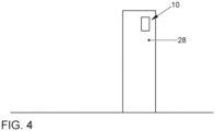
- FIG. 4 shows a schematic representation of a charging station 28 according to claims 1 to 11.
Landscapes
- Engineering & Computer Science (AREA)
- Physics & Mathematics (AREA)
- General Physics & Mathematics (AREA)
- Power Engineering (AREA)
- Transportation (AREA)
- Mechanical Engineering (AREA)
- Computer Networks & Wireless Communication (AREA)
- Business, Economics & Management (AREA)
- Emergency Management (AREA)
- Multimedia (AREA)
- Computer Security & Cryptography (AREA)
- Burglar Alarm Systems (AREA)
Claims (13)
- Colonne de charge (28) pour la charge d'un véhicule et comprenant un système (10) pour la reconnaissance et l'avertissement de vol et de vandalisme comprenant une unité de commande et de calcul (12) comportant un programme d'évaluation (14) ainsi qu'une pluralité d'éléments capteurs (16, 18, 22, 24, 26) distincts qui sont conçus pour détecter des états de la colonne de charge (28), dans laquelle au moins une unité de chaque élément capteur (16, 18, 22, 24, 26) distinct est prévue et des éléments capteurs (16, 18, 22, 24, 26) respectifs sont couplés respectivement à l'unité de commande et de calcul (12), de sorte que des états respectifs des éléments capteurs (16, 18, 22, 24, 26) peuvent être détectés et/ou commandés, et au moins un élément actionneur (20) pour l'émission d'un signal d'avertissement,caractérisée en ce que, dans l'état activé du système (10), au moins un capteur d'inclinaison (16) et au moins un capteur de mouvement (18) sont activés (S252), de sorte qu'un changement d'état respectif de l'au moins un capteur d'inclinaison (16) et/ou de l'au moins un capteur de mouvement (18) peut être détecté (S254) à l'aide de l'unité de commande et de calcul (12),dans laquelle une reconnaissance de l'environnement (S256, S262) est effectuée à l'aide d'un changement d'état, détecté à l'aide de l'unité de commande et de calcul (12), de l'au moins un capteur d'inclinaison (16) et/ou de l'au moins un capteur de mouvement (18) et, lorsqu'un mouvement est reconnu à l'aide du capteur de mouvement (18), un éclairage de la colonne de charge (28) ainsi qu'un avertisseur acoustique et/ou optique de la colonne de charge (28) sont activés (S258, S260) et une activation (S270, S272, S274) d'un capteur d'accélération, d'un capteur de choc et/ou d'un capteur de luminosité de la colonne de charge (28) est effectuée,de sorte qu'une évaluation (S276, S278) du capteur d'accélération, du capteur de choc et/ou du capteur de luminosité activés peut être réalisée à l'aide de l'unité de commande et de calcul (12) pour la reconnaissance d'une action mécanique sur la colonne de charge (28) et, en fonction d'un résultat de l'évaluation du capteur d'accélération, capteur de choc et/ou capteur de luminosité activés, une routine d'action prévue à cet effet et enregistrée dans le programme d'évaluation (14) peut être déclenchée (S280) lorsqu'au moins une valeur de capteur du capteur d'accélération, du capteur de choc et/ou du capteur de luminosité activés se situe en dehors d'une valeur seuil prédéterminée,dans laquelle la routine d'action comprend une activation (S268) d'une unité de communication et une transmission d'une information concernant l'état actuel de la colonne de charge (28) à un opérateur, etdans laquelle la routine d'action comprend en outre une activation (S282) de l'au moins un élément actionneur (20) pour l'émission du signal d'avertissement et une mise hors tension d'une électronique de puissance de la colonne de charge (28).
- Colonne de charge (28) selon l'une des revendications précédentes, dans laquelle l'information concernant l'état actuel de la colonne de charge (28) comprend au moins une valeur de capteur d'au moins un capteur activé.
- Colonne de charge (28) selon l'une des revendications précédentes, dans laquelle l'au moins un élément actionneur (20) est choisi parmi : haut-parleur, unité d'écran, élément d'éclairage extérieur, dispositif de compensation de l'inclinaison, en particulier dispositif de compensation de l'inclinaison comportant au moins un servomoteur, élément lumineux d'avertissement.
- Colonne de charge (28) selon l'une des revendications précédentes, dans laquelle, après la mise hors tension d'une électronique de puissance de la colonne de charge (28), un contrôle de fonctionnement du système (10) peut être déclenché de manière définie par l'utilisateur.
- Colonne de charge (28) selon la revendication 4, dans laquelle le contrôle de fonctionnement comprend une routine de test respective pour les différents éléments capteurs (16, 18, 22, 24, 26) distincts.
- Colonne de charge (28) selon l'une des revendications précédentes 4 à 5, dans laquelle le contrôle de fonctionnement comprend une routine de test respective pour l'au moins un élément actionneur (20).
- Colonne de charge (28) selon l'une des revendications précédentes 5 à 6, dans laquelle des résultats de test respectifs des routines de test individuelles peuvent être évalués ensemble à l'aide de l'unité de commande et de calcul (12) comportant un programme d'évaluation (14), de sorte que des erreurs multiples peuvent être détectées.
- Colonne de charge (28) selon l'une des revendications précédentes 5 à 7, dans laquelle les routines de test respectives pour les différents éléments capteurs (16, 18, 22, 24, 26) sont conçues pour permettre aux valeurs actuelles mesurées respectives des différents éléments capteurs (16, 18, 22, 24, 26) distincts respectifs d'être comparées avec des valeurs attendues respectives enregistrées dans l'unité de commande et de calcul (12) comportant un programme d'évaluation (14), de sorte qu'une ampleur d'une erreur peut être constatée et de sorte qu'en fonction de cette ampleur, au moins une autre routine d'action enregistrée dans le programme d'évaluation (14) peut être déclenchée.
- Colonne de charge (28)) selon l'une des revendications précédentes, dans laquelle une autre routine d'action comprend une activation d'un dispositif de localisation de position.
- Colonne de charge (28) selon l'une des revendications précédentes, dans laquelle l'unité de communication est basée sur la téléphonie mobile et/ou une technologie WiFi.
- Colonne de charge (28) selon l'une des revendications précédentes, dans laquelle, avant une activation respective du système (10), une routine de démarrage pouvant être déclenchée de manière définie par l'utilisateur, qui comprend une routine de test respective pour les différents éléments capteurs (16, 18, 22, 24, 26) distincts et/ou un contrôle d'isolation de l'électronique de puissance de la colonne de charge (28) et/ou un contrôle de la batterie, peut être réalisée.
- Procédé pour la reconnaissance et l'avertissement de vol et de vandalisme pour des colonnes de charge pour véhicules, comprenant les étapes suivantes :• mise à disposition d'une unité de commande et de calcul (12) comportant un programme d'évaluation (14) ;• mise à disposition d'une pluralité d'éléments capteurs (16, 18, 22, 24, 26) distincts qui sont conçus pour détecter des états de la colonne de charge (28), dans lequel au moins une unité de chaque élément capteur (16, 18, 22, 24, 26) distinct est prévue et des éléments capteurs (16, 18, 22, 24, 26) respectifs sont couplés respectivement à l'unité de commande et de calcul (12), de sorte que des états respectifs des éléments capteurs (16, 18, 22, 24, 26) peuvent être détectés et/ou commandés ;• mise à disposition d'au moins un élément actionneur (20) pour l'émission d'un signal d'avertissement, caractérisé en ce que le procédé comprend en outre les étapes supplémentaires suivantes :• activation (S252) d'au moins un capteur d'inclinaison (16) et d'au moins un capteur de mouvement (18), de sorte qu'un changement d'état respectif de l'au moins un capteur d'inclinaison (16) et/ou de l'au moins un capteur de mouvement (18) peut être détecté (S254) à l'aide de l'unité de commande et de calcul (12),• réalisation d'une reconnaissance de l'environnement (S256, S262) à l'aide d'un changement d'état détecté de l'au moins un capteur d'inclinaison (16) et/ou de l'au moins un capteur de mouvement (18) et activation (S258) d'un éclairage de la colonne de charge (28), (S260) d'un avertisseur acoustique et/ou optique de la colonne de charge (28) et d'un (S270) capteur d'accélération, (S272) capteur de choc et/ou (S274) capteur de luminosité de la colonne de charge (28), lorsqu'un mouvement est reconnu à l'aide du capteur de mouvement (18),
reconnaissance (S276) d'une action mécanique sur la colonne de charge (29) par évaluation (S278) du capteur d'accélération, du capteur de choc et/ou du capteur de luminosité activés à l'aide de l'unité de commande et de calcul (12) et, en fonction d'un résultat de l'évaluation du capteur d'accélération, capteur de choc et/ou capteur de luminosité activés, déclenchement (S280) d'une routine d'action prévue à cet effet et respectivement enregistrée dans le programme d'évaluation (14), lorsqu'au moins une valeur de capteur du capteur d'accélération, du capteur de choc et/ou du capteur de luminosité activés se situe en dehors d'une valeur seuil prédéterminée,• dans lequel la routine d'action comprend une activation (S268) d'une unité de communication et une transmission d'une information concernant l'état actuel de la colonne de charge (28) à un opérateur, et• dans lequel la routine d'action comprenant en outre une activation (S282) de l'au moins un élément actionneur (20) pour l'émission du signal d'avertissement et une mise hors tension d'une électronique de puissance de la colonne de charge (28). - Produit programme d'ordinateur comprenant des instructions qui, lorsque le procédé est exécuté par un ordinateur sur une colonne de charge selon la revendication 1, amènent l'ordinateur à exécuter le procédé selon la revendication 12.
Priority Applications (2)
| Application Number | Priority Date | Filing Date | Title |
|---|---|---|---|
| EP20153013.6A EP3854629B1 (fr) | 2020-01-22 | 2020-01-22 | Système et procédé de détection et d'avertissement de vol et de vandalisme pour colonnes de charge pour véhicules |
| CN202110086142.4A CN113160511A (zh) | 2020-01-22 | 2021-01-22 | 车辆的充电桩的盗窃和故意破坏识别和报警的系统和方法 |
Applications Claiming Priority (1)
| Application Number | Priority Date | Filing Date | Title |
|---|---|---|---|
| EP20153013.6A EP3854629B1 (fr) | 2020-01-22 | 2020-01-22 | Système et procédé de détection et d'avertissement de vol et de vandalisme pour colonnes de charge pour véhicules |
Publications (2)
| Publication Number | Publication Date |
|---|---|
| EP3854629A1 EP3854629A1 (fr) | 2021-07-28 |
| EP3854629B1 true EP3854629B1 (fr) | 2025-03-12 |
Family
ID=69187592
Family Applications (1)
| Application Number | Title | Priority Date | Filing Date |
|---|---|---|---|
| EP20153013.6A Active EP3854629B1 (fr) | 2020-01-22 | 2020-01-22 | Système et procédé de détection et d'avertissement de vol et de vandalisme pour colonnes de charge pour véhicules |
Country Status (2)
| Country | Link |
|---|---|
| EP (1) | EP3854629B1 (fr) |
| CN (1) | CN113160511A (fr) |
Families Citing this family (8)
| Publication number | Priority date | Publication date | Assignee | Title |
|---|---|---|---|---|
| CN114435171B (zh) * | 2022-02-08 | 2022-09-27 | 北京智充科技有限公司 | 一种倾斜充电桩充电管理方法、装置、电子设备及介质 |
| CN115035698B (zh) * | 2022-06-06 | 2024-04-26 | 大牧人机械(胶州)有限公司 | 一种猪场集中报警设备冗余系统及自检方法 |
| DE102022214132A1 (de) * | 2022-12-21 | 2024-06-27 | Magna powertrain gmbh & co kg | Überwachungssystem mit Überwachungsmodul zur Überwachung des Zustands einer Ladestation, insbesondere des elektrischen Ladeanschlusses, sowie Verfahren zur Überwachung des Zustandes einer Ladesäule |
| WO2024132973A1 (fr) * | 2022-12-21 | 2024-06-27 | Magna powertrain gmbh & co kg | Surveillance de l'état d'une colonne de recharge à fonction d'alarme |
| DE102022214126B3 (de) * | 2022-12-21 | 2024-03-28 | Magna powertrain gmbh & co kg | Sensormodul zur Erfassung von Umfelddaten für Ladeplätze, sowie Ladeinfrastruktur |
| DE102023108880B4 (de) * | 2023-04-06 | 2025-05-15 | Bender Gmbh & Co. Kg | Wandladestation zum Anschließen eines Ladekabels für die Verbindung mit einem Elektrofahrzeug |
| DE102023113328A1 (de) * | 2023-05-22 | 2024-11-28 | Libreo GmbH | Einrichtung und Verfahren zur Überwachung einer Ladestation |
| CN117755114A (zh) * | 2023-12-14 | 2024-03-26 | 壳牌(北京)新能源科技有限公司 | 一种电动汽车充电桩的充电枪防盗方法 |
Citations (1)
| Publication number | Priority date | Publication date | Assignee | Title |
|---|---|---|---|---|
| CN107038828A (zh) * | 2017-06-13 | 2017-08-11 | 山东博恒新能源有限公司 | 防盗系统及充电机防盗装置 |
Family Cites Families (10)
| Publication number | Priority date | Publication date | Assignee | Title |
|---|---|---|---|---|
| CN2702549Y (zh) * | 2004-06-25 | 2005-05-25 | 万腾驰 | 带巡检功能的无线自动拨号报警器 |
| DE102010009657A1 (de) | 2010-02-27 | 2011-09-01 | Gm Global Technology Operations Llc , ( N. D. Ges. D. Staates Delaware ) | Vorrichtung und Verfahren zur Überwachung eines Ladekabels für ein Fahrzeug |
| US20140267712A1 (en) * | 2013-03-15 | 2014-09-18 | Eaton Corporation | Theft alert system for electric vehicle charging cable |
| DE102013206687A1 (de) | 2013-04-15 | 2014-10-16 | Siemens Aktiengesellschaft | Bereitstellen eines Warnsignales für eine Ladesäule |
| CN103426246B (zh) * | 2013-07-26 | 2016-01-20 | 国家电网公司 | 一种具有防开启监控功能的充电桩 |
| CN104361701A (zh) * | 2014-10-31 | 2015-02-18 | 武汉市德鸣电力设备有限公司 | 一种变压器防盗窃装置 |
| US10769914B2 (en) * | 2017-06-07 | 2020-09-08 | Amazon Technologies, Inc. | Informative image data generation using audio/video recording and communication devices |
| CN206863882U (zh) * | 2017-06-13 | 2018-01-09 | 山东博恒新能源有限公司 | 防盗系统及充电机防盗装置 |
| DE102017215882A1 (de) | 2017-09-08 | 2019-03-14 | Volkswagen Aktiengesellschaft | Vorrichtung zur Ladung eines elektrochemischen Traktionsenergiespeichers eines Fortbewegungsmittels |
| CN109450044A (zh) * | 2018-12-20 | 2019-03-08 | 四川铸新嘉舟新能源科技有限公司 | 充电桩电能管理方法及系统 |
-
2020
- 2020-01-22 EP EP20153013.6A patent/EP3854629B1/fr active Active
-
2021
- 2021-01-22 CN CN202110086142.4A patent/CN113160511A/zh active Pending
Patent Citations (1)
| Publication number | Priority date | Publication date | Assignee | Title |
|---|---|---|---|---|
| CN107038828A (zh) * | 2017-06-13 | 2017-08-11 | 山东博恒新能源有限公司 | 防盗系统及充电机防盗装置 |
Also Published As
| Publication number | Publication date |
|---|---|
| EP3854629A1 (fr) | 2021-07-28 |
| CN113160511A (zh) | 2021-07-23 |
Similar Documents
| Publication | Publication Date | Title |
|---|---|---|
| EP3854629A1 (fr) | Système et procédé de détection et d'avertissement de vol et de vandalisme pour colonnes de charge pour véhicules | |
| EP3347787B1 (fr) | Procédé et dispositif pour faire fonctionner un véhicule | |
| DE102013001307B4 (de) | Verfahren zum Überwachen einer Kraftwagenumgebung | |
| DE102017111169A1 (de) | Systeme und verfahren zum überwachen eines stellplatzes | |
| DE102013112449A1 (de) | Fußgängerkollisions-Erfassungsvorrichtung, Fußgängerkollisions-Meldevorrichtung und Fahrzeugkollisions-Erfassungsvorrichtung | |
| DE102010001006A1 (de) | Verfahren zum Bereitstellen wenigstens einer Information über einen Unfall zwischen mindestens zwei Fahrzeugen | |
| DE112016004282T5 (de) | Drahtbrückenüberwachungssystem | |
| DE10223123A1 (de) | Erfassungsvorrichtung | |
| DE602004011587T2 (de) | Anordnung und System zur Überwachung | |
| DE102016216522A1 (de) | Verfahren zum Bereitstellen wenigstens einer Information über einen Unfall zwischen mindestens zwei Verkehrsteilnehmern | |
| EP4281308A1 (fr) | Procédé de fourniture d'une information d'état relative à une batterie à haute tension d'un véhicule automobile, et dispositif de fourniture | |
| WO2008065046A1 (fr) | Procédé et dispositif de surveillance d'un objet en particulier portatif, au moyen d'un signal radio | |
| DE102013016356A1 (de) | Verfahren zum Nutzen eines Kamerasystems eines Kraftfahrzeugs als Diebstahlwarnanlage, Kamerasystem und Kraftfahrzeug | |
| DE102015012311A1 (de) | Verfahren und System zum Übermitteln eines Notrufdatensatzes | |
| DE10341426A1 (de) | Verfahren zur Raumüberwachung und Raumüberwachungsanlage | |
| EP3947049A1 (fr) | Système de détection d'endommagement et de suivi de responsable | |
| DE102014207810A1 (de) | Verfahren und Vorrichtung zum Betreiben eines Kraftfahrzeugs | |
| DE102014200567A1 (de) | Verfahren zur automatischen Übertragung von Bild- und/oder Audiodaten im Zusammenhang mit einem Unfall eines Fahrzeugs | |
| DE19744602A1 (de) | Telematikmodul für Kraftfahrzeuge | |
| DE102022128225A1 (de) | Verfahren und systeme zum steuern von fahrerassistenzsystemen | |
| DE102020215885A1 (de) | Verfahren und system zur erkennung und mitigation von störungen | |
| DE102020106237B4 (de) | Unfallschaden-Detektionssystem mit Niedrigenergie-Echtzeit-Signalauswertung | |
| DE102009029748A1 (de) | Verfahren, System und sicheres Identifikationsmodul zum Benachrichten einer Instanz | |
| EP3446297B1 (fr) | Dispositif de détection, procédé de surveillance d'un état d'occupation d'un emplacement de stationnement d'un parc de stationnement et parc de stationnement | |
| DE102018222680A1 (de) | System zum Überwachen von parkenden Fahrzeugen |
Legal Events
| Date | Code | Title | Description |
|---|---|---|---|
| PUAI | Public reference made under article 153(3) epc to a published international application that has entered the european phase |
Free format text: ORIGINAL CODE: 0009012 |
|
| STAA | Information on the status of an ep patent application or granted ep patent |
Free format text: STATUS: THE APPLICATION HAS BEEN PUBLISHED |
|
| AK | Designated contracting states |
Kind code of ref document: A1 Designated state(s): AL AT BE BG CH CY CZ DE DK EE ES FI FR GB GR HR HU IE IS IT LI LT LU LV MC MK MT NL NO PL PT RO RS SE SI SK SM TR |
|
| STAA | Information on the status of an ep patent application or granted ep patent |
Free format text: STATUS: REQUEST FOR EXAMINATION WAS MADE |
|
| 17P | Request for examination filed |
Effective date: 20220128 |
|
| RBV | Designated contracting states (corrected) |
Designated state(s): AL AT BE BG CH CY CZ DE DK EE ES FI FR GB GR HR HU IE IS IT LI LT LU LV MC MK MT NL NO PL PT RO RS SE SI SK SM TR |
|
| STAA | Information on the status of an ep patent application or granted ep patent |
Free format text: STATUS: EXAMINATION IS IN PROGRESS |
|
| 17Q | First examination report despatched |
Effective date: 20230109 |
|
| GRAP | Despatch of communication of intention to grant a patent |
Free format text: ORIGINAL CODE: EPIDOSNIGR1 |
|
| STAA | Information on the status of an ep patent application or granted ep patent |
Free format text: STATUS: GRANT OF PATENT IS INTENDED |
|
| INTG | Intention to grant announced |
Effective date: 20241028 |
|
| RAP3 | Party data changed (applicant data changed or rights of an application transferred) |
Owner name: VOLKSWAGEN AKTIENGESELLSCHAFT |
|
| GRAS | Grant fee paid |
Free format text: ORIGINAL CODE: EPIDOSNIGR3 |
|
| GRAA | (expected) grant |
Free format text: ORIGINAL CODE: 0009210 |
|
| STAA | Information on the status of an ep patent application or granted ep patent |
Free format text: STATUS: THE PATENT HAS BEEN GRANTED |
|
| AK | Designated contracting states |
Kind code of ref document: B1 Designated state(s): AL AT BE BG CH CY CZ DE DK EE ES FI FR GB GR HR HU IE IS IT LI LT LU LV MC MK MT NL NO PL PT RO RS SE SI SK SM TR |
|
| REG | Reference to a national code |
Ref country code: GB Ref legal event code: FG4D Free format text: NOT ENGLISH |
|
| REG | Reference to a national code |
Ref country code: CH Ref legal event code: EP |
|
| REG | Reference to a national code |
Ref country code: DE Ref legal event code: R096 Ref document number: 502020010562 Country of ref document: DE |
|
| REG | Reference to a national code |
Ref country code: IE Ref legal event code: FG4D Free format text: LANGUAGE OF EP DOCUMENT: GERMAN |
|
| P01 | Opt-out of the competence of the unified patent court (upc) registered |
Free format text: CASE NUMBER: APP_11154/2025 Effective date: 20250306 |
|
| PG25 | Lapsed in a contracting state [announced via postgrant information from national office to epo] |
Ref country code: RS Free format text: LAPSE BECAUSE OF FAILURE TO SUBMIT A TRANSLATION OF THE DESCRIPTION OR TO PAY THE FEE WITHIN THE PRESCRIBED TIME-LIMIT Effective date: 20250612 |
|
| PG25 | Lapsed in a contracting state [announced via postgrant information from national office to epo] |
Ref country code: FI Free format text: LAPSE BECAUSE OF FAILURE TO SUBMIT A TRANSLATION OF THE DESCRIPTION OR TO PAY THE FEE WITHIN THE PRESCRIBED TIME-LIMIT Effective date: 20250312 |
|
| PG25 | Lapsed in a contracting state [announced via postgrant information from national office to epo] |
Ref country code: ES Free format text: LAPSE BECAUSE OF FAILURE TO SUBMIT A TRANSLATION OF THE DESCRIPTION OR TO PAY THE FEE WITHIN THE PRESCRIBED TIME-LIMIT Effective date: 20250312 |
|
| REG | Reference to a national code |
Ref country code: LT Ref legal event code: MG9D |
|
| PG25 | Lapsed in a contracting state [announced via postgrant information from national office to epo] |
Ref country code: NO Free format text: LAPSE BECAUSE OF FAILURE TO SUBMIT A TRANSLATION OF THE DESCRIPTION OR TO PAY THE FEE WITHIN THE PRESCRIBED TIME-LIMIT Effective date: 20250612 |
|
| PG25 | Lapsed in a contracting state [announced via postgrant information from national office to epo] |
Ref country code: HR Free format text: LAPSE BECAUSE OF FAILURE TO SUBMIT A TRANSLATION OF THE DESCRIPTION OR TO PAY THE FEE WITHIN THE PRESCRIBED TIME-LIMIT Effective date: 20250312 |
|
| REG | Reference to a national code |
Ref country code: NL Ref legal event code: MP Effective date: 20250312 |
|
| PG25 | Lapsed in a contracting state [announced via postgrant information from national office to epo] |
Ref country code: LV Free format text: LAPSE BECAUSE OF FAILURE TO SUBMIT A TRANSLATION OF THE DESCRIPTION OR TO PAY THE FEE WITHIN THE PRESCRIBED TIME-LIMIT Effective date: 20250312 |
|
| PG25 | Lapsed in a contracting state [announced via postgrant information from national office to epo] |
Ref country code: BG Free format text: LAPSE BECAUSE OF FAILURE TO SUBMIT A TRANSLATION OF THE DESCRIPTION OR TO PAY THE FEE WITHIN THE PRESCRIBED TIME-LIMIT Effective date: 20250312 Ref country code: GR Free format text: LAPSE BECAUSE OF FAILURE TO SUBMIT A TRANSLATION OF THE DESCRIPTION OR TO PAY THE FEE WITHIN THE PRESCRIBED TIME-LIMIT Effective date: 20250613 |
|
| PG25 | Lapsed in a contracting state [announced via postgrant information from national office to epo] |
Ref country code: NL Free format text: LAPSE BECAUSE OF FAILURE TO SUBMIT A TRANSLATION OF THE DESCRIPTION OR TO PAY THE FEE WITHIN THE PRESCRIBED TIME-LIMIT Effective date: 20250312 |
|
| PG25 | Lapsed in a contracting state [announced via postgrant information from national office to epo] |
Ref country code: SE Free format text: LAPSE BECAUSE OF FAILURE TO SUBMIT A TRANSLATION OF THE DESCRIPTION OR TO PAY THE FEE WITHIN THE PRESCRIBED TIME-LIMIT Effective date: 20250312 |
|
| PG25 | Lapsed in a contracting state [announced via postgrant information from national office to epo] |
Ref country code: SM Free format text: LAPSE BECAUSE OF FAILURE TO SUBMIT A TRANSLATION OF THE DESCRIPTION OR TO PAY THE FEE WITHIN THE PRESCRIBED TIME-LIMIT Effective date: 20250312 |
|
| PG25 | Lapsed in a contracting state [announced via postgrant information from national office to epo] |
Ref country code: PT Free format text: LAPSE BECAUSE OF FAILURE TO SUBMIT A TRANSLATION OF THE DESCRIPTION OR TO PAY THE FEE WITHIN THE PRESCRIBED TIME-LIMIT Effective date: 20250714 |
|
| PG25 | Lapsed in a contracting state [announced via postgrant information from national office to epo] |
Ref country code: PL Free format text: LAPSE BECAUSE OF FAILURE TO SUBMIT A TRANSLATION OF THE DESCRIPTION OR TO PAY THE FEE WITHIN THE PRESCRIBED TIME-LIMIT Effective date: 20250312 Ref country code: IT Free format text: LAPSE BECAUSE OF FAILURE TO SUBMIT A TRANSLATION OF THE DESCRIPTION OR TO PAY THE FEE WITHIN THE PRESCRIBED TIME-LIMIT Effective date: 20250312 |
|
| PG25 | Lapsed in a contracting state [announced via postgrant information from national office to epo] |
Ref country code: CZ Free format text: LAPSE BECAUSE OF FAILURE TO SUBMIT A TRANSLATION OF THE DESCRIPTION OR TO PAY THE FEE WITHIN THE PRESCRIBED TIME-LIMIT Effective date: 20250312 Ref country code: EE Free format text: LAPSE BECAUSE OF FAILURE TO SUBMIT A TRANSLATION OF THE DESCRIPTION OR TO PAY THE FEE WITHIN THE PRESCRIBED TIME-LIMIT Effective date: 20250312 |
|
| PG25 | Lapsed in a contracting state [announced via postgrant information from national office to epo] |
Ref country code: RO Free format text: LAPSE BECAUSE OF FAILURE TO SUBMIT A TRANSLATION OF THE DESCRIPTION OR TO PAY THE FEE WITHIN THE PRESCRIBED TIME-LIMIT Effective date: 20250312 |
|
| PG25 | Lapsed in a contracting state [announced via postgrant information from national office to epo] |
Ref country code: SK Free format text: LAPSE BECAUSE OF FAILURE TO SUBMIT A TRANSLATION OF THE DESCRIPTION OR TO PAY THE FEE WITHIN THE PRESCRIBED TIME-LIMIT Effective date: 20250312 |
|
| PG25 | Lapsed in a contracting state [announced via postgrant information from national office to epo] |
Ref country code: IS Free format text: LAPSE BECAUSE OF FAILURE TO SUBMIT A TRANSLATION OF THE DESCRIPTION OR TO PAY THE FEE WITHIN THE PRESCRIBED TIME-LIMIT Effective date: 20250712 |
|
| REG | Reference to a national code |
Ref country code: DE Ref legal event code: R097 Ref document number: 502020010562 Country of ref document: DE |
|
| PG25 | Lapsed in a contracting state [announced via postgrant information from national office to epo] |
Ref country code: DK Free format text: LAPSE BECAUSE OF FAILURE TO SUBMIT A TRANSLATION OF THE DESCRIPTION OR TO PAY THE FEE WITHIN THE PRESCRIBED TIME-LIMIT Effective date: 20250312 |
|
| PLBE | No opposition filed within time limit |
Free format text: ORIGINAL CODE: 0009261 |
|
| STAA | Information on the status of an ep patent application or granted ep patent |
Free format text: STATUS: NO OPPOSITION FILED WITHIN TIME LIMIT |
|
| REG | Reference to a national code |
Ref country code: CH Ref legal event code: L10 Free format text: ST27 STATUS EVENT CODE: U-0-0-L10-L00 (AS PROVIDED BY THE NATIONAL OFFICE) Effective date: 20260121 |
|
| 26N | No opposition filed |
Effective date: 20251215 |
|
| PGFP | Annual fee paid to national office [announced via postgrant information from national office to epo] |
Ref country code: GB Payment date: 20260126 Year of fee payment: 7 |
|
| PGFP | Annual fee paid to national office [announced via postgrant information from national office to epo] |
Ref country code: DE Payment date: 20260131 Year of fee payment: 7 |
|
| PGFP | Annual fee paid to national office [announced via postgrant information from national office to epo] |
Ref country code: FR Payment date: 20260126 Year of fee payment: 7 |