EP3854633A1 - Composant de carrosserie de véhicule et procédé de fabrication d'un composant de carrosserie de véhicule et procédé de commande d'un agencement de moyen d'éclairage - Google Patents
Composant de carrosserie de véhicule et procédé de fabrication d'un composant de carrosserie de véhicule et procédé de commande d'un agencement de moyen d'éclairage Download PDFInfo
- Publication number
- EP3854633A1 EP3854633A1 EP21152212.3A EP21152212A EP3854633A1 EP 3854633 A1 EP3854633 A1 EP 3854633A1 EP 21152212 A EP21152212 A EP 21152212A EP 3854633 A1 EP3854633 A1 EP 3854633A1
- Authority
- EP
- European Patent Office
- Prior art keywords
- leds
- vehicle body
- body component
- arrangement
- designed
- Prior art date
- Legal status (The legal status is an assumption and is not a legal conclusion. Google has not performed a legal analysis and makes no representation as to the accuracy of the status listed.)
- Withdrawn
Links
Images


Classifications
-
- B—PERFORMING OPERATIONS; TRANSPORTING
- B60—VEHICLES IN GENERAL
- B60Q—ARRANGEMENT OF SIGNALLING OR LIGHTING DEVICES, THE MOUNTING OR SUPPORTING THEREOF OR CIRCUITS THEREFOR, FOR VEHICLES IN GENERAL
- B60Q1/00—Arrangement of optical signalling or lighting devices, the mounting or supporting thereof or circuits therefor
- B60Q1/26—Arrangement of optical signalling or lighting devices, the mounting or supporting thereof or circuits therefor the devices being primarily intended to indicate the vehicle, or parts thereof, or to give signals, to other traffic
- B60Q1/2661—Arrangement of optical signalling or lighting devices, the mounting or supporting thereof or circuits therefor the devices being primarily intended to indicate the vehicle, or parts thereof, or to give signals, to other traffic mounted on parts having other functions
-
- B—PERFORMING OPERATIONS; TRANSPORTING
- B60—VEHICLES IN GENERAL
- B60Q—ARRANGEMENT OF SIGNALLING OR LIGHTING DEVICES, THE MOUNTING OR SUPPORTING THEREOF OR CIRCUITS THEREFOR, FOR VEHICLES IN GENERAL
- B60Q1/00—Arrangement of optical signalling or lighting devices, the mounting or supporting thereof or circuits therefor
- B60Q1/26—Arrangement of optical signalling or lighting devices, the mounting or supporting thereof or circuits therefor the devices being primarily intended to indicate the vehicle, or parts thereof, or to give signals, to other traffic
- B60Q1/2696—Mounting of devices using LEDs
-
- B—PERFORMING OPERATIONS; TRANSPORTING
- B60—VEHICLES IN GENERAL
- B60Q—ARRANGEMENT OF SIGNALLING OR LIGHTING DEVICES, THE MOUNTING OR SUPPORTING THEREOF OR CIRCUITS THEREFOR, FOR VEHICLES IN GENERAL
- B60Q1/00—Arrangement of optical signalling or lighting devices, the mounting or supporting thereof or circuits therefor
- B60Q1/26—Arrangement of optical signalling or lighting devices, the mounting or supporting thereof or circuits therefor the devices being primarily intended to indicate the vehicle, or parts thereof, or to give signals, to other traffic
- B60Q1/28—Arrangement of optical signalling or lighting devices, the mounting or supporting thereof or circuits therefor the devices being primarily intended to indicate the vehicle, or parts thereof, or to give signals, to other traffic for indicating front of vehicle
-
- B—PERFORMING OPERATIONS; TRANSPORTING
- B60—VEHICLES IN GENERAL
- B60Q—ARRANGEMENT OF SIGNALLING OR LIGHTING DEVICES, THE MOUNTING OR SUPPORTING THEREOF OR CIRCUITS THEREFOR, FOR VEHICLES IN GENERAL
- B60Q1/00—Arrangement of optical signalling or lighting devices, the mounting or supporting thereof or circuits therefor
- B60Q1/26—Arrangement of optical signalling or lighting devices, the mounting or supporting thereof or circuits therefor the devices being primarily intended to indicate the vehicle, or parts thereof, or to give signals, to other traffic
- B60Q1/50—Arrangement of optical signalling or lighting devices, the mounting or supporting thereof or circuits therefor the devices being primarily intended to indicate the vehicle, or parts thereof, or to give signals, to other traffic for indicating other intentions or conditions, e.g. request for waiting or overtaking
- B60Q1/503—Arrangement of optical signalling or lighting devices, the mounting or supporting thereof or circuits therefor the devices being primarily intended to indicate the vehicle, or parts thereof, or to give signals, to other traffic for indicating other intentions or conditions, e.g. request for waiting or overtaking using luminous text or symbol displays in or on the vehicle, e.g. static text
- B60Q1/5035—Arrangement of optical signalling or lighting devices, the mounting or supporting thereof or circuits therefor the devices being primarily intended to indicate the vehicle, or parts thereof, or to give signals, to other traffic for indicating other intentions or conditions, e.g. request for waiting or overtaking using luminous text or symbol displays in or on the vehicle, e.g. static text electronic displays
-
- B—PERFORMING OPERATIONS; TRANSPORTING
- B60—VEHICLES IN GENERAL
- B60Q—ARRANGEMENT OF SIGNALLING OR LIGHTING DEVICES, THE MOUNTING OR SUPPORTING THEREOF OR CIRCUITS THEREFOR, FOR VEHICLES IN GENERAL
- B60Q1/00—Arrangement of optical signalling or lighting devices, the mounting or supporting thereof or circuits therefor
- B60Q1/26—Arrangement of optical signalling or lighting devices, the mounting or supporting thereof or circuits therefor the devices being primarily intended to indicate the vehicle, or parts thereof, or to give signals, to other traffic
- B60Q1/50—Arrangement of optical signalling or lighting devices, the mounting or supporting thereof or circuits therefor the devices being primarily intended to indicate the vehicle, or parts thereof, or to give signals, to other traffic for indicating other intentions or conditions, e.g. request for waiting or overtaking
- B60Q1/543—Arrangement of optical signalling or lighting devices, the mounting or supporting thereof or circuits therefor the devices being primarily intended to indicate the vehicle, or parts thereof, or to give signals, to other traffic for indicating other intentions or conditions, e.g. request for waiting or overtaking for indicating other states or conditions of the vehicle
-
- B—PERFORMING OPERATIONS; TRANSPORTING
- B60—VEHICLES IN GENERAL
- B60R—VEHICLES, VEHICLE FITTINGS, OR VEHICLE PARTS, NOT OTHERWISE PROVIDED FOR
- B60R19/00—Wheel guards; Radiator guards, e.g. grilles; Obstruction removers; Fittings damping bouncing force in collisions
- B60R19/52—Radiator or grille guards ; Radiator grilles
-
- F—MECHANICAL ENGINEERING; LIGHTING; HEATING; WEAPONS; BLASTING
- F21—LIGHTING
- F21S—NON-PORTABLE LIGHTING DEVICES; SYSTEMS THEREOF; VEHICLE LIGHTING DEVICES SPECIALLY ADAPTED FOR VEHICLE EXTERIORS
- F21S43/00—Signalling devices specially adapted for vehicle exteriors, e.g. brake lamps, direction indicator lights or reversing lights
- F21S43/10—Signalling devices specially adapted for vehicle exteriors, e.g. brake lamps, direction indicator lights or reversing lights characterised by the light source
- F21S43/13—Signalling devices specially adapted for vehicle exteriors, e.g. brake lamps, direction indicator lights or reversing lights characterised by the light source characterised by the type of light source
- F21S43/14—Light emitting diodes [LED]
-
- F—MECHANICAL ENGINEERING; LIGHTING; HEATING; WEAPONS; BLASTING
- F21—LIGHTING
- F21S—NON-PORTABLE LIGHTING DEVICES; SYSTEMS THEREOF; VEHICLE LIGHTING DEVICES SPECIALLY ADAPTED FOR VEHICLE EXTERIORS
- F21S43/00—Signalling devices specially adapted for vehicle exteriors, e.g. brake lamps, direction indicator lights or reversing lights
- F21S43/10—Signalling devices specially adapted for vehicle exteriors, e.g. brake lamps, direction indicator lights or reversing lights characterised by the light source
- F21S43/13—Signalling devices specially adapted for vehicle exteriors, e.g. brake lamps, direction indicator lights or reversing lights characterised by the light source characterised by the type of light source
- F21S43/15—Strips of light sources
-
- B—PERFORMING OPERATIONS; TRANSPORTING
- B60—VEHICLES IN GENERAL
- B60Q—ARRANGEMENT OF SIGNALLING OR LIGHTING DEVICES, THE MOUNTING OR SUPPORTING THEREOF OR CIRCUITS THEREFOR, FOR VEHICLES IN GENERAL
- B60Q1/00—Arrangement of optical signalling or lighting devices, the mounting or supporting thereof or circuits therefor
- B60Q1/26—Arrangement of optical signalling or lighting devices, the mounting or supporting thereof or circuits therefor the devices being primarily intended to indicate the vehicle, or parts thereof, or to give signals, to other traffic
- B60Q1/34—Arrangement of optical signalling or lighting devices, the mounting or supporting thereof or circuits therefor the devices being primarily intended to indicate the vehicle, or parts thereof, or to give signals, to other traffic for indicating change of drive direction
- B60Q1/38—Arrangement of optical signalling or lighting devices, the mounting or supporting thereof or circuits therefor the devices being primarily intended to indicate the vehicle, or parts thereof, or to give signals, to other traffic for indicating change of drive direction using immovably-mounted light sources, e.g. fixed flashing lamps
-
- B—PERFORMING OPERATIONS; TRANSPORTING
- B60—VEHICLES IN GENERAL
- B60Q—ARRANGEMENT OF SIGNALLING OR LIGHTING DEVICES, THE MOUNTING OR SUPPORTING THEREOF OR CIRCUITS THEREFOR, FOR VEHICLES IN GENERAL
- B60Q2900/00—Features of lamps not covered by other groups in B60Q
- B60Q2900/40—Several lamps activated in sequence, e.g. sweep effect, progressive activation
-
- B—PERFORMING OPERATIONS; TRANSPORTING
- B60—VEHICLES IN GENERAL
- B60R—VEHICLES, VEHICLE FITTINGS, OR VEHICLE PARTS, NOT OTHERWISE PROVIDED FOR
- B60R19/00—Wheel guards; Radiator guards, e.g. grilles; Obstruction removers; Fittings damping bouncing force in collisions
- B60R19/52—Radiator or grille guards ; Radiator grilles
- B60R2019/525—Radiator grilles
Definitions
- the present invention relates to a vehicle body component and a method for producing it and for controlling a lighting arrangement on a vehicle.
- LED strips or LED strips in which LEDs are arranged one after the other are generally known. These LED strips can be used flexibly due to their flat dimensions, their voltage only required in the low-voltage range, their versatile color emission options and their low energy consumption.
- An example of an LED strip is here EP 2 993 384 A1 mentioned. Recently, LEDs have also been taken into account as a new means of lighting for use in the automotive sector.
- the present invention is based on the object of specifying improved lighting for a vehicle.
- the idea on which the present invention is based consists in attaching the LED strip to a base body of the vehicle body component.
- the base body is designed in such a way that the LED strip is preferably received flush with the base body.
- the bendable property of the LED strip enables versatile use on different basic bodies of modern body components.
- the LED strip contains a large number of LEDs (light-emitting diodes) arranged one after the other, connected in series or in parallel, which can usually be designed as LED semiconductor chips, but also, for example, as OLED (organic light-emitting diode). Radiation over a large solid angle on a light exit side can thus be achieved.
- LEDs light-emitting diodes
- OLED organic light-emitting diode
- the LEDs which are preferably designed as LED chips, are usually encased on the LED strip in such a way that they only require a DC voltage in the low-voltage range for operation.
- the circuit is preferably designed for the operating voltage of the energy source of the vehicle, which in an ordinary vehicle is the voltage of the car battery, usually 12 volts.
- the vehicle body component comprises an assembly device which is designed to fix the illuminant arrangement.
- the LED strip can be detached from the vehicle body component can be prevented by a stable fastening to a mounting device attached to the vehicle body component or the base body or integrally connected to the base body. Fastening using such a mounting device has the advantage that the LED strip remains at the fastened point for a long period of time without detaching from the body component over a partial section or entirely. This ensures long-term use.
- the base body has at least one recess on the light exit side for receiving the illuminant arrangement.
- the LED strip is fastened or integrated to the body component in the recess of the body component by means of an assembly device which is arranged in the recess. In this way, the lighting arrangement is better protected from environmental influences.
- the depth of the recess can be designed to limit the solid angle of the emitted light.
- the vehicle body component comprises a cover for covering the recess on the light exit side.
- the cover has at least one at least partially transparent section through which at least part of the light generated by the LEDs can be emitted to the outside.
- a cover is provided over the recess, through which at least part of the light generated can be emitted to the outside through at least one transparent, partially transparent or translucent section of the cover.
- an opaque, ie opaque, section can also be provided.
- the lighting device arrangement has a substrate and an at least partially transparent outer layer.
- the LEDs are arranged between the substrate and the outer layer.
- the substrate is preferably silicon, or a silicon-based or some other semiconductor.
- a further substrate layer for example a harder substrate, or a base plate made of metal can be provided, which makes the LED strip mechanically robust.
- An insulation layer can be provided between the layers.
- the outer layer protects the LEDs from environmental influences.
- the outer layer is preferably transparent, partially transparent or translucent so that at least part of the light generated by the LEDs can be emitted outwards and in a solid angle of up to 4 ⁇ .
- the outer layer can preferably be designed to be elastic in that the outer layer contains an elastic material such as, for example, a soft plastic. As a result, the LEDs are better protected from mechanical impacts.
- the illuminant arrangement is designed to be flexible in all spatial directions. Such a mechanical flexibility increases the applicability of the illuminant arrangement, in that the illuminant arrangement can also be formed in a spiral shape or in some other 3D arrangement. This can be the case, for example, with an integration into a radiator grille extending beyond a two-dimensional lattice structure, or in body components of the cladding that are optimized in terms of flow in three dimensions, such as a bumper, a fender or a side wall.
- the LEDs are designed as white or single-colored LEDs or as RGB LEDs.
- this further development enables the illuminant arrangement to be configured in a variety of colors.
- this can be used for an improved design in order to improve a user experience for the driver or owner of the vehicle.
- the color design can also be used for a function, such as a display. For example, the charge status of a battery in an electric car can be displayed using the colors of the LEDs.
- the LEDs are arranged exclusively on a front side of the illuminant arrangement.
- the “front side” of the illuminant arrangement is defined as the side of the illuminant arrangement which, after assembly in the base body, points towards the cover or towards the light exit side of the vehicle body component. This enables uncomplicated integration into the base body of the body component, in that the rear side or the edges of the illuminant arrangement are preferably used for the assembly.
- the LEDs can be arranged in any way on the substrate, which simplifies the production of the lighting means arrangement simply through greater positioning tolerances.
- At least two contact connections for making electrical contact with the LEDs are arranged on the front side of the lighting arrangement.
- electrical lines which are generally more easily accessible, can be laid at one end of the lighting arrangement. This facilitates the contacting of the illuminant arrangement.
- the respective contact connections are arranged at an opposite or the same end of the illuminant arrangement.
- the electrical lines can be routed directly from the contact connections to an energy source. In this way, the design of the electrical lines is further simplified.
- the lighting means arrangement has at least three LEDs, which are arranged one behind the other at equal intervals on the LED strip.
- This also includes arrangements with more than three LEDs, in which all LEDs of the illuminant arrangement are arranged one behind the other at equal intervals.
- the LEDs can also be arranged one behind the other in groups of the same but different distances from group to group. With such arrangements, in connection with the cover, an outwardly acting homogeneous lighting can be achieved.
- the lighting arrangement has a light-sensitive sensor, a Zener diode or a temperature sensor.
- a temperature sensor with a corresponding circuit can enable the LEDs to be switched off automatically for safety reasons if the temperature is too high.
- a Zener diode connected anti-parallel to the LEDs can ensure that the functionality of an LED series connection with the other LEDs is maintained in the event of an LED failure.
- a light-sensitive sensor enables, for example, the LEDs to be switched on or off automatically in accordance with an ambient light.
- a control device for controlling the LEDs is provided, which is coupled to the LEDs in such a way that the LEDs can be switched on and off independently of one another.
- the control device thus enables the LEDs to be controlled individually, which can be used for further visual effects.
- the LEDs can be switched on and off according to a time pattern, which can be used specifically to improve the user experience, but also to display a signal function or warning function. Similar to a modern flashing light, a direction can be indicated by switching on the LEDs on the LED strip one after the other or one behind the other. Any operating modes, also called patterns here, for switching the LEDs on and off are conceivable.
- a radiation power of the LEDs can be controlled independently of one another by the control device.
- This provides a further functionality of the LED strip, which, similar to the previous development, can be used in a variety of ways. Changes in the radiant power of the individual LEDs can be used for a more visually appealing design and thus an enhanced user experience.
- a stepless change in the radiation power such as, for example, a "slowly” weakening or amplification of the radiation power, one can otherwise only be able to do so in stages and thus "choppy" acting changes in the lighting can be avoided.
- changes in the radiated power can also be used for warning or display functions.
- the illuminant arrangement is fixed integrally on the mounting device.
- the fastening of the lamp arrangement to the base body is designed for long-term use.
- An integral inclusion in the assembly device offers a fastening option designed for safety.
- the base body and the cover are formed in one piece or in one piece.
- Such a design is associated with less effort and therefore less costs in production, for example by injection molding, in which the lighting means arrangement is already integrated into the component during production.
- the illuminant arrangement is fixed to the assembly device as a separate component. This allows the lamp arrangement to be exchanged easily, which may be necessary, for example, due to a defect in the lamp arrangement. Nevertheless, the fastening of the lamp arrangement to the base body can be designed for long-term use.
- an outer surface of the cover on the light exit side is designed to be flush with a surface of the base body surrounding the recess. This creates a smooth surface without edges or steps between the respective surfaces of the base body and the cover.
- particularly natural-looking lighting is achieved.
- the integrated lighting arrangement is not or only with difficulty recognizable. In this way, the vehicle body component looks natural even when the lights are not switched on.
- the illuminant arrangement is fixed to the assembly device by at least one of the following options: extrusion, injection molding, gluing, locking, clipping, edging, clamping.
- fastening of the lamp arrangement to the base body is designed for long-term use.
- fastening options for the illuminant arrangement on the mounting device also offer a secure fastening.
- the latching, clipping, edging and jamming enable the lamp arrangement to be exchanged in a simple manner.
- the at least one at least partially transparent section of the cover has a transmission of a predetermined spectral range or a predetermined color.
- the spectrally selective design, preferably according to a color, of the at least partially transparent section of the cover can have a cost advantage compared to a design of the LEDs according to a desired spectral property. It can also be prevented that light of a certain range of the spectrum can escape to the outside, which can be advantageous in terms of safety.
- the at least one at least partially transparent section of the cover is designed as a lens.
- further optical effects such as a beam bundling or Expansion, a selective broadcast in a predetermined solid angle or the like enables which can be used for an increased user experience, for a warning function or display function.
- the vehicle body component is designed as a radiator grille.
- the lamp arrangement is attached to a rib of a grille of the radiator grille, or to at least one side wall of the radiator grille. With the recess and the associated integration of the lighting arrangement into a rib of the radiator grille, lighting that is particularly clearly visible from the outside can be achieved. By attaching the illuminant arrangement in a recess which is formed on a side wall of the radiator grille, particularly effective illumination of the radiator grille structure can be achieved.
- Viewed from the outside here means viewing from a position that a viewer assumes when he is in front of, behind, or next to the vehicle, so that he has an unobstructed view of the body component.
- a cover is fastened to cover a recess of the base body provided for receiving the lighting device device, the cover having at least one at least partially transparent section.
- Fig. 1 is a schematic cross-sectional illustration of an embodiment of a section of a vehicle body component.
- the LED strip has a multiplicity of LEDs 18 which are arranged one after the other and electrically interconnected. In this way, radiation over a large solid angle on the light exit side 13 can be achieved.
- Fig. 2 is a schematic cross-sectional illustration of an embodiment of a section of a vehicle body component.
- the illustrated section of a vehicle body component 10 contains a base body 12 which has at least one recess or depression 14 on the light exit side 13 for receiving a lighting arrangement 16.
- the depth T and the length of the recess 14 are preferably based on the dimensions of the illuminant arrangement 16 as well as according to the radiation properties of the illuminant arrangement 16.
- the illuminant arrangement 16 is designed as an LED strip that can be bent at least in its longitudinal direction.
- the LED strip contains a multiplicity of LEDs 18 arranged one after the other or one behind the other and electrically interconnected with one another.
- the LEDs 18 are preferably arranged on a front side 17 of the illuminant arrangement 16.
- the “front side 17” of the illuminant arrangement 16 is defined as the side of the illuminant arrangement 16 which, after assembly in the base body 12, points towards the light exit side 13 or a cover 26 of the vehicle body component 10.
- the rear side or the edges of the illuminant arrangement 16 are preferably used for the assembly. This means that the emitted light can practically not be blocked by the assembly.
- a one-sided arrangement of the LEDs 18 on the illuminant arrangement 16 considerably simplifies the manufacturing process.
- the LED strip has at least one substrate 20, which as a rule can contain silicon or a silicon-based or other semiconductor.
- a further substrate layer for example a harder substrate or a base plate made of metal, can be provided, which makes the LED strip mechanically robust.
- An insulation layer can be provided between the two layers.
- the body part 10 has an assembly device 24 which is arranged in the recess 14 of the base body 12.
- the assembly device 24 is for fixing the lighting arrangement 16 designed.
- the fastening of the illuminant arrangement 16 to the base body 12 can thus be designed for long-term use.
- the fixation of the illuminant arrangement 16 can be designed in different ways.
- the illuminant arrangement 16 can thus be integrally fixed or connected to the mounting device 24.
- An integral fastening in the assembly device 24 thus offers a fastening option designed for safety.
- the assembly device 24 can be designed as a separate component.
- the illuminant arrangement 16 can be fixed to the assembly device 24 by at least one of the following possibilities: extrusion, injection molding, gluing, latching, clipping, wedging or clamping. Combinations of these agents are also possible. A secure fastening can thus be implemented, which can also allow the lamp arrangement to be exchanged in a simple manner.
- the body component 10 has the cover 26, which is designed to cover the recess 14.
- the cover 26 contains at least one section 28 which is transparent, partially transparent or translucent, so that at least part of the light generated by the LEDs 18 can be emitted to the outside.
- the cover can also be used, as in Fig. 1 shown, contain a non-transparent, ie opaque, section 30.
- the at least partially transparent area is arranged centrally on the cover 26, the opaque section 30 forming the outer edge of the cover 26.
- the light is emitted in predetermined characters or symbols through a corresponding design of the sections 28 and 30.
- the cover 26 can be designed in such a way that the at least one at least partially transparent section 28 of the cover 26 transmits a predetermined spectral range or a predetermined color having.
- the spectrally selective design, preferably according to a color, of the at least partially transparent section 28 of the cover 26 can have a cost advantage compared to a design of the LEDs 18 according to a desired spectral property. It can also be prevented that light of a certain range of the spectrum can escape to the outside, which can be advantageous in terms of safety.
- the base body 12 and the cover 26 are preferably formed in one piece or in one piece.
- the lighting arrangement 16 can already be integrated into the base body during manufacture. This simplifies production, for example by means of injection molding, so that costs can be saved.
- an outer surface 27 of the cover 26 on the light exit side 13 can be formed flush with a surface 11 of the base body 12 surrounding the recess 14. This results in a smooth surface without edges or steps between the respective surfaces 11, 27 of the base body 12 and the cover 14. On the one hand, this results in particularly natural-looking lighting.
- the integrated lighting arrangement is not or only with difficulty recognizable. In this way, the vehicle body component looks natural even when the lights are not switched on.
- the illuminant arrangement 16 has an at least partially transparent outer layer 22, the LEDs 18 being arranged between the substrate 20 and the outer layer 22.
- the outer layer 22 is transparent, partially transparent or translucent so that at least part of the light generated by the LEDs can be emitted outwards and in a solid angle of up to 4 ⁇ .
- the outer layer is preferably designed to be elastic in that the outer layer 22 contains an elastic material such as, for example, a soft plastic. This will be the LEDs 18 are better protected from mechanical impacts.
- the outer layer 22 protects the LEDs 18 from environmental influences. This can extend over the entire surface of the substrate 20, or, as in FIG Fig. 1 shown, only over part of the cross section of the illuminant arrangement 16 thereof.
- the outer layer 22 can also be interrupted, so that only the LEDs 18 and optionally conductor tracks which connect the LEDs 18 to one another in accordance with a circuit (not shown) are covered.
- the configuration of the recess 14 with regard to its length L and in particular its depth T allows the light generated and emitted by the LEDs 18 to be adapted on the light exit side 13 according to desired, outwardly acting lighting properties. Since the LEDs 18 usually emit over a relatively large solid angle, the emission angle of the light can be restricted, for example, by increasing the depth T of the recess 14. The solid angle can be reduced further by making the walls 15 of the recess 14 light-absorbing. Conversely, a small depth T of the recess 14 and reflective walls 15 of the recess 14 increase the solid angle of the emitted light.
- FIG. 3 is a schematic plan view of a section of an embodiment of a vehicle body component.
- the illuminant arrangement 16 shown has a length L which is preferably based on the dimension of the recess 14 of the base body 12.
- the illuminant arrangement 16 has at least three LEDs 18, which are arranged one behind the other at equal intervals on the LED strip.
- the LEDs 18 can be arranged in groups of three, four, five or more LEDs 18 at the same intervals one behind the other, as in FIG Fig. 3 is shown. Arrangements of groups of 18 in different ways are also conceivable LEDs 18 arranged one behind the other at intervals. With such arrangements, in connection with the cover, homogeneous lighting can be achieved which acts outwards.
- the LEDs 18 can be arranged in practically any desired manner on the substrate 20, which facilitates manufacture, in particular with regard to manufacturing tolerances.
- preferably at least two contact connections 32 for making electrical contact with the LEDs 18 are arranged on the front side 17 of the illuminant arrangement 16.
- the contact connections 32 are preferably, and as in FIG Fig. 3 shown, arranged at one end of the illuminant arrangement 16. In this way, electrical lines can be laid at one of the ends of the lighting arrangement 16, which are generally more easily accessible. This facilitates the contacting of the lighting arrangement 16 and its production.
- the at least partially transparent section 28 of the cover 26 is completely surrounded by the opaque section 30. This limits the solid angle of the emitted light.
- the solid angle can be limited or also increased by the at least one at least partially transparent section 28 of the cover 26 being designed as an optical element, for example a lens.
- the type and shape of the lens is not limited and can include convex lenses, concave lenses, convex-concave lenses, miniscus lenses, axicones, and in particular, special for the embodiment of the Fig. 3 suitable cylindrical lenses of the shapes mentioned include, but are not limited to these.
- the lens can also be designed as a lens with a variable focus, which according to a signal from a sensor described below, for example, its optical properties, such as its focal length, changes or adapts.
- FIG. 3 is a schematic cross-sectional illustration according to section III of the embodiment of a section of a body component from FIG Fig. 3 .
- the illuminant device 16 is arranged in the correspondingly shaped recess 14 in a state that is bent in the longitudinal direction. As is shown in the following figures, the bending shown is fundamentally not limited to the bending direction along the longitudinal direction of the illuminant arrangement 16.
- the assembly device 24 is provided at three points along the recess 14.
- the illuminant arrangement 16 is fixed to the base body 12 at three points.
- the number of three mounting devices 24 can vary as required. In the case of a non-curved, ie straight, arrangement of the illuminant arrangement 16, only a single mounting device 24 can be sufficient. Correspondingly more assembly devices 24 are necessary if the lighting means arrangement 16 is bent to a greater extent. Mounting devices 24 in an elongated shape along the illuminant arrangement 16 are also conceivable.
- the illuminant arrangement 16 can be fixed or connected to the mounting device 26 integrally or as a separate component and by extrusion, injection molding, gluing, latching, clipping, wedging or clamping, or by combinations of these possibilities.
- Fig. 5 is a schematic plan view of an embodiment of a lamp arrangement of a vehicle body component.
- the lighting means arrangement 16 in this embodiment is also bent along its width, which can be made possible, for example, by a flexible design of the substrate 20 or by a substrate body 20 that is thicker in its thickness.
- the illuminant arrangement 16 can thus be designed in such a way that the illuminant arrangement 16 is designed to be bendable in all spatial directions.
- Fig. 6 is a schematic plan view of a further embodiment of a lamp arrangement of a vehicle body component.
- the LEDs 18 are arranged at any spacing. This can also be desired, depending on requirements.
- the contact connections 32a, 32b are arranged at opposite ends of the illuminant arrangement 16. This can also be desired in accordance with the circumstances of the vehicle body part 10. Of course, a circuit which interconnects the LEDs 18 must be adapted.
- Fig. 7 is a schematic plan view of a further embodiment of a lamp arrangement of a vehicle body component.
- the LEDs 18 are designed differently in three different variants.
- the LEDs 18 can be designed as LEDs 18 that shine in white or in color.
- the color design can be used for a display function, such as displaying a warning.
- the state of charge of a battery of an electric car can also be displayed via the colors of the LEDs 18, for example.
- the lighting arrangement 16 can also contain further electronic components.
- the illuminant arrangement in Fig. 7 a photosensitive sensor 34, a zener diode 36 and a temperature sensor 38.
- a temperature sensor 38 with a corresponding circuit can thus enable the LEDs 18 to be switched off automatically for safety reasons in the event of an excessive temperature.
- a Zener diode 36 connected in anti-parallel to the LEDs 18 can have the effect that, in the event of a failure of an LED 18, the functionality of an LED series circuit with the other LEDs 18 is maintained.
- a light-sensitive sensor 34 can enable the LEDs 18 to be switched on / off automatically in accordance with an ambient light.
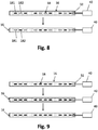
- Fig. 8 Fig. 3 is a schematic plan view of another embodiment of a lamp assembly of a vehicle body component and its operation.
- selected LEDs 18 are alternately switched on and off one after the other. First, a first selection 181 of LEDs is switched on, while a second selection 182 of LEDs 18 remains switched off. After a predetermined period of time, the first selection 181 of LEDs 18 is turned off, while the second selection 182 of LEDs 18 is turned on.
- the LEDs can be selected as desired.
- Fig. 9 is a schematic plan view of a further embodiment of an operation of a lighting arrangement.
- FIG. 9 A room pattern is implemented in the operating mode shown. Initially, only the LEDs 18 placed on the outside of the lighting arrangement 16 are switched on, while the remaining LEDs 18 remain switched off (top state of the Fig. 8 ). After a predetermined period of time, the next inner LEDs 18 on both sides are then additionally switched on, while the remaining LEDs 18 are not switched (middle state). Finally, in a final state, all LEDs 18 of the lighting arrangement 16 are switched on (lower state). Like all subsequent patterns, this pattern can be repeated over time.
- Fig. 10 is a schematic plan view of a further embodiment of an operation of a lighting arrangement.
- the operating mode shown in the light source arrangement 16 is activated by the LEDs 18 from the control device 40 switched to indicate a direction.
- the LED 18 on the left edge is switched on (uppermost state in Fig. 10 ).
- the next right LED is switched on until finally all LEDs 18 are switched on (lowest state of the Figure 10 ).
- This operating mode can thus be used, for example, as a direction indicator in addition to the direction indicators already present on the vehicle, which increases traffic safety.
- FIG. 11 Figure 3 is a schematic representation of one embodiment of a vehicle body component.
- a vehicle body component 10 designed as a radiator grille 42 is shown.
- the dashed lines indicate the locations of the radiator grille 42 at which it is conceivable to arrange the illuminant arrangement 16.
- the illuminant arrangement 16 can thus be arranged on a rib 44 of a grille 46 of the radiator grille 42 or a side wall of the radiator grille 42.
- the illuminant arrangement 16 is preferably received in a recess 14 formed at the named points of the radiator grille 44.
- the illuminant arrangement 16 received in the recess 14 is preferably covered by a cover 26 with a partially transparent section 28.
- the illuminant arrangement 16 can be arranged on at least one side wall 48 of the radiator grille 42. By arranging the illuminant arrangement 16 on a side wall 48 of the radiator grille 42, particularly effective illumination 16 of the radiator grille structure can be achieved.
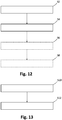
- FIG. 12 Figure 3 is a schematic representation of one embodiment of a method of manufacturing a vehicle body component.
- the method shown for producing a body component 10 includes the step of providing (S2) a base body 12 which is designed to accommodate a lighting means arrangement 16.
- a lighting device arrangement 16 which is designed as an LED strip which is bendable at least in its longitudinal direction and which has a plurality of LEDs 18 arranged one after the other and electrically connected, is fastened S4 in the base body 12.
- S6 a cover 26 for covering the recess 14 in the base body 12, the cover having at least one at least partially transparent section 28.
- the optional step of switching on S8 the lighting device 16 is carried out, the light emitted by the LEDs 18 of the lighting means arrangement 16 being emitted to the outside through the at least partially transparent section 28.
- Fig. 13 is a schematic representation of an embodiment of a method for controlling a lighting arrangement of a body component.
- the method shown for controlling a lamp arrangement 16 on a vehicle includes the step of providing S10 a control device 40 for controlling a plurality of successively arranged and electrically interconnected LEDs 18 on a base body 12 of a body component 10, in particular a radiator grille 42, attached and as an at least one Illuminant arrangement 16 formed in its longitudinal direction of bendable LED strips.
- the next step comprises switching it on and off S12, or a modulation of a radiation power, of the individual LEDs 18 according to a predetermined pattern.
Landscapes
- Engineering & Computer Science (AREA)
- Mechanical Engineering (AREA)
- General Engineering & Computer Science (AREA)
- Physics & Mathematics (AREA)
- Microelectronics & Electronic Packaging (AREA)
- Optics & Photonics (AREA)
- Lighting Device Outwards From Vehicle And Optical Signal (AREA)
- Non-Portable Lighting Devices Or Systems Thereof (AREA)
Applications Claiming Priority (2)
| Application Number | Priority Date | Filing Date | Title |
|---|---|---|---|
| DE202020000304.2U DE202020000304U1 (de) | 2020-01-24 | 2020-01-24 | Fahrzeug-Karosseriebauteil |
| US16/774,148 US11332066B2 (en) | 2020-01-24 | 2020-01-28 | Vehicle body component, method for manufacturing a vehicle body component and method for operating a lighting means arrangement |
Publications (1)
| Publication Number | Publication Date |
|---|---|
| EP3854633A1 true EP3854633A1 (fr) | 2021-07-28 |
Family
ID=74191545
Family Applications (1)
| Application Number | Title | Priority Date | Filing Date |
|---|---|---|---|
| EP21152212.3A Withdrawn EP3854633A1 (fr) | 2020-01-24 | 2021-01-19 | Composant de carrosserie de véhicule et procédé de fabrication d'un composant de carrosserie de véhicule et procédé de commande d'un agencement de moyen d'éclairage |
Country Status (1)
| Country | Link |
|---|---|
| EP (1) | EP3854633A1 (fr) |
Citations (7)
| Publication number | Priority date | Publication date | Assignee | Title |
|---|---|---|---|---|
| JP2008179225A (ja) * | 2007-01-24 | 2008-08-07 | Autech Japan Inc | ビレット構造 |
| GB2517736A (en) * | 2013-08-30 | 2015-03-04 | Prabjot Bambra | Vehicle illumination method |
| EP2993384A1 (fr) | 2014-07-11 | 2016-03-09 | vosla GmbH | Dispositif d'eclairage en forme de bande, lampe et procede de fabrication de dispositif d'eclairage en forme de bande |
| DE102017101420A1 (de) * | 2016-01-26 | 2017-07-27 | Ford Global Technologies, Llc | Lumineszierendes fahrzeugformteil |
| US20180163942A1 (en) * | 2016-12-14 | 2018-06-14 | Ford Global Technologies, Llc | Vehicle lighting assembly |
| US10281113B1 (en) * | 2018-03-05 | 2019-05-07 | Ford Global Technologies, Llc | Vehicle grille |
| US20190331311A1 (en) * | 2018-04-26 | 2019-10-31 | Lumileds Holding B.V. | Flexible led lighting strip with slanted leds |
-
2021
- 2021-01-19 EP EP21152212.3A patent/EP3854633A1/fr not_active Withdrawn
Patent Citations (7)
| Publication number | Priority date | Publication date | Assignee | Title |
|---|---|---|---|---|
| JP2008179225A (ja) * | 2007-01-24 | 2008-08-07 | Autech Japan Inc | ビレット構造 |
| GB2517736A (en) * | 2013-08-30 | 2015-03-04 | Prabjot Bambra | Vehicle illumination method |
| EP2993384A1 (fr) | 2014-07-11 | 2016-03-09 | vosla GmbH | Dispositif d'eclairage en forme de bande, lampe et procede de fabrication de dispositif d'eclairage en forme de bande |
| DE102017101420A1 (de) * | 2016-01-26 | 2017-07-27 | Ford Global Technologies, Llc | Lumineszierendes fahrzeugformteil |
| US20180163942A1 (en) * | 2016-12-14 | 2018-06-14 | Ford Global Technologies, Llc | Vehicle lighting assembly |
| US10281113B1 (en) * | 2018-03-05 | 2019-05-07 | Ford Global Technologies, Llc | Vehicle grille |
| US20190331311A1 (en) * | 2018-04-26 | 2019-10-31 | Lumileds Holding B.V. | Flexible led lighting strip with slanted leds |
Similar Documents
| Publication | Publication Date | Title |
|---|---|---|
| DE4101418C2 (de) | Schalterbetätigte Warnleuchte zur Verwendung bei Fahrzeugen | |
| EP3538812B1 (fr) | Dispositif d'éclairage, notamment pour véhicule automobile | |
| EP2762361B1 (fr) | Unité d'éclairage | |
| EP3825601A1 (fr) | Élément lumineux pour un véhicule automobile et véhicule automobile | |
| EP2151899A2 (fr) | Système de bande lumineuse | |
| DE202020000304U1 (de) | Fahrzeug-Karosseriebauteil | |
| WO2009129947A1 (fr) | Dispositif à plaque multicouche et à diodes électroluminescents | |
| DE102018009248A1 (de) | Leuchte für ein Kraftfahrzeug | |
| DE102017208999B4 (de) | Beleuchtungsvorrichtung mit einem im Querschnitt G-artig ausgebildeten und im Querschnitt aus zwei jeweils einseitig geöffneten Profilen gebildeten Gehäuse zur Beleuchtung des Innenraums eines Kraftfahrzeugs | |
| EP3788298B1 (fr) | Module d'éclairage de véhicule à moteur | |
| DE102012221639A1 (de) | Anzeigevorrichtung, Verfahren zum Darstellen einer Balkenanzeige und Verfahren zum Herstellen einer Anzeigevorrichtung | |
| DE102004018695A1 (de) | Außenrückblickspiegel für Fahrzeuge, vorzugsweise Kraftfahrzeuge | |
| DE102017120244A1 (de) | Zusatzbremsleuchte für Fahrzeuge | |
| EP1859995A2 (fr) | Rétroviseur d'un véhicule | |
| EP3466756B1 (fr) | Conduit de lumière en cascade pouvant être animé | |
| DE102018004981B4 (de) | Leuchte für ein elektrisches Haushaltsgerät | |
| EP1514731A2 (fr) | Feu de véhicule | |
| EP3814172B1 (fr) | Procédé de fabrication d'un module de clignotant ainsi que module de clignotant, système de rétroviseur et véhicule automobile | |
| EP3854633A1 (fr) | Composant de carrosserie de véhicule et procédé de fabrication d'un composant de carrosserie de véhicule et procédé de commande d'un agencement de moyen d'éclairage | |
| DE102019134630A1 (de) | Beleuchtbares Bauteil einer Innenraumverkleidung und Kraftfahrzeug | |
| DE102018215988A1 (de) | Lichtmodul, insbesondere zur Verwendung in einer Beleuchtungsvorrichtung für ein Kraftfahrzeug | |
| EP2747060B1 (fr) | Éclairage de signalisation | |
| EP0580082B1 (fr) | Dispositif optoélectronique | |
| DE102008004483A1 (de) | Flexible Leuchtmittelbaugruppe für Fahrzeugleuchten | |
| EP2783916A1 (fr) | Platine, dispositif d'affichage et rétroviseur |
Legal Events
| Date | Code | Title | Description |
|---|---|---|---|
| PUAI | Public reference made under article 153(3) epc to a published international application that has entered the european phase |
Free format text: ORIGINAL CODE: 0009012 |
|
| STAA | Information on the status of an ep patent application or granted ep patent |
Free format text: STATUS: THE APPLICATION HAS BEEN PUBLISHED |
|
| AK | Designated contracting states |
Kind code of ref document: A1 Designated state(s): AL AT BE BG CH CY CZ DE DK EE ES FI FR GB GR HR HU IE IS IT LI LT LU LV MC MK MT NL NO PL PT RO RS SE SI SK SM TR |
|
| STAA | Information on the status of an ep patent application or granted ep patent |
Free format text: STATUS: REQUEST FOR EXAMINATION WAS MADE |
|
| 17P | Request for examination filed |
Effective date: 20220118 |
|
| RBV | Designated contracting states (corrected) |
Designated state(s): AL AT BE BG CH CY CZ DE DK EE ES FI FR GB GR HR HU IE IS IT LI LT LU LV MC MK MT NL NO PL PT RO RS SE SI SK SM TR |
|
| STAA | Information on the status of an ep patent application or granted ep patent |
Free format text: STATUS: EXAMINATION IS IN PROGRESS |
|
| 17Q | First examination report despatched |
Effective date: 20231010 |
|
| STAA | Information on the status of an ep patent application or granted ep patent |
Free format text: STATUS: THE APPLICATION IS DEEMED TO BE WITHDRAWN |
|
| 18D | Application deemed to be withdrawn |
Effective date: 20250801 |