EP3854675A1 - Propulseur sous-marin - Google Patents
Propulseur sous-marin Download PDFInfo
- Publication number
- EP3854675A1 EP3854675A1 EP19875966.4A EP19875966A EP3854675A1 EP 3854675 A1 EP3854675 A1 EP 3854675A1 EP 19875966 A EP19875966 A EP 19875966A EP 3854675 A1 EP3854675 A1 EP 3854675A1
- Authority
- EP
- European Patent Office
- Prior art keywords
- water inlet
- water
- water outlet
- underwater thruster
- propeller
- Prior art date
- Legal status (The legal status is an assumption and is not a legal conclusion. Google has not performed a legal analysis and makes no representation as to the accuracy of the status listed.)
- Granted
Links
Images

Classifications
-
- B—PERFORMING OPERATIONS; TRANSPORTING
- B63—SHIPS OR OTHER WATERBORNE VESSELS; RELATED EQUIPMENT
- B63C—LAUNCHING, HAULING-OUT, OR DRY-DOCKING OF VESSELS; LIFE-SAVING IN WATER; EQUIPMENT FOR DWELLING OR WORKING UNDER WATER; MEANS FOR SALVAGING OR SEARCHING FOR UNDERWATER OBJECTS
- B63C11/00—Equipment for dwelling or working underwater; Means for searching for underwater objects
- B63C11/02—Divers' equipment
-
- B—PERFORMING OPERATIONS; TRANSPORTING
- B63—SHIPS OR OTHER WATERBORNE VESSELS; RELATED EQUIPMENT
- B63H—MARINE PROPULSION OR STEERING
- B63H11/00—Marine propulsion by water jets
- B63H11/02—Marine propulsion by water jets the propulsive medium being ambient water
- B63H11/10—Marine propulsion by water jets the propulsive medium being ambient water having means for deflecting jet or influencing cross-section thereof
- B63H11/103—Marine propulsion by water jets the propulsive medium being ambient water having means for deflecting jet or influencing cross-section thereof having means to increase efficiency of propulsive fluid, e.g. discharge pipe provided with means to improve the fluid flow
-
- B—PERFORMING OPERATIONS; TRANSPORTING
- B63—SHIPS OR OTHER WATERBORNE VESSELS; RELATED EQUIPMENT
- B63H—MARINE PROPULSION OR STEERING
- B63H11/00—Marine propulsion by water jets
- B63H11/02—Marine propulsion by water jets the propulsive medium being ambient water
- B63H11/04—Marine propulsion by water jets the propulsive medium being ambient water by means of pumps
- B63H11/08—Marine propulsion by water jets the propulsive medium being ambient water by means of pumps of rotary type
-
- B—PERFORMING OPERATIONS; TRANSPORTING
- B60—VEHICLES IN GENERAL
- B60L—PROPULSION OF ELECTRICALLY-PROPELLED VEHICLES; SUPPLYING ELECTRIC POWER FOR AUXILIARY EQUIPMENT OF ELECTRICALLY-PROPELLED VEHICLES; ELECTRODYNAMIC BRAKE SYSTEMS FOR VEHICLES IN GENERAL; MAGNETIC SUSPENSION OR LEVITATION FOR VEHICLES; MONITORING OPERATING VARIABLES OF ELECTRICALLY-PROPELLED VEHICLES; ELECTRIC SAFETY DEVICES FOR ELECTRICALLY-PROPELLED VEHICLES
- B60L15/00—Methods, circuits, or devices for controlling the traction-motor speed of electrically-propelled vehicles
- B60L15/20—Methods, circuits, or devices for controlling the traction-motor speed of electrically-propelled vehicles for control of the vehicle or its driving motor to achieve a desired performance, e.g. speed, torque, programmed variation of speed
-
- B—PERFORMING OPERATIONS; TRANSPORTING
- B60—VEHICLES IN GENERAL
- B60L—PROPULSION OF ELECTRICALLY-PROPELLED VEHICLES; SUPPLYING ELECTRIC POWER FOR AUXILIARY EQUIPMENT OF ELECTRICALLY-PROPELLED VEHICLES; ELECTRODYNAMIC BRAKE SYSTEMS FOR VEHICLES IN GENERAL; MAGNETIC SUSPENSION OR LEVITATION FOR VEHICLES; MONITORING OPERATING VARIABLES OF ELECTRICALLY-PROPELLED VEHICLES; ELECTRIC SAFETY DEVICES FOR ELECTRICALLY-PROPELLED VEHICLES
- B60L50/00—Electric propulsion with power supplied within the vehicle
- B60L50/50—Electric propulsion with power supplied within the vehicle using propulsion power supplied by batteries or fuel cells
- B60L50/60—Electric propulsion with power supplied within the vehicle using propulsion power supplied by batteries or fuel cells using power supplied by batteries
-
- B—PERFORMING OPERATIONS; TRANSPORTING
- B63—SHIPS OR OTHER WATERBORNE VESSELS; RELATED EQUIPMENT
- B63H—MARINE PROPULSION OR STEERING
- B63H1/00—Propulsive elements directly acting on water
- B63H1/02—Propulsive elements directly acting on water of rotary type
- B63H1/12—Propulsive elements directly acting on water of rotary type with rotation axis substantially in propulsive direction
- B63H1/14—Propellers
-
- B—PERFORMING OPERATIONS; TRANSPORTING
- B63—SHIPS OR OTHER WATERBORNE VESSELS; RELATED EQUIPMENT
- B63H—MARINE PROPULSION OR STEERING
- B63H21/00—Use of propulsion power plant or units on vessels
- B63H21/21—Control means for engine or transmission, specially adapted for use on marine vessels
-
- B—PERFORMING OPERATIONS; TRANSPORTING
- B63—SHIPS OR OTHER WATERBORNE VESSELS; RELATED EQUIPMENT
- B63C—LAUNCHING, HAULING-OUT, OR DRY-DOCKING OF VESSELS; LIFE-SAVING IN WATER; EQUIPMENT FOR DWELLING OR WORKING UNDER WATER; MEANS FOR SALVAGING OR SEARCHING FOR UNDERWATER OBJECTS
- B63C11/00—Equipment for dwelling or working underwater; Means for searching for underwater objects
- B63C11/02—Divers' equipment
- B63C2011/028—Devices for underwater towing of divers or divers' sleds
-
- B—PERFORMING OPERATIONS; TRANSPORTING
- B63—SHIPS OR OTHER WATERBORNE VESSELS; RELATED EQUIPMENT
- B63H—MARINE PROPULSION OR STEERING
- B63H11/00—Marine propulsion by water jets
- B63H11/02—Marine propulsion by water jets the propulsive medium being ambient water
- B63H11/04—Marine propulsion by water jets the propulsive medium being ambient water by means of pumps
- B63H11/08—Marine propulsion by water jets the propulsive medium being ambient water by means of pumps of rotary type
- B63H2011/081—Marine propulsion by water jets the propulsive medium being ambient water by means of pumps of rotary type with axial flow, i.e. the axis of rotation being parallel to the flow direction
-
- Y—GENERAL TAGGING OF NEW TECHNOLOGICAL DEVELOPMENTS; GENERAL TAGGING OF CROSS-SECTIONAL TECHNOLOGIES SPANNING OVER SEVERAL SECTIONS OF THE IPC; TECHNICAL SUBJECTS COVERED BY FORMER USPC CROSS-REFERENCE ART COLLECTIONS [XRACs] AND DIGESTS
- Y02—TECHNOLOGIES OR APPLICATIONS FOR MITIGATION OR ADAPTATION AGAINST CLIMATE CHANGE
- Y02T—CLIMATE CHANGE MITIGATION TECHNOLOGIES RELATED TO TRANSPORTATION
- Y02T10/00—Road transport of goods or passengers
- Y02T10/60—Other road transportation technologies with climate change mitigation effect
- Y02T10/70—Energy storage systems for electromobility, e.g. batteries
-
- Y—GENERAL TAGGING OF NEW TECHNOLOGICAL DEVELOPMENTS; GENERAL TAGGING OF CROSS-SECTIONAL TECHNOLOGIES SPANNING OVER SEVERAL SECTIONS OF THE IPC; TECHNICAL SUBJECTS COVERED BY FORMER USPC CROSS-REFERENCE ART COLLECTIONS [XRACs] AND DIGESTS
- Y02—TECHNOLOGIES OR APPLICATIONS FOR MITIGATION OR ADAPTATION AGAINST CLIMATE CHANGE
- Y02T—CLIMATE CHANGE MITIGATION TECHNOLOGIES RELATED TO TRANSPORTATION
- Y02T10/00—Road transport of goods or passengers
- Y02T10/60—Other road transportation technologies with climate change mitigation effect
- Y02T10/72—Electric energy management in electromobility
Definitions
- the present disclosure relates to the field of water sports equipment, in particular to an underwater thruster.
- Underwater thrusters also known as frogman thrusters, are one of important assisting means for frogmen or swimming enthusiasts in shallow water diving, and are increasingly favored by users abroad.
- An underwater thruster includes a storage battery, a controller, a driving motor and a transmission device.
- the controller controls the power supply to be turned on.
- the storage battery supplies power to the driving motor.
- the driving motor drives a propeller through the transmission device, and the propeller rotates to push the underwater thruster to advance.
- Chinese patent CN107472484A discloses an underwater thruster including an impeller, a housing, an inner cavity and a driving device, wherein the housing is cylindrical, a lower end of the housing being of a streamlined structure which has two ends communicated with each other and is hollow inside, elongate water inlets being formed at the outer side of the lower end of the housing, and the impeller being provided inside the housing near a water outlet at the bottom; the driving device is provided in the inner cavity, and a driving shaft of the driving device extends out of the inner cavity and is fixedly connected to the impeller; and a fixing means is further provided on a side of the housing.
- the patent has an integrated design in which a propeller is hidden in a pipe to avoid a risk of injury to some degree, and the user can carry around the thruster and use it at any time.
- the underwater thruster in the existing art has a poor guiding effect when in use, and is limited in the kinetic energy utilization rate.
- a problem to be solved by the present disclosure is to improve the guide stability of the underwater thruster in use and increase the kinetic energy utilization rate by improving the structure of the underwater thruster.
- an underwater thruster including a power part and a propeller, wherein the power part is provided at the upstream of the propeller to drive the propeller to rotate, the underwater thruster further comprising:
- the underwater thruster further comprising a diversion part, which is provided between the water inlet part and the water outlet part and is connected with the water inlet part and the water outlet part respectively in a plug-in manner, to uniformly disperse water entering the water inlet part to blades of the propeller, the diversion part comprising:
- an included angle between the guide pieces and a central axis of the underwater thruster is in a range of 10-15°, and an opening direction of the included angle is same as a rotating direction of the blades of the propeller.
- the other end of the water outlet part is correspondingly connected with the other end of the water inlet part.
- the water inlet part extends from the one end to the other end of the water inlet part in an arc or straight line along a central axis direction of the underwater thruster.
- the propeller is provided between the water inlet and the water outlet, and the power part is configured to drive the propeller to rotate, to discharge water in the water inlet part through the water outlet and at the same time suck water from the water inlet.
- a plurality of grilles are provided inside the water outlet part to guide high-speed rotating water into a straight line.
- the water inlet is elongate or elliptical.
- an extending direction of the water inlet is parallel to or at an included angle with respect to a central axis of the underwater thruster.
- the water outlet part is connected with the water inlet part by 1 screwing screws into screw holes.
- the diameters of radial cross-sections of the water outlet part gradually decrease from the other end to the one end of the water outlet part.
- the ratio of the diameter of the radial cross-section of the other end of the water outlet part to the diameter of the radial cross-section of the one end of the water outlet part is in a range of 1-3.
- the power part is provided inside the water inlet part, an electronic speed regulator is provided at the upstream of the power part, and a battery is provided at the upstream of the electronic speed regulator.
- the underwater thruster further comprising: a controller, which is provided at the upstream of the battery to control the on and off of the power part.
- a housing is correspondingly provided outside the battery and the controller to protect the battery and the controller, and the housing is sealed by a seal ring provided therebetween.
- a heat sink is provided between the electronic speed regulator and the housing to support the electronic speed regulator and dissipate heat generated by the electronic speed regulator; and a heat-conducting silicone grease is filled between the heat sink.
- an outer surface of the power part is provided with a heat-conducting layer to conduct and dissipate heat.
- the present disclosure provides an underwater thruster, comprising a power part and a propeller, wherein the power part is provided at the upstream of the propeller to drive the propeller to rotate.
- the underwater thruster further comprising: a water inlet part, which the power part is provided at the upstream or internally of the water inlet part, the water inlet part being provided with a water inlet, one end and the other end of the water inlet part being columnar, and the diameters of radial cross-sections of the water inlet part gradually increasing from one end to the other end of the water inlet part; and a water outlet part, which is provided at the downstream of the water inlet part, one end of the water outlet part being provided with a water outlet, wherein the water inlet part is adjacent to the propeller and provided at the upstream of the propeller, and the propeller is provided inside the water outlet part.
- diameters of radial cross-sections of the water inlet part gradually increase from one end toward the other end of the water inlet part, more water flows in different directions enter the water inlet part through the water inlet, and under the action of the propeller, water is discharged through the water outlet to generate a thrust force, thereby improving the guide stability of the underwater thruster in use, and the kinetic energy utilization rate, and effectively improving the user experience.
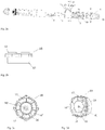
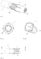
- the above drawings include the following reference signs: 1 power part; 2 propeller; 21 blade; 3 water inlet part; 31 water inlet; 4 water outlet part; 41 water outlet; 42 grille; 5 electronic speed regulator; 6 battery; 7 controller; 8 housing; 81 seal ring; ⁇ included angle; 9 charging interface; 10 diversion part; 10' axis of diversion part; 11 plug-in part; 13 one end of diversion part; 14 the other end of diversion part; 15 central disc; 16 guide piece; 16' guide channel; 17 diversion shell; 18 heat sink; 19 heat-conducting silicone grease.
- an embodiment of the present disclosure uses an advancing direction of an underwater thruster as upstream.
- an embodiment of the present disclosure provides an underwater thruster, comprising a power part 1 and a propeller 2, wherein the power part 1 is provided at the upstream of the propeller 2 to drive the propeller 2 to rotate.
- the underwater thruster further comprising: a water inlet part 3, which the power part 1 is provided at the upstream or internally of the water inlet part 3, the water inlet part 3 being provided with a water inlet 31, one end and the other end of the water inlet part 3 being columnar, and the diameter of radial cross-sections of the water inlet part 3 gradually increasing from one end to the other end of the water inlet part 3; and a water outlet part 4, the water outlet part 4 is provided at the downstream of the water inlet part 3, one end of the water outlet part 4 is provided with a water outlet 41, wherein the water inlet part 3 is adjacent to the propeller 2 and provided at the upstream of the propeller 2, and the propeller 2 is provided inside the water outlet part 4.
- diameters of radial cross-sections of the water inlet part gradually increase from one end toward the other end of the water inlet part, more water flows in different directions enter the water inlet part through the water inlet, and under the action of the propeller, water is discharged through the water outlet to generate a thrust force, thereby improving the guide stability of the underwater thruster in use, and the kinetic energy utilization rate, and effectively improving the user experience.
- An underwater thruster provided in an embodiment of the present disclosure, as shown in Fig. 2a , further comprising a diversion part 10, which is provided between the water inlet part 3 and the water outlet part 4 and is connected with the water inlet part 3 and the water outlet part 4 respectively in a plug-in manner, to uniformly disperse water entering the water inlet part 3 to blades 21 of the propeller 2.
- a diversion part 10 which is provided between the water inlet part 3 and the water outlet part 4 and is connected with the water inlet part 3 and the water outlet part 4 respectively in a plug-in manner, to uniformly disperse water entering the water inlet part 3 to blades 21 of the propeller 2.
- the other end of the water inlet part 3 is plugged to one end 13 of the diversion part
- the other end of the water outlet part 4 is plugged to the other end 14 of the diversion part to further improve the leakproofness between the water inlet part 3 and the water outlet part 4.
- the diversion part 10 includes: a diversion shell 17; a central disc 15; and a plurality of guide pieces 16, wherein the guide pieces 16 are distributed circumferentially of the diversion shell 17, and connect the diversion shell 17 and the central disc 15, with a guide channel 16' being formed between every two adjacent guide pieces.
- An included angle between the guide pieces 16 and a central axis of the underwater thruster is in a range of 10-15°, and an opening direction of the included angle is same as a rotating direction of the blades 21 of the propeller 2, so that the water entering the water inlet part 3 is uniformly distributed to the blades 21 of the propeller 2 through the guide channels 16'.
- the other end of the water outlet part 4 is correspondingly connected with the other end of the water inlet part 3, wherein the other end of the water outlet part 4 and the other end of the water inlet part 3 have same port cross-sections, and both are columnar, so that after they are connected, a water flow can be effectively prevented from flowing out from the connection therebetween.
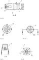
- Fig. 4a is a front view of the underwater thruster of another embodiment of the present disclosure
- Fig. 4b is a sectional view in a direction A of Fig. 4a of the underwater thruster of another embodiment of the present disclosure.
- the connection by means of the screw holes and the screws in an axial direction of the water outlet part 4 and the water inlet part 3 further strengthens the connectivity between the water outlet part 4 and the water inlet part 3 and prevents the water flow from flowing out from the connection therebetween.
- an outer edge of the other end of the water outlet part 4 may be provided with a thread, and an inner edge of the other end of the water inlet part 3 is provided with a thread, and the threads are matched to achieved connection, but embodiments of the present disclosure are not limited thereto.
- the water inlet part 3 extends from the one end to the other end of the water inlet part 3 in an arc or straight line along the axial direction.
- the water inlet part extends in an arc or straight line, so that when the underwater thruster advances underwater, the resistance during advance is effectively reduced.
- the propeller 2 is provided between the water inlet 31 and the water outlet 41, and the power part 1 such as a motor drives the propeller 2 to rotate, to discharge water in the water inlet part 3 through the water outlet 41 and at the same time suck water from the water inlet 31.
- the embodiment of the present disclosure provides the propeller 2 between the water inlet 31 and the water outlet 41, which effectively reduces a potential risk of injury of a user.
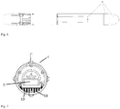
- a plurality of grilles 42 are provided inside the water outlet part 4 to guide high-speed rotating water into a straight line, so that water flows to the water outlet 41 are concentrated to generate a great thrust force.
- a plurality of grilles 42 are provided inside the water outlet part 4 to guide high-speed rotating water into a straight line.
- a central disc is further provided inside the water outlet 4, and the grilles 42 are connected between the central disc and a shell of the water outlet part 4 to maximally guide the water rotated rapidly by the propeller 2 into a straight line, so that water flows to the water outlet 41 are concentrated to generate a great thrust force.
- Embodiments of the present disclosure are not limited thereto.
- the water inlet 31 is elongate or elliptical, and a plurality of water inlets 31 are uniformly distributed circumferentially of the water inlet part 3, which is favorable for water flows in different directions to enter the water inlet part 3 through the water inlets 31.
- the shape of the water inlet 31 is not limited thereto.
- an extending direction of the water inlet 31 is parallel to or at an included angle with respect to the central axis of the underwater thruster, which may also be understood as that in the case where the water inlet part 3 extends from the one end to the other end of the water inlet part in an arc line in the axial direction, an included angle ⁇ is formed between a tangent line of the one end of the water inlet part 3 in the axial direction and a tangent line of the other end of the water inlet part 3 in the axial direction, and the included angle ⁇ is optionally 0-10°, so that water flows can enter the water inlets 31 from multiple angles during advance of the underwater thruster.
- diameters of radial cross-sections of the water outlet part 4 gradually decrease from the other end to the one end of the water outlet part 4, as shown in Figs.
- the diameter of the radial cross-section where the connection between the water inlet part 3 and the water outlet part 4 is located is the largest, and in this case, the diameter of the radial cross-section of a port of the water outlet part 4 where the water outlet 41 is located is smaller than the diameter of the radial cross-section of the other port of the water outlet part 4, which is conducive to implementing that when water flows in different directions enter the water inlet part 3 through the water inlets 31, the rotation of the propeller 2 drives more water flows to the water outlet 41, so that water flows at the water outlet are concentrated with some intensity to generate a great thrust force.
- the ratio of the diameter of the radial cross-section of the other end of the water outlet part 4 to the diameter of the radial cross-section of the one end of the water outlet part 4 is in a range of 1-3.
- the power part 1 is provided inside the water inlet part 3, an electronic speed regulator 5 is provided at the upstream of the power part 1, and a battery 6 is provided at the upstream of the electronic speed regulator 5.
- the power part 1 is a brushless motor, it needs to be connected to the battery 6 through the electronic speed regulator 5 to provide energy for the power part 3.
- An underwater thruster provided in an embodiment of the present disclosure further includes: a controller 7 such as a printed circuit board, the controller 7 being provided at the upstream of the battery 6 to control the on and off of the power part 1.
- a controller 7 such as a printed circuit board, the controller 7 being provided at the upstream of the battery 6 to control the on and off of the power part 1.
- a housing 8 is correspondingly provided outside the battery 6 and the controller 7 to protect the battery 6 and the controller 7, and as shown in Figs. 1b and 1c , the housing 7 is sealed by a seal ring 81 provided therebetween.
- a heat sink 18 is provided between the electronic speed regulator 5 and the housing 8 to support the electronic speed regulator 5 and dissipate heat generated by the electronic speed regulator 5; and a heat-conducting silicone grease 19 (a shaded part) is filled between the heat sink 18 to further dissipate the heat generated by the electronic speed regulator 5.
- an outer surface of the power part 1 is provided with a heat-conducting layer to conduct and dissipate heat generated by the power part 1.
- the underwater thruster has a waterproof function.
- the battery 6 when the controller 7 is turned on, the battery 6 provides electric energy to the power part 1, that is, the battery 6 provides electric energy to the power part 1 through the electronic speed regulator 5, and the power part 1 converts the electric energy into kinetic energy to drive a rotating shaft to rotate, and the rotating shaft drives the propeller 2 to rotate, so that water flows entering the water inlet part 3 through the water inlet 31 are introduced to the water outlet 41, and the plurality of grilles 42 are provided inside the water outlet part 4 to guide high-speed rotating water into a straight line, so that water flows to the water outlet 41 are concentrated to generate a great thrust force, which drives the underwater thruster to advance.
- the underwater thruster sucks water straight ahead and laterally ahead of it during work, and more water flows in different directions enter the water inlet part through the water inlet to generate a forward pulling force, and under the action of the propeller, water is discharged through the water outlet to generate a thrust force, so that the kinetic energy of the product is more fully and effectively used, and the user experience is effectively improved.
Landscapes
- Engineering & Computer Science (AREA)
- Mechanical Engineering (AREA)
- Ocean & Marine Engineering (AREA)
- Chemical & Material Sciences (AREA)
- Combustion & Propulsion (AREA)
- Transportation (AREA)
- Power Engineering (AREA)
- Sustainable Development (AREA)
- Sustainable Energy (AREA)
- Life Sciences & Earth Sciences (AREA)
- Physics & Mathematics (AREA)
- Fluid Mechanics (AREA)
- Other Liquid Machine Or Engine Such As Wave Power Use (AREA)
Applications Claiming Priority (2)
| Application Number | Priority Date | Filing Date | Title |
|---|---|---|---|
| CN201811236217.7A CN111086611A (zh) | 2018-10-23 | 2018-10-23 | 水下推进器 |
| PCT/CN2019/092062 WO2020082765A1 (fr) | 2018-10-23 | 2019-06-20 | Propulseur sous-marin |
Publications (3)
| Publication Number | Publication Date |
|---|---|
| EP3854675A1 true EP3854675A1 (fr) | 2021-07-28 |
| EP3854675A4 EP3854675A4 (fr) | 2021-12-01 |
| EP3854675B1 EP3854675B1 (fr) | 2025-03-05 |
Family
ID=70330386
Family Applications (1)
| Application Number | Title | Priority Date | Filing Date |
|---|---|---|---|
| EP19875966.4A Active EP3854675B1 (fr) | 2018-10-23 | 2019-06-20 | Propulseur sous-marin |
Country Status (5)
| Country | Link |
|---|---|
| US (1) | US11787521B2 (fr) |
| EP (1) | EP3854675B1 (fr) |
| CN (1) | CN111086611A (fr) |
| DK (1) | DK3854675T3 (fr) |
| WO (1) | WO2020082765A1 (fr) |
Families Citing this family (10)
| Publication number | Priority date | Publication date | Assignee | Title |
|---|---|---|---|---|
| CN112298512B (zh) * | 2020-11-11 | 2022-01-25 | 南京工程学院 | 一种水下涡轮增压快速换向推进器 |
| CN113525636A (zh) * | 2021-07-15 | 2021-10-22 | 哈尔滨工程大学 | 一种海底声呐机器人用密封外壳 |
| CN114313161A (zh) * | 2021-12-10 | 2022-04-12 | 深圳市苇渡智能科技有限公司 | 一种导流装置和潜水设备 |
| CN216611544U (zh) * | 2021-12-10 | 2022-05-27 | 深圳市苇渡智能科技有限公司 | 一种潜水推进器 |
| CN114286502B (zh) * | 2021-12-23 | 2023-09-05 | 广东逸动科技有限公司 | 控制电路板的散热结构、水下推进器及水上运载装置 |
| CN114435573B (zh) * | 2022-02-17 | 2023-05-26 | 交通运输部天津水运工程科学研究所 | 一种船用涡轮推进器 |
| KR102723195B1 (ko) * | 2022-07-27 | 2024-10-28 | 구창훈 | 수중 추진체 |
| CN116513421B (zh) * | 2023-04-14 | 2023-09-19 | 威海多鱼海洋科技有限公司 | 水下无人自主航行器 |
| CN117141699B (zh) * | 2023-10-27 | 2024-01-02 | 江苏丞工科技有限公司 | 一种多功能水面救援机器人及工作方法 |
| CN120171743A (zh) * | 2023-12-18 | 2025-06-20 | 四角兽科技有限公司 | 水下推进器的散热改良结构 |
Family Cites Families (18)
| Publication number | Priority date | Publication date | Assignee | Title |
|---|---|---|---|---|
| NL268583A (fr) * | 1960-08-25 | |||
| JPH02147495A (ja) * | 1988-11-30 | 1990-06-06 | Suzuki Motor Co Ltd | ウォータジェット推進装置のインペラ |
| JP3490134B2 (ja) * | 1994-03-11 | 2004-01-26 | 川崎重工業株式会社 | 案内羽根前置ウォータジェット推進器 |
| US20020170763A1 (en) * | 2001-05-16 | 2002-11-21 | Townsend Arthur R. | Electric scooter with selectable speed ranges |
| US7000559B2 (en) * | 2004-05-28 | 2006-02-21 | Daka Research Inc. (Br. Virg. Isl Corp.) Offshoreincorporations Centre | Modularized underwater motive device |
| CN201016028Y (zh) | 2005-06-20 | 2008-02-06 | 智点科技股份有限公司 | 喷射流体集束推进器 |
| JP5100370B2 (ja) * | 2007-12-28 | 2012-12-19 | 川崎重工業株式会社 | 推力発生装置 |
| KR20120094763A (ko) * | 2011-02-17 | 2012-08-27 | 충남대학교산학협력단 | 전류고정날개를 적용한 선박용 덕트-프로펠러 |
| CN203094426U (zh) * | 2013-01-14 | 2013-07-31 | 杭州海旅科技有限公司 | 水下喷射推进器 |
| CN107776862B (zh) | 2016-08-31 | 2020-04-14 | 柳州市向日葵科技有限公司 | 一种电动推进器 |
| CN206243426U (zh) * | 2016-12-02 | 2017-06-13 | 长兴大河造船有限公司 | 一种船舶推进器 |
| JP2018154177A (ja) * | 2017-03-16 | 2018-10-04 | ヤンマー株式会社 | 水中推進装置 |
| CN107472484A (zh) * | 2017-09-06 | 2017-12-15 | 佛山市道道电子科技有限公司 | 一种水下推进器 |
| SG11202003855RA (en) * | 2017-10-31 | 2020-05-28 | Samsung Heavy Industries Co Ltd | Apparatus for enhancing propulsion efficiency |
| CN108327883A (zh) | 2017-12-29 | 2018-07-27 | 中国船舶工业集团公司第七0八研究所 | 一种喷水推进装置轴系结构 |
| CN207725587U (zh) | 2018-01-02 | 2018-08-14 | 北京章鱼智控科技有限公司 | 一种喷水推进装置 |
| CN207945129U (zh) | 2018-03-09 | 2018-10-09 | 东莞市特浪新能源科技有限公司 | 一种喷水推进泵 |
| CN209126945U (zh) * | 2018-10-23 | 2019-07-19 | 东辉休闲运动用品(上海)有限公司 | 水下推进器 |
-
2018
- 2018-10-23 CN CN201811236217.7A patent/CN111086611A/zh active Pending
-
2019
- 2019-06-20 WO PCT/CN2019/092062 patent/WO2020082765A1/fr not_active Ceased
- 2019-06-20 EP EP19875966.4A patent/EP3854675B1/fr active Active
- 2019-06-20 DK DK19875966.4T patent/DK3854675T3/da active
- 2019-06-20 US US17/288,266 patent/US11787521B2/en active Active
Also Published As
| Publication number | Publication date |
|---|---|
| EP3854675A4 (fr) | 2021-12-01 |
| WO2020082765A1 (fr) | 2020-04-30 |
| EP3854675B1 (fr) | 2025-03-05 |
| CN111086611A (zh) | 2020-05-01 |
| US20210380211A1 (en) | 2021-12-09 |
| US11787521B2 (en) | 2023-10-17 |
| DK3854675T3 (da) | 2025-06-10 |
Similar Documents
| Publication | Publication Date | Title |
|---|---|---|
| US11787521B2 (en) | Underwater thruster | |
| EP2493754B1 (fr) | Planche motorisée pour sports nautiques | |
| CN210478964U (zh) | 一种电动冲浪板的推进系统及具有其的电动冲浪板 | |
| CN210478965U (zh) | 一种冷却系统组件及具有其的水上冲浪板 | |
| US10882593B1 (en) | Peller blade with a flap | |
| CN110697014A (zh) | 无轴泵喷矢量推进装置 | |
| JP2009090961A (ja) | ポッド型推進器及びポッド型ポンプ装置 | |
| CN210681072U (zh) | 一种电动鱼鳍及水运工具 | |
| CN214190053U (zh) | 推进器及潜水器 | |
| CN209126945U (zh) | 水下推进器 | |
| CN210653565U (zh) | 一种电动鱼鳍及水运工具 | |
| CN210707837U (zh) | 一种泵喷推进器 | |
| CN211196565U (zh) | 一种可穿戴的潜水推进装置 | |
| CN210212739U (zh) | 水下推进器 | |
| CN210734443U (zh) | 一种电源盒 | |
| CN211918966U (zh) | 一种用于水下助推器的动力涵道 | |
| CN112298470A (zh) | 一种电动鱼鳍及水运工具 | |
| CN218662333U (zh) | 一种水下推进器 | |
| CN223494741U (zh) | 一种水下推进器 | |
| CN112298469A (zh) | 一种电动鱼鳍及水运工具 | |
| CN215663891U (zh) | 一种双侧入水的鳍状推进器 | |
| CN209351573U (zh) | 水下推进器 | |
| CN107685845B (zh) | 一种组装式水下推进设备 | |
| CN112076457A (zh) | 一种无边际泳池 | |
| CN217682441U (zh) | 导流扩压结构及具有其的洗涤泵、洗涤电器 |
Legal Events
| Date | Code | Title | Description |
|---|---|---|---|
| STAA | Information on the status of an ep patent application or granted ep patent |
Free format text: STATUS: THE INTERNATIONAL PUBLICATION HAS BEEN MADE |
|
| PUAI | Public reference made under article 153(3) epc to a published international application that has entered the european phase |
Free format text: ORIGINAL CODE: 0009012 |
|
| STAA | Information on the status of an ep patent application or granted ep patent |
Free format text: STATUS: REQUEST FOR EXAMINATION WAS MADE |
|
| 17P | Request for examination filed |
Effective date: 20210423 |
|
| AK | Designated contracting states |
Kind code of ref document: A1 Designated state(s): AL AT BE BG CH CY CZ DE DK EE ES FI FR GB GR HR HU IE IS IT LI LT LU LV MC MK MT NL NO PL PT RO RS SE SI SK SM TR |
|
| REG | Reference to a national code |
Ref country code: DE Ref legal event code: R079 Free format text: PREVIOUS MAIN CLASS: B63H0011020000 Ipc: B63H0011080000 Ref document number: 602019067025 Country of ref document: DE |
|
| A4 | Supplementary search report drawn up and despatched |
Effective date: 20211103 |
|
| RIC1 | Information provided on ipc code assigned before grant |
Ipc: B63C 11/02 20060101ALN20211027BHEP Ipc: B63H 11/103 20060101ALI20211027BHEP Ipc: B63H 11/08 20060101AFI20211027BHEP |
|
| DAV | Request for validation of the european patent (deleted) | ||
| DAX | Request for extension of the european patent (deleted) | ||
| GRAP | Despatch of communication of intention to grant a patent |
Free format text: ORIGINAL CODE: EPIDOSNIGR1 |
|
| STAA | Information on the status of an ep patent application or granted ep patent |
Free format text: STATUS: GRANT OF PATENT IS INTENDED |
|
| INTG | Intention to grant announced |
Effective date: 20241217 |
|
| GRAS | Grant fee paid |
Free format text: ORIGINAL CODE: EPIDOSNIGR3 |
|
| GRAA | (expected) grant |
Free format text: ORIGINAL CODE: 0009210 |
|
| STAA | Information on the status of an ep patent application or granted ep patent |
Free format text: STATUS: THE PATENT HAS BEEN GRANTED |
|
| AK | Designated contracting states |
Kind code of ref document: B1 Designated state(s): AL AT BE BG CH CY CZ DE DK EE ES FI FR GB GR HR HU IE IS IT LI LT LU LV MC MK MT NL NO PL PT RO RS SE SI SK SM TR |
|
| REG | Reference to a national code |
Ref country code: GB Ref legal event code: FG4D |
|
| REG | Reference to a national code |
Ref country code: CH Ref legal event code: EP |
|
| REG | Reference to a national code |
Ref country code: IE Ref legal event code: FG4D |
|
| REG | Reference to a national code |
Ref country code: DE Ref legal event code: R096 Ref document number: 602019067025 Country of ref document: DE |
|
| P01 | Opt-out of the competence of the unified patent court (upc) registered |
Free format text: CASE NUMBER: APP_13064/2025 Effective date: 20250317 |
|
| REG | Reference to a national code |
Ref country code: DK Ref legal event code: T3 Effective date: 20250603 |
|
| PG25 | Lapsed in a contracting state [announced via postgrant information from national office to epo] |
Ref country code: RS Free format text: LAPSE BECAUSE OF FAILURE TO SUBMIT A TRANSLATION OF THE DESCRIPTION OR TO PAY THE FEE WITHIN THE PRESCRIBED TIME-LIMIT Effective date: 20250605 |
|
| PG25 | Lapsed in a contracting state [announced via postgrant information from national office to epo] |
Ref country code: FI Free format text: LAPSE BECAUSE OF FAILURE TO SUBMIT A TRANSLATION OF THE DESCRIPTION OR TO PAY THE FEE WITHIN THE PRESCRIBED TIME-LIMIT Effective date: 20250305 |
|
| PGFP | Annual fee paid to national office [announced via postgrant information from national office to epo] |
Ref country code: DE Payment date: 20250617 Year of fee payment: 7 |
|
| REG | Reference to a national code |
Ref country code: NL Ref legal event code: MP Effective date: 20250305 |
|
| PG25 | Lapsed in a contracting state [announced via postgrant information from national office to epo] |
Ref country code: ES Free format text: LAPSE BECAUSE OF FAILURE TO SUBMIT A TRANSLATION OF THE DESCRIPTION OR TO PAY THE FEE WITHIN THE PRESCRIBED TIME-LIMIT Effective date: 20250305 |
|
| PGFP | Annual fee paid to national office [announced via postgrant information from national office to epo] |
Ref country code: GB Payment date: 20250625 Year of fee payment: 7 Ref country code: DK Payment date: 20250627 Year of fee payment: 7 |
|
| REG | Reference to a national code |
Ref country code: LT Ref legal event code: MG9D |
|
| PG25 | Lapsed in a contracting state [announced via postgrant information from national office to epo] |
Ref country code: NO Free format text: LAPSE BECAUSE OF FAILURE TO SUBMIT A TRANSLATION OF THE DESCRIPTION OR TO PAY THE FEE WITHIN THE PRESCRIBED TIME-LIMIT Effective date: 20250605 |
|
| PG25 | Lapsed in a contracting state [announced via postgrant information from national office to epo] |
Ref country code: HR Free format text: LAPSE BECAUSE OF FAILURE TO SUBMIT A TRANSLATION OF THE DESCRIPTION OR TO PAY THE FEE WITHIN THE PRESCRIBED TIME-LIMIT Effective date: 20250305 |
|
| PG25 | Lapsed in a contracting state [announced via postgrant information from national office to epo] |
Ref country code: LV Free format text: LAPSE BECAUSE OF FAILURE TO SUBMIT A TRANSLATION OF THE DESCRIPTION OR TO PAY THE FEE WITHIN THE PRESCRIBED TIME-LIMIT Effective date: 20250305 |
|
| PGFP | Annual fee paid to national office [announced via postgrant information from national office to epo] |
Ref country code: FR Payment date: 20250630 Year of fee payment: 7 |
|
| PG25 | Lapsed in a contracting state [announced via postgrant information from national office to epo] |
Ref country code: BG Free format text: LAPSE BECAUSE OF FAILURE TO SUBMIT A TRANSLATION OF THE DESCRIPTION OR TO PAY THE FEE WITHIN THE PRESCRIBED TIME-LIMIT Effective date: 20250305 Ref country code: GR Free format text: LAPSE BECAUSE OF FAILURE TO SUBMIT A TRANSLATION OF THE DESCRIPTION OR TO PAY THE FEE WITHIN THE PRESCRIBED TIME-LIMIT Effective date: 20250606 |
|
| PGFP | Annual fee paid to national office [announced via postgrant information from national office to epo] |
Ref country code: CZ Payment date: 20250616 Year of fee payment: 7 |
|
| REG | Reference to a national code |
Ref country code: AT Ref legal event code: MK05 Ref document number: 1772750 Country of ref document: AT Kind code of ref document: T Effective date: 20250305 |
|
| PG25 | Lapsed in a contracting state [announced via postgrant information from national office to epo] |
Ref country code: NL Free format text: LAPSE BECAUSE OF FAILURE TO SUBMIT A TRANSLATION OF THE DESCRIPTION OR TO PAY THE FEE WITHIN THE PRESCRIBED TIME-LIMIT Effective date: 20250305 |
|
| PG25 | Lapsed in a contracting state [announced via postgrant information from national office to epo] |
Ref country code: SE Free format text: LAPSE BECAUSE OF FAILURE TO SUBMIT A TRANSLATION OF THE DESCRIPTION OR TO PAY THE FEE WITHIN THE PRESCRIBED TIME-LIMIT Effective date: 20250305 |
|
| PG25 | Lapsed in a contracting state [announced via postgrant information from national office to epo] |
Ref country code: SM Free format text: LAPSE BECAUSE OF FAILURE TO SUBMIT A TRANSLATION OF THE DESCRIPTION OR TO PAY THE FEE WITHIN THE PRESCRIBED TIME-LIMIT Effective date: 20250305 |
|
| PG25 | Lapsed in a contracting state [announced via postgrant information from national office to epo] |
Ref country code: PT Free format text: LAPSE BECAUSE OF FAILURE TO SUBMIT A TRANSLATION OF THE DESCRIPTION OR TO PAY THE FEE WITHIN THE PRESCRIBED TIME-LIMIT Effective date: 20250707 |
|
| PG25 | Lapsed in a contracting state [announced via postgrant information from national office to epo] |
Ref country code: IT Free format text: LAPSE BECAUSE OF FAILURE TO SUBMIT A TRANSLATION OF THE DESCRIPTION OR TO PAY THE FEE WITHIN THE PRESCRIBED TIME-LIMIT Effective date: 20250305 Ref country code: PL Free format text: LAPSE BECAUSE OF FAILURE TO SUBMIT A TRANSLATION OF THE DESCRIPTION OR TO PAY THE FEE WITHIN THE PRESCRIBED TIME-LIMIT Effective date: 20250305 |
|
| PG25 | Lapsed in a contracting state [announced via postgrant information from national office to epo] |
Ref country code: AT Free format text: LAPSE BECAUSE OF FAILURE TO SUBMIT A TRANSLATION OF THE DESCRIPTION OR TO PAY THE FEE WITHIN THE PRESCRIBED TIME-LIMIT Effective date: 20250305 |
|
| PG25 | Lapsed in a contracting state [announced via postgrant information from national office to epo] |
Ref country code: EE Free format text: LAPSE BECAUSE OF FAILURE TO SUBMIT A TRANSLATION OF THE DESCRIPTION OR TO PAY THE FEE WITHIN THE PRESCRIBED TIME-LIMIT Effective date: 20250305 |
|
| PG25 | Lapsed in a contracting state [announced via postgrant information from national office to epo] |
Ref country code: RO Free format text: LAPSE BECAUSE OF FAILURE TO SUBMIT A TRANSLATION OF THE DESCRIPTION OR TO PAY THE FEE WITHIN THE PRESCRIBED TIME-LIMIT Effective date: 20250305 |
|
| PG25 | Lapsed in a contracting state [announced via postgrant information from national office to epo] |
Ref country code: SK Free format text: LAPSE BECAUSE OF FAILURE TO SUBMIT A TRANSLATION OF THE DESCRIPTION OR TO PAY THE FEE WITHIN THE PRESCRIBED TIME-LIMIT Effective date: 20250305 |
|
| PG25 | Lapsed in a contracting state [announced via postgrant information from national office to epo] |
Ref country code: IS Free format text: LAPSE BECAUSE OF FAILURE TO SUBMIT A TRANSLATION OF THE DESCRIPTION OR TO PAY THE FEE WITHIN THE PRESCRIBED TIME-LIMIT Effective date: 20250705 |
|
| REG | Reference to a national code |
Ref country code: DE Ref legal event code: R097 Ref document number: 602019067025 Country of ref document: DE |
|
| PLBE | No opposition filed within time limit |
Free format text: ORIGINAL CODE: 0009261 |
|
| STAA | Information on the status of an ep patent application or granted ep patent |
Free format text: STATUS: NO OPPOSITION FILED WITHIN TIME LIMIT |
|
| REG | Reference to a national code |
Ref country code: CH Ref legal event code: L10 Free format text: ST27 STATUS EVENT CODE: U-0-0-L10-L00 (AS PROVIDED BY THE NATIONAL OFFICE) Effective date: 20260114 |
|
| REG | Reference to a national code |
Ref country code: CH Ref legal event code: H13 Free format text: ST27 STATUS EVENT CODE: U-0-0-H10-H13 (AS PROVIDED BY THE NATIONAL OFFICE) Effective date: 20260127 |
|
| PG25 | Lapsed in a contracting state [announced via postgrant information from national office to epo] |
Ref country code: MC Free format text: LAPSE BECAUSE OF FAILURE TO SUBMIT A TRANSLATION OF THE DESCRIPTION OR TO PAY THE FEE WITHIN THE PRESCRIBED TIME-LIMIT Effective date: 20250305 |
|
| 26N | No opposition filed |
Effective date: 20251208 |
|
| PG25 | Lapsed in a contracting state [announced via postgrant information from national office to epo] |
Ref country code: LU Free format text: LAPSE BECAUSE OF NON-PAYMENT OF DUE FEES Effective date: 20250620 |
|
| REG | Reference to a national code |
Ref country code: BE Ref legal event code: MM Effective date: 20250630 |
|
| PG25 | Lapsed in a contracting state [announced via postgrant information from national office to epo] |
Ref country code: IE Free format text: LAPSE BECAUSE OF NON-PAYMENT OF DUE FEES Effective date: 20250620 |
|
| PG25 | Lapsed in a contracting state [announced via postgrant information from national office to epo] |
Ref country code: BE Free format text: LAPSE BECAUSE OF NON-PAYMENT OF DUE FEES Effective date: 20250630 |
|
| PG25 | Lapsed in a contracting state [announced via postgrant information from national office to epo] |
Ref country code: CH Free format text: LAPSE BECAUSE OF NON-PAYMENT OF DUE FEES Effective date: 20250630 |