EP3854718A1 - Stapelbares lagersystem - Google Patents
Stapelbares lagersystem Download PDFInfo
- Publication number
- EP3854718A1 EP3854718A1 EP21152606.6A EP21152606A EP3854718A1 EP 3854718 A1 EP3854718 A1 EP 3854718A1 EP 21152606 A EP21152606 A EP 21152606A EP 3854718 A1 EP3854718 A1 EP 3854718A1
- Authority
- EP
- European Patent Office
- Prior art keywords
- container
- latch
- stacking direction
- coupler
- coupling portion
- Prior art date
- Legal status (The legal status is an assumption and is not a legal conclusion. Google has not performed a legal analysis and makes no representation as to the accuracy of the status listed.)
- Pending
Links
Images




Classifications
-
- B—PERFORMING OPERATIONS; TRANSPORTING
- B65—CONVEYING; PACKING; STORING; HANDLING THIN OR FILAMENTARY MATERIAL
- B65D—CONTAINERS FOR STORAGE OR TRANSPORT OF ARTICLES OR MATERIALS, e.g. BAGS, BARRELS, BOTTLES, BOXES, CANS, CARTONS, CRATES, DRUMS, JARS, TANKS, HOPPERS, FORWARDING CONTAINERS; ACCESSORIES, CLOSURES, OR FITTINGS THEREFOR; PACKAGING ELEMENTS; PACKAGES
- B65D21/00—Nestable, stackable or joinable containers; Containers of variable capacity
- B65D21/02—Containers specially shaped, or provided with fittings or attachments, to facilitate nesting, stacking, or joining together
- B65D21/0209—Containers specially shaped, or provided with fittings or attachments, to facilitate nesting, stacking, or joining together stackable or joined together one-upon-the-other in the upright or upside-down position
- B65D21/0217—Containers with a closure presenting stacking elements
- B65D21/0223—Containers with a closure presenting stacking elements the closure and the bottom presenting local co-operating elements, e.g. projections and recesses
-
- B—PERFORMING OPERATIONS; TRANSPORTING
- B25—HAND TOOLS; PORTABLE POWER-DRIVEN TOOLS; MANIPULATORS
- B25H—WORKSHOP EQUIPMENT, e.g. FOR MARKING-OUT WORK; STORAGE MEANS FOR WORKSHOPS
- B25H3/00—Storage means or arrangements for workshops facilitating access to, or handling of, work tools or instruments
- B25H3/02—Boxes
-
- B—PERFORMING OPERATIONS; TRANSPORTING
- B65—CONVEYING; PACKING; STORING; HANDLING THIN OR FILAMENTARY MATERIAL
- B65D—CONTAINERS FOR STORAGE OR TRANSPORT OF ARTICLES OR MATERIALS, e.g. BAGS, BARRELS, BOTTLES, BOXES, CANS, CARTONS, CRATES, DRUMS, JARS, TANKS, HOPPERS, FORWARDING CONTAINERS; ACCESSORIES, CLOSURES, OR FITTINGS THEREFOR; PACKAGING ELEMENTS; PACKAGES
- B65D21/00—Nestable, stackable or joinable containers; Containers of variable capacity
- B65D21/02—Containers specially shaped, or provided with fittings or attachments, to facilitate nesting, stacking, or joining together
- B65D21/0209—Containers specially shaped, or provided with fittings or attachments, to facilitate nesting, stacking, or joining together stackable or joined together one-upon-the-other in the upright or upside-down position
- B65D21/0224—Auxiliary removable stacking elements other than covers
-
- B—PERFORMING OPERATIONS; TRANSPORTING
- B65—CONVEYING; PACKING; STORING; HANDLING THIN OR FILAMENTARY MATERIAL
- B65D—CONTAINERS FOR STORAGE OR TRANSPORT OF ARTICLES OR MATERIALS, e.g. BAGS, BARRELS, BOTTLES, BOXES, CANS, CARTONS, CRATES, DRUMS, JARS, TANKS, HOPPERS, FORWARDING CONTAINERS; ACCESSORIES, CLOSURES, OR FITTINGS THEREFOR; PACKAGING ELEMENTS; PACKAGES
- B65D43/00—Lids or covers for rigid or semi-rigid containers
- B65D43/14—Non-removable lids or covers
- B65D43/16—Non-removable lids or covers hinged for upward or downward movement
- B65D43/163—Non-removable lids or covers hinged for upward or downward movement the container and the lid being made separately
Definitions
- the present disclosure relates to storage containers and, more particularly, to storage containers that are securable to one another in a stackable configuration.
- a stackable storage system may include multiple storage containers each having a lid and base.
- the base of an upper container may be placed on the lid of a lower container, and one of the containers may include a latch mechanism.
- the latching mechanism may be operable to selectively couple and de-couple adjacent storage containers.
- a stackable storage system that includes a first container, a second container, and a latch moveable between a first position and a second position.
- the first container includes a projection extending away from the first container along a stacking direction. An edge portion extends from the projection along a plane substantially perpendicular to the stacking direction.
- the second container includes a recess extending in a direction parallel to the stacking direction. The recess receives the projection when the first container and the second container are stacked relative to one another in the stacking direction.
- the latch overlaps the edge portion with respect to the stacking direction while the latch is in the first position to secure the first container and the second container to one another.
- the latch and the edge portion are positioned in a non-overlapping manner relative to one another with respect to the stacking direction while the latch is in the second position to permit separation of the first container from the second container.
- the latch is moveable in a direction that is different from the stacking direction.
- the edge portion is a first edge portion
- the projection has a second edge portion extending along the plane substantially perpendicular to the stacking direction.
- the first edge portion and the second edge portion may extend from the projection in different directions.
- the first edge portion is oriented at a first oblique angle relative to a front surface of the first container, and the second edge portion is oriented at a second oblique angle relative to the front surface of the first container.
- the latch overlaps the first edge portion and the second edge portion along the stacking direction while in the first position.
- the projection is a first projection in a plurality of projections each extending away from the first container along the stacking direction and having the edge portion extending along the plane substantially perpendicular to the stacking direction.
- the latch overlaps the edge portion of each projection in the plurality of projections with respect to the stacking direction while in the first position.
- one of the first container and the second container further includes a tab
- the other one of the first container and the second container further includes a notch
- the tab and the notch may be complimentary to one another and configured to align the first container with the second container in a common orientation when the first container and the second container are stacked on one another in the stacking direction.
- the stackable storage system further comprises: a biasing member; and a link moveably supported on either of the first container and the second container.
- the link may be configured to physically communicate movement to the latch.
- Either of the link and the latch may be configured to receive a biasing force generated by the biasing member.
- the link is a push button configured to be pressed by a user to move the latch from the first position to the second position.
- the biasing member may be configured to urge the latch from the second position to the first position.
- the link is a handle configured to be operated by a user to move the latch from the first position to the second position.
- the biasing member may be configured to urge the latch from the second position to the first position.
- a mating interface for selectively securing a first container relative to a second container in a stacked configuration along a stacking direction.
- the mating interface includes a projection and a coupler.
- the projection is positioned on one of the first container and the second container.
- the projection is spaced apart from a surface to form a gap.
- the gap is open in a direction transverse to the stacking direction.
- the coupler is moveably mounted on the other of the first container and the second container.
- the coupler is moveable in the direction transverse to the stacking direction between a first position and a second position. In the first position, a portion of the coupler is positioned within the gap thereby preventing the first container and the second container from being separated along the stacking direction. In the second position, the coupler is not positioned within the gap.
- a tab terminates a portion of the gap such that a portion of the gap is closed along the stacking direction.
- the coupler may be configured to engage and overlap the tab with respect to the stacking direction while in the first position.
- a depth of the gap is defined between a tab and a depressed surface.
- the tab and the depressed surface may be formed on a common container with the gap.
- the coupler is disposed between the tab and the depressed surface such that the tab, the depressed surface, and the coupler overlap each another with respect to the stacking direction.
- the coupler is biased toward the first position.
- the tab may include an incline configured to engage with the coupler during stacking of the first container and the second container.
- Engagement between the coupler and the incline along the stacking direction may urge the coupler against a biasing force and away from the first position.
- the coupler engages the incline at the mating interface.
- the coupler may move in the direction transverse to the stacking direction as the first container is brought closer to the second container along the stacking direction.
- the coupler may be urged by the biasing force to the first position once the coupler passes beyond the tab along with respect to the stacking direction.
- first container and the second container stacked at the mating interface are prevented from shifting relative one another across the stacking direction while the coupler is in either of the first position and the second position.
- a storage container that includes a base, a lid pivotably coupled to the base by a hinge and selectively retained in a closed position, a plurality of pockets positioned on one of the base and the lid, a surface formed on the other of the base and the lid, and a plurality of projections.
- the plurality of pockets have sides recessed with respect to a first direction.
- Each of the plurality of pockets has a polygonal profile, at least one edge of each pocket is oriented at an oblique angle relative to a front surface of the base.
- the plurality of projections extends from the surface with respect to the first direction.
- Each of the plurality of projections has a projection profile substantially corresponding to an associated one of the plurality of pockets.
- Each of the plurality of projections is substantially aligned with the associated one of the plurality of pockets along the first direction.
- An edge portion protrudes from one of the plurality of projections in a plane substantially normal with respect to the first direction.
- the edge portion is oriented at the oblique angle relative to the front surface of the base.
- a gap is formed between the edge portion and the surface.
- a latch is moveable against a biasing force in a second direction transverse to the first direction, the latch moveable between a first position and a second position. At least a portion of the latch extends through at least one side of the plurality of pockets while the latch is in the first position.
- the latch is retracted with respect to the sides of the plurality of pockets while the latch is in the second position.
- a stackable storage system that includes a first container, a second container, and a coupler.
- the first container includes a first surface defining a first coupling portion
- the second container includes a second surface opposite the first surface defining a second coupling portion aligned with the first coupling portion.
- the coupler is disposed between the first coupling portion and the second coupling portion and is configured to move between portions of the first coupling portion and the second coupling portion to selectively lock the first container to the second container.
- the first container and the second container are toolboxes.
- the first container is stacked over the second container such that the first coupling portion is disposed around a perimeter of the second coupling portion.
- the second coupling portion is configured to be at least partially nested with the first coupling portion.
- the second coupling portion is a projection and the first coupling portion is a recess.
- the coupler is spring-biased towards a center of the first coupling portion, the second coupling portion, the first container, or the second container.
- the coupler is movably attached to at least one of the first container and the second container.
- the coupler is configured to slide through an opening formed in the first coupling portion to engage the second coupling portion thereby locking the first container to the second container.
- the first container and the second container are prevented from shifting laterally with respect to a stacking direction.
- the first coupling portion includes a plurality of recesses and the second coupling portion includes a plurality of projections, each of the plurality of projections engageable with an associated one of the plurality of recesses.
- the coupler is a unitary member being positioned between each of the plurality of projections and the associated recesses.
- FIGS. 1A and 1B illustrate a system 10 of multiple storage components or elements 14 (e.g., containers, toolboxes, and/or the like) in a stacked configuration and secured relative to one another along a stacked or stacking direction D1.
- the system 10 includes an interface 18 for mating opposite and optionally complementary surfaces of the storage containers 14 relative to one another.
- Each storage container 14 may include a base 22 and a lid 26 rotatably coupled to the base 22 by a hinge 30.
- an upper surface of the lid 26 includes a surface 34 at least partially surrounded by a peripheral lip 38.
- the lip 38 extends upwardly from the surface 34, and in some embodiments the surface 34 may be depressed.
- containers having non-hinged and/or non-rotatable lids are contemplated herein.
- Some embodiments may include, for example, removable lids (e.g., lids having latches without pivoting and/or hinges) and/or drawers that slide relative to another structure or stationary cover, and/or the like.
- the lid 26 includes one or more projections 42 that extend from the surface 34.
- Each of the projections 42 may include a base and an overhanging portion or tab 46 supported on the projection 42.
- the projections 42 may include rectangular or non-rectangular shapes, and symmetric or asymmetric shapes.
- Much of the tab 46 extends outwardly from the projection 42 in a direction parallel to the surface 34 and is spaced apart from the surface 34 in the stacking direction D1.
- the tab 46 includes an inclined or ramped surface 50 and extends from the projection 42 to provide an hourglass-shaped profile when viewed from above the surface 34. The tab 46 does not extend outwardly from the projection 42 beyond a rectangular base in a center portion of the hourglass shaped profile.
- a slot 54 may be disposed or formed between two or more portions of the tab 46, forming a region in which the tab 46 does not extend over the surface 34 with respect to the stacking direction D1.
- the ramped surface 50 of the tab 46 is provided on a top portion of the tab 46 to permit sliding of components on the base 22.
- the ramped surface 50 may be provided on a different portion of the tab 46, and in still other embodiments, the tab 46 may be formed without a ramped surface.
- the tab 46 may be formed with a planar or non-ramped surface 50.
- the projections 42 extend from the surface 34 adjacent one another such that a portion of the tab 46 extends outwardly toward an adjacent projection 42.
- the projections 42 may be arranged next to one another such that a polygonal-shaped pocket 58 is formed between the slots 54.
- the pocket 58 may be a different shape, and any number of pockets 58 may be arranged with any number of projections 42.
- the profile of the tabs 46 combined with the position of the projections 42 forms a slit or gap 62 ( FIG. 2B ) between the surface 34 and the tabs 46 such that the gap 62 has a depth defined along the stacking direction D1.
- the slot 54 on each projection 42 is terminated by the tab 46 on either side, and no gap 62 may be formed by the slots 54.
- the base 22 may include a handle 66, a first surface 70, a second surface 74 offset from the first surface 70, at least one depression or cavity 78 formed in the second surface 74, an elongated channel 82, and a coupler or latch 86.
- the handle 66 may be formed as part of the base 22 or mounted thereon to accommodate handling and/or carrying of the storage container 14.
- channel 82 may be provided in any shape (e.g., a square, or any shape other than an elongated channel), and any orientation (e.g., elongated in a second direction) as desired.
- the first surface 70 of the base 22 may be planar and may substantially surround the second surface 74.
- the first surface 70 is configured to contact the outer lip 38 of the lid 26 when the base 22 of one container 14 is stacked relative to the lid 26 of another container 14.
- the second surface 74 of one container 14 is configured to contact the surface 34 of another container
- the at least one cavity 78 is configured to receive at least one corresponding projection 42.
- the various complementary surfaces of the lid 26 and the base 22 provide the mating interface 18 between adjacent containers 14.
- the various complementary surfaces of the lid 26 and the base 22 also limit the lid 26 and base 22 from shifting relative to one another in the direction parallel to the surface 34 while stacked. In this way, the containers 14 are more stable when stacked and are less likely to become unstacked during use and/or transportation.
- the elongated channel 82 of the base 22 is formed between the cavities 78 to support a portion of the latch 86.
- the latch 86 includes a locking portion or locking member 90 (e.g., a tab, lug, bar, arm, and/or the like), and a base portion 94 having ramped surfaces 98 and a grip portion 102.
- the latch 86 is slidable along axis D, which is parallel to the surface 34 (e.g., in a transverse direction relative to the stacking direction D1), and supported in the channel 82, which is offset from the second surface 74.
- the latch 86 is supported such that when the base 22 of one container 14 is stacked on the lid 26 of the other container 14, the locking member 90 sits on the base 22 and lies in a plane between the surface 34 and the tab 46 ( FIGS. 2B and 3B ) with respect to the stacking direction D1.
- the latch 86 is slidable relative to the base 22 and lid 26 across the stacking direction D1 between a first position ( FIG. 2A ) in which the base 22 and lid 26 are prevented from separating, and a second position ( FIG. 3A ) in which the base 22 and lid 26 are allowed to separate.
- the first position the locking member 90 lies partially within the pocket 58 and partially within the gap 62 ( FIG. 1A ).
- FIG. 2B illustrates a portion of the locking member 90 engaging the tab 46 and overlapping the tab 46 along the stacking direction D1 while in the first position, thereby securing the storage containers 14 against separation from one another.
- a greater portion of the locking member 90 engages the tab 46 and little to no portion of the locking member 90 lies within the pocket 58. In the first position, the locking member 90 at least partially overlaps above the surface 34 and below the tab 46, which therefore prevents separation of the storage containers 14.
- the locking member 90 may be slidable to lock and unlock adjacent containers 14 in some embodiments, however, non-sliding locking members 90 are also contemplated.
- a locking member 90 that raises and lowers to lock and unlock adjacent containers 14 together is contemplated, as well as a locking member 90 that pivots (e.g., rocks) about a pivot point to lock and unlock adjacent containers 14.
- FIGS. 3A and 3B illustrate the second position of the latch 86 in which no part of the latch 86 overlaps above and below the lid 26. Stated another way, while the latch 86 is in the second position, the locking member 90 is prevented from engaging the tabs 46 and is substantially allowed to slide vertically through the pocket 58 so that the storage containers 14 may be separated from one another.
- the base portion 94 of the latch 86 supports the locking member 90 and includes the ramped surfaces 98 and the grip portion 102.
- the latch 86 is configured to be movable (e.g., slidable, pivotable, and/or the like) from the first position, against a biasing force exerted by a biasing member 114, into the second position.
- the biasing force exerted by the biasing member 114 biases the latch 86 toward the first position, regardless of whether the storage containers 14 are stacked relative to one another.
- the latch 86 is biased toward the first position in order to secure the storage containers 14 together and/or to facilitate quick connection between the storage containers 14.
- the ramped surface 98 of the latch base portion 94 allows a sliding contact-type connection between the lid 26 and the ramped portion 98 as multiple storage containers 14 are stacked relative to one another along the stacking direction D1.
- the stacking direction D1 is substantially vertical.
- the lid 26 slides along the ramped portion 98 of the base portion 94 to translate the latch 86, against the biasing force, toward the second position.
- the latch 86 releases, and the biasing force urges the latch 86 toward the first position.
- the latch 86 In order to move the latch 86 to the second position, a user may engage the grip portion 102 of the latch 86.
- the grip portion 102 may be a link or handle portion 102.
- the latch 86 is positioned to enable the latch 86 to be moved by the same hand that grasps the handle 66 (for example, the user's fingers can move the latch 86). The user's fingers can move the latch 86 against the biasing force while leveraging the user's hand against the handle 66.
- the storage containers 14 Once the latch 86 is operated into the second position, the storage containers 14 may be separated relative to one another along the stacking direction D1. After the containers 14 have been separated, the latch 86 may be released and shifted toward the first position by a biasing force.
- the storage containers 14 are separable generally by translational movement (e.g., relative movement between containers 14 in the stacking direction D1). Stated another way, once the storage containers 14 are released from one another (i.e., latch 86 in second position), little to no movement between the storage containers 14 other than in the stacking direction D1 is required to completely separate the storage containers 14 from one another. In a similar manner, during stacking of the adjacent storage containers 14, little to no force needs to be applied onto the storage system 10 other than in the stacking direction D1, by a user or otherwise, to secure the storage containers 14 together. In other embodiments, no lateral movement or force needs to occur/be applied by a user to either storage container 14 to connect or disconnect relative storage containers 14.
- FIGS. 5-7B illustrate a coupler or latch 486 according to another embodiment.
- the latch 486 of FIGS. 5-7B is similar to the latch 86 described above with reference to FIGS. 1A-4B , and similar features are identified with similar reference numbers, plus 400. Some differences between the latch 86 and the latch 486 are described.
- the latch 486 may include a locking member 490 as well as a T-shaped extension 518 extending from the locking member 490, a base portion 494 having a ramped surface 498, and a push-button 522 for operating the position of the latch 486.
- the locking member 490 may also be embodied as a bar, tab, lug, or the like.
- the latch 486 is slidable in the direction parallel to the surface 34 between a first position ( FIG. 5 ) and a second position ( FIG. 6 ). In the first position, the locking member 490 may lie partially within the pocket 58 and partially within the gap 62, and the T-shaped extension 518 may lie partially between the tab 46 and the surface 34. In the first "locked” or “engaged” position, the locking member 490 and T-shaped extension 518 overlap the surface 34 and the tab 46, thereby preventing separation of the storage containers 14.
- FIG. 6 illustrates the second position of the latch 486 in which no part of the latch 486 overlaps the lid 26. Stated another way, while the latch 486 is in the second position, the locking member 490 and T-shaped extension 518 do not engage the tabs 46 and may pass the tabs 46 as the storage containers 14 are separated from one another.
- the latch 486 may be moveable (e.g., slidable, translatable, pivotable, and/or the like) from the first position, against a biasing force exerted by a biasing member 514, into the second position.
- the biasing force is oriented substantially opposite to the biasing force exerted on the latch 86 described above with respect to FIGS. 3A-4B and biases the latch 486 toward the first position, for example, regardless of whether the storage containers 14 are stacked relative to one another. Biasing the latch 486 toward the first position may assist in facilitating quick connection between the storage containers 14.
- the latch 486 is positioned to enable actuation of the latch 486 by the same hand that grasps the handle 66. For example, a user may grasp the handle 66 with their palm and actuate the push-button 522 with a thumb to move the latch 486 against the biasing force while leveraging their palm on the handle 66.
- the storage containers 14 may be separated relative to one another along the stacking direction D1.
- the push-button 522 may be released to cause the latch 486 to move (e.g., via the spring bias) back to the first position.
- the lid 26 may include a plurality of projections 142 having more projections than described above with reference to FIGS. 1A-7B .
- the projections 142 protrude from the surface 34 of the lid 26.
- at least some of the projections 142 may be contiguous with the outer lip 38.
- Each of the projections 142 may include a rectangular base and a tab 146.
- the tab 146 may extend parallel to the surface 34 of the lid 26, forming a gap or space between the tab 146 and the surface 34.
- the tab 146 may be positioned proximate a corner of each projection 142. In other embodiments, the tab 146 may be configured differently.
- the projections 142 are configured in a grid pattern on the surface 34 in two or more rows 150 of four or more projections 142 each; in other embodiments, the projections 142 may be arranged in fewer or more rows, and/or each of the rows 150 may include fewer or more projections.
- the tabs 146 may be located diagonally across from one another and/or face toward one another.
- the base 22 includes a lower surface complementary to the surface of the lid 26.
- the base 22 may include a first surface 70 complementary to the outer lip 38 of the lid 26, a second surface 74 offset from the first surface 70, and at least one depression or cavity 78.
- the handle 66 may be mounted on the base 22 to accommodate handling and/or carrying of the storage container 14.
- FIGS. 9A and 9B illustrate a coupler or latch 286 for coupling one storage container to another.
- the latch 286 is positioned adjacent a lower surface of the storage container.
- the latch 286 includes a bar or lug 290, a base portion 294 having a lever 298 for operating a position of the latch 286, and a body 300.
- the lug 290 includes a portion 302 for sliding engagement/contact between the tab 146 and the surface 34.
- the latch body 300 connects the lug 290 and the latch base portion 294 and may be housed within the storage container base 22.
- the coupling latch 286 is rotatable in a plane parallel to the surface 34 of the lid 26 between a first position ( FIG. 9A ) and a second position ( FIG. 9B ).
- the lug 290 partially fits between the tab 146 and the surface 34.
- the tab may completely receive the lug.
- the lug 290 overlaps the surface 34 and the tab 146, thereby securing and/or locking multiple storage containers 14 against separation from one another.
- a biasing member 306 exerts a force to bias the lug 290 toward the first position, regardless of whether the storage containers 14 are stacked relative to one another.
- the lug 290 may be rotated into the base 22 and does not engage any portion of the projection 142.
- the lug 290 is rotated to the second position, the lug 290 is positioned within the base 22 and does not overlap with any of the tabs 146.
- the coupler 286 is in the second position, the lug 290 does not engage the tabs 146 and therefore allows the storage containers 14 to be unlocked and separated from one another substantially along the stacking direction D1.
- the latch 286 is configured to be rotatable from the first position, against the biasing force exerted by the biasing member 306, toward the second position.
- the latch 286 may be biased toward the first position in order to secure the storage containers 14 together and/or to facilitate quick connection between the storage containers 14.
- the latch 286 is positioned to facilitate actuation of the latch 286 by the same hand that grasps the handle 66 (for example, a user may grasp the handle 66 with a palm and fingers and operate the lever 298 with a thumb to move the latch 286 against the biasing force).
- the storage containers 14 may be separated relative to one another generally along the stacking direction D1. After the containers 14 have been separated, the lever 298 is released and may move back to the first position.
- FIGS. 11A-15D illustrate a storage container 814 according to another embodiment.
- the storage container 814 includes a base 822 and a lid 826 pivotably coupled to the base 822 by a hinge 830.
- an upper surface of the lid 826 includes a surface 834, such as a depressed surface in some embodiments, at least partially surrounded by a peripheral lip 838.
- the lip 838 extends upwardly from the surface 834 and limits relative sliding and/or rotation between toolboxes 814 when stacked. As illustrated in FIGS.
- the lip 838 may include one or more locating features, such as a tab 840 or a notch 889, for ensuring that the storage containers 814 are positioned in a desired orientation relative to one another.
- the locating features may be arranged on another part of the storage container 814 (e.g., base 822).
- the tab 840 may be formed as a plurality of tabs
- the notch 889 may be formed as a plurality of notches.
- the lid 826 includes a plurality of projections 842 that extend from the surface 834 along the stacking direction D1.
- each of the projections 842 includes a base 844 and an overhanging portion or tab 846 that is supported on the base 844 of each projection 842.
- the tab 846 extends outwardly from the projection 842 across the stacking direction D1 in a direction parallel to the surface 834 and spaced apart from the surface 834 with respect to the stacking direction D1, forming a space or gap 862 between the tab 846 and the surface 834 having a depth along the stacking direction D1.
- a first side and/or a second side of each projection 842 may also include a plurality of tabs 846 extending from the associated base 844 in multiple directions and oriented in a plane that is transverse (e.g., normal) with respect to the stacking direction D1. Some of the projections 842 and/or tabs 846 may be contiguous with the peripheral lip 838.
- the base 844 of each projection 842 has an octagonal-shaped profile, and a tab 846 extends from an oblique side 848 of the base 844 that is oriented at an oblique angle relative to a front surface of the container 814, and the gap 862 therefore is oriented along an oblique angle.
- a straight portion or tooth 849 is positioned between oblique side 848, and the overall projection 842 may have an octagonal-shaped profile.
- the base and/or the projection may include only the oblique sides 848, thereby having a rhomboid (e.g., diamond) shaped profile.
- the base and/or projection may have a different shape.
- the container 814 includes a plurality of projections 842 in a grid pattern including two rows of three projections each, as well as two "half' projections formed integrally with the lip 838.
- the container 814 may include fewer or more rows and/or fewer or more projections in each row.
- the lid may be omitted from the container 814, and the base may be formed to include a lip including one or more projections 842 such that the base can still be stacked and secured to another storage container 814.
- Each tab 846 includes an inclined or ramped surface 850 that is inclined in a direction away from the stacking direction D1.
- the ramped surface 850 is provided on a top portion of the tab 846 to allow sliding of components on the base 822.
- the ramped surface may be positioned on a different portion of the tab, and in still other embodiments, the tab may be formed without a ramped surface.
- each tab 846 of each projection 842 extends outwardly toward adjacent projections 842.
- the projections 842 may be arranged symmetrically across a center axis of the container 814 and/or a center axis of a specific projection 842. Such arrangement may advantageously allow for stacking of storage containers with different dimensions.
- the arrangement of the projections 842 is symmetric about multiple points on the lid 826 such that smaller or larger containers having a complementary mating interface 818 ( FIG. 16 ) may be stacked and secured on the lid 826. In this way, more than one container may also be stacked over the lid 826 (e.g., two smaller containers may be stacked over lid 826, three smaller containers may be stacked over lid, and/or the like).
- the base 822 includes a handle 866, a first surface 870, a second surface 874 offset from the first surface 870, recesses or pockets 878 that correspond to the projections 842, and a coupling/latching assembly 886.
- the handle 866 may be formed as part of the base 822 or mounted thereon to accommodate handling and/or carrying of a single storage container 814 or multiple storage containers 814 secured to one another.
- the first surface 870, second surface 874, pockets 878, and latch 886 may be formed as a part of the base 822 or may alternatively be formed on a bottom plate (or bottom portion) 888 ( FIGS. 13 , 14A and 14B ).
- the bottom plate 888 may be formed separately from the base 822.
- Each pocket 878 is configured to receive an associated one of the projections 842.
- the mating interface 818 between the storage containers may include engagement between other complementary features, such as the lip 838 or the first surface 870.
- the first surface is not continuous across the base; for example, portions of the first surface 870 of the base 822 may be planar and positioned around a periphery of the second surface 874 and within the second surface 874 (e.g., pockets 878).
- the first surface 870 may form a terminating surface/portion of the pockets 878.
- the pockets 878 provide a first coupling portion and the projections 842 provide a second coupling portion.
- first and second container 814 When a first and second container 814 are aligned and stacked relative to one another, the surface 834 is oriented in a facing relationship with the second surface 874 and/or the first surface 870.
- adjacent storage containers 814 are stackable at the mating interface 818, and the pockets 878 of one storage container 814 (e.g., an upper container) receive the projections 842 of another storage container 814 (e.g., the lower container).
- the first coupling portion may be positioned around the second coupling portion at the mating interface 818.
- the latch 886 is configured to move to a position that overlaps the first coupling portion and the second coupling portion (e.g., though an aperture or opening formed in the pockets 878) to selectively lock the containers 814 together. Rather than providing direct locking engagement between the first coupling portion of one container and the second coupling portion of the other container, the latch 886 provides an intermediate structure that overlaps and engages both the first coupling portion and the second coupling portion to secure the containers 814 together.
- the notch 889 may be positioned in a portion of the lid 826 to engage the tabs 840, as illustrated in FIG. 11B , of another container 814 when the containers 814 are stacked relative to one another in a desired orientation.
- the notch or notches 889 may be elongated, recessed, or the like.
- the notch 889 is formed on the lid 826 (i.e., in lip 838) in a position adjacent the latch 886 of an adjacent container 814 when containers 814 are stacked.
- the tab 840 may extend from the base 822 of the container 814 to align with and/or engage the notch 889 to complement the function of the locating features.
- a portion of the lip 838 adjacent the hinge 830 does not include a notch or recess, which thereby inhibits storage containers 814 from being stacked in an undesired orientation (e.g., facing opposite directions).
- the notch 889 and tab 840 together may prevent the storage containers 814 from being stacked in an unwanted or undesired configuration.
- the storage containers 814 may include other locating features to ensure proper alignment of stacked containers 814.
- the various complementary surfaces of the lid 826 and the base 822 are configured to limit sliding and/or rotation between toolboxes 814 when stacked.
- the various complementary surfaces also advantageously prevent the lid 826 and base 822 or opposing stacked containers 814 from shifting relative to one another in the direction parallel to the surface 834. In this way, the containers 814 are more stable when stacked and are less likely to become unstacked during use and/or transportation. Stated another way, relative movement in a direction normal to the stacking direction D1 between containers 814 is prohibited, prevented, or otherwise minimized while the containers 814 are stacked along the stacking direction D1.
- the coupler or latch assembly 886 includes a locking member 890 (e.g., a plate, tab, arm, and/or the like) and an actuator or button 892.
- the button 892 is movable by a user to move the locking plate 890 relative to the base 822 in a direction along axis F, which may be parallel to the surface 834, in one embodiment by way of example.
- the locking plate 890 may be supported in the base 822 (e.g., in the bottom plate 888, FIG. 13 ).
- the latch assembly 886 is supported such that when the base 822 of one container 814 is stacked on the lid 826 of the other container 814, the locking plate 890 is oriented in a plane parallel to a lower surface of the base 822 and/or bottom plate 888, and the locking plate 890 is selectively movable to be positioned between the surface 834 and the tab 846 (i.e., movable in the gap 862).
- the locking plate 890 includes openings 893 and a stop or seat 894.
- the openings 893 may include oblique edges 895, although non-oblique edges are contemplated.
- the locking plate 890 may be moved relative to the base 822 and lid 826 along the direction parallel to the surface 834 between a first, "locked”, or engaged position ( FIG. 14A ) in which the base 822 and lid 826 are prevented from separating and a second, "unlocked”, or disengaged position ( FIG. 14B ). In the engaged position ( FIG.
- edges e.g., oblique edges 895
- edges e.g., oblique edges 895
- the seat 894 may receive the tooth 849 while the locking member 890 is in the engaged position.
- the openings 893 are aligned with the pockets 878, permitting the projections 842 to be removed from the pockets 878.
- the locking plate 890 is moved out of the pocket 878 and does not engage the tabs 846.
- the seat 894 does not engage the tooth 849 while the locking plate 890 is in the disengaged position.
- the locking plate 890 is an intermediate member arranged separately from the pockets 878 and projections 842 and is moveable independently from the base 822 and/or lid 826 of adjacent containers 814 to selectively lock and unlock containers 814 together.
- the locking plate 890 is configured to lock containers 814 together by being positioned between portions of a lid 826 and an adjacent base 822, thereby avoiding the need to provide direct engagement (e.g., by overlapping flanges) between portions of the containers 814 to secure the containers 814 together.
- the oblique edges 895 of the locking plate 890 may be positioned to engage rear tabs 846 of the projections 842 (i.e., edges of the projections 842 facing away from the handle 866).
- the locking plate 890 is biased by a biasing force (e.g., by a spring 914) or another force (e.g., a pushing force, a pulling force, and/or the like acting against a biasing member) toward the engaged position, regardless of whether the storage containers 814 are stacked relative to one another.
- the locking member 890 is biased toward a center of the storage containers 814 to the engaged position in order to secure the storage containers 814 together and/or to facilitate quick connection between the storage containers 814.
- the inclined surfaces 850 on the projections 842 allow a sliding contact-type connection between the locking plate 890 and the inclined surfaces 850 as multiple storage containers 814 are being stacked relative to one another. As the storage containers 814 are brought into contact with one another, the locking member 890 slides along the ramped surface 850 to translate the locking member 890, against the biasing force, toward the second position. Once the locking member 890 moves past the ramped surface 850, the latch 886 releases, and the latch 886 moves to the first position.
- the locking member 890 and biasing member 914 may be arranged between the base 822 and the bottom portion 888.
- the base 822 may also include feet 918 formed on the bottom part of the base 822. The feet 918 may align with cavities 920 that are formed in the bottom portion 888.
- the bottom portion 888 may be secured to the base 822 by removably fastening the feet 918 of the base in the cavities 920 of the bottom plate 888.
- the base 822 and bottom portion 888 may be formed as a single piece with the locking member 890 and biasing member 914 arranged therebetween.
- the locking member 890 and biasing member 914 may be arranged in another manner.
- the storage containers 814 are similarly separable through translation along the stacking direction D1 while the latch 886 and locking member 890 are in the second position.
- one container 814 is placed on top of another container 814 such that the adjacent containers 814 engage one another at the mating interface 818 and are commonly oriented ( FIG. 11A ).
- a force exerted along the stacking direction D1 e.g., by the user, or due to the weight of the upper container 814, and/or both
- the locking member 890 is urged by the biasing member 914 to at least partially extend into the gap 862 (i.e., first position) and engage against portions of both containers 814 thereby locking the containers 814 together.
- stacked containers 814 are locked together through engagement made by the locking member 890 of one container 814 being positioned to contact a fixed or rigid structure of another container 814 (i.e., tab 846). Stated another way, the structures of each container that facilitate locking engagement are fixed and do not overlap one another. Rather, locking engagement is provided by the locking member 890 overlapping the fixed structures of both containers 814.
- the user actuates the latch 886 (e.g., via pushing or pulling the latch) across the stacking direction D1 (e.g., in a plane normal to the stacking direction D1, etc.) opposite the biasing force to remove the locking member 890 from the gap 862 (i.e., second position), thereby releasing the adjacent containers 814 from one another.
- the locking member 890 In order to move the locking member 890 from the first position to the second position, a user engages (e.g., pushes, pulls, slides, rotates, and/or the like) the button 892 of the latch assembly 886.
- the latch assembly 886 is positioned to enable the locking member 890 to be moved by the same hand that grasps the handle 866 (for example, the user's fingers can move the locking member 890).
- the user's fingers can move the latch 886 against the biasing force (e.g., to counteract the biasing force) while leveraging the user's hand against the handle 866.
- the adjacent containers 814 may be separated along the stacking direction D1 (e.g., by lifting an upper container away from a lower container). After the containers 814 have been separated, the locking member 890 may move to the first position by way of the biasing force.
- the locking plate 890 may rest in the first/engaged position ( FIG. 15A ), may be intermediately or momentarily maintained in the second/disengaged position ( FIG. 15B ) in which the base 822 and lid 826 may be separated from one another while the plate 890 is held by a user (i.e., by pressing the button 892), and may be selectively locked in the third/disengaged position ( FIGS. 15C and 15D ).
- the latch assembly 886 may further include a secondary coupler or latch 924 moveably supported within the press button 892.
- the secondary latch 924 may include a ramped portion 928 and a hook portion 930.
- the latch assembly 886 may be held in the third position while the base 822 of one container 814 is stacked on the lid 826 of another container 814.
- the button 892 has been actuated (e.g., moved by a user) to move the locking member 890 into the third position (e.g., by pressing the button 892 further)
- a front surface of the hook portion 930 contacts an inside portion of the lip 838 to hold the locking member 890 in place while the base 822 and lid 826 are stacked.
- the secondary latch 924 is constrained against the lip 838 via the biasing force provided by the biasing member 914.
- the lip 838 no longer constrains the secondary latch 924 in position against the biasing force, and the locking member 890 is free to move back into the first position.
- the ramped portion 928 of the secondary latch 924 slides along a portion of and relative to the base 822 until the locking member 890 is received in the gap 862.
- the hook portion 930 simultaneously rises as the ramped portion 928 slides against the base 822, and the hook portion 930 rotates into contact with a front portion of the lid 826 once the locking member 890 is received in the gap 862.
- an optional clearance space 934 is illustrated between the second surface 874 of the base 822 and the depressed surface 834 of the lid 826.
- the clearance space 934 may be provided, for example, to accommodate debris (e.g., dirt, dust, metal shavings, and/or the like) while still permitting the base 822 and the lid 826 to be stacked relative to one another.
- the clearance space 934 may be about 1.5 mm.
- the clearance space 934 may be less than 1.5 mm (e.g., 1 mm, less than 1 mm, and/or the like) or greater than 1.5 mm (e.g., between 1.5 and 5 mm, and/or the like).
- the clearance space 934 is illustrated between the second surface 874 and the surface 834, one or more clearance spaces may be positioned in other locations and/or omitted altogether.
- the storage system 10 may include one or more storage containers 814 each having a first depth and as well as one or more second storage containers 814A each having a second depth.
- the tabs 840 and notches 889 may be positioned on corresponding front portions of each container 814, 814A to prevent the containers 814, 814A from being stacked incorrectly (e.g., sideways relative to one another, backwards relative one another, and/or the like).
- each of the storage containers 814, 814A in the storage system 10 include at least some of the various complementary surfaces that make up the mating interface 818 between the containers 814, 814A.
- the storage system 10 includes a large variety of stackable storage containers that each include the mating interface 818 or a portion of the mating interface 818.
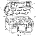
- FIGS. 17 and 18 illustrate another embodiment of a system 1010 for stacking and securing multiple storage containers 1014 (e.g., toolboxes, etc.) relative to one another.
- Each of the toolboxes 1014 includes a base 1022 and a lid 1018 pivotally coupled to the base 1022 and securable in a closed position.
- the system 1010 further includes an interface 1028 for mating complementary surfaces of the storage containers 1014 relative to one another.
- the storage containers include a coupling assembly (e.g., rotatable latches 1026) to selectively attach the lid 1018 of one toolbox 1014 to the base 1022 of another adjacent toolboxes 1014 at the interface 1028.
- a coupling assembly e.g., rotatable latches 1026
- the mating interface 1028 includes a plurality of polygonal features (e.g., projections, raised areas, and/or the like) positioned on a lid 1018 of one toolbox 1014 that fit in a complementary manner with features (e.g., recesses, pockets, and/or the like) positioned on the base 1022 of an adjacent toolbox 1014.
- the polygonal features include octagonal-shaped projections protruding from an upper surface of the lid 1018, and the base 1022 also includes octagonal-shaped projections that fit between the projections on the lid 1018.
- the toolboxes 1014 may be placed or stacked on top of another such that the latches 1026 of both toolboxes 1014 align vertically. The latches 1026 may then be actuated to secure the toolboxes 1014 to one another.
- the toolbox storage system 1010 includes two similar toolboxes 1014. In other embodiments, any number of toolboxes 1014 having the complementary surfaces of the interface 1028 may be stacked on one another. In such embodiments, the latches 1026 may be used to attach the any number of toolboxes 1014 to adjacent toolboxes 1014 in the toolbox storage system 1010.
- FIGS. 19 and 20 illustrate a storage system 1210 according to another embodiment.
- the storage system 1210 includes at least two storage containers 1214 (e.g., toolboxes, etc.) stackable and securable to one another.
- Each of the toolboxes 1214 includes a base 1222 and a lid 1218 pivotally coupled to the base 1222.
- the system 1210 further includes an interface 1228 for mating complementary surfaces of the storage containers 1214 relative to one another.
- the interface 1228 may include flanges or tabs on one toolbox 1214 that interlock with feet, pockets, or the like, of another toolbox 1214.
- a shape of the flanges or tabs may be similar to the shape of the feet or pockets such that the interface 1228 allows for multiple toolboxes 1214 to be stacked and nested with one another.
- Each of the toolboxes 1214 further includes a coupling assembly 1234 for locking the base 1222 of one toolbox 1214 to the lid 1218 of an adjacent toolbox 1214 at the interface 1228.
- the coupling assembly 1234 includes an actuator 1238 extending from the base 1222 and a receiver 1242 extending into the lid 1218.
- the coupling assembly 1234 could include other components, such as an actuator and receiver having different configurations.
- the actuator 1238 is a push-button, but other types of actuators 1238 such as a knob, lever, pull-tab, rotatable tab, dial, and/or or the like could be implemented.
- one toolbox 1214 may be stacked and nested on an adjacent toolbox 1214 at the interface 1228.
- a user may move the actuator 1238 in the direction of arrow 1246 to lock the toolboxes 1214 together.
- the user may move the actuator 1238 in a direction opposite of arrow 1246 to remove the actuator 1238 from the receiver 1242.
- the user may separate the toolboxes 1214 from one another.
- FIGS. 21-23C illustrate a storage system 1310 according to another embodiment.
- the storage system 1310 includes at least two storage containers 1314 (e.g., toolboxes, etc.) stackable and securable to one another.
- Each of the toolboxes 1314 includes a lid 1318 and a base 1322 pivotally coupled to the lid 1318.
- the system 1310 further includes an interface 1328 for mating complementary surfaces of the storage containers 1314 relative to one another.
- the interface 1328 may include flanges or tabs on one toolbox 1314 that interlock with feet, pockets, or the like, of another toolbox 1314.
- a shape of the flanges or tabs is similar to the shape of the feet or pockets such that the interface 1328 allows for multiple toolboxes 1314 to be stacked and nested with one another.
- Each of the toolboxes 1314 includes a coupling assembly 1334 for locking the base 1322 of one toolbox 1314 to the lid 1318 of an adjacent toolbox 1314 at the interface 1328.
- the coupling assembly 1334 includes an actuator 1338, a latch 1342 formed on the base 1322, and a recess 1346 molded into the lid 1318.
- the latch 1342 may be formed on the lid 1318 while the recess 1346 may be molded into the base 1322.
- the actuator 1338 is at least partially situated within the base 1322 and is rotatable relative to the base 1322 and lid 1318.
- the latch 1342 may be coupled to the actuator 1338 or integrally formed thereon to rotate with the actuator 1338 such that the latch 1342 is selectively received within the recess 1346.
- a user may manipulate a portion of the actuator 1338 that extends out of the base 1322 to operate the latch 1342 between a locked position ( FIG. 23A ) and an unlocked position ( FIG. 23B ).
- the locked position the latch 1342 of one toolbox 1314 is received in the recess 1346 on another adjacent toolbox 1314 to lock the base 1322 and lid 1318 of adjacent toolboxes 1314 together.
- the unlocked position the latch 1342 of one toolbox 1314 is not received in the recess 1346 on another adjacent toolbox 1314 such that the adjacent toolboxes 1314 may be separated from one another.
- FIGS. 23A-23C illustrate the steps of removing adjacent toolboxes 1314 from one another.
- FIG. 23A illustrates the latch 1342 in the locked position, which prevents the toolboxes 1314 from separating from one another.
- FIG. 23B illustrates the latch 1342 in the unlocked position, which results from a user rotating the actuator 1338 in the direction of arrow 1350. Such movement unlocks the toolboxes 1314 from another and allows the toolboxes 1314 to separate.
- the actuator 1338 is shown as being associated with rotational movement, those having skill in the art will appreciated that an actuator having non-rotational movement (e.g., translational sliding movement) may also be provided and is also contemplated herein. Solely moving the actuator 1338 as illustrated in FIG. 23B allows separation of adjacent toolboxes 1314 without forcing separation of adjacent toolboxes 1314.
- FIG. 23C illustrates separation of the toolboxes 1314 from one another completely in the direction of arrow 1354.
- the steps shown in FIGS. 23A-23C may take place in any order, and do not need to be initiated or completed in numerical order.
- a user may initiate the step illustrated in FIG. 23B but does not need to remove the toolboxes 1314 from one another completely.
- the latch 1342 and/or actuator 1338 include a ramped part to bias the latch 1342 and/or actuator 1338 into the locked position such that a user does not need to independently manipulate the actuator 1338 to lock adjacent toolboxes 1314 to one another.
- a user would only be required to reverse the actions illustrated in FIG. 23C by pressing toolboxes 1314 together in a direction opposite the arrow 1354, thereby urging the latch 1342 to the locked position and locking the adjacent toolboxes 1314 together.
- FIGS. 24 and 25 illustrate a storage system according to another embodiment.
- the storage system includes at least two storage containers 1414 (e.g., toolboxes, etc.) stackable and securable to one another.
- Each of the toolboxes 1414 includes a base 1422 and a lid 1418 pivotally coupled to the base 1422 by a hinge 1424.
- the lid 1418 and base 1422 are selectively moved between an open position and a closed latched position.
- the system further includes an interface 1428 for mating complementary surfaces of the storage containers 1414 relative to one another.
- the lid 1418 of one toolbox 1414 includes at least one bar or beam 1426 configured to fit into at least one slot 1430 within the base 1422 of another toolbox 1414.
- the lid 1418 includes two beams 1426
- the base 1422 includes two slots 1430.
- toolboxes 1414 include a larger number of beams 1426 and slots 1430. The toolboxes 1414 are stackable on one another such that the beams 1426 are inserted into the slots 1430.
- Each of the toolboxes 1414 include a coupling assembly 1434 disposed at least partially within a slot 1430 for selectively coupling the toolboxes 1414 to one another at the interface 1428.
- the coupling assembly 1434 includes multiple latches 1438 for locking the beams 1426 within the slots 1430.
- the latches 1438 may be spring loaded such that the beams 1426 are press or snap fitted into the latches 1438. Once the beams 1426 are pressed into the latches 1438 within the slots 1430, the latches 1438 snap into a locked position to lock the toolboxes 1414 together.
- FIG. 25 illustrates an exemplary embodiment of the coupling assembly 1434.
- the coupling assembly 1434 includes the beams 1426 and latches 1438 that form a binding apparatus.
- the base 1422 further includes at least one release button 1442 to selectively open, unlock, or un-snap the latches 1438.
- the release button 1442 when the release button 1442 is pressed, the latches 1438 move into an unlocked position, and the toolboxes 1414 may be separated from one another.
- the toolbox storage system may also include a variety of toolboxes having different capacities and sizes while each toolbox in the variety of toolboxes maintains the interface 1428.
Landscapes
- Engineering & Computer Science (AREA)
- Mechanical Engineering (AREA)
- Stackable Containers (AREA)
Applications Claiming Priority (3)
| Application Number | Priority Date | Filing Date | Title |
|---|---|---|---|
| US202062963234P | 2020-01-20 | 2020-01-20 | |
| US202063030694P | 2020-05-27 | 2020-05-27 | |
| US202063070633P | 2020-08-26 | 2020-08-26 |
Publications (1)
| Publication Number | Publication Date |
|---|---|
| EP3854718A1 true EP3854718A1 (de) | 2021-07-28 |
Family
ID=74194605
Family Applications (1)
| Application Number | Title | Priority Date | Filing Date |
|---|---|---|---|
| EP21152606.6A Pending EP3854718A1 (de) | 2020-01-20 | 2021-01-20 | Stapelbares lagersystem |
Country Status (6)
| Country | Link |
|---|---|
| US (2) | US12195230B2 (de) |
| EP (1) | EP3854718A1 (de) |
| CN (1) | CN215362410U (de) |
| AU (1) | AU2021100366A4 (de) |
| CA (1) | CA3106255A1 (de) |
| MX (1) | MX2021000811A (de) |
Cited By (2)
| Publication number | Priority date | Publication date | Assignee | Title |
|---|---|---|---|---|
| EP4029657A1 (de) * | 2020-08-07 | 2022-07-20 | Techtronic Cordless GP | Modulares aufbewahrungssystem |
| EP3974118A3 (de) * | 2020-09-25 | 2022-10-26 | Techtronic Cordless GP | Werkzeuglagersystem |
Families Citing this family (41)
| Publication number | Priority date | Publication date | Assignee | Title |
|---|---|---|---|---|
| CN110893610A (zh) | 2016-05-02 | 2020-03-20 | 凯特尔塑料有限公司 | 实用组件和联接机构 |
| WO2019028041A1 (en) | 2017-07-31 | 2019-02-07 | Milwaukee Electric Tool Corporation | Storage device system |
| CN111615481B (zh) | 2017-12-20 | 2022-11-04 | 凯特尔塑料有限公司 | 台车及其机械制动系统 |
| CN111867785A (zh) | 2018-01-24 | 2020-10-30 | 米沃奇电动工具公司 | 工具储存装置 |
| IL257294A (en) | 2018-02-01 | 2018-03-29 | Milwaukee Electric Tool Corp | Coupleable crate |
| IL260225A (en) | 2018-06-24 | 2018-07-31 | Keter Plastic Ltd | pushcart |
| US11486427B2 (en) * | 2018-07-18 | 2022-11-01 | The Stanley Works Israel Ltd. | Stacking latch mechanism |
| US11642777B2 (en) * | 2018-07-18 | 2023-05-09 | The Stanley Works Israel Ltd. | Stacking latch mechanism |
| US11027411B2 (en) | 2018-10-24 | 2021-06-08 | Tti (Macao Commercial Offshore) Limited | Saw stand |
| IL265964A (en) | 2019-04-11 | 2019-07-31 | Milwaukee Electric Tool Corp | A matching system and adapter for it |
| USD1007861S1 (en) * | 2019-09-10 | 2023-12-19 | Halex/Scott Fetzer Company | Container |
| IL269564B2 (en) | 2019-09-23 | 2023-11-01 | Keter Home & Garden Products Ltd | Sawhorse |
| CN215362410U (zh) * | 2020-01-20 | 2021-12-31 | 创科无线普通合伙 | 可堆叠存储系统,配合接口以及存储容器 |
| IL274945A (en) * | 2020-05-26 | 2021-12-01 | Keter Plastic Ltd | A set of containers and connectivity for them |
| US11890744B2 (en) | 2020-07-31 | 2024-02-06 | Techtronic Cordless Gp | Workbench-hand truck assembly |
| US11845178B2 (en) | 2020-11-03 | 2023-12-19 | Techtronic Cordless Gp | Modular work station |
| CN117677318A (zh) * | 2021-07-09 | 2024-03-08 | Gt线路有限公司 | 可运输容器的套组 |
| EP4122649A1 (de) * | 2021-07-21 | 2023-01-25 | Suzhou Dake Investment Consulation Co., Ltd. | Behälteranordnung und behälter |
| US11827415B2 (en) | 2021-09-16 | 2023-11-28 | Techtronic Cordless Gp | Storage box light |
| US12179956B2 (en) * | 2021-10-15 | 2024-12-31 | Makita U.S.A., Inc. | Modular storage system with storage box connectivity and external box features and accessories |
| US12312126B2 (en) * | 2021-11-03 | 2025-05-27 | Meridian International Co., Ltd | Stacked toolbox system |
| CN116142600A (zh) * | 2021-11-19 | 2023-05-23 | 国网江苏省电力有限公司营销服务中心 | 一种电力设备检测用可灵活堆叠的标准仪器机箱 |
| IT202100029675A1 (it) * | 2021-11-24 | 2023-05-24 | Mirco Verrando | Contenitore isolante per la pizza da asporto |
| US12161207B2 (en) * | 2022-01-26 | 2024-12-10 | Grown-Up Licenses Limited | Stack and lock system for storage product and storage container |
| US12532962B1 (en) | 2022-02-17 | 2026-01-27 | John Stokes | Modular cabinet for use with mobile storage receptacles |
| US20230278191A1 (en) * | 2022-03-04 | 2023-09-07 | Meridian International Co., Ltd | Connection structure of module, storage box and storage box assembly |
| EP4516689A4 (de) * | 2022-05-31 | 2025-08-13 | Hangzhou Great Star Ind Co Ltd | Verriegelungsvorrichtung und kombinierter behälter |
| EP4302929B1 (de) * | 2022-07-04 | 2025-04-02 | Stanley Black & Decker MEA FZE | Behälter mit riegel mit niedrigem profil |
| CN115158872A (zh) * | 2022-07-27 | 2022-10-11 | 重庆工业职业技术学院 | 一种景区应急物品存放管理装置及方法 |
| IL319447A (en) | 2022-09-14 | 2025-05-01 | Keter Home & Garden Products Ltd | Connectivity system for devices |
| USD1059829S1 (en) | 2022-10-14 | 2025-02-04 | Makita U.S.A., Inc. | Storage box |
| CN118025629A (zh) * | 2022-11-03 | 2024-05-14 | M·H·帕诺蒂安 | 具有附接槽的可堆叠存储容器 |
| DE102023106646B3 (de) * | 2023-03-16 | 2024-02-22 | Sortimo International Gmbh | Behälter zur lösbaren Anbringung an einer Haltevorrichtung |
| CN116408762B (zh) * | 2023-03-31 | 2025-09-26 | 宁波明良智能家居科技有限公司 | 一种堆叠工具箱 |
| US20250153899A1 (en) * | 2023-11-09 | 2025-05-15 | Doskocil Manufacturing Company, Inc. | Stackable container assembly |
| USD1109528S1 (en) | 2023-11-22 | 2026-01-20 | Aob Products Company | Hard case |
| US12583648B2 (en) | 2024-01-17 | 2026-03-24 | Black & Decker Inc. | Portable fluid tank system with mounting assembly |
| US12565885B2 (en) | 2024-01-17 | 2026-03-03 | Black & Decker Inc. | Portable fluid tank system with multi-state control interface and remote operation |
| US20250361068A1 (en) * | 2024-05-21 | 2025-11-27 | Milwaukee Electric Tool Corporation | Storage Devices for Modular Unit |
| US12528178B1 (en) * | 2024-07-18 | 2026-01-20 | Chang-yu Tsai | Tool box assembly |
| CN119388198A (zh) * | 2025-01-06 | 2025-02-07 | 易达精密机床(平湖)有限公司 | 一种数控机床用双层外置换刀装置 |
Citations (5)
| Publication number | Priority date | Publication date | Assignee | Title |
|---|---|---|---|---|
| US20050224494A1 (en) * | 2004-04-09 | 2005-10-13 | Mark Anthony Heinrichs | Container, and related methods |
| WO2016142935A1 (en) * | 2015-03-06 | 2016-09-15 | Keter Plastic Ltd. | Container assemblies |
| DE102015013053A1 (de) * | 2015-10-08 | 2017-04-13 | Plaston Ag | Stapelbarer Koffer mit Verbindungsvorrichtung |
| US20170166352A1 (en) * | 2015-12-14 | 2017-06-15 | Milwaukee Electric Tool Corporation | Storage device system |
| US20180161975A1 (en) * | 2016-05-02 | 2018-06-14 | Keter Plastic Ltd. | Utility assembly and coupling mechanism |
Family Cites Families (131)
| Publication number | Priority date | Publication date | Assignee | Title |
|---|---|---|---|---|
| US2541828A (en) | 1945-08-02 | 1951-02-13 | Mallory & Co Inc P R | Condenser mounting clip |
| GB692638A (en) | 1950-11-18 | 1953-06-10 | Clifford Gordon Davies | Group of boxes |
| US2695105A (en) | 1951-03-06 | 1954-11-23 | John P Mitchell | Shoe holding bracket |
| US3504405A (en) | 1968-03-04 | 1970-04-07 | Cecily Elliott Smith | Ski retaining device |
| DE2619702C2 (de) | 1976-05-04 | 1984-07-26 | Hilti Ag, Schaan | Schelle zur Aufnahme von Rohren, Kabeln und dgl. |
| US4351448A (en) * | 1980-08-08 | 1982-09-28 | General Electric Company | Packaging container for mining and construction tools |
| US4428487A (en) * | 1982-04-15 | 1984-01-31 | James Hepp | Dual side wall locking attachment for trays to vertical legs in sectional display rack |
| DE3407043A1 (de) * | 1984-02-27 | 1985-09-05 | Gregor Hofbauer GmbH, 8033 Planegg | Verpackungsbehaelter |
| DE4201264A1 (de) | 1992-01-18 | 1993-07-22 | Festo Kg | Stapelbarer koffer |
| US5359752A (en) | 1992-08-12 | 1994-11-01 | Georg Domenig | Laterally adjustable mounting bracket for use on a drawer and with a tongueless drawer guide in connection with a desk or cabinet |
| CH689863A5 (de) | 1993-05-27 | 1999-12-31 | Alfred Heer | Vorrichtung zum hängenden Anordnen eines längsausgedehnten Gegenstandes. |
| US5503277A (en) | 1993-08-09 | 1996-04-02 | Side-Kik Corporation | Display hook and combination |
| US5469961A (en) * | 1994-08-15 | 1995-11-28 | Chang; Chun Y. | Combined minidisc box |
| US5799915A (en) | 1995-01-31 | 1998-09-01 | The Burton Corporation | Twist rack for snowboards |
| US5669515A (en) | 1995-08-11 | 1997-09-23 | Suncast Corporation | Tool hanger |
| DE19718833C1 (de) | 1997-05-05 | 1998-09-24 | Konstanze Saathoff Fa | Halterung für kraftbetätigte Schrauber u. dgl. |
| IL128303A (en) | 1998-02-02 | 2002-02-10 | 500 Group Inc | Rolling containers assembly |
| US6347847B1 (en) | 1998-02-02 | 2002-02-19 | 500 Group Inc. | Rolling containers assembly |
| US6499608B1 (en) | 2000-02-14 | 2002-12-31 | John Sterling Corporation | Wall-mounted storage system |
| US6273259B1 (en) * | 2000-05-09 | 2001-08-14 | Norseman Plastics Limited | Container |
| DE50015397D1 (de) * | 2000-08-03 | 2008-11-20 | Aeg Electric Tools Gmbh | Werkzeugkoffer |
| US20020053529A1 (en) * | 2000-11-03 | 2002-05-09 | White Thomas M. | File storage container |
| US6415924B1 (en) | 2001-10-10 | 2002-07-09 | Stanely Chiro International Ltd. | Tool box with lateral sides for holding marked plates |
| US6874634B2 (en) * | 2003-01-29 | 2005-04-05 | Riley Medical, Inc. | Variably stackable sterilization tray system |
| DE20314301U1 (de) | 2003-09-17 | 2004-02-26 | Berner Gmbh | Stapelbarer Werkzeugkoffer |
| US7246718B2 (en) * | 2003-10-02 | 2007-07-24 | Zag Industries Ltd. | Toolbox with handle having cover locking mechanism |
| US20050247653A1 (en) | 2004-05-06 | 2005-11-10 | Dr. Brooks Innovations, L.L.C. | System for holding implements |
| CA2470272C (en) | 2004-06-08 | 2009-12-22 | Rudy Pfeiffer | Apparatus for storing a recreational board |
| TWI246954B (en) | 2004-10-26 | 2006-01-11 | Global Ind Holdings Ltd | Tool box hanging base |
| US20080121547A1 (en) | 2005-02-18 | 2008-05-29 | Hansjorg Dur | Connection System For Stackable Containers |
| US7721900B2 (en) | 2005-12-06 | 2010-05-25 | Waterman James R | Sportboard storage rack system |
| US20080054142A1 (en) | 2006-04-21 | 2008-03-06 | Deland Martin L | Display system |
| US9145230B2 (en) * | 2006-04-22 | 2015-09-29 | Tanos Gmbh Verpacken Ordnen Prasentieren | Storage device comprising two parts |
| US7845653B2 (en) | 2006-05-26 | 2010-12-07 | Zag Industries Ltd. | Transportable containers |
| DE202006008894U1 (de) | 2006-06-02 | 2006-08-03 | Jelenia Plast Sp. Z.O.O. | Behälter, insbesondere stapelbar, mit Spannverschluss |
| US20080000853A1 (en) | 2006-06-13 | 2008-01-03 | Jung Li Huang | Holder for implements |
| ITMI20061349A1 (it) * | 2006-07-12 | 2008-01-13 | Marco Alessandro Piacenza | Sistema di contenitori indipendenti impilabili |
| WO2008090546A1 (en) | 2007-01-22 | 2008-07-31 | Keter Plastic Ltd. | Rolling tool cart |
| US7661528B2 (en) * | 2007-11-30 | 2010-02-16 | Pwp Industries | Stackable twist-top container system |
| US20090145866A1 (en) | 2007-12-10 | 2009-06-11 | Michael Harmik Panosian | Wall organizing system |
| EP2346741B1 (de) * | 2008-05-19 | 2015-04-08 | TTS Tooltechnic Systems AG & Co. KG | Aus zwei teilen, wie zum beispiel zwei kästen oder einem kasten und einem deckel, bestehende lagerungsanordnung |
| US7832584B2 (en) | 2008-11-05 | 2010-11-16 | Custom-Pak, Inc. | Blow molded tool chest with sliding connector components |
| GB2467016B (en) | 2009-01-20 | 2013-07-10 | Kevin Brown | Container interlocking system |
| US8714355B2 (en) | 2009-03-04 | 2014-05-06 | Stanley Black & Decker, Inc. | Integrated storage system with locking containers |
| JP2010260625A (ja) | 2009-05-11 | 2010-11-18 | Makita Corp | 箱体及びその段積み構造 |
| US8132819B2 (en) | 2009-05-15 | 2012-03-13 | The Stanley Works Israel Ltd. | Rolling container assembly with mount structure |
| US8875888B2 (en) * | 2009-06-29 | 2014-11-04 | Tts Tooltechnic Systems Ag & Co. Kg | Stackable container assembly with reciprocal locking of the stacked containers |
| WO2011000387A1 (de) | 2009-06-29 | 2011-01-06 | Tts Tooltechnic Systems Ag & Co. Kg | Stapelbehäl teranordnung mit gegenseitiger verriegelung gestapelter behälter |
| CA2714163C (en) | 2009-09-01 | 2018-08-28 | The Stanley Works Israel Ltd. | Rolling container assembly with adjustable storage units |
| US9132543B2 (en) | 2009-09-01 | 2015-09-15 | The Stanley Works Israel Ltd. | Rolling container assembly with adjustable storage units |
| US8567796B2 (en) | 2009-09-01 | 2013-10-29 | The Stanley Works Israel Ltd. | Rolling container assembly with adjustable storage units |
| US8915382B2 (en) | 2009-09-15 | 2014-12-23 | Peter Totman | Apparatus and system for supporting a ski |
| US20110139777A1 (en) * | 2009-12-11 | 2011-06-16 | The Stanley Works Israel Ltd. | Container |
| USRE47022E1 (en) | 2009-12-11 | 2018-09-04 | The Stanley Works Israel Ltd. | Container |
| US8602217B2 (en) | 2009-12-11 | 2013-12-10 | The Stanley Works Israel Ltd. | Container |
| USD627967S1 (en) * | 2009-12-21 | 2010-11-30 | Tts Tooltechnic Systems Ag & Co. Kg | Storage box |
| US10022856B2 (en) | 2010-01-28 | 2018-07-17 | The Stanley Works Israel Ltd. | Metal and plastic container |
| US20110234072A1 (en) | 2010-03-23 | 2011-09-29 | Hightower Robert C | Bracket Assembly for Undermounted Drawer and Tray Slides in Cabinetry |
| US8308116B2 (en) | 2010-07-16 | 2012-11-13 | Liberty Hardware Mfg. Corp. | Hanger assembly |
| USD639059S1 (en) | 2010-08-12 | 2011-06-07 | The Stanley Works Israel Ltd. | Organizer |
| US9469024B2 (en) * | 2010-10-04 | 2016-10-18 | The Stanley Works Israel Ltd. | Container assembly |
| US8191845B1 (en) | 2011-01-10 | 2012-06-05 | Clair Home Products Inc. | Multi-function hook |
| US20130047386A1 (en) | 2011-02-17 | 2013-02-28 | Magpul Industries Corp. | Modular Stowage System |
| US8657307B2 (en) | 2011-06-22 | 2014-02-25 | The Stanley Works Israel Ltd. | Modular rolling container assembly |
| EP2596920B1 (de) | 2011-11-22 | 2018-06-06 | The Stanley Works Israel Ltd. | Modulare Behälteranordnung |
| CN202624826U (zh) | 2012-03-27 | 2012-12-26 | 花学林 | 组合战备器材箱 |
| US9206827B2 (en) | 2012-11-20 | 2015-12-08 | Avery Dennison Corporation | Wall mount organization system |
| US10047546B2 (en) | 2013-02-14 | 2018-08-14 | Keter Plastic Ltd. | Cabinet of storage units |
| US20140263119A1 (en) | 2013-03-12 | 2014-09-18 | Wilson Sporting Goods Co. | Racquet display system |
| US8967438B2 (en) | 2013-03-15 | 2015-03-03 | Suncast Technologies, Llc | Job box |
| EP2796248A1 (de) | 2013-04-25 | 2014-10-29 | The Stanley Works Israel Ltd. | Werkzeugkastendeckel |
| DE102013008630A1 (de) | 2013-05-22 | 2014-11-27 | Festool Gmbh | Tragbarer Behälter, insbesondere für eine Hand-Werkzeugmaschine |
| EP2994274B1 (de) | 2013-07-05 | 2017-05-31 | TTS Tooltechnic Systems AG & Co. KG | Behälteranordnung |
| CN203427004U (zh) | 2013-08-27 | 2014-02-12 | 瑞塑精密模具(嘉兴)有限公司 | 组合式工具箱 |
| US9193060B2 (en) * | 2013-12-04 | 2015-11-24 | Tefenplast Ltd. | Tool box assembly |
| US9393684B2 (en) * | 2014-04-01 | 2016-07-19 | Meridian International Co., Ltd. | Toolbox |
| DK3166758T3 (en) | 2014-07-12 | 2019-04-15 | Festool Gmbh | Stacking device and transport container with bus interfaces |
| DE102014010378A1 (de) | 2014-07-12 | 2016-01-14 | Festool Gmbh | Transportbehälter mit einem Behältereinsatz |
| US10575417B2 (en) | 2014-09-08 | 2020-02-25 | The Stanley Works Israel Ltd. | Jobsite communications center |
| CN107073702A (zh) | 2014-09-08 | 2017-08-18 | 史丹利工具(以色列)有限公司 | 工作现场通信中心 |
| US9962825B2 (en) | 2014-09-12 | 2018-05-08 | Stanley Black & Decker, Inc. | Multifunctional toolbox |
| DE202014008993U1 (de) | 2014-11-14 | 2015-01-13 | A-Tina Tools Co., Ltd. | Werkzeugkoffer mit einer Stapelfunktion |
| US9393685B2 (en) | 2014-11-24 | 2016-07-19 | A-Tina Tools Co., Ltd. | Toolbox with a stacking function |
| DE202014105771U1 (de) * | 2014-11-28 | 2015-01-13 | Tahsin Dag | Verpackungsbehälter |
| US9802741B2 (en) * | 2014-12-10 | 2017-10-31 | Becklin Holdings, Inc. | Container with padlock mount |
| DE102014118452A1 (de) * | 2014-12-11 | 2016-06-16 | Adolf Würth GmbH & Co. KG | Koffer |
| WO2017016573A1 (de) | 2015-07-24 | 2017-02-02 | Tts Tooltechnic Systems Ag & Co. Kg | Aufbewahrungseinrichtung |
| AU2015101015B4 (en) | 2015-07-29 | 2018-09-27 | Hilu, Marcelo | Bracket |
| JP6580421B2 (ja) | 2015-08-25 | 2019-09-25 | 株式会社トプコン | キャリングケース |
| US9701443B2 (en) | 2015-11-02 | 2017-07-11 | Compass Corporation | Set of stackable tool boxes |
| US10138032B2 (en) | 2015-11-09 | 2018-11-27 | Chi-Hsiung Chang | Fastener assembly |
| WO2017098511A1 (en) | 2015-12-10 | 2017-06-15 | Keter Plastic Ltd. | Wheeled container handle assembly |
| MX2018006801A (es) * | 2015-12-10 | 2018-08-09 | Keter Plastic Ltd | Ensamble de contenedor. |
| EP3189944B1 (de) | 2016-01-07 | 2018-06-27 | Festool GmbH | Stapelbehälter mit einer übertragungseinrichtung |
| WO2017135830A1 (en) | 2016-02-01 | 2017-08-10 | Manchester Securities Limited | Amusement ride |
| US9962827B2 (en) | 2016-03-24 | 2018-05-08 | Jui-Chien Kao | Hand tool frame |
| USD795579S1 (en) | 2016-03-30 | 2017-08-29 | The Stanley Works Israel Ltd | Organizer |
| DE102016112854A1 (de) | 2016-07-13 | 2018-01-18 | Bs Systems Gmbh & Co. Kg | Stapelbarer Systembehälter |
| US9725209B1 (en) | 2016-09-14 | 2017-08-08 | Tefenplast Ltd. | Stackable tool box assembly |
| DE102016218116A1 (de) | 2016-09-21 | 2018-03-22 | Robert Bosch Gmbh | Verriegelungsbauteil zum Verriegeln aufeinander gestapelter Koffer und Werkzeugkoffer mit einem solchen Verriegelungsbauteil |
| WO2018213560A1 (en) | 2017-05-17 | 2018-11-22 | Milwaukee Electric Tool Corporation | Storage device system |
| WO2019028041A1 (en) * | 2017-07-31 | 2019-02-07 | Milwaukee Electric Tool Corporation | Storage device system |
| USD896517S1 (en) | 2017-08-09 | 2020-09-22 | Keter Plastic Ltd. | Tool box |
| CN207480547U (zh) | 2017-10-24 | 2018-06-12 | 国家电网公司 | 一种便于携带的多功能电力电网工具箱 |
| US10603783B2 (en) | 2017-12-04 | 2020-03-31 | Black & Decker Inc. | Tool container system |
| CN111615481B (zh) | 2017-12-20 | 2022-11-04 | 凯特尔塑料有限公司 | 台车及其机械制动系统 |
| CN111867785A (zh) | 2018-01-24 | 2020-10-30 | 米沃奇电动工具公司 | 工具储存装置 |
| IL257294A (en) | 2018-02-01 | 2018-03-29 | Milwaukee Electric Tool Corp | Coupleable crate |
| US10894314B2 (en) | 2018-02-14 | 2021-01-19 | Stanley Black & Decker Inc. | Container attachment system |
| US11006749B2 (en) | 2018-03-23 | 2021-05-18 | Hni Technologies Inc. | Systems, brackets, and methods for mounting storage structures to office work surfaces |
| CN208514468U (zh) | 2018-05-08 | 2019-02-19 | 国家电网公司 | 移动便携组合式电力试验化验工具箱 |
| CN208428223U (zh) | 2018-05-08 | 2019-01-25 | 国家电网公司 | 移动式多功能电力电气试验工具箱 |
| CN208470372U (zh) | 2018-07-12 | 2019-02-05 | 国网山东省电力公司东营供电公司 | 一种可自由组合的抢修周转箱 |
| CN208887986U (zh) | 2018-08-13 | 2019-05-21 | 国网浙江省电力有限公司绍兴供电公司 | 手推抽屉式组合取样箱 |
| CA3110268A1 (en) * | 2018-09-14 | 2020-03-19 | Tanos Gmbh Verpacken Ordnen Prasentieren | Storage device |
| US11643252B2 (en) * | 2018-09-14 | 2023-05-09 | Tanos Gmbh | Storage device |
| USD880155S1 (en) | 2018-09-21 | 2020-04-07 | Enping YiFeng Plastic & Mould Co., Ltd. | Toolbox |
| CN209289229U (zh) | 2019-01-09 | 2019-08-23 | 湖南工程职业技术学院 | 一种计算机实训室用电脑主机组装装置 |
| CN209774596U (zh) | 2019-01-10 | 2019-12-13 | 中国南方电网有限责任公司超高压输电公司检修试验中心 | 一种组合式电力检修工具箱 |
| EP3911917A4 (de) * | 2019-01-18 | 2022-10-05 | PCP Ammunition Company, LLC | Ineinandergreifende stapelbare munitionsbehälter |
| CN113518694B (zh) * | 2019-03-06 | 2024-06-18 | 米沃奇电动工具公司 | 具有发光部件的储存单元 |
| IL265964A (en) | 2019-04-11 | 2019-07-31 | Milwaukee Electric Tool Corp | A matching system and adapter for it |
| USD923935S1 (en) * | 2019-05-31 | 2021-07-06 | Keter Plastic Ltd. | Toolbox |
| AT522666B1 (de) * | 2019-06-06 | 2022-01-15 | Holzleithner Andreas | Transportbehälter |
| CN211483271U (zh) * | 2019-11-27 | 2020-09-15 | 上海美瑞实业有限公司 | 箱体互锁结构 |
| CN215362410U (zh) * | 2020-01-20 | 2021-12-31 | 创科无线普通合伙 | 可堆叠存储系统,配合接口以及存储容器 |
| EP4135934A4 (de) * | 2020-04-14 | 2024-06-19 | Milwaukee Electric Tool Corporation | Aufbewahrungsvorrichtung mit multifunktionsdeckel |
| CN111924270B (zh) * | 2020-07-29 | 2022-05-20 | 上海美瑞实业有限公司 | 自动互锁结构、储物箱、储物箱组件 |
| EP4323154A4 (de) | 2021-04-13 | 2025-03-26 | Milwaukee Electric Tool Corporation | Kopplungsplattform für ein versorgungsmodul |
| USD970847S1 (en) | 2022-05-10 | 2022-11-22 | Sheng Chen | Lock box |
| EP4302929B1 (de) * | 2022-07-04 | 2025-04-02 | Stanley Black & Decker MEA FZE | Behälter mit riegel mit niedrigem profil |
-
2021
- 2021-01-20 CN CN202120157971.2U patent/CN215362410U/zh active Active
- 2021-01-20 AU AU2021100366A patent/AU2021100366A4/en active Active
- 2021-01-20 MX MX2021000811A patent/MX2021000811A/es unknown
- 2021-01-20 EP EP21152606.6A patent/EP3854718A1/de active Pending
- 2021-01-20 CA CA3106255A patent/CA3106255A1/en active Pending
- 2021-01-20 US US17/153,251 patent/US12195230B2/en active Active
-
2024
- 2024-12-10 US US18/975,098 patent/US20250100748A1/en active Pending
Patent Citations (5)
| Publication number | Priority date | Publication date | Assignee | Title |
|---|---|---|---|---|
| US20050224494A1 (en) * | 2004-04-09 | 2005-10-13 | Mark Anthony Heinrichs | Container, and related methods |
| WO2016142935A1 (en) * | 2015-03-06 | 2016-09-15 | Keter Plastic Ltd. | Container assemblies |
| DE102015013053A1 (de) * | 2015-10-08 | 2017-04-13 | Plaston Ag | Stapelbarer Koffer mit Verbindungsvorrichtung |
| US20170166352A1 (en) * | 2015-12-14 | 2017-06-15 | Milwaukee Electric Tool Corporation | Storage device system |
| US20180161975A1 (en) * | 2016-05-02 | 2018-06-14 | Keter Plastic Ltd. | Utility assembly and coupling mechanism |
Cited By (3)
| Publication number | Priority date | Publication date | Assignee | Title |
|---|---|---|---|---|
| EP4029657A1 (de) * | 2020-08-07 | 2022-07-20 | Techtronic Cordless GP | Modulares aufbewahrungssystem |
| EP3974118A3 (de) * | 2020-09-25 | 2022-10-26 | Techtronic Cordless GP | Werkzeuglagersystem |
| EP4234175A3 (de) * | 2020-09-25 | 2023-11-08 | Techtronic Cordless GP | Werkzeuglagersystem |
Also Published As
| Publication number | Publication date |
|---|---|
| US20210221561A1 (en) | 2021-07-22 |
| AU2021100366A4 (en) | 2021-04-15 |
| CA3106255A1 (en) | 2021-07-20 |
| US20250100748A1 (en) | 2025-03-27 |
| MX2021000811A (es) | 2021-07-21 |
| CN215362410U (zh) | 2021-12-31 |
| US12195230B2 (en) | 2025-01-14 |
Similar Documents
| Publication | Publication Date | Title |
|---|---|---|
| AU2021100366A4 (en) | Stackable storage system | |
| CN215968664U (zh) | 工具储存系统 | |
| US20250296735A1 (en) | Tool Storage | |
| EP0221749B1 (de) | Lagerungsbehälter für Aufnahmeträger | |
| US5575401A (en) | Portable storage assembly | |
| EP0081933B1 (de) | Behälter für Bandkassette | |
| EP2347966B1 (de) | Stapelbarer Behälter | |
| CA2694801C (en) | Integrated storage system with locking containers | |
| US9469024B2 (en) | Container assembly | |
| EP2474393B1 (de) | Behälter mit einem Riegel | |
| EP2338650B1 (de) | Elektrowerkzeug-Aufbewahrungskasten | |
| EP2465649A2 (de) | Abdichtbarer Aufbewahrungsbehälter | |
| JPH0451429B2 (de) | ||
| US5634732A (en) | Binding assembly for binders | |
| CN215825289U (zh) | 工具盒 | |
| CN223836059U (zh) | 堆叠系统 | |
| JP2001114319A (ja) | 開閉容器におけるロック構造 | |
| US20250136323A1 (en) | Dual connector | |
| CN214924259U (zh) | 工具盒 | |
| JP2642275B2 (ja) | 中皿付き裁縫箱 | |
| WO2025158289A1 (en) | Dual connector | |
| CN222134933U (zh) | 模块化工具容器 | |
| JP3693419B2 (ja) | 折畳みコンテナにおける底板固定構造 | |
| CN121552449A (zh) | 一种美工刀 | |
| JP2025186887A (ja) | クロージャ |
Legal Events
| Date | Code | Title | Description |
|---|---|---|---|
| PUAI | Public reference made under article 153(3) epc to a published international application that has entered the european phase |
Free format text: ORIGINAL CODE: 0009012 |
|
| STAA | Information on the status of an ep patent application or granted ep patent |
Free format text: STATUS: THE APPLICATION HAS BEEN PUBLISHED |
|
| AK | Designated contracting states |
Kind code of ref document: A1 Designated state(s): AL AT BE BG CH CY CZ DE DK EE ES FI FR GB GR HR HU IE IS IT LI LT LU LV MC MK MT NL NO PL PT RO RS SE SI SK SM TR |
|
| STAA | Information on the status of an ep patent application or granted ep patent |
Free format text: STATUS: REQUEST FOR EXAMINATION WAS MADE |
|
| 17P | Request for examination filed |
Effective date: 20211015 |
|
| RBV | Designated contracting states (corrected) |
Designated state(s): AL AT BE BG CH CY CZ DE DK EE ES FI FR GB GR HR HU IE IS IT LI LT LU LV MC MK MT NL NO PL PT RO RS SE SI SK SM TR |
|
| STAA | Information on the status of an ep patent application or granted ep patent |
Free format text: STATUS: EXAMINATION IS IN PROGRESS |
|
| 17Q | First examination report despatched |
Effective date: 20230406 |