EP3854736B1 - Distributeur de ruban de protection - Google Patents
Distributeur de ruban de protection Download PDFInfo
- Publication number
- EP3854736B1 EP3854736B1 EP20153200.9A EP20153200A EP3854736B1 EP 3854736 B1 EP3854736 B1 EP 3854736B1 EP 20153200 A EP20153200 A EP 20153200A EP 3854736 B1 EP3854736 B1 EP 3854736B1
- Authority
- EP
- European Patent Office
- Prior art keywords
- guide
- protective tape
- base
- linking
- blade holder
- Prior art date
- Legal status (The legal status is an assumption and is not a legal conclusion. Google has not performed a legal analysis and makes no representation as to the accuracy of the status listed.)
- Active
Links
Images



Classifications
-
- B—PERFORMING OPERATIONS; TRANSPORTING
- B65—CONVEYING; PACKING; STORING; HANDLING THIN OR FILAMENTARY MATERIAL
- B65H—HANDLING THIN OR FILAMENTARY MATERIAL, e.g. SHEETS, WEBS, CABLES
- B65H35/00—Delivering articles from cutting or line-perforating machines; Article or web delivery apparatus incorporating cutting or line-perforating devices, e.g. adhesive tape dispensers
- B65H35/0006—Article or web delivery apparatus incorporating cutting or line-perforating devices
- B65H35/002—Hand-held or table apparatus
- B65H35/0026—Hand-held or table apparatus for delivering pressure-sensitive adhesive tape
- B65H35/0033—Hand-held or table apparatus for delivering pressure-sensitive adhesive tape and affixing it to a surface
-
- B—PERFORMING OPERATIONS; TRANSPORTING
- B65—CONVEYING; PACKING; STORING; HANDLING THIN OR FILAMENTARY MATERIAL
- B65H—HANDLING THIN OR FILAMENTARY MATERIAL, e.g. SHEETS, WEBS, CABLES
- B65H35/00—Delivering articles from cutting or line-perforating machines; Article or web delivery apparatus incorporating cutting or line-perforating devices, e.g. adhesive tape dispensers
- B65H35/0006—Article or web delivery apparatus incorporating cutting or line-perforating devices
- B65H35/0073—Details
- B65H35/008—Arrangements or adaptations of cutting devices
- B65H35/0086—Arrangements or adaptations of cutting devices using movable cutting elements
-
- B—PERFORMING OPERATIONS; TRANSPORTING
- B65—CONVEYING; PACKING; STORING; HANDLING THIN OR FILAMENTARY MATERIAL
- B65H—HANDLING THIN OR FILAMENTARY MATERIAL, e.g. SHEETS, WEBS, CABLES
- B65H2301/00—Handling processes for sheets or webs
- B65H2301/50—Auxiliary process performed during handling process
- B65H2301/51—Modifying a characteristic of handled material
- B65H2301/515—Cutting handled material
- B65H2301/5153—Details of cutting means
- B65H2301/51532—Blade cutter, e.g. single blade cutter
-
- B—PERFORMING OPERATIONS; TRANSPORTING
- B65—CONVEYING; PACKING; STORING; HANDLING THIN OR FILAMENTARY MATERIAL
- B65H—HANDLING THIN OR FILAMENTARY MATERIAL, e.g. SHEETS, WEBS, CABLES
- B65H2402/00—Constructional details of the handling apparatus
- B65H2402/30—Supports; Subassemblies; Mountings thereof
-
- B—PERFORMING OPERATIONS; TRANSPORTING
- B65—CONVEYING; PACKING; STORING; HANDLING THIN OR FILAMENTARY MATERIAL
- B65H—HANDLING THIN OR FILAMENTARY MATERIAL, e.g. SHEETS, WEBS, CABLES
- B65H2402/00—Constructional details of the handling apparatus
- B65H2402/30—Supports; Subassemblies; Mountings thereof
- B65H2402/31—Pivoting support means
-
- B—PERFORMING OPERATIONS; TRANSPORTING
- B65—CONVEYING; PACKING; STORING; HANDLING THIN OR FILAMENTARY MATERIAL
- B65H—HANDLING THIN OR FILAMENTARY MATERIAL, e.g. SHEETS, WEBS, CABLES
- B65H2402/00—Constructional details of the handling apparatus
- B65H2402/30—Supports; Subassemblies; Mountings thereof
- B65H2402/32—Sliding support means
Definitions
- the present invention relates to a tape dispenser, and more particularly to a protective tape dispenser.
- a conventional tape applicator includes a handle, a blade holder and a tape roll seat above the handle.
- the blade holder is disposed in front of the tape roll seat.
- a roller is provided below the blade holder.
- a blade is insertedly connected to the blade holder.
- a protective tape roll is sleeved onto the tape roll seat.
- one end of the protective tape of the protective tape roll is attached to a product to be sealed.
- the protective tape is pulled to stretch an appropriate length.
- the protective tape of the protective tape roll is attached to the surface of the product.
- the protective tape is cut by the blade, so that the packing process can be effectively simplified and the operation efficiency can be improved.
- the above-mentioned tape dispenser is easy to operate for use.
- the protective tape is used for protecting an article and keeping the article from being damaged during carrying and transportation. Therefore, the protective tape needs a large force to be cut when in use.
- the protective tape cannot be aligned with the edge of the article when applying the protective tape, resulting in incomplete protection and being unsightly. Accordingly, the inventor of the present invention has devoted himself based on his many years of practical experiences to solve these problems.
- US 2019/0352121 A1 discloses a tape applicator comprising a frame, a source of tape, a front applicator assembly to apply a leading end of a tape from said source to a leading face of a carton, a rear wipe down assembly to wipe a tape applied to said carton, a push bar link interconnecting said applicator assembly and said wipe down assembly for movement together to form a tape applicator assembly, a cut-off mechanism mounted on said frame, a nonlinear helical coil applicator spring and a nonlinear helical coil cut-off spring, a spring pressure adjuster mechanism including an actuator and a controller controlling the delivery of power to said actuator to have low tension in said applicator spring and said cut-off spring and to increase tensions in the applicator and said cut-off springs before said wipe down and cut-off mechanism are activated.
- GB 2 367 282 A discloses a carton-sealing tape cutter comprising a first shell body, a second shell body, a tape sleeve ring, a grip handle, and a blade cutter having a structure comprising: a tape sleeve ring installed on a tape-setting space of the first shell body and of the second shell body, a hinge installed between the tape-setting space and the cutter-setting space of the second shell body, a tape-guiding board installed in the bottom part of the tape-setting space, and a blade-connecting board installed on said cutter-setting space, enabling the lower end of the gripping device to attach the surface of tape tightly while cutting.
- the primary object of the present invention is to provide a protective tape dispenser, which can quickly attach the protective tape to the edge of a product, has the advantages of complete protection and increased aesthetics, and can increase the smoothness of operation, so as to achieve the purpose of labor-saving operation and easy force application.
- the protective tape dispenser of the present invention comprises a base, a mounting unit, a handle, a guide unit, a cutting unit, a tape pressing unit.
- the base has an abutting portion at a bottom thereof.
- the base has a pivot member.
- the mounting unit is pivotally connected to the base.
- the mounting unit is configured to mount a protective tape roll.
- the handle is disposed on the base.
- the guide unit is disposed on the base.
- the guide unit includes a tape pressing member and a turning member.
- the tape pressing member is located between the mounting unit and the turning member.
- the cutting unit is disposed on the base.
- the cutting unit includes an operation member and a fixing seat. The operation member is pivotally connected to the pivot member.
- the operation member has a linking portion and a pressing portion that are located at two sides of the pivot member.
- a free end of the linking portion is connected to one end of an elastic member.
- Another end of the elastic member is fixed to the base.
- the fixing seat is fixed to the base.
- the fixing seat has a positioning member.
- the positioning member is connected with a blade holder.
- the blade holder is movable along the positioning member.
- the blade holder is provided with a blade.
- the tape pressing unit is pivotally connected to the abutting portion.
- the tape pressing unit has a first guide member and a second guide member.
- the protective tape dispenser provided by the present invention
- the protective tape of the protective tape roll is pulled out to pass around the outer side of the turning member along the inner side of the tape pressing member, and is pulled to the outer sides of the first guide member and the second guide member.
- the technical feature that the turning member extends out of the base can increase the tension of the protective tape and facilitate cutting.
- the operation member drives the linking member to actuate the blade holder so as to extend or retract the blade, thereby increasing the smoothness of operation.
- the guide plate is use to guide the base to quickly align with the edge of a product.
- the present invention has the advantages of complete protection and increased aesthetics, thereby achieving the purposes of labor-saving operation and easy force application.
- FIG. 1 is a perspective view in accordance with a preferred embodiment of the present invention.
- FIG. 2 is another perspective view in accordance with the preferred embodiment of the present invention.
- FIG. 3 is a side view of a first side plate in accordance with the preferred embodiment of the present invention.
- the present invention discloses a protective tape dispenser 100.
- the protective tape dispenser 100 comprises a base 10, a mounting unit 20, a handle 30, a guide unit 40, a cutting unit 50, and a tape pressing unit 60.
- the base 10 has a first side plate 11 and an opposing second side plate 12.
- the first side plate 11 and the second side plate 12 are generally a plate.
- the first side plate 11 and the second side plate 12 each include a middle portion 111, an abutting portion 112 at the bottom of the middle portion 111, and an extension portion 113 extending obliquely from the top of the middle portion 111.
- the shape of the extension portion 113 of the first side plate 11 is different from the shape of the extension portion of the second side plate 12.
- An angle ⁇ is defined between a side edge 114 of the middle portion 111 and a bottom edge 115 of the abutting portion 112. The angle ⁇ is less than 90 degrees.
- a guide plate 13 is connected to one side of the abutting portion 112 of the first side plate 11.
- a guide portion 14 extends outward from one side edge and a bottom edge of the guide plate 13.
- the guide portion 14 extends out of the first side plate 11.
- the guide portion 14 has a guide block 15.
- the thickness of the guide block 15 is greater than the thickness of the guide portion 14.
- the guide block 15 is located between the first side plate 11 and the second side plate 12.
- the guide block 15 is configured to guide the base 10 to be used aside, so as to align with a product.
- the mounting unit 20 is pivotally connected to the extension portion 113 of the first side plate 11.
- the mounting unit 20 is configured to mount a protective tape roll 21.
- the handle 30, referring to FIG. 4 is disposed between the extension portion 113 of the first side plate 11 and the extension portion of the second side plate 12, and is located under the mounting unit 20.
- the handle 30 has a holding portion 31 and a mounting portion 32.
- the mounting portion 32 is fixedly connected to the extension portion 113 of the first side plate 11.
- a pivot member 33 is inserted through the front end of the mounting portion 32.
- the pivot member 33 is a pivot shaft.
- the pivot member 33 is fixedly connected to the extension portion 113 of the first side plate 11 and the extension portion of the second side plate 12.
- the guide unit 40 includes a tape pressing member 41 and a turning member 42.
- the tape pressing member 41 is rotatably, pivotally disposed on the extension portion 113 of the first side plate 11, and is located under the mounting unit 20.
- the tape pressing member 41 is sleeved with a stop ring 411.
- the stop ring 411 is movable and adjustable on the tape pressing member 41 according to the width of the protective tape roll 21.
- the turning member 42 is fixedly disposed between the middle portion 111 of the first side plate 11 and the middle portion of the second side plate 12, and is located under the tape pressing member 41.
- the turning member 42 is not cylindrical and cannot be rotated.
- the turning member 42 has a turning surface 43.
- the turning surface 43 extends out of the base 10. In this embodiment of the present invention, the turning surface 43 is a curved surface.
- FIG. 5 and FIG. 6 are cross-sectional views in accordance with the preferred embodiment of the present invention.
- the cutting unit 50 includes an operation member 51 and a fixing seat 52.
- the operation member 51 is pivotally connected to the pivot member 33.
- the operation member 51 has a linking portion 511 and a pressing portion 512 that are located at two sides of the pivot member 33. In this embodiment of the present invention, the length of the linking portion 511 is less than the length of the pressing portion 512.
- the linking portion 511 is pivotally connected with a linking member 53.
- the linking member 53 is pivotally connected with a linking plate 54.
- the linking plate 54 has a plurality of perforations 541. A free end of the linking portion 511 is provided with a pair of elastic members 55.
- the other ends of the elastic members 55 are fixed to a fixed shaft 16 provided on the middle portion 111 of the first side plate 11.
- the elastic members 55 are springs.
- the fixing seat 52 is fixedly disposed between the first side plate 11 and the second side plate 12.
- the fixing seat 52 has a fixing surface 521.
- the fixing surface 521 is perpendicular to the linking plate 54 and can abut against the linking plate 54.
- the fixing surface 521 is provided with a through hole 522.
- a positioning member 56 is fixed to the through hole 522.
- the positioning member 56 is a shaft.
- the positioning member 56 is parallel to the linking plate 54.
- the positioning member 56 is connected with a blade holder 57.
- the fixing seat 52 and the blade holder 57 are spaced from each other.
- the blade holder 57 is provided with a transverse shaft hole 571.
- the positioning member 56 is inserted in the shaft hole 571, so that the blade holder 57 can move along the positioning member 56.
- the blade holder 57 is provided with a plurality of longitudinal fixing holes 572.
- a blade 58 is provided on the top of the blade holder 57.
- the blade 58 has a cutting edge 581 and a plurality of grooves 582.
- a plurality of fixing members 59 are inserted through the grooves 582, the perforations 541 and the fixing holes 572 for fixing the blade 58 to the blade holder 57, so that the blade 58, the linking plate 54 and the blade holder 57 can move along the positioning member 56.
- the tape pressing unit 60 is pivotally connected to the abutting portion 112 of the first side plate 11 and the abutting portion of the second side plate 12.
- the tape pressing unit 60 has a first guide member 61 and a second guide member 62.
- the first guide member 61 is positioned at the turning point of the angle ⁇ and is located under the blade holder 57, so that the blade holder 57 is located between the turning member 42 and the first guide member 61.
- the second guide member 62 is located under the handle 30.
- the guide block 15 is located at the outer edges of the first guide member 61 and the second guide member 62.
- the first guide member 61 and the second guide member 62 are rollers.
- the inner diameter of the first guide member 61 is greater than the inner diameter of the second guide member 62.
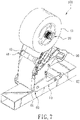
- FIG. 7 and FIG. 8 are schematic views in accordance with the preferred embodiment of the present invention when in use.
- the protective tape roll 21 is first mounted on the mounting unit 20, and then the protective tape of the protective tape roll 21 is pulled out to pass around the outer side of the turning member 42 along the inner side of the pressing member 41.
- the inner side is defined as facing the inside of the base 10
- the outer side is defined as facing the outside of the base 10.
- the protective tape is pulled to the outer sides of the first guide member 61 and the second guide member 62.
- the user holds the protective tape dispenser 100 and applies the protective tape to attach to a product.
- the protective tape of the protective tape roll 21 is pulled out smoothly and attached to the product.
- the user can move the stop ring 411 sleeved on the tape pressing member 41 to an appropriate position according to the width of the protective tape of the protective tape roll 21, so that the protective tape is confined between the first side plate 11 and the stop ring 411 to prevent the protective tape from deflecting in the process of adhering to the product.
- the bottom edge of the first side plate 11 is connected to the guide plate 13.
- the guide plate 13 can guide the base 10 to align with the product quickly.
- the user When the user wants to use the blade 58 to cut the protective tape, the user only needs to press the pressing portion 512 of the operation member 51 to pivot the linking portion 511 of the operation member 51 about the pivot member 33.
- the linking member 53 is pivoted to drive the linking plate 54, so that the linking plate 54 can push the blade holder 57 and the blade 58 simultaneously, and the cutting edge 581 of the blade 58 extends out of the base 10. Because the turning member 42 extends out of the base 10, the protective tape passing through the tape pressing member 41 will change its angle, thereby turning and increasing the tension of the protective tape. In addition to increasing the flatness of the protective tape attached to the product, the cutting edge 581 of the blade 58 can cut the protective tape easily.
- the remaining protective tape of the protective tape roll 21 stays on the turning member 42 to facilitate the user to pull the protective tape next time.
- the elastic force of the elastic members 55 will pull back the linking portion 511 of the operation member 51 and simultaneously retract the linking member 53, the blade holder 57 and the blade 58 without interfering with the operation of the protective tape dispenser 100.
- the length of the linking portion 511 is less than the length of the pressing portion 512.
- the angle ⁇ is defined between the side edge 114 of the middle portion 111 and the bottom edge 115 of the abutting portion 112 to maintain the uprightness of the protective tape dispenser 100 when in use.
- the blade 58 is kept a distance from the product without contacting the product, so as to maintain the appearance of the product.
Landscapes
- Adhesive Tape Dispensing Devices (AREA)
Claims (10)
- Distributeur de ruban de protection (100), comprenant :une base (10), présentant une partie d'appui (112) au niveau d'un fond de celle-ci, la base (10) présentant un élément de pivotement (33) ;une unité de montage (20), reliée de manière pivotante à la base (10), l'unité de montage (20) étant configurée pour supporter un rouleau de ruban de protection (21) ;une poignée (30), disposée sur la base (10) ;une unité de guidage (40), disposée sur la base (10), l'unité de guidage (40) incluant un élément de pression de ruban (41) et un élément de renvoi (42), l'élément de pression de ruban (41) étant situé entre l'unité de montage (20) et l'élément de renvoi (42) ;une unité de coupe (50), disposée sur la base (10), l'unité de coupe (50) incluant un élément d'actionnement (51) et un siège de fixation (52), l'élément d'actionnement (51) étant relié de manière pivotante à l'élément de pivotement (33), l'élément d'actionnement (51) présentant une partie de liaison (511) et une partie de pression (512) qui sont situées sur deux côtés de l'élément de pivotement (33), une extrémité libre de la partie de liaison (511) étant reliée à une extrémité d'un élément élastique (55), une autre extrémité de l'élément élastique (55) étant fixée à la base (10), le siège de fixation (52) étant fixé à la base (10), le siège de fixation (52) présentant un élément de positionnement (56), l'élément de positionnement (56) étant relié à un porte-lame (57), le porte-lame (57) étant mobile le long de l'élément de positionnement (56), le porte-lame (57) étant pourvu d'une lame (58) ;une unité de pression de ruban (60), reliée de manière pivotante à la partie d'appui (112), l'unité de pression de ruban (60) présentant un premier élément de guidage (61) et un second élément de guidage (62).
- Distributeur de ruban de protection selon la revendication 1, dans lequel la partie de liaison (511) est reliée de manière pivotante à un élément de liaison (53), l'élément de liaison (53) est relié de manière pivotante à une plaque de liaison (54), le siège de fixation (52) présente une surface de fixation (521), la surface de fixation (521) est perpendiculaire à la plaque de liaison (54) et vient en appui contre la plaque de liaison (54), l'élément de positionnement (56) est fixé à la surface de fixation (521), l'élément de positionnement (56) est parallèle à la plaque de liaison (54), le siège de fixation (52) et le porte-lame (57) sont espacés l'un de l'autre et le porte-lame (57) est situé entre l'élément de renvoi (42) et le premier élément de guidage (61).
- Distributeur de ruban de protection selon la revendication 2, dans lequel la plaque de liaison (54) présente une pluralité de perforations (541), le porte-lame (57) est pourvu d'une pluralité de trous de fixation (572), la lame (58) présente une pluralité de rainures (582) et une pluralité d'éléments de fixation (59) sont insérés à travers les rainures (582), les perforations (541) et les trous de fixation (572) pour fixer la lame (58) au porte-lame (57).
- Distributeur de ruban de protection selon la revendication 1, dans lequel le porte-lame (57) est muni d'un trou d'axe (571) et l'élément de positionnement (56) est disposé par insertion dans le trou d'axe (571).
- Distributeur de ruban de protection selon la revendication 1, dans lequel la partie de liaison (511) a une longueur inférieure à celle de la partie de pression (512).
- Distributeur de ruban de protection selon la revendication 1, dans lequel la base (10) présente une première plaque latérale (11) et une seconde plaque latérale (12), une plaque de guidage (13) est reliée à un fond de la première plaque latérale (11), une partie de guidage (14) s'étend vers l'extérieur depuis la plaque de guidage (13), la partie de guidage (14) présente un bloc de guidage (15) et le bloc de guidage (15) est situé au niveau de bords extérieurs du premier élément de guidage (61) et du second élément de guidage (62).
- Distributeur de ruban de protection selon la revendication 1, dans lequel la base (10) présente un bord latéral (114) et un bord inférieur (115), un angle (θ) est défini entre le bord latéral (114) et le bord inférieur (115), et l'angle (θ) est inférieur à 90 degrés.
- Distributeur de ruban de protection selon la revendication 1, dans lequel le premier élément de guidage (61) et le second élément de guidage (62) sont des rouleaux et le premier élément de guidage (61) a un diamètre intérieur supérieur à celui du second élément de guidage (62).
- Distributeur de ruban de protection selon la revendication 1, dans lequel une bague d'arrêt (411) est emmanchée sur l'élément de pression de ruban (41).
- Distributeur de ruban de protection selon la revendication 1, dans lequel l'élément de pression de ruban (41) est situé entre l'unité de montage (20) et l'élément de renvoi (42), l'élément de renvoi (42) n'est pas rotatif, l'élément de renvoi (42) présente une surface de renvoi (43) et la surface de renvoi (43) s'étend à l'extérieur de la base (10).
Priority Applications (1)
| Application Number | Priority Date | Filing Date | Title |
|---|---|---|---|
| EP20153200.9A EP3854736B1 (fr) | 2020-01-22 | 2020-01-22 | Distributeur de ruban de protection |
Applications Claiming Priority (1)
| Application Number | Priority Date | Filing Date | Title |
|---|---|---|---|
| EP20153200.9A EP3854736B1 (fr) | 2020-01-22 | 2020-01-22 | Distributeur de ruban de protection |
Publications (2)
| Publication Number | Publication Date |
|---|---|
| EP3854736A1 EP3854736A1 (fr) | 2021-07-28 |
| EP3854736B1 true EP3854736B1 (fr) | 2022-05-11 |
Family
ID=69187705
Family Applications (1)
| Application Number | Title | Priority Date | Filing Date |
|---|---|---|---|
| EP20153200.9A Active EP3854736B1 (fr) | 2020-01-22 | 2020-01-22 | Distributeur de ruban de protection |
Country Status (1)
| Country | Link |
|---|---|
| EP (1) | EP3854736B1 (fr) |
Cited By (1)
| Publication number | Priority date | Publication date | Assignee | Title |
|---|---|---|---|---|
| WO2026131021A1 (fr) * | 2024-12-16 | 2026-06-25 | Wolfcraft Gmbh | Dispositif pour fixer une bande sur la surface d'un composant |
Families Citing this family (1)
| Publication number | Priority date | Publication date | Assignee | Title |
|---|---|---|---|---|
| TWI883409B (zh) * | 2023-03-22 | 2025-05-11 | 元貝實業股份有限公司 | 具有導引功能之膠帶施用器 |
Family Cites Families (4)
| Publication number | Priority date | Publication date | Assignee | Title |
|---|---|---|---|---|
| US6540002B1 (en) * | 1999-07-15 | 2003-04-01 | Equity Earnings Corp. | Apparatus for dispensing mesh drywall tape |
| GB2367282A (en) * | 2000-10-02 | 2002-04-03 | Lin Shih Chin | Tape dispenser with cutter and tape gripping device |
| KR100533838B1 (ko) * | 2004-04-30 | 2005-12-07 | 이상철 | 접착테이프용 디스펜서 |
| US20190352121A1 (en) * | 2018-05-16 | 2019-11-21 | Lamus Enterprises Inc. | Tape applicator pressure control |
-
2020
- 2020-01-22 EP EP20153200.9A patent/EP3854736B1/fr active Active
Cited By (1)
| Publication number | Priority date | Publication date | Assignee | Title |
|---|---|---|---|---|
| WO2026131021A1 (fr) * | 2024-12-16 | 2026-06-25 | Wolfcraft Gmbh | Dispositif pour fixer une bande sur la surface d'un composant |
Also Published As
| Publication number | Publication date |
|---|---|
| EP3854736A1 (fr) | 2021-07-28 |
Similar Documents
| Publication | Publication Date | Title |
|---|---|---|
| US5456422A (en) | Tape applying device | |
| US4379019A (en) | Masking machine | |
| US8955572B2 (en) | Trigger-operated adhesive tape displenser | |
| US5921450A (en) | Tape dispenser | |
| US8839838B2 (en) | Adhesive tape dispenser | |
| US10791885B1 (en) | Paper towel dispenser | |
| US4667891A (en) | Masking machine | |
| US20090183837A1 (en) | Tape dispenser that dispenses overlapping tape and paper structures | |
| US10815093B1 (en) | Protective tape dispenser | |
| US4783016A (en) | Roll holder with retention member | |
| WO2011080977A1 (fr) | Dispositif de distribution de ruban adhésif et applicateur de ruban adhésif | |
| US20040099380A1 (en) | Double-sided adhesive tape dispenser | |
| KR101809835B1 (ko) | 테이프 디스펜서 및 테이프 접이방법 | |
| EP3854736A1 (fr) | Distributeur de ruban de protection | |
| US3787271A (en) | Tape and apron dispensing apparatus | |
| CA2389466A1 (fr) | Applicateur de ruban adhesif | |
| JP6887383B2 (ja) | 手動テープアプリケータ装置 | |
| US7819162B2 (en) | Masking machines | |
| AU2020100111A4 (en) | Protective tape dispenser | |
| US5683542A (en) | Roll holder with retention member | |
| US6170726B1 (en) | Dispenser roller providing extended material end | |
| GB1580379A (en) | Hand labeller | |
| CN216376878U (zh) | 保护胶带施用器 | |
| US6478067B1 (en) | Adhesive tape dispenser provided with cutter for cutting tape, and the like of a package to facilitate the unpacking of the package | |
| FR2802845A1 (fr) | Unite de faconnage et massicotage a couteaux circulaires et guillotine |
Legal Events
| Date | Code | Title | Description |
|---|---|---|---|
| PUAI | Public reference made under article 153(3) epc to a published international application that has entered the european phase |
Free format text: ORIGINAL CODE: 0009012 |
|
| STAA | Information on the status of an ep patent application or granted ep patent |
Free format text: STATUS: REQUEST FOR EXAMINATION WAS MADE |
|
| 17P | Request for examination filed |
Effective date: 20200929 |
|
| AK | Designated contracting states |
Kind code of ref document: A1 Designated state(s): AL AT BE BG CH CY CZ DE DK EE ES FI FR GB GR HR HU IE IS IT LI LT LU LV MC MK MT NL NO PL PT RO RS SE SI SK SM TR |
|
| GRAP | Despatch of communication of intention to grant a patent |
Free format text: ORIGINAL CODE: EPIDOSNIGR1 |
|
| STAA | Information on the status of an ep patent application or granted ep patent |
Free format text: STATUS: GRANT OF PATENT IS INTENDED |
|
| GRAJ | Information related to disapproval of communication of intention to grant by the applicant or resumption of examination proceedings by the epo deleted |
Free format text: ORIGINAL CODE: EPIDOSDIGR1 |
|
| GRAP | Despatch of communication of intention to grant a patent |
Free format text: ORIGINAL CODE: EPIDOSNIGR1 |
|
| INTG | Intention to grant announced |
Effective date: 20211011 |
|
| INTG | Intention to grant announced |
Effective date: 20211026 |
|
| GRAS | Grant fee paid |
Free format text: ORIGINAL CODE: EPIDOSNIGR3 |
|
| GRAA | (expected) grant |
Free format text: ORIGINAL CODE: 0009210 |
|
| STAA | Information on the status of an ep patent application or granted ep patent |
Free format text: STATUS: THE PATENT HAS BEEN GRANTED |
|
| AK | Designated contracting states |
Kind code of ref document: B1 Designated state(s): AL AT BE BG CH CY CZ DE DK EE ES FI FR GB GR HR HU IE IS IT LI LT LU LV MC MK MT NL NO PL PT RO RS SE SI SK SM TR |
|
| REG | Reference to a national code |
Ref country code: GB Ref legal event code: FG4D |
|
| REG | Reference to a national code |
Ref country code: CH Ref legal event code: EP |
|
| REG | Reference to a national code |
Ref country code: AT Ref legal event code: REF Ref document number: 1491272 Country of ref document: AT Kind code of ref document: T Effective date: 20220515 |
|
| REG | Reference to a national code |
Ref country code: DE Ref legal event code: R096 Ref document number: 602020003070 Country of ref document: DE |
|
| REG | Reference to a national code |
Ref country code: IE Ref legal event code: FG4D |
|
| REG | Reference to a national code |
Ref country code: NL Ref legal event code: FP |
|
| REG | Reference to a national code |
Ref country code: LT Ref legal event code: MG9D |
|
| REG | Reference to a national code |
Ref country code: AT Ref legal event code: MK05 Ref document number: 1491272 Country of ref document: AT Kind code of ref document: T Effective date: 20220511 |
|
| PG25 | Lapsed in a contracting state [announced via postgrant information from national office to epo] |
Ref country code: SE Free format text: LAPSE BECAUSE OF FAILURE TO SUBMIT A TRANSLATION OF THE DESCRIPTION OR TO PAY THE FEE WITHIN THE PRESCRIBED TIME-LIMIT Effective date: 20220511 Ref country code: PT Free format text: LAPSE BECAUSE OF FAILURE TO SUBMIT A TRANSLATION OF THE DESCRIPTION OR TO PAY THE FEE WITHIN THE PRESCRIBED TIME-LIMIT Effective date: 20220912 Ref country code: NO Free format text: LAPSE BECAUSE OF FAILURE TO SUBMIT A TRANSLATION OF THE DESCRIPTION OR TO PAY THE FEE WITHIN THE PRESCRIBED TIME-LIMIT Effective date: 20220811 Ref country code: LT Free format text: LAPSE BECAUSE OF FAILURE TO SUBMIT A TRANSLATION OF THE DESCRIPTION OR TO PAY THE FEE WITHIN THE PRESCRIBED TIME-LIMIT Effective date: 20220511 Ref country code: HR Free format text: LAPSE BECAUSE OF FAILURE TO SUBMIT A TRANSLATION OF THE DESCRIPTION OR TO PAY THE FEE WITHIN THE PRESCRIBED TIME-LIMIT Effective date: 20220511 Ref country code: GR Free format text: LAPSE BECAUSE OF FAILURE TO SUBMIT A TRANSLATION OF THE DESCRIPTION OR TO PAY THE FEE WITHIN THE PRESCRIBED TIME-LIMIT Effective date: 20220812 Ref country code: FI Free format text: LAPSE BECAUSE OF FAILURE TO SUBMIT A TRANSLATION OF THE DESCRIPTION OR TO PAY THE FEE WITHIN THE PRESCRIBED TIME-LIMIT Effective date: 20220511 Ref country code: BG Free format text: LAPSE BECAUSE OF FAILURE TO SUBMIT A TRANSLATION OF THE DESCRIPTION OR TO PAY THE FEE WITHIN THE PRESCRIBED TIME-LIMIT Effective date: 20220811 Ref country code: AT Free format text: LAPSE BECAUSE OF FAILURE TO SUBMIT A TRANSLATION OF THE DESCRIPTION OR TO PAY THE FEE WITHIN THE PRESCRIBED TIME-LIMIT Effective date: 20220511 |
|
| PG25 | Lapsed in a contracting state [announced via postgrant information from national office to epo] |
Ref country code: RS Free format text: LAPSE BECAUSE OF FAILURE TO SUBMIT A TRANSLATION OF THE DESCRIPTION OR TO PAY THE FEE WITHIN THE PRESCRIBED TIME-LIMIT Effective date: 20220511 Ref country code: PL Free format text: LAPSE BECAUSE OF FAILURE TO SUBMIT A TRANSLATION OF THE DESCRIPTION OR TO PAY THE FEE WITHIN THE PRESCRIBED TIME-LIMIT Effective date: 20220511 Ref country code: LV Free format text: LAPSE BECAUSE OF FAILURE TO SUBMIT A TRANSLATION OF THE DESCRIPTION OR TO PAY THE FEE WITHIN THE PRESCRIBED TIME-LIMIT Effective date: 20220511 Ref country code: IS Free format text: LAPSE BECAUSE OF FAILURE TO SUBMIT A TRANSLATION OF THE DESCRIPTION OR TO PAY THE FEE WITHIN THE PRESCRIBED TIME-LIMIT Effective date: 20220911 |
|
| PG25 | Lapsed in a contracting state [announced via postgrant information from national office to epo] |
Ref country code: SM Free format text: LAPSE BECAUSE OF FAILURE TO SUBMIT A TRANSLATION OF THE DESCRIPTION OR TO PAY THE FEE WITHIN THE PRESCRIBED TIME-LIMIT Effective date: 20220511 Ref country code: SK Free format text: LAPSE BECAUSE OF FAILURE TO SUBMIT A TRANSLATION OF THE DESCRIPTION OR TO PAY THE FEE WITHIN THE PRESCRIBED TIME-LIMIT Effective date: 20220511 Ref country code: RO Free format text: LAPSE BECAUSE OF FAILURE TO SUBMIT A TRANSLATION OF THE DESCRIPTION OR TO PAY THE FEE WITHIN THE PRESCRIBED TIME-LIMIT Effective date: 20220511 Ref country code: ES Free format text: LAPSE BECAUSE OF FAILURE TO SUBMIT A TRANSLATION OF THE DESCRIPTION OR TO PAY THE FEE WITHIN THE PRESCRIBED TIME-LIMIT Effective date: 20220511 Ref country code: EE Free format text: LAPSE BECAUSE OF FAILURE TO SUBMIT A TRANSLATION OF THE DESCRIPTION OR TO PAY THE FEE WITHIN THE PRESCRIBED TIME-LIMIT Effective date: 20220511 Ref country code: DK Free format text: LAPSE BECAUSE OF FAILURE TO SUBMIT A TRANSLATION OF THE DESCRIPTION OR TO PAY THE FEE WITHIN THE PRESCRIBED TIME-LIMIT Effective date: 20220511 Ref country code: CZ Free format text: LAPSE BECAUSE OF FAILURE TO SUBMIT A TRANSLATION OF THE DESCRIPTION OR TO PAY THE FEE WITHIN THE PRESCRIBED TIME-LIMIT Effective date: 20220511 |
|
| REG | Reference to a national code |
Ref country code: DE Ref legal event code: R097 Ref document number: 602020003070 Country of ref document: DE |
|
| PLBE | No opposition filed within time limit |
Free format text: ORIGINAL CODE: 0009261 |
|
| STAA | Information on the status of an ep patent application or granted ep patent |
Free format text: STATUS: NO OPPOSITION FILED WITHIN TIME LIMIT |
|
| PG25 | Lapsed in a contracting state [announced via postgrant information from national office to epo] |
Ref country code: AL Free format text: LAPSE BECAUSE OF FAILURE TO SUBMIT A TRANSLATION OF THE DESCRIPTION OR TO PAY THE FEE WITHIN THE PRESCRIBED TIME-LIMIT Effective date: 20220511 |
|
| 26N | No opposition filed |
Effective date: 20230214 |
|
| REG | Reference to a national code |
Ref country code: CH Ref legal event code: PL |
|
| PG25 | Lapsed in a contracting state [announced via postgrant information from national office to epo] |
Ref country code: LU Free format text: LAPSE BECAUSE OF NON-PAYMENT OF DUE FEES Effective date: 20230122 |
|
| PG25 | Lapsed in a contracting state [announced via postgrant information from national office to epo] |
Ref country code: LI Free format text: LAPSE BECAUSE OF NON-PAYMENT OF DUE FEES Effective date: 20230131 Ref country code: CH Free format text: LAPSE BECAUSE OF NON-PAYMENT OF DUE FEES Effective date: 20230131 |
|
| REG | Reference to a national code |
Ref country code: DE Ref legal event code: R082 Ref document number: 602020003070 Country of ref document: DE Representative=s name: KANDLBINDER, MARKUS, DIPL.-PHYS., DE |
|
| PG25 | Lapsed in a contracting state [announced via postgrant information from national office to epo] |
Ref country code: IT Free format text: LAPSE BECAUSE OF FAILURE TO SUBMIT A TRANSLATION OF THE DESCRIPTION OR TO PAY THE FEE WITHIN THE PRESCRIBED TIME-LIMIT Effective date: 20220511 Ref country code: IE Free format text: LAPSE BECAUSE OF NON-PAYMENT OF DUE FEES Effective date: 20230122 |
|
| PG25 | Lapsed in a contracting state [announced via postgrant information from national office to epo] |
Ref country code: MC Free format text: LAPSE BECAUSE OF FAILURE TO SUBMIT A TRANSLATION OF THE DESCRIPTION OR TO PAY THE FEE WITHIN THE PRESCRIBED TIME-LIMIT Effective date: 20220511 |
|
| PG25 | Lapsed in a contracting state [announced via postgrant information from national office to epo] |
Ref country code: MC Free format text: LAPSE BECAUSE OF FAILURE TO SUBMIT A TRANSLATION OF THE DESCRIPTION OR TO PAY THE FEE WITHIN THE PRESCRIBED TIME-LIMIT Effective date: 20220511 |
|
| PG25 | Lapsed in a contracting state [announced via postgrant information from national office to epo] |
Ref country code: BG Free format text: LAPSE BECAUSE OF FAILURE TO SUBMIT A TRANSLATION OF THE DESCRIPTION OR TO PAY THE FEE WITHIN THE PRESCRIBED TIME-LIMIT Effective date: 20220511 |
|
| PG25 | Lapsed in a contracting state [announced via postgrant information from national office to epo] |
Ref country code: BG Free format text: LAPSE BECAUSE OF FAILURE TO SUBMIT A TRANSLATION OF THE DESCRIPTION OR TO PAY THE FEE WITHIN THE PRESCRIBED TIME-LIMIT Effective date: 20220511 |
|
| PG25 | Lapsed in a contracting state [announced via postgrant information from national office to epo] |
Ref country code: CY Free format text: LAPSE BECAUSE OF FAILURE TO SUBMIT A TRANSLATION OF THE DESCRIPTION OR TO PAY THE FEE WITHIN THE PRESCRIBED TIME-LIMIT; INVALID AB INITIO Effective date: 20200122 |
|
| PG25 | Lapsed in a contracting state [announced via postgrant information from national office to epo] |
Ref country code: HU Free format text: LAPSE BECAUSE OF FAILURE TO SUBMIT A TRANSLATION OF THE DESCRIPTION OR TO PAY THE FEE WITHIN THE PRESCRIBED TIME-LIMIT; INVALID AB INITIO Effective date: 20200122 |
|
| PG25 | Lapsed in a contracting state [announced via postgrant information from national office to epo] |
Ref country code: TR Free format text: LAPSE BECAUSE OF FAILURE TO SUBMIT A TRANSLATION OF THE DESCRIPTION OR TO PAY THE FEE WITHIN THE PRESCRIBED TIME-LIMIT Effective date: 20220511 |
|
| PG25 | Lapsed in a contracting state [announced via postgrant information from national office to epo] |
Ref country code: SI Free format text: LAPSE BECAUSE OF FAILURE TO SUBMIT A TRANSLATION OF THE DESCRIPTION OR TO PAY THE FEE WITHIN THE PRESCRIBED TIME-LIMIT Effective date: 20220511 |
|
| PGFP | Annual fee paid to national office [announced via postgrant information from national office to epo] |
Ref country code: NL Payment date: 20260121 Year of fee payment: 7 |
|
| PGFP | Annual fee paid to national office [announced via postgrant information from national office to epo] |
Ref country code: GB Payment date: 20260122 Year of fee payment: 7 |
|
| PGFP | Annual fee paid to national office [announced via postgrant information from national office to epo] |
Ref country code: DE Payment date: 20260323 Year of fee payment: 7 |
|
| PGFP | Annual fee paid to national office [announced via postgrant information from national office to epo] |
Ref country code: BE Payment date: 20260121 Year of fee payment: 7 |
|
| PGFP | Annual fee paid to national office [announced via postgrant information from national office to epo] |
Ref country code: FR Payment date: 20260121 Year of fee payment: 7 |