EP3854746B1 - Système de levage et procédé de levage d'un objet suspendu verticalement - Google Patents
Système de levage et procédé de levage d'un objet suspendu verticalement Download PDFInfo
- Publication number
- EP3854746B1 EP3854746B1 EP20153151.4A EP20153151A EP3854746B1 EP 3854746 B1 EP3854746 B1 EP 3854746B1 EP 20153151 A EP20153151 A EP 20153151A EP 3854746 B1 EP3854746 B1 EP 3854746B1
- Authority
- EP
- European Patent Office
- Prior art keywords
- hoisting
- winch
- winch drum
- water
- hoisting rope
- Prior art date
- Legal status (The legal status is an assumption and is not a legal conclusion. Google has not performed a legal analysis and makes no representation as to the accuracy of the status listed.)
- Active
Links
Images


Classifications
-
- B—PERFORMING OPERATIONS; TRANSPORTING
- B63—SHIPS OR OTHER WATERBORNE VESSELS; RELATED EQUIPMENT
- B63B—SHIPS OR OTHER WATERBORNE VESSELS; EQUIPMENT FOR SHIPPING
- B63B21/00—Tying-up; Shifting, towing, or pushing equipment; Anchoring
- B63B21/20—Adaptations of chains, ropes, hawsers, or the like, or of parts thereof
-
- B—PERFORMING OPERATIONS; TRANSPORTING
- B65—CONVEYING; PACKING; STORING; HANDLING THIN OR FILAMENTARY MATERIAL
- B65G—TRANSPORT OR STORAGE DEVICES, e.g. CONVEYORS FOR LOADING OR TIPPING, SHOP CONVEYOR SYSTEMS OR PNEUMATIC TUBE CONVEYORS
- B65G67/00—Loading or unloading vehicles
- B65G67/60—Loading or unloading ships
-
- B—PERFORMING OPERATIONS; TRANSPORTING
- B66—HOISTING; LIFTING; HAULING
- B66C—CRANES; LOAD-ENGAGING ELEMENTS OR DEVICES FOR CRANES, CAPSTANS, WINCHES, OR TACKLES
- B66C23/00—Cranes comprising essentially a beam, boom, or triangular structure acting as a cantilever and mounted for translatory of swinging movements in vertical or horizontal planes or a combination of such movements, e.g. jib-cranes, derricks, tower cranes
- B66C23/18—Cranes comprising essentially a beam, boom, or triangular structure acting as a cantilever and mounted for translatory of swinging movements in vertical or horizontal planes or a combination of such movements, e.g. jib-cranes, derricks, tower cranes specially adapted for use in particular purposes
- B66C23/36—Cranes comprising essentially a beam, boom, or triangular structure acting as a cantilever and mounted for translatory of swinging movements in vertical or horizontal planes or a combination of such movements, e.g. jib-cranes, derricks, tower cranes specially adapted for use in particular purposes mounted on road or rail vehicles; Manually-movable jib-cranes for use in workshops; Floating cranes
- B66C23/52—Floating cranes
-
- B—PERFORMING OPERATIONS; TRANSPORTING
- B66—HOISTING; LIFTING; HAULING
- B66D—CAPSTANS; WINCHES; TACKLES, e.g. PULLEY BLOCKS; HOISTS
- B66D1/00—Rope, cable, or chain winding mechanisms; Capstans
- B66D1/28—Other constructional details
- B66D1/30—Rope, cable, or chain drums or barrels
-
- B—PERFORMING OPERATIONS; TRANSPORTING
- B66—HOISTING; LIFTING; HAULING
- B66D—CAPSTANS; WINCHES; TACKLES, e.g. PULLEY BLOCKS; HOISTS
- B66D1/00—Rope, cable, or chain winding mechanisms; Capstans
- B66D1/28—Other constructional details
- B66D1/40—Control devices
- B66D1/48—Control devices automatic
- B66D1/52—Control devices automatic for varying rope or cable tension, e.g. when recovering craft from water
-
- B—PERFORMING OPERATIONS; TRANSPORTING
- B66—HOISTING; LIFTING; HAULING
- B66C—CRANES; LOAD-ENGAGING ELEMENTS OR DEVICES FOR CRANES, CAPSTANS, WINCHES, OR TACKLES
- B66C13/00—Other constructional features or details
- B66C13/02—Devices for facilitating retrieval of floating objects, e.g. for recovering crafts from water
Definitions
- the invention relates to a hoisting system for hoisting a vertically-suspended object, the hoisting system having a winch having a winch drum with a hoisting rope.
- the invention further relates to a method for hoisting a vertically-suspended object with such hoisting system.
- Hoisting systems for hoisting vertically-suspended objects are known from the prior art. Examples of such hoisting systems are cranes, A-frames with winches mounted on them and overboard sheaves combined with winches. Such hoisting systems may typically be placed on vessels, platforms, semis and jack-up rigs. In addition, these hoisting systems may be placed at or over a moon pool or they operate directly over the sea via further sheaves that are guiding a hoisting rope from a winch to the operation point.
- An example hoisting system may be a crane, which typically comprises a crane pedestal, a main boom pivotable connected to the crane pedestal, a knuckle-boom (or jib) pivotable connected to the main boom.
- Such crane further comprises a winch having a winch drum with a hoisting rope.
- the hoisting rope is typically guided from the winch along the main boom and knuckle-boom to the boom tip at the end of the knuckle-boom. Wire sheaves are generally placed along this path to guide the hoisting rope.
- the known hoisting systems function well, but their winches may become very bulky (and thereby costly) due to the required length and thickness of the hoisting rope, which is to be designed for the minimum breakable load required by the application. This is particularly so for offshore hoisting systems, wherein lengths of the hoisting rope may be up to several kilometres in order to be able to reach the seabed.
- US3,809,334A discloses a cable winch for helicopter installation which comprises a guide sheave assembly utilizing a trunnion and carriage assembly for the guide pulley including a reaction bar and rollers to transmit the horizontal component of cable tension into the reaction bar.
- the installation further comprises a reaction strut for supporting the guide sheave assembly and which is pivoted to follow traversing motion of the guide sheave assembly.
- the installation comprises a levelwind mechanism having a two-speed drive for traversing of the guide sheave assembly and automatic means for changing traversing speed during cable deploy or retrieval.
- the installation comprises a load cell in the guide sheave assembly support for measuring cable tension.
- the invention has for its object to remedy or to reduce at least one of the drawbacks of the prior art, or at least provide a useful alternative to prior art.
- the invention in a first aspect relates to a hoisting system for hoisting a vertically-suspended object, the hoisting system having a winch having a winch drum with a hoisting rope.
- a first part of the hoisting rope has a first diameter and a second part has a second diameter being larger than the first diameter, the first part being connected with a first end of the second part.
- the first part is an inner part on the winch drum when the winch drum is completely wound.
- the second part has a further end that is connectable to the object for hoisting the object, wherein a ratio between the first diameter and the second diameter is chosen such that the minimum breakable load of the first part differs less than a factor of four from the minimum breakable load of the second part, and preferably less than a factor of three.
- the first important feature of the invention is that the hoisting rope on the winch comprises at least two parts having different diameter, wherein the inner part of the winch (that is unwound the latest) comprises the thinner part of the hoisting robe. Furthermore, the diameters are chosen such that the minimum breakable load between said parts does not differ more than a factor of four, and preferably less than a factor of three.
- the inventors have realized that this combination of features leads to an enormous advantage in offshore hoisting applications. When a heavy and bulky load is hoisted offshore, either lifted from the seabed or placed onto the seabed the buoyancy forces acting by the water on the object cause the load on the hoisting rope to be significantly smaller.
- the inventors have seen a 66-ton-weighing object (in air) resulting in a 20-ton load on the hoisting rope (and hoisting system) when the object is fully submerged underwater. This is a factor of 3,3 difference, even though in most applications the weight reduction will be between 20% and 50%, resulting in ratio of the minimum breakable load (of the first and second part) between about 1,2 and 2.
- the inventors came to the realization that this opens up the possibility to exploit this effect. Instead of designing the complete hoisting rope for the 66-ton load capacity the major part of the hoisting rope may be designed for a much smaller load. In practical applications the second part does not need to be longer than 200 metres or 300 metres.
- the remainder which may easily have lengths up to several thousands of meters may be designed with a significantly smaller diameter. Consequently, the winch may be designed much smaller and additionally a lot of material (and costs) are saved for the hoisting rope material.
- the latter effect is in fact quite large as hoisting rope is very costly, particularly fibre ropes. Nevertheless, for metal ropes the impact is also quite large.
- the invention is therefore not limited to any specific type of hoisting rope.
- rope is used, this is to be interpreted as similar to the words cable and wire.
- the length of the second part of the hoisting rope is chosen such that, while, in operational use, the object is suspended in the hoisting rope and touches the water, the second part remains wound around the winch drum with at least a predefined number of windings and stretches all the way from the winch drum along the hoisting system and down to the further end of the hoisting rope near the water.
- the advantage of this embodiment is that it creates a safety zone during the hoisting where an effective minimum breakable strength of the hoisting rope is maintained higher in the transition from air-suspended to submerged load.
- the second part to be used as hoisting rope it needs to be wound around the winch at least a predefined number of times in order to create enough friction on the winch. In practical applications this may be 5 times or more, for example.
- the first part and the second part are connected through a tapered transition region.
- the second part has a length between 10 and 500 metres, and preferably between 10 and 400 metres, and even more preferably between 10 and 300 metres. This embodiment gives the range for the length of the second part, which is suitable for most applications.
- the first part has a length between 10 and 10000 metres, and preferably between 20 and 5000 metres, and even more preferably between 30 and 3000 metres. This embodiment gives the range for the length of the first part, which is suitable for most applications.
- the first diameter of the first part of the hoisting rope is between 5mm and 300mm . This embodiment gives the range for the diameter of the first part, which is suitable for most applications.
- the second diameter of the second part of the hoisting rope is between 25mm and 500mm . This embodiment gives the range for the diameter of the suitable part, which is suitable for most applications.
- the invention in a second aspect relates to a method for hoisting a vertically-suspended object with a hoisting system in accordance with the first aspect of the invention.
- the method comprises a step of hoisting the object either into or from the water, in such a way that the second part of the winch drum is always at least partially wound on the winch drum before the object is lifted out of the water during lifting of the object, and that the first part is not unwound from the winch drum before the object is fully submerged in the water during lowering of the object.
- the step of lowering the object at least a predefined number of windings of the second part remain on the winch drum until the object is exactly fully submerged.
- the advantage of this embodiment is that it creates a safety zone during the hoisting where an effective minimum breakable strength of the hoisting rope is maintained higher in the transition from air-suspended to submerged load.
- the second part to be used as hoisting rope it needs to be wound around the winch at least a predefined number of times in order to create enough friction on the winch. In practical applications this may be 5 times or more, for example.
- the step of lifting the object at least a predefined number of windings of the second part are wound on the winch drum before the object is no longer fully submerged.
- the advantage of this embodiment is that it creates a safety zone during the hoisting where an effective minimum breakable strength of the hoisting rope is maintained higher in the transition from air-suspended to submerged load.
- the second part to be used as hoisting rope it needs to be wound around the winch at least a predefined number of times in order to create enough friction on the winch. In practical applications this may be 5 times or more, for example.
- One benefit of the invention is the reduced rope weight, but the main advantage is the reduced overall cost and size of the hoisting system (i.e. crane).
- the hoisting rope determines a major part of the total cost, and by reducing the hoisting rope diameter the winch may be downsized as the rope diameter is a design factor for determining the required dimension of the winch drum and rope sheaves. These reductions also affect the overall cost and size of the total hoisting system.
- the invention may be used in connection with hoisting systems (i.e. cranes, A-frames with winches mounted on them, and overboard sheaves combined with winches), where fibre ropes are used for load handling offshore, but the invention also applies to steel ropes.
- hoisting systems i.e. cranes, A-frames with winches mounted on them, and overboard sheaves combined with winches
- fibre ropes are used for load handling offshore, but the invention also applies to steel ropes.
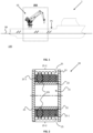
- Fig. 2 shows a winch 20 in accordance with an embodiment of the invention.
- the winch drum 21 comprises several known parts such as the winch drum cylinder 22 and the winch drum flanges 23. This is all considered known to the person skilled in the art.
- the hoisting rope 25 comprises a first part 25-1 that is connected to a second part 25-2.
- the first part 25-1 that is located on the inner side 20i of the winch drum 21, comprises a smaller diameter than the second part 25-2.
- Figs. 3-6 show different stages of a method in accordance with an embodiment of the invention. These figures effectively show part AA of Fig. 1 .
- the floating vessel 1 of Fig. 1 is shown, wherein an object 50 (a load) has been vertically suspended using suspension ropes 51 in the crane 10 as illustrated.
- the crane 10 has a known configuration comprising a crane pedestal 11 to which a main boom 13 is pivotably mounted. Furthermore, a knuckle-boom 15 (or jib) is pivotably mounted to the main boom 13.
- the winch 20 is visible, which includes the hoisting rope 25, which is guided using a plurality of wire sheaves 17 to a boom tip 20e at the end of the knuckle-boom 15 as illustrated. So far, everything described is known in the field of cranes for offshore/subsea hoisting. What is special in the crane 10 of Fig. 3 is that the winch 20 with the hoisting rope 25 is the same as shown in Fig. 2 , having the respective first part 25-1 and second part 25-2, wherein first part 25-1 has the smallest diameter. In the stage of Fig.
- the second part 25-2 is still partially wound on the winch 20. This means that it is the second part 25-2, which carries the full load, i.e. full weight of the object 50 that is hanging in the air.
- the figure illustrates a surface S1 of the floating vessel 1 on a first position P1, where the object 50 was taken from, before it was vertically suspended in the crane 10. Furthermore, the object 50 has already been moved to a second position P2 different from the first position P1 as illustrated.
- the object 50 has been lowered such that it touches the surface 99 of the water 100.
- the second part 25-2 is still partially wound on the winch 20. This means that it is still the second part 25-2, which substantially carries the full load, i.e. full weight of the object 50 that is hanging in the air.
- the object 50 has been lowered such that it is partially submerged in the water 100.
- the arrows illustrate the water 100 that has been pushed away by the object 50, thereby creating upwardly-directed buoyancy forces.
- the weight (load) acting on the hoisting rope 25 is reduced by the buoyancy forces.
- the second part 25-2 is partially wound on the winch 20 in this embodiment.
- the main reason for this is that the effective weight of the object 50 (load) on the hoisting rope 25 is still larger than the minimum breakable load of the first part (not shown) of the hoisting rope 25.
- the object 50 has been lowered to underneath the surface 99 of the water 100, i.e. it is fully submerged.
- the crane 10 could be designed such that the second part 25-2 of the hoisting rope 25 is fully unwound as soon as the object is just fully submerged.
- the inventors have found out that it is safe to keep a certain safety margin, that is that the second part 25-2, should preferably not be fully unwound until the object 50 has reached a predefined depth under the surface 99 of the water 100.
- the transition region 25t may be a tapered region, but also other solutions are possible as will be shown in the next figures.
- Fig. 7 shows a first variant of a hoisting rope 25 in accordance with an embodiment of the invention.
- the first part 25-1 and the second part 25-2 are connected through a tapered transition region 25t as illustrated.
- the length of the transition region may vary and will also depend on the ratio between a (first) diameter d1 of the first region 25-1 and a (second) diameter d2 of the second region 25-2.
- Fig. 7 also illustrates what is meant by a first end 25fe of the second part 25-2 that is connected to the first part 25-1 (via the transition region 25t), and a further end 25se at the side of the object/load (not shown).
- FIG. 9 shows a third variant of a hoisting rope 25b in accordance with an embodiment of the invention.
- the first end 25fe and further end 25se of the second part 25-2 are defined in a similar manner as in Figs. 7 and 8 .
- This variant uses a technology which has been used in rope extension systems as known from patent application publication WO2010/093251A1 , owned by the same applicant.
- a steel rope is extended using a fibre rope from a further winch.
- This fibre rope comprises multiple segments that are connected together using a rope connector that holds spliced ends of the fibre rope segments.
- This rope connector 200 may conveniently be used to make the transition between the first part 25-1 and the second part 25-2 of the hoisting rope 25 as illustrated.
- This rope connector 200 may conveniently be used to make the transition between the first part 25-1 and the second part 25-2 of the hoisting rope 25 as illustrated.
Landscapes
- Engineering & Computer Science (AREA)
- Mechanical Engineering (AREA)
- Ocean & Marine Engineering (AREA)
- Aviation & Aerospace Engineering (AREA)
- Chemical & Material Sciences (AREA)
- Combustion & Propulsion (AREA)
- Jib Cranes (AREA)
Claims (13)
- Système (10) de levage pour lever un objet (50) suspendu à la verticale, le système (10) de levage présentant un treuil (20) présentant un tambour (21) de treuil avec un câble (25) de levage, dans lequel une première partie (25-1) du câble (25) de levage présente un premier diamètre (d1) et une deuxième partie (25-2) présente un deuxième diamètre (d2) qui est plus grand que le premier diamètre (d1), la première partie (25-1) étant reliée à une première extrémité (25fe) de la deuxième partie (25-2), dans lequel la première partie (25-1) est une partie interne (20i) sur le tambour (21) de treuil lorsque le tambour (21) de treuil est complètement enroulé, dans lequel la deuxième partie (25-2) présente une autre extrémité (25se) qui peut être reliée à l'objet (50) pour lever l'objet (50), caractérisé en ce que un rapport entre le premier diamètre (d1) et le deuxième diamètre (d2) est choisi de telle sorte que la charge de rupture minimale de la première partie (25-1) diffère de moins d'un facteur de quatre par rapport à la charge de rupture minimale de la deuxième partie (25-2), et préférablement de moins d'un facteur de trois.
- Système (10) de levage selon la revendication 1, dans lequel la longueur de la deuxième partie (25-2) du câble (25) de levage est choisie de telle sorte que, alors que, en utilisation fonctionnelle, l'objet (50) est suspendu dans le câble (25) de levage et touche l'eau (100), la deuxième partie (25-2) reste enroulée autour du tambour (21) de treuil avec au moins un enroulement prédéfini d'enroulements et s'étire tout du long depuis le tambour (21) de treuil le long du système (10) de levage et vers le bas jusqu'à l'autre extrémité (25se) du câble (25) de levage près de l'eau (100).
- Système (10) de levage selon la revendication 1 ou la revendication 2, dans lequel la première partie (25-1) et la deuxième partie (25-2) sont reliées par le biais d'une région de transition conique (25t).
- Système (10) de levage selon la revendication 2 ou la revendication 3, dans lequel la deuxième partie (25-2) présente une longueur entre 10 et 500 mètres, et préférablement entre 10 et 400 mètres, et encore plus préférablement entre 10 et 300 mètres.
- Système (10) de levage selon l'une quelconque des revendications précédentes, dans lequel la première partie (25-1) présente une longueur entre 10 et 10 000 mètres, et préférablement entre 20 et 5000 mètres, et encore plus préférablement entre 30 et 3000 mètres.
- Système (10) de levage selon l'une quelconque des revendications précédentes, dans lequel le premier diamètre (d1) de la première partie (25-1) du câble (25) de levage est entre 5 mm et 300 mm.
- Système (10) de levage selon l'une quelconque des revendications précédentes, dans lequel le deuxième diamètre (d2) de la deuxième partie (25-2) du câble (25) de levage est entre 25 mm et 500 mm.
- Procédé de levage d'un objet (50) suspendu à la verticale avec un système (10) de levage conformément à l'une quelconque des revendications précédentes.
- Procédé selon la revendication 8, dans lequel le procédé comprend une étape de levage de l'objet (50) soit dans soit depuis l'eau (100), d'une manière telle que la deuxième partie (25-2) du tambour (21) de treuil est toujours au moins partiellement enroulée sur le tambour (21) de treuil avant que l'objet (50) ne soit soulevé hors de l'eau (100) pendant le levage de l'objet (50), et que la première partie (25-1) n'est pas déroulée du tambour (21) de treuil avant que l'objet (50) ne soit totalement immergé dans l'eau pendant l'abaissement de l'objet (50).
- Procédé selon la revendication 9, dans lequel le procédé comprend les étapes consistant à :- monter un objet (50) reposant sur une première surface (S1) à une première position (P1) jusqu'à l'autre extrémité (25se) du câble (25) de levage, dans lequel la deuxième partie (25-2) a été partiellement déroulée du tambour (21) de treuil ;- lever l'objet (50) avec le treuil (20) depuis la première surface (S1) pour suspendre l'objet (50) dans le câble (25) de levage, dans lequel la deuxième partie (25-2) reste partiellement enroulée sur le tambour (21) de treuil, dans lequel pendant le levage la deuxième partie (25-2) porte le poids total de l'objet (50) ;- déplacer le système (10) de levage jusqu'à une deuxième position (P2) au-dessus de l'eau (100), dans lequel la deuxième partie (25-2) porte le poids total de l'objet (50) ;- abaisser l'objet avec le treuil (20) jusqu'à ce qu'il soit totalement immergé dans l'eau (100), dans lequel la deuxième partie (25-2) reste au moins partiellement enroulée sur le tambour (21) de treuil jusqu'à ce que l'objet (50) soit totalement immergé ; et- abaisser encore l'objet avec le treuil (20) dans l'eau (100) déroulant complètement la deuxième partie (25-2) et déroulant au moins partiellement la première partie (25-1) du tambour (21) de treuil, dans lequel la première partie (25-1) est exposée à un poids effectif réduit de l'objet (50) en raison de forces de flottabilité agissant par l'eau (100) sur l'objet (50) et le câble (25) de levage.
- Procédé selon la revendication 10, dans lequel, à l'étape d'abaissement de l'objet (50), au moins un nombre prédéfini d'enroulements de la deuxième partie (25-2) restent sur le tambour (21) de treuil jusqu'à ce que l'objet (50) soit exactement totalement immergé.
- Procédé selon la revendication 9, dans lequel le procédé comprend les étapes consistant à :- monter un objet (50) qui est immergé dans l'eau (100) à une deuxième position (P2) jusqu'à l'autre extrémité (25se) du câble (25) de levage, dans lequel la deuxième partie (25-2) a été totalement déroulée et la première partie (25-1) a été au moins partiellement déroulée du tambour (21) de treuil ;- lever l'objet (50) avec le treuil (20) pour suspendre l'objet (50) dans le câble (25) de levage, dans lequel la première partie (25-1) est enroulée sur le tambour (21) de treuil jusqu'à ce que la deuxième partie (25-2) soit partiellement enroulée sur le tambour (21) de treuil alors que l'objet (50) est toujours immergé, dans lequel pendant le levage la première partie (25-1) porte un poids effectif réduit de l'objet (50) en raison de forces de flottabilité agissant par l'eau (100) sur l'objet (50) et le câble (25) de levage ;- lever encore l'objet (50) avec le treuil (20) hors de l'eau (100), dans lequel la deuxième partie (25-2) est encore enroulée sur le tambour (21) de treuil ;- déplacer le système (10) de levage jusqu'à une première position (P1), dans lequel la deuxième partie (25-2) porte le poids total de l'objet (50) ; et- abaisser l'objet avec le treuil (20) pour qu'il touche une première surface (S1) à la première position (P1), dans lequel toujours uniquement la deuxième partie (25-2) est partiellement déroulée du tambour (21) de treuil.
- Procédé selon la revendication 12, dans lequel, à l'étape de levage de l'objet (50), au moins un nombre prédéfini d'enroulements de la deuxième partie (25-2) sont enroulés sur le tambour (21) de treuil avant que l'objet (50) ne soit plus totalement immergé.
Priority Applications (2)
| Application Number | Priority Date | Filing Date | Title |
|---|---|---|---|
| EP20153151.4A EP3854746B1 (fr) | 2020-01-22 | 2020-01-22 | Système de levage et procédé de levage d'un objet suspendu verticalement |
| US17/152,226 US11312452B2 (en) | 2020-01-22 | 2021-01-19 | Hoisting system and method for hoisting a vertically-suspended object |
Applications Claiming Priority (1)
| Application Number | Priority Date | Filing Date | Title |
|---|---|---|---|
| EP20153151.4A EP3854746B1 (fr) | 2020-01-22 | 2020-01-22 | Système de levage et procédé de levage d'un objet suspendu verticalement |
Publications (2)
| Publication Number | Publication Date |
|---|---|
| EP3854746A1 EP3854746A1 (fr) | 2021-07-28 |
| EP3854746B1 true EP3854746B1 (fr) | 2024-12-18 |
Family
ID=69187674
Family Applications (1)
| Application Number | Title | Priority Date | Filing Date |
|---|---|---|---|
| EP20153151.4A Active EP3854746B1 (fr) | 2020-01-22 | 2020-01-22 | Système de levage et procédé de levage d'un objet suspendu verticalement |
Country Status (2)
| Country | Link |
|---|---|
| US (1) | US11312452B2 (fr) |
| EP (1) | EP3854746B1 (fr) |
Families Citing this family (2)
| Publication number | Priority date | Publication date | Assignee | Title |
|---|---|---|---|---|
| FI130419B (fi) * | 2020-11-23 | 2023-08-21 | Konecranes Global Oy | Köysinostin |
| CN114722460B (zh) * | 2022-03-16 | 2025-07-29 | 中铁建城建交通发展有限公司 | 绞磨选用方法、装置、设备及存储介质 |
Citations (1)
| Publication number | Priority date | Publication date | Assignee | Title |
|---|---|---|---|---|
| US20150274260A1 (en) * | 2014-02-20 | 2015-10-01 | Woods Hole Oceanographic Institution | Mechanical tether system for a submersible vehicle |
Family Cites Families (7)
| Publication number | Priority date | Publication date | Assignee | Title |
|---|---|---|---|---|
| US3809334A (en) * | 1972-11-06 | 1974-05-07 | United Aircraft Corp | Winch system for helicopter |
| US6536743B2 (en) * | 2001-05-09 | 2003-03-25 | Dynacon, Inc. | Fixed umbilical cable flotation docking head |
| US6752100B2 (en) * | 2002-05-28 | 2004-06-22 | Shell Oil Company | Apparatuses and methods of deploying and installing subsea equipment |
| US7933165B2 (en) * | 2008-09-03 | 2011-04-26 | Fairfield Industries Incorporated | Connector for seismic cable |
| NO333202B1 (no) | 2009-02-16 | 2013-04-08 | Nat Oilwell Varco Norway As | Fremgangsmate og anordning for a heise et kolli fra en kran |
| US9102390B2 (en) * | 2011-09-16 | 2015-08-11 | Nigk Corporation | Underwater rising/falling device |
| CN110382346B (zh) * | 2017-01-16 | 2021-10-01 | 伊特里克公司 | 深水升降系统以及方法 |
-
2020
- 2020-01-22 EP EP20153151.4A patent/EP3854746B1/fr active Active
-
2021
- 2021-01-19 US US17/152,226 patent/US11312452B2/en active Active
Patent Citations (1)
| Publication number | Priority date | Publication date | Assignee | Title |
|---|---|---|---|---|
| US20150274260A1 (en) * | 2014-02-20 | 2015-10-01 | Woods Hole Oceanographic Institution | Mechanical tether system for a submersible vehicle |
Also Published As
| Publication number | Publication date |
|---|---|
| US11312452B2 (en) | 2022-04-26 |
| EP3854746A1 (fr) | 2021-07-28 |
| US20210221659A1 (en) | 2021-07-22 |
Similar Documents
| Publication | Publication Date | Title |
|---|---|---|
| CN110382346B (zh) | 深水升降系统以及方法 | |
| CN104520226B (zh) | 起重船 | |
| EP2477927B1 (fr) | Dispositif de levage | |
| EP2349906B1 (fr) | Opérations de levage en mer | |
| EP2797830B1 (fr) | Grue à flèche double déport en eaux profondes | |
| EP2379404B1 (fr) | Méthode et appareil pour soulever un poids | |
| CN101500930A (zh) | 直接作用单滑轮主动/被动升沉补偿器 | |
| EP2986550B1 (fr) | Appareil porte-charge et procédé | |
| WO2010093251A1 (fr) | Procédé et dispositif pour lever un article à l'aide d'une grue | |
| KR102511234B1 (ko) | 해상 리프팅 크레인 | |
| EP3854746B1 (fr) | Système de levage et procédé de levage d'un objet suspendu verticalement | |
| US8905381B2 (en) | Hoisting assembly | |
| CN117403864B (zh) | 一种用于自升式钻井平台桩腿维护的吊篮装置 | |
| EP3237718B1 (fr) | Système pour lever une charge sur une plate-forme de forage en mer | |
| HK1215563B (en) | Load bearing apparatus and method | |
| CN111453633A (zh) | 一种用于海上浮吊的稳索系统 |
Legal Events
| Date | Code | Title | Description |
|---|---|---|---|
| PUAI | Public reference made under article 153(3) epc to a published international application that has entered the european phase |
Free format text: ORIGINAL CODE: 0009012 |
|
| STAA | Information on the status of an ep patent application or granted ep patent |
Free format text: STATUS: THE APPLICATION HAS BEEN PUBLISHED |
|
| AK | Designated contracting states |
Kind code of ref document: A1 Designated state(s): AL AT BE BG CH CY CZ DE DK EE ES FI FR GB GR HR HU IE IS IT LI LT LU LV MC MK MT NL NO PL PT RO RS SE SI SK SM TR |
|
| STAA | Information on the status of an ep patent application or granted ep patent |
Free format text: STATUS: REQUEST FOR EXAMINATION WAS MADE |
|
| 17P | Request for examination filed |
Effective date: 20220105 |
|
| RBV | Designated contracting states (corrected) |
Designated state(s): AL AT BE BG CH CY CZ DE DK EE ES FI FR GB GR HR HU IE IS IT LI LT LU LV MC MK MT NL NO PL PT RO RS SE SI SK SM TR |
|
| RAP1 | Party data changed (applicant data changed or rights of an application transferred) |
Owner name: NOV INTERNATIONAL HOLDINGS C.V. |
|
| RAP1 | Party data changed (applicant data changed or rights of an application transferred) |
Owner name: GRANT PRIDECO, INC. |
|
| STAA | Information on the status of an ep patent application or granted ep patent |
Free format text: STATUS: EXAMINATION IS IN PROGRESS |
|
| 17Q | First examination report despatched |
Effective date: 20230525 |
|
| P01 | Opt-out of the competence of the unified patent court (upc) registered |
Effective date: 20230530 |
|
| GRAP | Despatch of communication of intention to grant a patent |
Free format text: ORIGINAL CODE: EPIDOSNIGR1 |
|
| STAA | Information on the status of an ep patent application or granted ep patent |
Free format text: STATUS: GRANT OF PATENT IS INTENDED |
|
| INTG | Intention to grant announced |
Effective date: 20240730 |
|
| GRAS | Grant fee paid |
Free format text: ORIGINAL CODE: EPIDOSNIGR3 |
|
| GRAA | (expected) grant |
Free format text: ORIGINAL CODE: 0009210 |
|
| STAA | Information on the status of an ep patent application or granted ep patent |
Free format text: STATUS: THE PATENT HAS BEEN GRANTED |
|
| AK | Designated contracting states |
Kind code of ref document: B1 Designated state(s): AL AT BE BG CH CY CZ DE DK EE ES FI FR GB GR HR HU IE IS IT LI LT LU LV MC MK MT NL NO PL PT RO RS SE SI SK SM TR |
|
| REG | Reference to a national code |
Ref country code: CH Ref legal event code: EP |
|
| REG | Reference to a national code |
Ref country code: DE Ref legal event code: R096 Ref document number: 602020043214 Country of ref document: DE |
|
| REG | Reference to a national code |
Ref country code: IE Ref legal event code: FG4D |
|
| PGFP | Annual fee paid to national office [announced via postgrant information from national office to epo] |
Ref country code: FR Payment date: 20241223 Year of fee payment: 6 |
|
| REG | Reference to a national code |
Ref country code: NL Ref legal event code: FP |
|
| REG | Reference to a national code |
Ref country code: LT Ref legal event code: MG9D |
|
| PG25 | Lapsed in a contracting state [announced via postgrant information from national office to epo] |
Ref country code: HR Free format text: LAPSE BECAUSE OF FAILURE TO SUBMIT A TRANSLATION OF THE DESCRIPTION OR TO PAY THE FEE WITHIN THE PRESCRIBED TIME-LIMIT Effective date: 20241218 |
|
| PGFP | Annual fee paid to national office [announced via postgrant information from national office to epo] |
Ref country code: DE Payment date: 20241224 Year of fee payment: 6 |
|
| PG25 | Lapsed in a contracting state [announced via postgrant information from national office to epo] |
Ref country code: FI Free format text: LAPSE BECAUSE OF FAILURE TO SUBMIT A TRANSLATION OF THE DESCRIPTION OR TO PAY THE FEE WITHIN THE PRESCRIBED TIME-LIMIT Effective date: 20241218 |
|
| PG25 | Lapsed in a contracting state [announced via postgrant information from national office to epo] |
Ref country code: BG Free format text: LAPSE BECAUSE OF FAILURE TO SUBMIT A TRANSLATION OF THE DESCRIPTION OR TO PAY THE FEE WITHIN THE PRESCRIBED TIME-LIMIT Effective date: 20241218 |
|
| PG25 | Lapsed in a contracting state [announced via postgrant information from national office to epo] |
Ref country code: LV Free format text: LAPSE BECAUSE OF FAILURE TO SUBMIT A TRANSLATION OF THE DESCRIPTION OR TO PAY THE FEE WITHIN THE PRESCRIBED TIME-LIMIT Effective date: 20241218 Ref country code: GR Free format text: LAPSE BECAUSE OF FAILURE TO SUBMIT A TRANSLATION OF THE DESCRIPTION OR TO PAY THE FEE WITHIN THE PRESCRIBED TIME-LIMIT Effective date: 20250319 |
|
| PG25 | Lapsed in a contracting state [announced via postgrant information from national office to epo] |
Ref country code: RS Free format text: LAPSE BECAUSE OF FAILURE TO SUBMIT A TRANSLATION OF THE DESCRIPTION OR TO PAY THE FEE WITHIN THE PRESCRIBED TIME-LIMIT Effective date: 20250318 |
|
| REG | Reference to a national code |
Ref country code: AT Ref legal event code: MK05 Ref document number: 1752125 Country of ref document: AT Kind code of ref document: T Effective date: 20241218 |
|
| PG25 | Lapsed in a contracting state [announced via postgrant information from national office to epo] |
Ref country code: SM Free format text: LAPSE BECAUSE OF FAILURE TO SUBMIT A TRANSLATION OF THE DESCRIPTION OR TO PAY THE FEE WITHIN THE PRESCRIBED TIME-LIMIT Effective date: 20241218 |
|
| PG25 | Lapsed in a contracting state [announced via postgrant information from national office to epo] |
Ref country code: PL Free format text: LAPSE BECAUSE OF FAILURE TO SUBMIT A TRANSLATION OF THE DESCRIPTION OR TO PAY THE FEE WITHIN THE PRESCRIBED TIME-LIMIT Effective date: 20241218 |
|
| PG25 | Lapsed in a contracting state [announced via postgrant information from national office to epo] |
Ref country code: ES Free format text: LAPSE BECAUSE OF FAILURE TO SUBMIT A TRANSLATION OF THE DESCRIPTION OR TO PAY THE FEE WITHIN THE PRESCRIBED TIME-LIMIT Effective date: 20241218 |
|
| PG25 | Lapsed in a contracting state [announced via postgrant information from national office to epo] |
Ref country code: IS Free format text: LAPSE BECAUSE OF FAILURE TO SUBMIT A TRANSLATION OF THE DESCRIPTION OR TO PAY THE FEE WITHIN THE PRESCRIBED TIME-LIMIT Effective date: 20250418 |
|
| PG25 | Lapsed in a contracting state [announced via postgrant information from national office to epo] |
Ref country code: PT Free format text: LAPSE BECAUSE OF FAILURE TO SUBMIT A TRANSLATION OF THE DESCRIPTION OR TO PAY THE FEE WITHIN THE PRESCRIBED TIME-LIMIT Effective date: 20250421 |
|
| PG25 | Lapsed in a contracting state [announced via postgrant information from national office to epo] |
Ref country code: EE Free format text: LAPSE BECAUSE OF FAILURE TO SUBMIT A TRANSLATION OF THE DESCRIPTION OR TO PAY THE FEE WITHIN THE PRESCRIBED TIME-LIMIT Effective date: 20241218 |
|
| PG25 | Lapsed in a contracting state [announced via postgrant information from national office to epo] |
Ref country code: RO Free format text: LAPSE BECAUSE OF FAILURE TO SUBMIT A TRANSLATION OF THE DESCRIPTION OR TO PAY THE FEE WITHIN THE PRESCRIBED TIME-LIMIT Effective date: 20241218 Ref country code: AT Free format text: LAPSE BECAUSE OF FAILURE TO SUBMIT A TRANSLATION OF THE DESCRIPTION OR TO PAY THE FEE WITHIN THE PRESCRIBED TIME-LIMIT Effective date: 20241218 |
|
| PG25 | Lapsed in a contracting state [announced via postgrant information from national office to epo] |
Ref country code: SK Free format text: LAPSE BECAUSE OF FAILURE TO SUBMIT A TRANSLATION OF THE DESCRIPTION OR TO PAY THE FEE WITHIN THE PRESCRIBED TIME-LIMIT Effective date: 20241218 |
|
| PG25 | Lapsed in a contracting state [announced via postgrant information from national office to epo] |
Ref country code: CZ Free format text: LAPSE BECAUSE OF FAILURE TO SUBMIT A TRANSLATION OF THE DESCRIPTION OR TO PAY THE FEE WITHIN THE PRESCRIBED TIME-LIMIT Effective date: 20241218 |
|
| PG25 | Lapsed in a contracting state [announced via postgrant information from national office to epo] |
Ref country code: IT Free format text: LAPSE BECAUSE OF FAILURE TO SUBMIT A TRANSLATION OF THE DESCRIPTION OR TO PAY THE FEE WITHIN THE PRESCRIBED TIME-LIMIT Effective date: 20241218 |
|
| REG | Reference to a national code |
Ref country code: CH Ref legal event code: PL |
|
| PG25 | Lapsed in a contracting state [announced via postgrant information from national office to epo] |
Ref country code: SE Free format text: LAPSE BECAUSE OF FAILURE TO SUBMIT A TRANSLATION OF THE DESCRIPTION OR TO PAY THE FEE WITHIN THE PRESCRIBED TIME-LIMIT Effective date: 20241218 |
|
| PG25 | Lapsed in a contracting state [announced via postgrant information from national office to epo] |
Ref country code: LU Free format text: LAPSE BECAUSE OF NON-PAYMENT OF DUE FEES Effective date: 20250122 Ref country code: MC Free format text: LAPSE BECAUSE OF FAILURE TO SUBMIT A TRANSLATION OF THE DESCRIPTION OR TO PAY THE FEE WITHIN THE PRESCRIBED TIME-LIMIT Effective date: 20241218 |
|
| REG | Reference to a national code |
Ref country code: DE Ref legal event code: R097 Ref document number: 602020043214 Country of ref document: DE |
|
| PG25 | Lapsed in a contracting state [announced via postgrant information from national office to epo] |
Ref country code: DK Free format text: LAPSE BECAUSE OF FAILURE TO SUBMIT A TRANSLATION OF THE DESCRIPTION OR TO PAY THE FEE WITHIN THE PRESCRIBED TIME-LIMIT Effective date: 20241218 |
|
| PG25 | Lapsed in a contracting state [announced via postgrant information from national office to epo] |
Ref country code: BE Free format text: LAPSE BECAUSE OF NON-PAYMENT OF DUE FEES Effective date: 20250131 |
|
| PG25 | Lapsed in a contracting state [announced via postgrant information from national office to epo] |
Ref country code: CH Free format text: LAPSE BECAUSE OF NON-PAYMENT OF DUE FEES Effective date: 20250131 |
|
| REG | Reference to a national code |
Ref country code: BE Ref legal event code: MM Effective date: 20250131 |
|
| PLBE | No opposition filed within time limit |
Free format text: ORIGINAL CODE: 0009261 |
|
| STAA | Information on the status of an ep patent application or granted ep patent |
Free format text: STATUS: NO OPPOSITION FILED WITHIN TIME LIMIT |
|
| 26N | No opposition filed |
Effective date: 20250919 |
|
| PGFP | Annual fee paid to national office [announced via postgrant information from national office to epo] |
Ref country code: GB Payment date: 20251204 Year of fee payment: 7 |
|
| PGFP | Annual fee paid to national office [announced via postgrant information from national office to epo] |
Ref country code: NL Payment date: 20251215 Year of fee payment: 7 |
|
| PG25 | Lapsed in a contracting state [announced via postgrant information from national office to epo] |
Ref country code: IE Free format text: LAPSE BECAUSE OF NON-PAYMENT OF DUE FEES Effective date: 20250122 |
|
| PGFP | Annual fee paid to national office [announced via postgrant information from national office to epo] |
Ref country code: NO Payment date: 20260109 Year of fee payment: 7 |