EP3854898B1 - Corps fritté en nitrure de bore cubique et outil de coupe le contenant - Google Patents
Corps fritté en nitrure de bore cubique et outil de coupe le contenant Download PDFInfo
- Publication number
- EP3854898B1 EP3854898B1 EP19862667.3A EP19862667A EP3854898B1 EP 3854898 B1 EP3854898 B1 EP 3854898B1 EP 19862667 A EP19862667 A EP 19862667A EP 3854898 B1 EP3854898 B1 EP 3854898B1
- Authority
- EP
- European Patent Office
- Prior art keywords
- boron nitride
- cubic boron
- powder
- sintered material
- nitride sintered
- Prior art date
- Legal status (The legal status is an assumption and is not a legal conclusion. Google has not performed a legal analysis and makes no representation as to the accuracy of the status listed.)
- Active
Links
Images

Classifications
-
- C—CHEMISTRY; METALLURGY
- C01—INORGANIC CHEMISTRY
- C01B—NON-METALLIC ELEMENTS; COMPOUNDS THEREOF; METALLOIDS OR COMPOUNDS THEREOF NOT COVERED BY SUBCLASS C01C
- C01B21/00—Nitrogen; Compounds thereof
- C01B21/06—Binary compounds of nitrogen with metals, with silicon, or with boron, or with carbon, i.e. nitrides; Compounds of nitrogen with more than one metal, silicon or boron
- C01B21/064—Binary compounds of nitrogen with metals, with silicon, or with boron, or with carbon, i.e. nitrides; Compounds of nitrogen with more than one metal, silicon or boron with boron
- C01B21/0648—After-treatment, e.g. grinding, purification
-
- C—CHEMISTRY; METALLURGY
- C04—CEMENTS; CONCRETE; ARTIFICIAL STONE; CERAMICS; REFRACTORIES
- C04B—LIME, MAGNESIA; SLAG; CEMENTS; COMPOSITIONS THEREOF, e.g. MORTARS, CONCRETE OR LIKE BUILDING MATERIALS; ARTIFICIAL STONE; CERAMICS; REFRACTORIES; TREATMENT OF NATURAL STONE
- C04B35/00—Shaped ceramic products characterised by their composition; Ceramics compositions; Processing powders of inorganic compounds preparatory to the manufacturing of ceramic products
- C04B35/515—Shaped ceramic products characterised by their composition; Ceramics compositions; Processing powders of inorganic compounds preparatory to the manufacturing of ceramic products based on non-oxide ceramics
- C04B35/58—Shaped ceramic products characterised by their composition; Ceramics compositions; Processing powders of inorganic compounds preparatory to the manufacturing of ceramic products based on non-oxide ceramics based on borides, nitrides, i.e. nitrides, oxynitrides, carbonitrides or oxycarbonitrides or silicides
- C04B35/583—Shaped ceramic products characterised by their composition; Ceramics compositions; Processing powders of inorganic compounds preparatory to the manufacturing of ceramic products based on non-oxide ceramics based on borides, nitrides, i.e. nitrides, oxynitrides, carbonitrides or oxycarbonitrides or silicides based on boron nitride
- C04B35/5831—Shaped ceramic products characterised by their composition; Ceramics compositions; Processing powders of inorganic compounds preparatory to the manufacturing of ceramic products based on non-oxide ceramics based on borides, nitrides, i.e. nitrides, oxynitrides, carbonitrides or oxycarbonitrides or silicides based on boron nitride based on cubic boron nitrides or Wurtzitic boron nitrides, including crystal structure transformation of powder
-
- C—CHEMISTRY; METALLURGY
- C04—CEMENTS; CONCRETE; ARTIFICIAL STONE; CERAMICS; REFRACTORIES
- C04B—LIME, MAGNESIA; SLAG; CEMENTS; COMPOSITIONS THEREOF, e.g. MORTARS, CONCRETE OR LIKE BUILDING MATERIALS; ARTIFICIAL STONE; CERAMICS; REFRACTORIES; TREATMENT OF NATURAL STONE
- C04B35/00—Shaped ceramic products characterised by their composition; Ceramics compositions; Processing powders of inorganic compounds preparatory to the manufacturing of ceramic products
- C04B35/622—Forming processes; Processing powders of inorganic compounds preparatory to the manufacturing of ceramic products
- C04B35/64—Burning or sintering processes
- C04B35/645—Pressure sintering
-
- C—CHEMISTRY; METALLURGY
- C22—METALLURGY; FERROUS OR NON-FERROUS ALLOYS; TREATMENT OF ALLOYS OR NON-FERROUS METALS
- C22C—ALLOYS
- C22C1/00—Making non-ferrous alloys
- C22C1/04—Making non-ferrous alloys by powder metallurgy
- C22C1/05—Mixtures of metal powder with non-metallic powder
-
- C—CHEMISTRY; METALLURGY
- C22—METALLURGY; FERROUS OR NON-FERROUS ALLOYS; TREATMENT OF ALLOYS OR NON-FERROUS METALS
- C22C—ALLOYS
- C22C1/00—Making non-ferrous alloys
- C22C1/04—Making non-ferrous alloys by powder metallurgy
- C22C1/05—Mixtures of metal powder with non-metallic powder
- C22C1/051—Making hard metals based on borides, carbides, nitrides, oxides or silicides; Preparation of the powder mixture used as the starting material therefor
-
- C—CHEMISTRY; METALLURGY
- C22—METALLURGY; FERROUS OR NON-FERROUS ALLOYS; TREATMENT OF ALLOYS OR NON-FERROUS METALS
- C22C—ALLOYS
- C22C29/00—Alloys based on carbides, oxides, nitrides, borides, or silicides, e.g. cermets, or other metal compounds, e.g. oxynitrides, sulfides
- C22C29/02—Alloys based on carbides, oxides, nitrides, borides, or silicides, e.g. cermets, or other metal compounds, e.g. oxynitrides, sulfides based on carbides or carbonitrides
-
- C—CHEMISTRY; METALLURGY
- C22—METALLURGY; FERROUS OR NON-FERROUS ALLOYS; TREATMENT OF ALLOYS OR NON-FERROUS METALS
- C22C—ALLOYS
- C22C29/00—Alloys based on carbides, oxides, nitrides, borides, or silicides, e.g. cermets, or other metal compounds, e.g. oxynitrides, sulfides
- C22C29/16—Alloys based on carbides, oxides, nitrides, borides, or silicides, e.g. cermets, or other metal compounds, e.g. oxynitrides, sulfides based on nitrides
-
- B—PERFORMING OPERATIONS; TRANSPORTING
- B22—CASTING; POWDER METALLURGY
- B22F—WORKING METALLIC POWDER; MANUFACTURE OF ARTICLES FROM METALLIC POWDER; MAKING METALLIC POWDER; APPARATUS OR DEVICES SPECIALLY ADAPTED FOR METALLIC POWDER
- B22F5/00—Manufacture of workpieces or articles from metallic powder characterised by the special shape of the product
- B22F2005/001—Cutting tools, earth boring or grinding tool other than table ware
-
- B—PERFORMING OPERATIONS; TRANSPORTING
- B22—CASTING; POWDER METALLURGY
- B22F—WORKING METALLIC POWDER; MANUFACTURE OF ARTICLES FROM METALLIC POWDER; MAKING METALLIC POWDER; APPARATUS OR DEVICES SPECIALLY ADAPTED FOR METALLIC POWDER
- B22F2998/00—Supplementary information concerning processes or compositions relating to powder metallurgy
- B22F2998/10—Processes characterised by the sequence of their steps
-
- B—PERFORMING OPERATIONS; TRANSPORTING
- B23—MACHINE TOOLS; METAL-WORKING NOT OTHERWISE PROVIDED FOR
- B23B—TURNING; BORING
- B23B27/00—Tools for turning or boring machines; Tools of a similar kind in general; Accessories therefor
- B23B27/14—Cutting tools of which the bits or tips or cutting inserts are of special material
-
- C—CHEMISTRY; METALLURGY
- C01—INORGANIC CHEMISTRY
- C01P—INDEXING SCHEME RELATING TO STRUCTURAL AND PHYSICAL ASPECTS OF SOLID INORGANIC COMPOUNDS
- C01P2004/00—Particle morphology
- C01P2004/30—Particle morphology extending in three dimensions
- C01P2004/38—Particle morphology extending in three dimensions cube-like
-
- C—CHEMISTRY; METALLURGY
- C01—INORGANIC CHEMISTRY
- C01P—INDEXING SCHEME RELATING TO STRUCTURAL AND PHYSICAL ASPECTS OF SOLID INORGANIC COMPOUNDS
- C01P2004/00—Particle morphology
- C01P2004/60—Particles characterised by their size
- C01P2004/64—Nanometer sized, i.e. from 1-100 nanometer
-
- C—CHEMISTRY; METALLURGY
- C01—INORGANIC CHEMISTRY
- C01P—INDEXING SCHEME RELATING TO STRUCTURAL AND PHYSICAL ASPECTS OF SOLID INORGANIC COMPOUNDS
- C01P2006/00—Physical properties of inorganic compounds
- C01P2006/80—Compositional purity
-
- C—CHEMISTRY; METALLURGY
- C04—CEMENTS; CONCRETE; ARTIFICIAL STONE; CERAMICS; REFRACTORIES
- C04B—LIME, MAGNESIA; SLAG; CEMENTS; COMPOSITIONS THEREOF, e.g. MORTARS, CONCRETE OR LIKE BUILDING MATERIALS; ARTIFICIAL STONE; CERAMICS; REFRACTORIES; TREATMENT OF NATURAL STONE
- C04B2235/00—Aspects relating to ceramic starting mixtures or sintered ceramic products
- C04B2235/02—Composition of constituents of the starting material or of secondary phases of the final product
- C04B2235/30—Constituents and secondary phases not being of a fibrous nature
- C04B2235/38—Non-oxide ceramic constituents or additives
- C04B2235/3817—Carbides
- C04B2235/3839—Refractory metal carbides
- C04B2235/3847—Tungsten carbides
-
- C—CHEMISTRY; METALLURGY
- C04—CEMENTS; CONCRETE; ARTIFICIAL STONE; CERAMICS; REFRACTORIES
- C04B—LIME, MAGNESIA; SLAG; CEMENTS; COMPOSITIONS THEREOF, e.g. MORTARS, CONCRETE OR LIKE BUILDING MATERIALS; ARTIFICIAL STONE; CERAMICS; REFRACTORIES; TREATMENT OF NATURAL STONE
- C04B2235/00—Aspects relating to ceramic starting mixtures or sintered ceramic products
- C04B2235/02—Composition of constituents of the starting material or of secondary phases of the final product
- C04B2235/30—Constituents and secondary phases not being of a fibrous nature
- C04B2235/40—Metallic constituents or additives not added as binding phase
- C04B2235/402—Aluminium
-
- C—CHEMISTRY; METALLURGY
- C04—CEMENTS; CONCRETE; ARTIFICIAL STONE; CERAMICS; REFRACTORIES
- C04B—LIME, MAGNESIA; SLAG; CEMENTS; COMPOSITIONS THEREOF, e.g. MORTARS, CONCRETE OR LIKE BUILDING MATERIALS; ARTIFICIAL STONE; CERAMICS; REFRACTORIES; TREATMENT OF NATURAL STONE
- C04B2235/00—Aspects relating to ceramic starting mixtures or sintered ceramic products
- C04B2235/02—Composition of constituents of the starting material or of secondary phases of the final product
- C04B2235/30—Constituents and secondary phases not being of a fibrous nature
- C04B2235/40—Metallic constituents or additives not added as binding phase
- C04B2235/405—Iron group metals
-
- C—CHEMISTRY; METALLURGY
- C04—CEMENTS; CONCRETE; ARTIFICIAL STONE; CERAMICS; REFRACTORIES
- C04B—LIME, MAGNESIA; SLAG; CEMENTS; COMPOSITIONS THEREOF, e.g. MORTARS, CONCRETE OR LIKE BUILDING MATERIALS; ARTIFICIAL STONE; CERAMICS; REFRACTORIES; TREATMENT OF NATURAL STONE
- C04B2235/00—Aspects relating to ceramic starting mixtures or sintered ceramic products
- C04B2235/02—Composition of constituents of the starting material or of secondary phases of the final product
- C04B2235/30—Constituents and secondary phases not being of a fibrous nature
- C04B2235/48—Organic compounds becoming part of a ceramic after heat treatment, e.g. carbonising phenol resins
-
- C—CHEMISTRY; METALLURGY
- C04—CEMENTS; CONCRETE; ARTIFICIAL STONE; CERAMICS; REFRACTORIES
- C04B—LIME, MAGNESIA; SLAG; CEMENTS; COMPOSITIONS THEREOF, e.g. MORTARS, CONCRETE OR LIKE BUILDING MATERIALS; ARTIFICIAL STONE; CERAMICS; REFRACTORIES; TREATMENT OF NATURAL STONE
- C04B2235/00—Aspects relating to ceramic starting mixtures or sintered ceramic products
- C04B2235/02—Composition of constituents of the starting material or of secondary phases of the final product
- C04B2235/50—Constituents or additives of the starting mixture chosen for their shape or used because of their shape or their physical appearance
- C04B2235/54—Particle size related information
- C04B2235/5418—Particle size related information expressed by the size of the particles or aggregates thereof
- C04B2235/5436—Particle size related information expressed by the size of the particles or aggregates thereof micrometer sized, i.e. from 1 to 100 micron
-
- C—CHEMISTRY; METALLURGY
- C04—CEMENTS; CONCRETE; ARTIFICIAL STONE; CERAMICS; REFRACTORIES
- C04B—LIME, MAGNESIA; SLAG; CEMENTS; COMPOSITIONS THEREOF, e.g. MORTARS, CONCRETE OR LIKE BUILDING MATERIALS; ARTIFICIAL STONE; CERAMICS; REFRACTORIES; TREATMENT OF NATURAL STONE
- C04B2235/00—Aspects relating to ceramic starting mixtures or sintered ceramic products
- C04B2235/02—Composition of constituents of the starting material or of secondary phases of the final product
- C04B2235/50—Constituents or additives of the starting mixture chosen for their shape or used because of their shape or their physical appearance
- C04B2235/54—Particle size related information
- C04B2235/5418—Particle size related information expressed by the size of the particles or aggregates thereof
- C04B2235/5454—Particle size related information expressed by the size of the particles or aggregates thereof nanometer sized, i.e. below 100 nm
-
- C—CHEMISTRY; METALLURGY
- C22—METALLURGY; FERROUS OR NON-FERROUS ALLOYS; TREATMENT OF ALLOYS OR NON-FERROUS METALS
- C22C—ALLOYS
- C22C26/00—Alloys containing diamond or cubic or wurtzitic boron nitride, fullerenes or carbon nanotubes
Definitions
- the present disclosure relates to a cubic boron nitride sintered material and a cutting tool including the cubic boron nitride sintered.
- a cubic boron nitride sintered material (hereinafter, also referred to as "cBN sintered material”) is a high-hardness material used for cutting tools and the like.
- the cubic boron nitride sintered material is normally constituted of cubic boron nitride grains (hereinafter, also referred to as "cBN grains") and a binder. Depending on a content ratio of the cubic boron nitride grains, characteristics of the cBN sintered material tend to differ.
- cubic boron nitride sintered materials are applied to cutting tools in accordance with the material of a workpiece, required precision in processing, or the like.
- a cubic boron nitride sintered material (hereinafter, also referred to as a "high-cBN sintered material”) having a high content ratio of cubic boron nitride (hereinafter, also referred to as "cBN”) can be suitably used for cutting of a sintered alloy or the like.
- WO 2005/066381 discloses a technique of suppressing occurrence of unexpected chipping in a high-cBN sintered material by appropriately selecting a binder.
- CN 107 001 155 discloses a cubic boron nitride sintered material.
- a cutting tool according to one embodiment of the present disclosure is a cutting tool including the above-described cubic boron nitride sintered material.
- a method of producing a cubic boron nitride sintered material is disclosed but not part of the invention, is a method of producing the above-described cubic boron nitride sintered material, and includes: forming an organic cubic boron nitride powder by removing oxygen of cubic boron nitride source material powder and attaching an organic substance onto the cubic boron nitride source material powder; preparing a powder mixture including more than or equal to 85 volume% and less than 100 volume% of the organic cubic boron nitride powder and a remainder of a binder source material powder by mixing the organic cubic boron nitride powder and the binder source material powder, the binder source material powder including WC, Co and Al; and obtaining the cubic boron nitride sintered material by sintering the powder mixture.
- the present inventors In order to attain a longer life of a cubic boron nitride sintered material, the present inventors have considered it necessary to further suppress falling of cubic boron nitride grains in a high-cBN sintered material. However, in order to attain this and achieve breakthrough, the present inventors have considered it necessary to take an approach different from the conventional technique.
- the present inventors have checked a state of cubic boron nitride source material powder (cubic boron nitride powder serving as a source material of the cubic boron nitride sintered material). Specifically, the cubic boron nitride source material powder was observed using a transmission electron microscope (TEM). As a result, it has been found that: oxygen (O) exists on surfaces of particles of the cubic boron nitride source material powder; and the oxygen exists in a state of B 2 O 3 or exists in an amorphous state in which the oxygen is mixed with boron (B). Further, it has been found that when a cubic boron nitride sintered material is produced using such a cubic boron nitride source material powder, a large amount of oxygen remains in the cubic boron nitride sintered material.
- TEM transmission electron microscope
- the cubic boron nitride grains in the cubic boron nitride sintered material are bound together presumably in the following manner: B (boron) and/or N (nitrogen) are diffused and re-precipitated by way of a binder (mainly Co) existing between the cubic boron nitride grains, thus resulting in neck growth between the cubic boron nitride grains.
- B boron
- N nitrogen
- the present inventors have formulated the following hypothesis: the existence of oxygen on the surfaces of the cubic boron nitride particles during sintering hinders occurrence of neck growth between the cubic boron nitride grains to decrease binding strength between the cubic boron nitride grains, with the result that falling of the cubic boron nitride grains occurs. It should be noted that in the present specification, the "hindrance of occurrence of neck growth” is also referred to as "neck growth suppression".
- the present inventors have reviewed a method of removing oxygen from the cubic boron nitride source material powder.
- general heat treatment specifically, reduction treatment using hydrogen or ammonia, was performed.
- oxygen could not be removed appropriately.
- the present inventors have paid attention to supercritical water. Since supercritical water has very high solubility, the present inventors have considered that oxygen can be removed from the cubic boron nitride source material powder by dissolving, in the supercritical water, oxygen included in the cubic boron nitride source material powder. However, when an experiment was repeatedly conducted to expose the cubic boron nitride source material powder to the supercritical water, it was confirmed that an amount of oxygen on the cubic boron nitride source material powder is increased.
- the present inventors have inspected the obtained experiment result from various point of views, and have made inference with regard to two mechanisms based on the inspection result.
- the first mechanism is as follows: oxygen is removed from the cubic boron nitride source material powder in the supercritical water that is under an oxidizing environment, whereas the cubic boron nitride source material powder undergoes adsorption (reoxidation) of oxygen with the supercritical water serving as a supply source of oxygen.
- the second mechanism is as follows: the cubic boron nitride source material powder is reoxidized due to handling or the like of the cubic boron nitride source material powder after the removal of oxide.
- the present inventors have considered that the reoxidation caused by the above-described mechanisms can be prevented by performing certain treatment onto surfaces of particles of the cubic boron nitride source material powder from which oxide has been removed. Accordingly, the present inventors have conducted diligent study.
- the cubic boron nitride sintered material is a "high-cBN sintered material" in which falling of the cubic boron nitride grains is likely to occur.
- the above-described cubic boron nitride sintered material is a cubic boron nitride sintered material having a long life with falling of cubic boron nitride grains being suppressed. This is presumably due to the following reason.
- width D of a region in which oxygen existed on the interface greatly exceeded 10 nm.
- width D is more than or equal to 0.1 nm and less than or equal to 10 nm.
- the oxygen of the cubic boron nitride source material powder is removed and the organic substance is attached onto the cubic boron nitride source material powder from which the oxygen has been removed. Accordingly, the removal of oxygen of the cubic boron nitride source material powder and the suppression of reoxidation are attained. That is, according to the above-described production method, the organic cubic boron nitride powder having a smaller amount of oxygen than that in the conventional cubic boron nitride powder is used as the cubic boron nitride source material powder to be used for the sintering step.
- the method of producing the cubic boron nitride sintered material according to one non-claimed embodiment of the present disclosure, there can be produced a cubic boron nitride sintered material having a long life with falling of the cubic boron nitride grains being suppressed, even though the cubic boron nitride sintered material is a high-cBN sintered material.
- the present embodiment represents a range of lower to upper limits (i.e., more than or equal to A and less than or equal to Z).
- the unit of A is the same as the unit of Z.
- a cubic boron nitride sintered material according to the present embodiment includes more than or equal to 85 volume% and less than 100 volume% of cubic boron nitride grains and a remainder of a binder. That is, the cubic boron nitride sintered material according to the present embodiment is a so-called high-cBN sintered material. It should be noted that the cubic boron nitride sintered material may include an inevitable impurity resulting from a source material used herein, a production condition, or the like. In this case, it is understandable that the inevitable impurity is included in the binder.
- the content ratio (volume%) of the cubic boron nitride grains in the cubic boron nitride sintered material is substantially the same as the content ratio (volume%) of the cubic boron nitride source material powder used in the powder mixture described later. This is because an amount of change in volume caused by the attachment of the organic substance or the like is very small with respect to the volume of the cubic boron nitride powder itself. Therefore, by controlling the content ratio of the cubic boron nitride source material powder used in the powder mixture, the content (content ratio) of the cubic boron nitride grains in the cubic boron nitride sintered material can be adjusted to fall in a desired range.
- the content ratio (volume%) of the cubic boron nitride grains in the cubic boron nitride sintered material can also be confirmed by performing quantitative analysis through inductively coupled high-frequency plasma spectrometry (ICP), or by performing structure observation, element analysis, or the like onto the cubic boron nitride sintered material using an energy dispersive X-ray analyzer (EDX) accompanied with a scanning electron microscope (SEM) or an EDX accompanied with a transmission electron microscope (TEM).
- EDX energy dispersive X-ray analyzer
- SEM scanning electron microscope
- TEM transmission electron microscope
- the content ratio of the cubic boron nitride grains in the cubic boron nitride sintered material is determined by a below-described method using SEM.
- the content ratio (volume%) of the cubic boron nitride grains can be determined as follows. First, the cubic boron nitride sintered material is cut at an arbitrary position to form a sample including a cross section of the cubic boron nitride sintered material. For the formation of the cross section, a focused ion beam device, a cross section polisher device, or the like can be used. Next, the cross section is observed by the SEM at a magnification of 2000x to obtain a reflected electron image. In the reflected electron image, a black region represents a region in which the cubic boron nitride grains exist and a gray or white region represents a region in which the binder exists.
- the reflected electron image is subjected to binarization processing using image analysis software (for example, "WinROOF” provided by Mitani Corporation), and each of the area ratios is calculated from the image having been through the binarization processing.
- the calculated area ratio is regarded as volume%, thereby finding the content ratio (volume%) of the cubic boron nitride grains. It should be noted that with this, the volume% of the binder can be found at the same time.
- the cubic boron nitride grains have high hardness, high strength, and high toughness, and serves as a base of the cubic boron nitride sintered material.
- D 50 (average grain size) of the cubic boron nitride grains is not particularly limited, and may be, for example, 0.1 to 10.0 ⁇ m. Normally, as D 50 is smaller, the hardness of the cubic boron nitride sintered material tends to be higher. Moreover, as variation in the grain sizes is smaller, the characteristics of the cubic boron nitride sintered material tend to be more uniform.
- D 50 of the cubic boron nitride grains is preferably, for example, 0.5 to 4.0 ⁇ m.
- D 50 of the cubic boron nitride grains is determined as follows. First, a sample including a cross section of the cubic boron nitride sintered material is formed in a manner similar to that in the above-described method of finding the content of the cubic boron nitride grains, and a reflected electron image is obtained. Next, the equivalent circle diameter of each black region in the reflected electron image is calculated using image analysis software. It is preferable to calculate the equivalent circle diameters of 100 or more cubic boron nitride grains by performing observation in five or more visual fields.
- D 50 represents a grain size corresponding to a cumulative area of 50% in the cumulative distribution. It should be noted that the equivalent circle diameter refers to the diameter of a circle having the same area as the area of the measured cubic boron nitride grain.
- the binder serves to sinter cubic boron nitride particles at industrial levels of pressure and temperature.
- Each of the cubic boron nitride particles is a difficult-to-be-sintered material.
- the binder since the binder has lower reactivity with respect to iron than that of cubic boron nitride, the binder provides the cubic boron nitride sintered material with a function of suppressing chemical wear and thermal wear in cutting of high-hardness hardened steel.
- the cubic boron nitride sintered material includes the binder, wear resistance in high-efficiency processing of high-hardness hardened steel is improved.
- the binder includes WC (tungsten carbide), Co (cobalt), and an Al compound.
- Al compound refers to a compound including Al (aluminum) as a constituent element.
- Al compound include CoAl, Al 2 O 3 , AlN, AlB 2 , composite compounds thereof, and the like. Due to the following reasons, the binder including WC, Co and the Al compound is considered to be particularly effective in attaining a long life of the cubic boron nitride sintered material according to the present embodiment.
- each of Co and Al has a catalyst function, neck growth between the cubic boron nitride grains can be promoted in the sintering step.
- WC is presumed to be effective in providing the binder with a thermal expansion coefficient close to the thermal expansion coefficient of the cubic boron nitride grains.
- the catalyst function means that B (boron) and/or N (nitrogen) of the cubic boron nitride grains is diffused or precipitated by way of Co or Al.
- the composition of the binder included in the cubic boron nitride sintered material can be specified by combining XRD (X-ray diffraction measurement) and ICP. Specifically, first, a specimen having a thickness of about 0.45 to 0.50 mm is cut from the cubic boron nitride sintered material, and XRD analysis is performed onto the specimen to determine a compound, a metal, or the like based on an X-ray diffraction peak.
- XRD X-ray diffraction measurement
- the acid-treated solution is subjected to ICP analysis to perform quantitative analysis for each metal element.
- the composition of the binder is determined by analyzing the results of XRD and ICP analysis.
- the binder in the present embodiment may include other binder(s) in addition to WC, Co, and the Al compound.
- Suitable examples of the element(s) of the other binder(s) include Ni, Fe, Cr, Mn, Ti, V, Zr, Nb, Mo, Hf, Ta, Re, and the like.
- a feature of the cubic boron nitride sintered material according to the present embodiment lies in that the following conditions (1) and (2) are satisfied when the interface region including the interface at which the cubic boron nitride grains are adjacent to each other is analyzed using TEM-EDX:
- the analysis using TEM-EDX is performed as follows. First, a sample is obtained from the cubic boron nitride sintered material, and an argon ion slicer is used to slice the sample to form a cut piece having a thickness of 30 to 100 nm. Then, the cut piece is observed using a TEM (transmission electron microscope) at a magnification of 50000x, thereby obtaining a first image. Examples of the transmission electron microscope used on this occasion include "JEM-2100F/Cs" (trademark) provided by JEOL. In the first image, one interface at which the cubic boron nitride grains are adjacent to each other is arbitrarily selected.
- the selected interface is positioned to pass through the vicinity of the center of the image, and observation is performed at an observation magnification changed to 2000000x, thereby obtaining a second image.
- the interface exists to extend from one end of the image to the other one end of the image opposite to the foregoing one end, via the vicinity of the center of the image.
- element mapping analysis is performed onto the second image using EDX so as to analyze the distribution of oxygen in the second image, i.e., in the interface region including the interface.
- the energy dispersive X-ray analyzer used on this occasion include "EDAX" (trademark) provided by AMETEK.
- the cubic boron nitride sintered material can be regarded as the cubic boron nitride sintered material according to the present embodiment.
- the condition (1) can be recognized also as "oxygen exists on a whole or part of the interface".
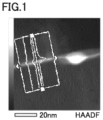
- Fig. 1 shows an exemplary second image.
- a black region corresponds to a region (BN region) including B and N as main constituent elements
- a white region or a gray region corresponds to a region (SF region) recognized as the interface in the first image.
- the SF region in the second image corresponds to the "interface at which the cubic boron nitride grains are adjacent to each other", and the whole of the second image corresponds to the "interface region including the interface ".
- the width of the SF region in a substantially upward/downward direction in Fig. 1
- one different interface is reselected in the first image. This is due to the following reason: when the width of the SF region is more than 10 nm, it is difficult to say that the SF region corresponds to the "interface at which the cubic boron nitride grains are adjacent to each other".
- Fig. 2 is an exemplary graph based on a result of line analysis.
- Fig. 2 shows a result in a solid line with the horizontal axis representing a distance (nm) in which the line analysis is performed and with the vertical axis representing a value of the oxygen content (atom%) at a spot as calculated in accordance with the result of the line analysis.
- the portion at which the peak is observed is the "region in which oxygen exists”
- width D of the peak is "width D of the region in which oxygen exists”.
- width D is more than 10 nm, whereas in the cubic boron nitride sintered material according to the present embodiment, width D is less than or equal to 10 nm. That is, in the cubic boron nitride sintered material according to the present embodiment, the region in which oxygen exists is narrower and has a smaller amount of oxygen than that in the conventional cubic boron nitride sintered material.
- width D becomes 0 nm.
- width D does not fall below 0.1 nm.
- width D of the cubic boron nitride sintered material according to the present embodiment is preferably 0.1 to 5 nm. In this case, the life of the cubic boron nitride sintered material can be longer.
- maximum value M of the content of the oxygen in the region in which the oxygen exists is preferably less than or equal to 5.0 atom%. In this case, the life of the cubic boron nitride sintered material can be longer.
- Maximum value M of the content of the oxygen is the maximum value among the content ratios (atom%) of oxygen at respective spots as calculated in accordance with the result of the line analysis. For example, in Fig. 2 , maximum value M is about 2.4 atom%.
- maximum value M is more than 5.0 atom%
- the amount of oxygen in the cubic boron nitride grains may not be sufficiently reduced.
- the binding strength between the cubic boron nitride grains is not sufficiently high, with the result that the life may be extended insufficiently.
- maximum value M becomes 0 atom%. However, actually, it is difficult to remove oxygen completely.
- the cubic boron nitride sintered material according to the present embodiment has a particularly significantly long life.
- a cutting tool according to the present embodiment includes the above-described cubic boron nitride sintered material.
- the cutting tool includes the cubic boron nitride sintered material as a substrate.
- the cutting tool according to the present embodiment may have a coating film on a part or whole of a surface of the cubic boron nitride sintered material serving as a substrate.
- the shape and application of the cutting tool according to the present embodiment are not particularly limited.
- Examples of the cutting tool according to the present embodiment include a drill, an end mill, an indexable cutting insert for drill, an indexable cutting insert for end mill, an indexable cutting insert for milling, an indexable cutting insert for turning, a metal saw, a gear cutting tool, a reamer, a tap, an insert for crankshaft pin milling, and the like.
- the cutting tool according to the present embodiment is not limited to a cutting tool entirely composed of the cubic boron nitride sintered material, and includes a cutting tool having a portion (particularly, a cutting edge portion or the like) composed of the cubic boron nitride sintered material.
- the cutting tool according to the present embodiment also includes a cutting tool in which a base body (supporting body) composed of a cemented carbide or the like has a cutting edge portion composed of the cubic boron nitride sintered material.
- the cutting edge portion is literally regarded as a cutting tool.
- the cubic boron nitride sintered material is referred to as a cutting tool.
- the cutting tool includes the above-described cubic boron nitride sintered material, and therefore has a long life.
- a method of producing a cubic boron nitride sintered material according to the present embodiment will be described.
- the method of producing the cubic boron nitride sintered material according to the present embodiment is a method of producing the cubic boron nitride sintered material according to the first embodiment.
- the method of producing the cubic boron nitride sintered material at least includes: forming an organic cubic boron nitride powder by removing oxygen of cubic boron nitride source material powder and attaching an organic substance onto the cubic boron nitride source material powder (forming step); preparing a powder mixture including more than or equal to 85 volume% and less than 100 volume% of the organic cubic boron nitride powder and a remainder of a binder source material powder by mixing the organic cubic boron nitride powder and the binder source material powder, the binder source material powder including WC, Co and Al (preparing step); and obtaining the cubic boron nitride sintered material by sintering the powder mixture (sintering step).
- forming step preparing a powder mixture including more than or equal to 85 volume% and less than 100 volume% of the organic cubic boron nitride powder and a remainder of a binder source material powder by mixing the organic cubic boron nitrid
- This step is a step of forming an organic cubic boron nitride powder by removing oxygen of cubic boron nitride source material powder and attaching an organic substance onto the cubic boron nitride source material powder.
- the cubic boron nitride source material powder is a source material powder for the cubic boron nitride grains to be included in the cubic boron nitride sintered material.
- the present inventors have confirmed that oxide exists on the surfaces of the particles of the cubic boron nitride source material powder. This is presumably because the cubic boron nitride source material powder formed through ultra-high pressure synthesis is subjected to a cleaning process and is exposed to an atmospheric air.
- the expression "removing oxygen of the cubic boron nitride source material powder” has the following meanings: an oxide is removed from the cubic boron nitride source material powder; and oxygen atoms are removed.
- Examples of the method of removing the oxygen of the cubic boron nitride source material powder and attaching the organic substance onto the cubic boron nitride source material powder include: a method employing supercritical water; a method of performing plasma treatment; and the like.
- the method employing supercritical water will be described.
- a step of introducing the cubic boron nitride source material powder and the organic substance into supercritical water is performed. Accordingly, the organic cubic boron nitride powder can be formed.
- the supercritical water refers to water in a supercritical state or a subcritical state.
- Examples of the method of introducing the cubic boron nitride source material powder and the organic substance into the supercritical water include: a method of introducing the cubic boron nitride source material powder and the organic substance into the supercritical water in this order; a method of introducing the organic substance and the cubic boron nitride source material powder in this order; and a method of introducing the cubic boron nitride source material powder and the organic substance simultaneously.
- the cubic boron nitride source material powder is brought into contact with the supercritical water, thereby dissolving, in the supercritical water, oxygen on the surfaces of the particles of the cubic boron nitride source material powder. Accordingly, cleaned surfaces are formed with oxygen being removed therefrom. This is because the supercritical water has high solubility. Moreover, the organic substance introduced into the supercritical water is efficiently attached onto the cleaned surfaces of the particles of the organic cubic boron nitride powder. This is due to the following reason: in the supercritical water, the cleaned surfaces are activated to improve the characteristics of attachment to the organic substance.
- a step of attaching the organic substance onto surfaces of particles of the cubic boron nitride source material powder after etching the surfaces of the particles of the cubic boron nitride source material powder by plasma treatment is performed.
- the cubic boron nitride source material powder is exposed to an atmosphere of first gas including carbon and is then exposed to an atmosphere of second gas including ammonia.
- first gas CF 4 , CH 4 , C 2 H 2 or the like can be used.
- the second gas NH 3 , a mixed gas of N 2 and H 2 , or the like can be used.
- the cubic boron nitride source material powder by exposing the cubic boron nitride source material powder to the atmosphere of first gas, the surfaces of the particles of the cubic boron nitride source material powder are etched to remove oxygen therefrom, with the result that the cleaned surfaces are formed and the carbon (first gas) is attached onto the cleaned surfaces. Then, the cubic boron nitride source material powder having the carbon attached thereon is exposed to the atmosphere of second gas, with the result that the carbon is terminated by ammonia. As a result, the organic substance including carbon and nitrogen is attached on the cleaned surfaces.
- the organic cubic boron nitride powder can be efficiently formed by one of the method employing supercritical water and the method of performing plasma treatment. In this step, it is preferable to use the method employing supercritical water. This is due to the following reason: the organic substance to be attached onto the cubic boron nitride source material powder can be readily made uniform and therefore the organic cubic boron nitride powder can be also readily made uniform.
- the average particle size of the cubic boron nitride source material powder is not particularly limited.
- the average particle size of the cubic boron nitride source material powder is preferably 0.1 to 10 ⁇ m, and is more preferably 0.5 to 5.0 ⁇ m.
- the organic substance to be used is preferably an amine or a hydrocarbon compound having a carbon number of more than or equal to 5.
- hexylamine, hexanenitrile, paraffin and hexane are more preferable.
- Hexylamine is further preferable.
- the present inventors have confirmed that when each of these organic substances is used, falling of the cubic boron nitride grains is dramatically reduced in the cubic boron nitride sintered material.
- examples of the organic substance to be attached include an amine, carbon fluoride, and the like.
- a preferable amount of the organic substance to be attached onto the cubic boron nitride source material powder is changed depending on the particle size of the cubic boron nitride source material powder.
- hexylamine is used as the organic substance
- 50 to 2000 ppm of hexylamine is preferably attached onto the cubic boron nitride source material powder having an average particle size of 1 to 10 ⁇ m
- 100 to 5000 ppm of hexylamine is preferably attached onto the cubic boron nitride source material powder having an average particle size of 0.1 to 1 ⁇ m.
- a desired cubic boron nitride sintered material tends to be efficiently produced.
- the amount of the organic substance attached on the organic cubic boron nitride powder can be measured by, for example, gas chromatography mass spectroscopy.
- carbon in the organic cubic boron nitride powder to be subjected to a below-described second step of the sintering step, carbon preferably exists to such an extent that the carbon reacts with remaining oxygen. Further, the amount of the organic substance attached on the cubic boron nitride source material powder tends to be decreased in a subsequent step (for example, a below-described purification step, preparing step, or the like).
- an impurity from the organic cubic boron nitride powder obtained by the above-described forming step, before using the organic cubic boron nitride powder in the below-described preparing step.
- the impurity include an unreacted organic substance. By removing the unreacted organic substance, an unintended reaction in the preparing step and/or sintering step can be suppressed.
- the organic cubic boron nitride powder is obtained as slurry.
- the organic cubic boron nitride powder and the unreacted organic substance can be separated from each other.
- heat treatment may be performed (for example, at more than or equal to 250°C, preferably more than or equal to 400°C, or more preferably more than or equal to 850°C in vacuum) onto the organic cubic boron nitride source material powder removed from the supercritical water or the organic cubic boron nitride source material powder having been subjected to the centrifugal separation or the like after being removed from the supercritical water.
- an impurity such as moisture on the surfaces of the particles of the organic cubic boron nitride powder can be removed.
- the present inventors have initially expected that when the heat treatment is performed onto the organic cubic boron nitride powder, the organic substance attached on the cubic boron nitride source material powder is entirely volatilized and/or ceases to exist. Surprisingly, however, as a result of observing the organic cubic boron nitride powder by Auger electron spectroscopy, it was confirmed that carbon uniformly remains on the surfaces of the particles of the organic cubic boron nitride powder although the organic substance was decomposed due to the heat treatment. This carbon is considered to be originated from the organic substance.
- This step is a step of preparing a powder mixture including more than or equal to 85 volume% and less than 100 volume% of the organic cubic boron nitride powder and a remainder of a binder source material powder by mixing the organic cubic boron nitride powder and the binder source material powder, the binder source material powder including WC, Co and Al.
- the organic cubic boron nitride powder is the organic cubic boron nitride powder obtained by the above-described forming step
- the binder source material powder is a source material for the binder to be included in the cubic boron nitride sintered material.
- the binder source material powder can be prepared as follows. First, WC powder, Co powder, and Al powder are prepared. Next, the powders are mixed at a predetermined ratio and are subjected to heat treatment (for example, 1200°C) in vacuum, thereby forming an intermetallic compound.
- the intermetallic compound is pulverized by a wet ball mill, a wet bead mill, or the like, thereby preparing the binder source material powder including WC, Co, and Al.
- the method of mixing the powders is not particularly limited; however, in order to efficiently and uniformly mix the powders, ball mill mixing, bead mill mixing, planetary mill mixing, jet mill mixing, or the like is preferable. Each of the mixing methods may be performed in a wet manner or dry manner.
- the organic cubic boron nitride powder and the prepared binder source material powder are preferably mixed by wet ball mill mixing employing ethanol, acetone or the like as a solvent. After the mixing, the solvent is removed by natural drying. Then, an impurity such as moisture on the surfaces thereof is preferably removed by heat treatment (for example, at more than or equal to 850°C in vacuum).
- the organic substance is decomposed and the carbon originated from the organic substance can uniformly remain as described above, thereby obtaining the organic cubic boron nitride powder including the particles having the modified surfaces. In this way, the powder mixture is prepared.
- the binder source material powder may include other element(s) in addition to WC, Co, and Al. Suitable examples of the other element(s) include Ni, Fe, Cr, Mn, Ti, V, Zr, Nb, Mo, Hf, Ta, Re, and the like.
- This step is a step of obtaining the cubic boron nitride sintered material by sintering the powder mixture.
- the powder mixture is sintered under a high-temperature and high-pressure condition, thereby producing the cubic boron nitride sintered material.
- a vacuum sealing temperature is preferably more than or equal to 850°C. This temperature is a temperature of more than the melting point of a sealing material, and is a sufficient temperature by which the organic substance attached on the organic cubic boron nitride powder is decomposed and carbon originated from the organic substance remains uniformly on the surfaces of the particles of the organic cubic boron nitride powder.
- the vacuum-sealed powder mixture is sintered using an ultra-high temperature and ultra-high pressure apparatus.
- Sintering conditions are not particularly limited, but are preferably 5.5 to 8 GPa and more than or equal to 1500°C and less than 2000°C. In particular, in view of balance between cost and sintering performance, 6 to 7 GPa and 1600 to 1900°C are preferable.
- the organic cubic boron nitride powder including the particles having the modified surfaces on which carbon remains uniformly is subjected to the first step.
- the organic cubic boron nitride powder including the particles having the modified surfaces is prepared by the first step. Therefore, carbon uniformly exists on the surfaces of the particles of the organic cubic boron nitride powder to be subjected to the second step.
- the carbon attached on the surfaces of the particles of the organic cubic boron nitride powder reacts with the oxygen remaining on the organic cubic boron nitride powder to form carbon monoxide and/or carbon dioxide, which are then discharged to outside of the organic cubic boron nitride powder. Accordingly, oxygen on the organic cubic boron nitride powder is further removed, whereby the powder mixture including the organic cubic boron nitride powder in which the amount of oxygen is sufficiently reduced is sintered. In this way, the cubic boron nitride sintered material was produced.
- a cubic boron nitride sintered material having a long life can be produced. This is due to the following reason.
- the oxygen existing on the cubic boron nitride source material powder is removed and reoxidation is suppressed, thereby forming the organic cubic boron nitride powder in which the amount of oxygen is reduced as compared with the conventional cubic boron nitride source material powder.
- oxygen remaining on the surfaces of the particles of the organic cubic boron nitride powder reacts with carbon remaining on the surfaces of the particles of the organic cubic boron nitride powder to form the reactant, which is then discharged to the outside of the organic cubic boron nitride powder.
- the oxygen remaining on the surfaces of the particles of the cubic boron nitride source material powder is further removed.
- oxygen is removed by an action similar to that in the sintering step. This is because also in the preparing step, a certain amount of heat is applied to the powder mixture.
- the amount of oxygen on the organic cubic boron nitride powder to be subjected to the sintering is significantly reduced as compared with the conventional cubic boron nitride particles. Therefore, neck growth between the cubic boron nitride grains becomes excellent to provide high binding strength between the cubic boron nitride grains, thereby obtaining a cubic boron nitride sintered material having a long life.
- an organic cubic boron nitride powder was formed. Specifically, first, supercritical water was formed using a supercritical water synthesis apparatus ("Momicho mini" provided by ITEC) under the following conditions.
- a hexylamine source solution was continuously introduced into the apparatus to attain a hexylamine concentration of 10.0 weight% in the supercritical water. Further, a cubic boron nitride source material powder having an average particle size of 3 ⁇ m was continuously introduced into the apparatus to attain an amount of the cubic boron nitride source material powder of 10 weight% in the supercritical water. In this way, the cubic boron nitride source material powder and the organic substance were introduced into the supercritical water. After the above-described supercritical water treatment was continued for 100 minutes, the temperature and pressure in the apparatus was returned to normal temperature and pressure to end the supercritical water treatment, and a whole of the obtained slurry was collected.
- the slurry was centrifuged (at 9000 rpm for 8 minutes) to separate an excess of hexylamine not attached on the cubic boron nitride source material powder.
- the concentrated slurry after the separation was dried (at -90°C for 10 hours) to collect about 15 g of powder having been through the supercritical water treatment.
- the organic cubic boron nitride powder was formed.
- the formed organic cubic boron nitride powder was subjected to gas chromatography mass spectroscopy, thus confirming that 782 ppm of hexylamine existed (attached) with respect to the cubic boron nitride powder.
- the obtained powder mixture was sintered to form a cubic boron nitride sintered material.
- the powder mixture was introduced into a container composed of Ta with the powder mixture being in contact with a WC-6%Co cemented carbide disc and a Co foil, and was vacuum-sealed.
- This powder mixture was sintered at 6.5 GPa and 1650°C for 15 minutes using a belt-type ultra-high pressure and ultra-high temperature generating apparatus. In this way, the cubic boron nitride sintered material was formed.
- the concentration of hexylamine to be introduced was set to 5.0 weight%.
- the concentration of hexylamine to be introduced was set to 3.5 weight%.
- the organic cubic boron nitride powder was formed by plasma treatment. Specifically, the surfaces of the particles of the cubic boron nitride source material powder were etched in a CF 4 atmosphere using a plasma modification apparatus (low-pressure plasma apparatus FEMTO provided by Dienner), and then the atmosphere in the apparatus was changed to an NH 3 atmosphere for the purpose of treatment of the cubic boron nitride source material powder having been etched. Except for the above, the cubic boron nitride sintered material was produced in the same manner as in Experiment Example 1.
- a plasma modification apparatus low-pressure plasma apparatus FEMTO provided by Dienner
- a cubic boron nitride sintered material was produced in the same manner as in Experiment Example 2 except that the plasma treatment was performed instead of the method employing supercritical water.
- a cubic boron nitride sintered material was produced in the same manner as in Experiment Example 3 except that the plasma treatment was performed instead of the method employing supercritical water.
- a cubic boron nitride sintered material was produced in the same manner as in Experiment Example 4 except that the plasma treatment was performed instead of the method employing supercritical water.
- a cubic boron nitride sintered material was produced in the same manner as in Experiment Example 5 except that the plasma treatment was used instead of the method employing supercritical water.
- a cubic boron nitride sintered material was produced in the same manner as in Experiment Example 3 except that the powder mixture was prepared using a cubic boron nitride source material powder without the treatment employing supercritical water.
- a cubic boron nitride sintered material was formed in the same manner as in Experiment Example 1 except that the treatment employing supercritical water was not performed and only the cubic boron nitride source material powder was used with no binder source material powder being blended.
- Each of the formed cubic boron nitride sintered materials was cut at an appropriate position, and then its exposed surface was polished to form a smooth surface. Thereafter, an argon ion slicer was used to slice the cubic boron nitride sintered material to form a cut piece having a thickness of 50 nm.
- element mapping analysis and element line analysis by EDX were performed onto a second image (100 nm ⁇ 100 nm) in accordance with the methods described above.
- "JEM-2100F/Cs” (trademark) provided by JEOL was used as a transmission electron microscope.
- EDAX energy dispersive X-ray analyzer
- a beam diameter in the EDX was 0.2 nm and a scanning interval was 0.6 nm.
- Analysis Station provided by JEOL was used as software for the element mapping analysis and element line analysis by EDX. Results thereof are shown in Table 1.
- Fig. 2 shows a graph showing a result of line analysis in experiment example 3.
- each value shown in Table 1 represents an average value in each of the visual fields in each of which the above-described conditions (1) and (2) are satisfied.
- the above-described conditions (1) and (2) were satisfied in all of six arbitrarily extracted interface regions.
- the above-described conditions (1) and (2) were satisfied in one visual field of six arbitrarily extracted interface regions.
- the above-described conditions (1) and (2) were satisfied in three visual fields of six arbitrarily extracted interface regions.
- a specimen having a length of 6 mm, a width of 3 mm, and a thickness of 0.45 to 0.50 mm was cut from each of the formed cubic boron nitride sintered materials, and XRD analysis was performed onto the specimen.
- the acid-treated solution was subjected to ICP analysis.
- the composition of the binder was specified in accordance with the results of XRD analysis and ICP analysis.
- the bending strength (GPa) of each specimen having been through the acid treatment was measured using a three-point bending tester at a stroke speed of 0.5 mm/min with a span of 4 mm. Results thereof are shown in Table 1.
- a cutting tool (substrate shape: DNGA150408; cutting edge treatment: T01225) was formed using each of the formed cubic boron nitride sintered materials. A cutting test was performed using this cutting tool under the following cutting conditions.
- the cutting edge was observed per cutting distance of 0.5 km so as to measure an amount of falling from the cutting edge.
- the amount of falling from the cutting edge was defined as a reduced width from the position of the ridgeline of the cutting edge before the cutting.
- the reduced width results from wear.
- the size of chipping was defined as the amount of falling.
- a cutting distance at a point of time at which the amount of falling from the cutting edge became more than or equal to 0.1 mm was measured. It should be noted that this cutting distance was defined as an index of the life of the cutting tool. Results thereof are shown in Table 1.
- Table 1 also shows the volume% of the cubic boron nitride grains in the cubic boron nitride sintered material. Further, regarding the composition of the binder, it was confirmed that at least WC, Co, and Al compound existed in each of Experiment Examples 1 to 10 and Experiment Examples 21 to 22. Since no distinct peak was detected in XRD with regard to the Al compound, it was presumed that the Al compound was a composite compound composed of a plurality of Al compounds.
Landscapes
- Chemical & Material Sciences (AREA)
- Engineering & Computer Science (AREA)
- Organic Chemistry (AREA)
- Materials Engineering (AREA)
- Ceramic Engineering (AREA)
- Mechanical Engineering (AREA)
- Metallurgy (AREA)
- Manufacturing & Machinery (AREA)
- Structural Engineering (AREA)
- Crystallography & Structural Chemistry (AREA)
- Inorganic Chemistry (AREA)
- Ceramic Products (AREA)
- Cutting Tools, Boring Holders, And Turrets (AREA)
- Powder Metallurgy (AREA)
Claims (4)
- Matériau fritté en nitrure de bore cubique comprenant : 85 % en volume ou plus et moins de 100 % en volume de grains de nitrure de bore cubiques ; et un liant pour le reste, dans lequelle liant inclut WC, Co et un composé d'Al, etquand une TEM-EDX est utilisée pour analyser une région d'interface incluant une interface à laquelle les grains de nitrure de bore cubiques sont adjacents les uns aux autres,de l'oxygène existe sur tout ou partie de l'interface, etla largeur D d'une région dans laquelle de l'oxygène existe est supérieure ou égale à 0,1 nm et inférieure ou égale à 10 nm.
- Matériau fritté en nitrure de bore cubique selon la revendication 1, dans lequel la largeur D est supérieure ou égale à 0,1 nm et inférieure ou égale à 5 nm.
- Matériau fritté en nitrure de bore cubique selon la revendication 1 ou 2, dans lequel la valeur maximale M de la teneur en oxygène dans la région dans laquelle de l'oxygène existe est inférieure ou égale à 5,0 % atomiques.
- Outil de coupe comprenant le matériau fritté en nitrure de bore cubique défini dans l'une quelconque des revendications 1 à 3.
Applications Claiming Priority (2)
| Application Number | Priority Date | Filing Date | Title |
|---|---|---|---|
| JP2018174696 | 2018-09-19 | ||
| PCT/JP2019/036570 WO2020059755A1 (fr) | 2018-09-19 | 2019-09-18 | Corps fritté en nitrure de bore cubique, outil de coupe le contenant, et procédé de production d'un corps fritté en nitrure de bore cubique |
Publications (3)
| Publication Number | Publication Date |
|---|---|
| EP3854898A1 EP3854898A1 (fr) | 2021-07-28 |
| EP3854898A4 EP3854898A4 (fr) | 2022-06-22 |
| EP3854898B1 true EP3854898B1 (fr) | 2024-10-23 |
Family
ID=69887133
Family Applications (1)
| Application Number | Title | Priority Date | Filing Date |
|---|---|---|---|
| EP19862667.3A Active EP3854898B1 (fr) | 2018-09-19 | 2019-09-18 | Corps fritté en nitrure de bore cubique et outil de coupe le contenant |
Country Status (6)
| Country | Link |
|---|---|
| US (1) | US11396482B2 (fr) |
| EP (1) | EP3854898B1 (fr) |
| JP (1) | JP6744519B1 (fr) |
| KR (1) | KR102605373B1 (fr) |
| CN (1) | CN112714801B (fr) |
| WO (1) | WO2020059755A1 (fr) |
Families Citing this family (5)
| Publication number | Priority date | Publication date | Assignee | Title |
|---|---|---|---|---|
| EP4000778B1 (fr) | 2019-07-18 | 2025-02-12 | Sumitomo Electric Industries, Ltd. | Pièce compacte frittée de nitrure de bore cubique et son procédé de fabrication |
| EP4000779B1 (fr) | 2019-07-18 | 2025-04-09 | Sumitomo Electric Industries, Ltd. | Materiau fritté en nitrure de bore cubique |
| US11959156B2 (en) | 2020-07-31 | 2024-04-16 | Sumitomo Electric Industries, Ltd. | Cubic boron nitride sintered material and cutting tool including same |
| EP4242334A4 (fr) * | 2020-11-04 | 2024-01-03 | Sumitomo Electric Industries, Ltd. | Corps fritté en nitrure de bore cubique |
| WO2022163015A1 (fr) * | 2021-01-26 | 2022-08-04 | Jfeスチール株式会社 | Méthode de traitement au plasma, méthode de production de poudre de nitrure de bore hexagonal traitée au plasma, et dispositif de traitement au plasma |
Family Cites Families (18)
| Publication number | Priority date | Publication date | Assignee | Title |
|---|---|---|---|---|
| JPH0621315B2 (ja) | 1986-01-06 | 1994-03-23 | 住友電気工業株式会社 | cBN焼結体およびその製造方法 |
| US5271749A (en) * | 1992-11-03 | 1993-12-21 | Smith International, Inc. | Synthesis of polycrystalline cubic boron nitride |
| EP2224027B1 (fr) | 2004-01-08 | 2016-03-23 | Sumitomo Electric Hardmetal Corp. | Corps fritté en nitrure de bore cubique |
| JP5002886B2 (ja) | 2004-07-09 | 2012-08-15 | 住友電気工業株式会社 | 立方晶窒化ホウ素多結晶体の製造方法 |
| JP2006169080A (ja) | 2004-12-20 | 2006-06-29 | Sumitomo Electric Ind Ltd | 立方晶窒化硼素多結晶体の製造方法 |
| WO2006112156A1 (fr) * | 2005-04-14 | 2006-10-26 | Sumitomo Electric Hardmetal Corp. | OUTIL DE COMPACT FRITTE cBN ET OUTIL DE DECOUPE L'UTILISANT |
| JP2006347850A (ja) * | 2005-06-20 | 2006-12-28 | Sumitomo Electric Ind Ltd | 立方晶窒化硼素焼結体およびその製造方法 |
| WO2007010670A1 (fr) * | 2005-07-15 | 2007-01-25 | Sumitomo Electric Hardmetal Corp. | Compact composite fritté |
| JP4811853B2 (ja) | 2005-09-06 | 2011-11-09 | 独立行政法人物質・材料研究機構 | 高純度立方晶窒化ホウ素焼結体の製造法 |
| CA2571470C (fr) * | 2005-11-18 | 2013-02-05 | Sumitomo Electric Hardmetal Corp. | Corps fritte au cbn pour usinage a haute integrite de surface, outil de coupe avec corps fritte au cbn, et methode de coupe applicable |
| US9346716B2 (en) * | 2010-03-12 | 2016-05-24 | Sumitomo Electric Hardmetal Corp. | Tool made of cubic boron nitride sintered body |
| EP2835195B1 (fr) * | 2012-04-03 | 2020-11-18 | Sumitomo Electric Hardmetal Corp. | Outil en nitrure de bore cubique fritté |
| US20130291446A1 (en) * | 2012-05-02 | 2013-11-07 | Sumitomo Electric Hardmetal Corp. | Tool made of cubic boron nitride sintered body |
| JP6650106B2 (ja) * | 2014-11-27 | 2020-02-19 | 三菱マテリアル株式会社 | 立方晶窒化ほう素基焼結体および立方晶窒化ほう素基焼結体製切削工具 |
| WO2016084929A1 (fr) * | 2014-11-27 | 2016-06-02 | 三菱マテリアル株式会社 | Objet fritté à base de nitrure de bore cubique et outil coupant constitué d'un objet fritté à base de nitrure de bore cubique |
| WO2018101346A1 (fr) * | 2016-11-30 | 2018-06-07 | 住友電気工業株式会社 | Diamant polycristallin ainsi que procédé de fabrication de celui-ci, outil de rainurage, roue de rainurage, dresseur, outil rotatif, filière à étirer, outil de coupe, électrode, et procédé d'usinage mettant en œuvre un diamant polycristallin |
| KR102634862B1 (ko) * | 2017-01-13 | 2024-02-06 | 에스케이케미칼 주식회사 | 합성 목재 |
| US10355615B2 (en) | 2017-03-30 | 2019-07-16 | Lapis Semiconductor Co., Ltd. | Rectifier circuit for opposite-phase currents |
-
2019
- 2019-09-18 EP EP19862667.3A patent/EP3854898B1/fr active Active
- 2019-09-18 JP JP2020506825A patent/JP6744519B1/ja active Active
- 2019-09-18 WO PCT/JP2019/036570 patent/WO2020059755A1/fr not_active Ceased
- 2019-09-18 KR KR1020217011398A patent/KR102605373B1/ko active Active
- 2019-09-18 US US17/262,215 patent/US11396482B2/en active Active
- 2019-09-18 CN CN201980061297.3A patent/CN112714801B/zh active Active
Also Published As
| Publication number | Publication date |
|---|---|
| EP3854898A1 (fr) | 2021-07-28 |
| US20210246078A1 (en) | 2021-08-12 |
| JPWO2020059755A1 (ja) | 2021-01-07 |
| KR20210060569A (ko) | 2021-05-26 |
| CN112714801A (zh) | 2021-04-27 |
| US11396482B2 (en) | 2022-07-26 |
| WO2020059755A1 (fr) | 2020-03-26 |
| KR102605373B1 (ko) | 2023-11-23 |
| JP6744519B1 (ja) | 2020-08-19 |
| CN112714801B (zh) | 2022-08-12 |
| EP3854898A4 (fr) | 2022-06-22 |
Similar Documents
| Publication | Publication Date | Title |
|---|---|---|
| EP3854898B1 (fr) | Corps fritté en nitrure de bore cubique et outil de coupe le contenant | |
| EP3854899B1 (fr) | Corps fritté en nitrure de bore cubique et outil de coupe contenant celui-ci | |
| US12054813B2 (en) | Method of producing cubic boron nitride sintered material, cubic boron nitride sintered material, and cutting tool including cubic boron nitride sintered material | |
| EP4000778B1 (fr) | Pièce compacte frittée de nitrure de bore cubique et son procédé de fabrication | |
| KR20230043853A (ko) | 입방정 질화붕소 소결체 및 그것을 포함하는 절삭 공구 | |
| EP4000779B1 (fr) | Materiau fritté en nitrure de bore cubique | |
| EP4001241B1 (fr) | Corps fritté en nitrure de bore cubique | |
| EP4001242B1 (fr) | Corps fritté en nitrure de bore cubique | |
| EP4190469A1 (fr) | Compact fritté en nitrure de bore cubique, et outil de coupe le contenant | |
| EP4000777B1 (fr) | Corps fritté en nitrure de bore cubique, et outil de coupe |
Legal Events
| Date | Code | Title | Description |
|---|---|---|---|
| STAA | Information on the status of an ep patent application or granted ep patent |
Free format text: STATUS: THE INTERNATIONAL PUBLICATION HAS BEEN MADE |
|
| PUAI | Public reference made under article 153(3) epc to a published international application that has entered the european phase |
Free format text: ORIGINAL CODE: 0009012 |
|
| STAA | Information on the status of an ep patent application or granted ep patent |
Free format text: STATUS: REQUEST FOR EXAMINATION WAS MADE |
|
| 17P | Request for examination filed |
Effective date: 20210217 |
|
| AK | Designated contracting states |
Kind code of ref document: A1 Designated state(s): AL AT BE BG CH CY CZ DE DK EE ES FI FR GB GR HR HU IE IS IT LI LT LU LV MC MK MT NL NO PL PT RO RS SE SI SK SM TR |
|
| DAV | Request for validation of the european patent (deleted) | ||
| DAX | Request for extension of the european patent (deleted) | ||
| A4 | Supplementary search report drawn up and despatched |
Effective date: 20220523 |
|
| RIC1 | Information provided on ipc code assigned before grant |
Ipc: C22C 29/02 20060101ALI20220517BHEP Ipc: C22C 26/00 20060101ALI20220517BHEP Ipc: C04B 35/645 20060101ALI20220517BHEP Ipc: B22F 5/00 20060101ALI20220517BHEP Ipc: C22C 1/05 20060101ALI20220517BHEP Ipc: C04B 35/5831 20060101ALI20220517BHEP Ipc: B23B 27/14 20060101ALI20220517BHEP Ipc: C22C 29/16 20060101AFI20220517BHEP |
|
| GRAP | Despatch of communication of intention to grant a patent |
Free format text: ORIGINAL CODE: EPIDOSNIGR1 |
|
| STAA | Information on the status of an ep patent application or granted ep patent |
Free format text: STATUS: GRANT OF PATENT IS INTENDED |
|
| INTG | Intention to grant announced |
Effective date: 20240528 |
|
| GRAS | Grant fee paid |
Free format text: ORIGINAL CODE: EPIDOSNIGR3 |
|
| GRAA | (expected) grant |
Free format text: ORIGINAL CODE: 0009210 |
|
| STAA | Information on the status of an ep patent application or granted ep patent |
Free format text: STATUS: THE PATENT HAS BEEN GRANTED |
|
| P01 | Opt-out of the competence of the unified patent court (upc) registered |
Free format text: CASE NUMBER: APP_50723/2024 Effective date: 20240906 |
|
| AK | Designated contracting states |
Kind code of ref document: B1 Designated state(s): AL AT BE BG CH CY CZ DE DK EE ES FI FR GB GR HR HU IE IS IT LI LT LU LV MC MK MT NL NO PL PT RO RS SE SI SK SM TR |
|
| REG | Reference to a national code |
Ref country code: GB Ref legal event code: FG4D |
|
| REG | Reference to a national code |
Ref country code: CH Ref legal event code: EP |
|
| REG | Reference to a national code |
Ref country code: DE Ref legal event code: R096 Ref document number: 602019060908 Country of ref document: DE |
|
| REG | Reference to a national code |
Ref country code: IE Ref legal event code: FG4D |
|
| REG | Reference to a national code |
Ref country code: SE Ref legal event code: TRGR |
|
| REG | Reference to a national code |
Ref country code: LT Ref legal event code: MG9D |
|
| REG | Reference to a national code |
Ref country code: NL Ref legal event code: MP Effective date: 20241023 |
|
| REG | Reference to a national code |
Ref country code: AT Ref legal event code: MK05 Ref document number: 1734887 Country of ref document: AT Kind code of ref document: T Effective date: 20241023 |
|
| PG25 | Lapsed in a contracting state [announced via postgrant information from national office to epo] |
Ref country code: NL Free format text: LAPSE BECAUSE OF FAILURE TO SUBMIT A TRANSLATION OF THE DESCRIPTION OR TO PAY THE FEE WITHIN THE PRESCRIBED TIME-LIMIT Effective date: 20241023 |
|
| PG25 | Lapsed in a contracting state [announced via postgrant information from national office to epo] |
Ref country code: NL Free format text: LAPSE BECAUSE OF FAILURE TO SUBMIT A TRANSLATION OF THE DESCRIPTION OR TO PAY THE FEE WITHIN THE PRESCRIBED TIME-LIMIT Effective date: 20241023 |
|
| PG25 | Lapsed in a contracting state [announced via postgrant information from national office to epo] |
Ref country code: PT Free format text: LAPSE BECAUSE OF FAILURE TO SUBMIT A TRANSLATION OF THE DESCRIPTION OR TO PAY THE FEE WITHIN THE PRESCRIBED TIME-LIMIT Effective date: 20250224 Ref country code: IS Free format text: LAPSE BECAUSE OF FAILURE TO SUBMIT A TRANSLATION OF THE DESCRIPTION OR TO PAY THE FEE WITHIN THE PRESCRIBED TIME-LIMIT Effective date: 20250223 Ref country code: HR Free format text: LAPSE BECAUSE OF FAILURE TO SUBMIT A TRANSLATION OF THE DESCRIPTION OR TO PAY THE FEE WITHIN THE PRESCRIBED TIME-LIMIT Effective date: 20241023 |
|
| PG25 | Lapsed in a contracting state [announced via postgrant information from national office to epo] |
Ref country code: FI Free format text: LAPSE BECAUSE OF FAILURE TO SUBMIT A TRANSLATION OF THE DESCRIPTION OR TO PAY THE FEE WITHIN THE PRESCRIBED TIME-LIMIT Effective date: 20241023 |
|
| PG25 | Lapsed in a contracting state [announced via postgrant information from national office to epo] |
Ref country code: BG Free format text: LAPSE BECAUSE OF FAILURE TO SUBMIT A TRANSLATION OF THE DESCRIPTION OR TO PAY THE FEE WITHIN THE PRESCRIBED TIME-LIMIT Effective date: 20241023 |
|
| PG25 | Lapsed in a contracting state [announced via postgrant information from national office to epo] |
Ref country code: ES Free format text: LAPSE BECAUSE OF FAILURE TO SUBMIT A TRANSLATION OF THE DESCRIPTION OR TO PAY THE FEE WITHIN THE PRESCRIBED TIME-LIMIT Effective date: 20241023 |
|
| PG25 | Lapsed in a contracting state [announced via postgrant information from national office to epo] |
Ref country code: NO Free format text: LAPSE BECAUSE OF FAILURE TO SUBMIT A TRANSLATION OF THE DESCRIPTION OR TO PAY THE FEE WITHIN THE PRESCRIBED TIME-LIMIT Effective date: 20250123 |
|
| PG25 | Lapsed in a contracting state [announced via postgrant information from national office to epo] |
Ref country code: AT Free format text: LAPSE BECAUSE OF FAILURE TO SUBMIT A TRANSLATION OF THE DESCRIPTION OR TO PAY THE FEE WITHIN THE PRESCRIBED TIME-LIMIT Effective date: 20241023 Ref country code: LV Free format text: LAPSE BECAUSE OF FAILURE TO SUBMIT A TRANSLATION OF THE DESCRIPTION OR TO PAY THE FEE WITHIN THE PRESCRIBED TIME-LIMIT Effective date: 20241023 Ref country code: GR Free format text: LAPSE BECAUSE OF FAILURE TO SUBMIT A TRANSLATION OF THE DESCRIPTION OR TO PAY THE FEE WITHIN THE PRESCRIBED TIME-LIMIT Effective date: 20250124 |
|
| PG25 | Lapsed in a contracting state [announced via postgrant information from national office to epo] |
Ref country code: PL Free format text: LAPSE BECAUSE OF FAILURE TO SUBMIT A TRANSLATION OF THE DESCRIPTION OR TO PAY THE FEE WITHIN THE PRESCRIBED TIME-LIMIT Effective date: 20241023 |
|
| PG25 | Lapsed in a contracting state [announced via postgrant information from national office to epo] |
Ref country code: RS Free format text: LAPSE BECAUSE OF FAILURE TO SUBMIT A TRANSLATION OF THE DESCRIPTION OR TO PAY THE FEE WITHIN THE PRESCRIBED TIME-LIMIT Effective date: 20250123 |
|
| PG25 | Lapsed in a contracting state [announced via postgrant information from national office to epo] |
Ref country code: SM Free format text: LAPSE BECAUSE OF FAILURE TO SUBMIT A TRANSLATION OF THE DESCRIPTION OR TO PAY THE FEE WITHIN THE PRESCRIBED TIME-LIMIT Effective date: 20241023 |
|
| PG25 | Lapsed in a contracting state [announced via postgrant information from national office to epo] |
Ref country code: DK Free format text: LAPSE BECAUSE OF FAILURE TO SUBMIT A TRANSLATION OF THE DESCRIPTION OR TO PAY THE FEE WITHIN THE PRESCRIBED TIME-LIMIT Effective date: 20241023 |
|
| PG25 | Lapsed in a contracting state [announced via postgrant information from national office to epo] |
Ref country code: EE Free format text: LAPSE BECAUSE OF FAILURE TO SUBMIT A TRANSLATION OF THE DESCRIPTION OR TO PAY THE FEE WITHIN THE PRESCRIBED TIME-LIMIT Effective date: 20241023 |
|
| PG25 | Lapsed in a contracting state [announced via postgrant information from national office to epo] |
Ref country code: RO Free format text: LAPSE BECAUSE OF FAILURE TO SUBMIT A TRANSLATION OF THE DESCRIPTION OR TO PAY THE FEE WITHIN THE PRESCRIBED TIME-LIMIT Effective date: 20241023 |
|
| REG | Reference to a national code |
Ref country code: DE Ref legal event code: R097 Ref document number: 602019060908 Country of ref document: DE |
|
| PG25 | Lapsed in a contracting state [announced via postgrant information from national office to epo] |
Ref country code: SK Free format text: LAPSE BECAUSE OF FAILURE TO SUBMIT A TRANSLATION OF THE DESCRIPTION OR TO PAY THE FEE WITHIN THE PRESCRIBED TIME-LIMIT Effective date: 20241023 |
|
| PG25 | Lapsed in a contracting state [announced via postgrant information from national office to epo] |
Ref country code: CZ Free format text: LAPSE BECAUSE OF FAILURE TO SUBMIT A TRANSLATION OF THE DESCRIPTION OR TO PAY THE FEE WITHIN THE PRESCRIBED TIME-LIMIT Effective date: 20241023 |
|
| PG25 | Lapsed in a contracting state [announced via postgrant information from national office to epo] |
Ref country code: IT Free format text: LAPSE BECAUSE OF FAILURE TO SUBMIT A TRANSLATION OF THE DESCRIPTION OR TO PAY THE FEE WITHIN THE PRESCRIBED TIME-LIMIT Effective date: 20241023 |
|
| PLBE | No opposition filed within time limit |
Free format text: ORIGINAL CODE: 0009261 |
|
| STAA | Information on the status of an ep patent application or granted ep patent |
Free format text: STATUS: NO OPPOSITION FILED WITHIN TIME LIMIT |
|
| 26N | No opposition filed |
Effective date: 20250724 |
|
| PGFP | Annual fee paid to national office [announced via postgrant information from national office to epo] |
Ref country code: DE Payment date: 20250730 Year of fee payment: 7 |
|
| PGFP | Annual fee paid to national office [announced via postgrant information from national office to epo] |
Ref country code: SE Payment date: 20250728 Year of fee payment: 7 |
|
| PGFP | Annual fee paid to national office [announced via postgrant information from national office to epo] |
Ref country code: IE Payment date: 20250812 Year of fee payment: 7 |