EP3854929A1 - Appareil électroménager à circulation d'eau pourvu de réservoir pour un produit de traitement - Google Patents
Appareil électroménager à circulation d'eau pourvu de réservoir pour un produit de traitement Download PDFInfo
- Publication number
- EP3854929A1 EP3854929A1 EP20216866.2A EP20216866A EP3854929A1 EP 3854929 A1 EP3854929 A1 EP 3854929A1 EP 20216866 A EP20216866 A EP 20216866A EP 3854929 A1 EP3854929 A1 EP 3854929A1
- Authority
- EP
- European Patent Office
- Prior art keywords
- valve
- valve closing
- closing body
- water
- actuating
- Prior art date
- Legal status (The legal status is an assumption and is not a legal conclusion. Google has not performed a legal analysis and makes no representation as to the accuracy of the status listed.)
- Granted
Links
Images


Classifications
-
- D—TEXTILES; PAPER
- D06—TREATMENT OF TEXTILES OR THE LIKE; LAUNDERING; FLEXIBLE MATERIALS NOT OTHERWISE PROVIDED FOR
- D06F—LAUNDERING, DRYING, IRONING, PRESSING OR FOLDING TEXTILE ARTICLES
- D06F39/00—Details of washing machines not specific to a single type of machines covered by groups D06F9/00 - D06F27/00
- D06F39/02—Devices for adding soap or other washing agents
- D06F39/022—Devices for adding soap or other washing agents in a liquid state
-
- A—HUMAN NECESSITIES
- A47—FURNITURE; DOMESTIC ARTICLES OR APPLIANCES; COFFEE MILLS; SPICE MILLS; SUCTION CLEANERS IN GENERAL
- A47L—DOMESTIC WASHING OR CLEANING; SUCTION CLEANERS IN GENERAL
- A47L15/00—Washing or rinsing machines for crockery or tableware
- A47L15/42—Details
- A47L15/44—Devices for adding cleaning agents; Devices for dispensing cleaning agents, rinsing aids or deodorants
- A47L15/4418—Devices for adding cleaning agents; Devices for dispensing cleaning agents, rinsing aids or deodorants in the form of liquids
-
- A—HUMAN NECESSITIES
- A47—FURNITURE; DOMESTIC ARTICLES OR APPLIANCES; COFFEE MILLS; SPICE MILLS; SUCTION CLEANERS IN GENERAL
- A47L—DOMESTIC WASHING OR CLEANING; SUCTION CLEANERS IN GENERAL
- A47L15/00—Washing or rinsing machines for crockery or tableware
- A47L15/42—Details
- A47L15/44—Devices for adding cleaning agents; Devices for dispensing cleaning agents, rinsing aids or deodorants
- A47L15/4463—Multi-dose dispensing arrangements
-
- A—HUMAN NECESSITIES
- A47—FURNITURE; DOMESTIC ARTICLES OR APPLIANCES; COFFEE MILLS; SPICE MILLS; SUCTION CLEANERS IN GENERAL
- A47L—DOMESTIC WASHING OR CLEANING; SUCTION CLEANERS IN GENERAL
- A47L15/00—Washing or rinsing machines for crockery or tableware
- A47L15/42—Details
- A47L15/44—Devices for adding cleaning agents; Devices for dispensing cleaning agents, rinsing aids or deodorants
- A47L15/449—Metering controlling devices
-
- G—PHYSICS
- G01—MEASURING; TESTING
- G01F—MEASURING VOLUME, VOLUME FLOW, MASS FLOW OR LIQUID LEVEL; METERING BY VOLUME
- G01F11/00—Apparatus requiring external operation adapted at each repeated and identical operation to measure and separate a predetermined volume of fluid or fluent solid material from a supply or container, without regard to weight, and to deliver it
- G01F11/28—Apparatus requiring external operation adapted at each repeated and identical operation to measure and separate a predetermined volume of fluid or fluent solid material from a supply or container, without regard to weight, and to deliver it with stationary measuring chambers having constant volume during measurement
Definitions
- the invention relates to a water-bearing household appliance, in particular a laundry treatment device for washing and / or drying laundry, with a storage container for a treatment agent and a valve via which the treatment agent can be guided from the storage container into a treatment area.
- the invention relates to the field of washing machines and washer-dryers.
- a water-bearing domestic appliance with a housing, a stationary container which is arranged in a stationary manner in the housing, and a removable container is known.
- the removable container is connected to the stationary container in an inserted state in which the removable container is inserted into the housing.
- the stationary container can serve as a reserve container and the removable container as a storage container.
- the removable container has a ball cage at an outlet point in which a ball is arranged.
- the ball cage has a lower opening and a side opening in the form of a window.
- a close guide in the ball cage is required for the ball in order to ensure the seal.
- large adjustment movements of the ball are also required in order to enable a sufficient flow cross-section for the generally comparatively viscous laundry treatment agent to flow out. If the ball sticks in its upper position, in which the laundry treatment agent can flow out, a longer flow can also result when the partially filled container is removed. This can lead to soiling in the housing and unnecessary consumption of the laundry treatment agent.
- One object of the invention is to create a water-bearing household appliance which has an improved structure.
- a water-bearing household appliance which serves in particular as a laundry treatment device for washing and / or drying laundry
- the water-bearing household appliance having a treatment area, a storage container which is designed to hold a quantity of a treatment agent that is sufficient for several treatment processes, and has a valve via which the treatment agent can be guided at least indirectly from the storage container into the treatment area
- the valve having a valve seat body which is at least partially plate-shaped is designed, and has a, in particular annular, valve closing body, wherein the valve closing body is acted upon by at least a closing force against the valve seat body and wherein a sealing seat is formed between the valve seat body and the valve closing body.
- the valve in which the at least partially plate-shaped valve seat body interacts with the preferably ring-shaped valve closing body to form the sealing seat, enables a large opening cross-section when the sealing seat is opened. In this case, even with a comparatively small stroke, a sufficiently large opening cross-section can be achieved in order to also allow comparatively viscous treatment agents to flow through at a sufficient flow rate. Furthermore, the valve enables both a connection of the storage container and a metering, which takes place by opening the sealing seat and then closing the sealing seat. In this way, an additional metering device, in particular a metering pump, can be saved.
- an actuating body which, in order to open the sealing seat formed between the valve seat body and the valve closing body, actuates the valve closing body against the closing force, and that the actuating body has an opening through which the treatment agent from the storage container at least indirectly when the sealing seat is open flows to the treatment area.
- the actuating body is designed as an at least essentially tubular actuating body.
- a seal is formed between the actuating body and the valve closing body along a closed curve which surrounds the opening of the actuating body when the actuating body is the valve closing body operated against the closing force.
- a seal can thus be formed between the preferably tubular actuating body and the valve closing body, in particular, precisely when the treatment agent flows over the open sealing seat.
- a certain, slight pre-tension is exerted on the actuating body in order to ensure the seal between the actuating body and the valve closing body even between the individual metering processes.
- the actuating body has an interior which is designed as a portion chamber, and that the actuating body receives the treatment agent in a portion amount when the interior of the actuating body is filled with the treatment agent, which is at least essentially determined by the volume of the portion chamber .
- the desired dosage amount can then be guided into the treatment area by means of the number of portion amounts withdrawn during a dosage process.
- actuating bodies with portion chambers of different sizes can also be provided, which remove treatment agent from the storage container via a corresponding number of valves. This enables quick and precise removal of the desired dosage from the storage container.
- a control and an actuating device are provided that the actuating device adjusts the actuating body to open the sealing seat formed between the valve seat body and the valve closing body and that the control is set up to control the actuating device in accordance with a program sequence in such a way that at least one Dosing process in which the sealing seat is opened and then closed, at least approximately a dosing amount of the treatment agent determined according to the program sequence is fed into the treatment area.
- the dosing amount can be determined via the opening time between the opening and the subsequent closing of the sealing seat and / or via the number of dosing processes in which the sealing seat is opened and then closed.
- a constant or a variable opening duration can thus be specified for a single dosing process.
- the dosage can also be combined with respect to a suitable detection of a treatment agent concentration in the treatment area, which is possible, for example, by one or more sensors that are arranged in the treatment area or at another suitable location in the water-carrying household appliance.
- a closing spring is advantageously provided which applies the closing force to the valve closing body against the valve seat body, the closing spring being arranged between an outer collar of the valve closing body and the storage container. Furthermore, it is advantageous that an elastically deformable connecting piece is provided, via which the valve closing body is connected to the storage container.
- the closing spring can be provided outside the elastically deformable connecting piece.
- the closing spring can enclose the elastically deformable connecting piece with several turns.
- the closing spring can, however, also be configured and suitably arranged in a different manner.
- the elastically deformable connecting piece can advantageously be designed as a bellows or as an elastic tube piece. In order to enable a stroke of the valve closing body, suitable deformations can result on the elastic tube piece.
- the elastic tube piece can be designed as a flexible, tube-like tube piece, with the axial movement required for the valve closing body and also other movement components being able to be obtained from a bow or a loop.
- valve seat body has a plate-shaped part and a guide part, that the sealing seat is formed between the plate-shaped part of the valve seat body and the valve closing body, and that the valve closing body is in a predetermined position relative to when the sealing seat is closed by the guide part of the valve seat body the plate-shaped part of the valve seat body is guided.
- a suitable guide can be implemented in order to achieve reliable closing of the sealing seat.
- the guide part of the valve seat body is designed such that the valve closing body actuated by the actuating body can be tilted relative to the valve seat body.
- valve closing body It is also advantageous that a flat sealing surface is formed on the valve closing body and that the valve closing body rests with its sealing surface on an annular sealing element provided on the valve seat body when the sealing seat is closed. As a result, the positioning of the valve closing body relative to the valve seat body can also be supported in addition to the guidance by the guide part of the valve seat body.
- a sealing surface in the form of part of a spherical surface is formed on the valve closing body and that the valve closing body rests with its sealing surface on an annular sealing element provided on the valve seat body when the sealing seat is closed.
- the guide part can also be guided with greater play, or such a guide can also be omitted. Because the sealing surface in the form of the part of the spherical surface can ensure a reliable seal in different positions of the valve closing body relative to the valve seat body. This also has an advantageous effect on repeated actuation. Furthermore, this facilitates any sealing that may be provided between the actuating body and the valve closing body, which is provided during actuation and possibly also when the sealing seat is closed.
- the sealing seat between the valve seat body and the valve closing body is preferably opened and then closed again.
- the fluid flow is switched on and off completely.
- the fluid flow it is also possible for the fluid flow to be continuously controlled, in that it is continuously controlled, in particular regulated, via the generated opening stroke of the valve closing body or the resulting flow cross-section via which the treatment agent is guided out of the storage container via the valve.
- the concentration of an aqueous solution of the treatment agent fed into the treatment area can be measured via a sensor and the fluid flow is regulated accordingly.
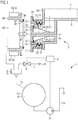
- Fig. 1 shows a water-carrying household appliance 1 in a partial, schematic sectional view corresponding to a first embodiment.
- the water-bearing household appliance 1 has a valve 2, which is shown in a closed valve state.
- the water-carrying household appliance 1 also has a storage container 3 which holds a treatment agent 4.
- the storage container 3 is designed to hold an amount of the treatment agent 4 that is sufficient for several treatments or for several program runs.
- several chambers can be provided in the storage container 3 for receiving serve several, possibly different treatment agents. Accordingly, further valves can then also be provided which correspond to valve 2.
- the treatment agent 4 can be fed into a chamber 5 of a flushing device 6 via the valve 2.
- a fresh water line 7, in which a shut-off valve 8 is arranged, also opens into the chamber 5.
- a controller 9 is used to control the shut-off valve 8 in order to feed fresh water from a water connection 10 via the fresh water line 7 into the flushing device 6 in accordance with a program sequence.
- With the valve 2 closed fresh water can thus be fed into a treatment area 12 within a treatment tank 13 via an inlet connection 11.
- the inlet connector 11 connects the flushing device 6 to the treatment container 13.
- the treatment container 13 can in particular be designed as a tub 13.
- a pump 14 that can be controlled by the controller 9 is provided, which can in particular be configured as a drain pump 14.
- the pump 14 can pump the liquid out of the treatment area 12 via a pumping line 15.
- further functions can also be implemented, in particular an optional pump-around function in which the liquid can either be pumped out of the treatment area 12 or returned to the treatment area 12, depending on the program sequence.
- laundry in particular can be subjected to laundry treatment with one or more treatment agents 4.
- One or more treatment agents can be used here. At least one of these treatment agents is stored as treatment agent 4 in the storage container 3. Automatic dosing of the treatment agent 4 is possible in accordance with the program sequence of the controller 9.
- manual dosing of a further treatment agent by a user can optionally also be enabled.
- the user can, for example, introduce such a further treatment agent into a chamber of the induction device 6 before starting the program sequence, which can be the chamber 5 or also another chamber of the induction device 6.
- the storage container 3 is preferably designed as a removable storage container 3.
- the storage container 3 can be removed from a housing of the water-bearing household appliance 1 in order to fill the storage container 3. This makes handling much easier for a user.
- the storage container 3 can be designed as a pull-out storage container 3, which can optionally be wholly or partially pulled out of the housing. This means that it can be filled in when it is partially pulled out. In the completely removed state, the storage container 3 can then be cleaned by the user in a simple manner, in particular by showering.
- a receptacle for the storage container 3 in the water-carrying household appliance 1 is hereby accessible in order to enable such a receptacle to be cleaned.
- the valve 2 is designed on the storage container 3 and is at least partially an integral part of the storage container 3.
- the valve 2 has a valve seat body 20 which is designed in one piece with the storage container 3.
- the valve seat body 20 and the storage container 3 can be produced as a common injection-molded part from a plastic.
- the valve seat body 20 can also be injection molded onto the storage container 3.
- the valve seat body 20 has a plate-shaped part 21, a connecting part 22 and a guide part 23.
- the valve seat body is partially designed in the shape of a plate.
- the plate-shaped part 21 is connected to the storage container 3 via the connecting part 22.
- the connecting part 22 extends along an axis 24 of the valve 2.
- the elastically deformable connecting piece 30 is designed as a bellows 30 in this exemplary embodiment.
- the elastically deformable connecting piece 30 can also be designed as an elastic tube piece 30.
- the valve closing body has a flat sealing surface 31. Furthermore, an annular sealing element 32 is provided on the valve seat body 20 which faces the flat sealing surface 31 of the valve closing body 25. In the closed position, the valve closing body 25 rests with its sealing surface 31 on the annular sealing element 32, which is provided on the valve seat body 20. As a result, the sealing seat between the valve closing body 25 and the valve seat body 20 is closed.
- the water-carrying household appliance 1 has an actuating device 33 which comprises actuators 34, 35. Furthermore, an actuating body 36 is provided, which is designed as a tubular actuating body 36. The actuating body 36 has an opening 38 at an end facing the valve 2. Furthermore, a sealing ring 39 is attached to the end 37. The sealing ring 39 of the actuating body 36 faces an outer side 40 of the valve closing body 25.
- the actuators 34, 35 of the actuating device 33 actuate the actuating body 36 so that the actuating body 36 is adjusted in a direction 41.
- the direction 41 is here preferably oriented along the axis 24.
- the tubular actuating body 36 is preferably aligned with respect to the axis 24.
- the actuating body 36 with its sealing ring 39 comes into contact with the outside 40 of the valve closing body 25. Then the valve 2 opens or the sealing seat, which is formed between the valve seat body 20 and the valve closing body 25, opens.
- Fig. 2 shows a partial representation of the in Fig. 1 shown water-bearing
- Household appliance 1 of the first embodiment in an open valve state the actuating body 36 has actuated the valve closing body 25 in the axial direction.
- the valve 2 is opened by axially displacing the valve closing body 25 against the closing force of the closing spring 27. This opens the sealing seat and creates an annular gap 42 between the valve closing body 25 and the plate-shaped part 21 of the valve seat body 20
- the treatment agent 4, which is initially still closed, can flow into an interior 43 of the tubular actuating body 36 in the open valve state via the annular gap 42.
- the tubular actuating body 36 which actuates the valve closing body 25, also serves as a pipeline for the forwarding of the treatment agent 4 36 encloses, formed when the actuating body 36 actuates the valve closing body 25 against the closing force of the closing spring 27. This prevents the treatment agent 4 from escaping in the area of the valve 2 when the valve 2 is open.
- the seal is formed on the sealing seat between the valve closing body 25 and the valve seat body 20. The treatment agent 4 is thus either held in the storage container 3 or passed through the tubular actuating body 36.
- the actuating body 36 is designed as an actuating tappet 36.
- the actuating device 33 actuating the valve 2 with the actuators 34, 35 can be designed simply and inexpensively. This is achieved, among other things, in that essentially all sealing and guiding functions are designed in an axial design. This means that comparatively low axial forces occur when the valve 2 is opened and closed. In particular, this results in low frictional forces and comparatively low forces are required to generate the respective sealing effect due to the essentially axial compression of the sealing element 32 or the sealing ring 39. Furthermore, due to the compact design of the valve 2 with comparatively small dimensions, a large flow cross-section or line cross-section can be provided, which is available in the open valve state for the passage of the treatment agent 4. As a result, large volume flows can be achieved even with treatment agents 4 with a higher viscosity.
- Fig. 3 shows a partial representation of the in Fig. 1 shown water-conducting household appliance of the first embodiment in a further possible position of the valve 2 in the open valve state.
- the valve closing body 25 is opposite that in the Fig. 2 tilted axially aligned position shown.
- the actuating body 36 with its sealing ring 39 rests eccentrically on the outside 40 of the valve closing body 25. Tolerance compensation is thus also made possible in this regard.
- the actuating body 36 and the valve closing body 25, which work together when the valve 2 is actuated can be displaced and / or pivoted relative to one another over a large area, so that there is a high tolerance with regard to the required accuracy in manufacture, assembly and operation .
- This also results in an improved tolerance for inserting the storage container 3 into a suitable receptacle in the housing of the water-bearing household appliance 1 if the storage container 3 is designed as a removable and / or pull-out storage container 3.
- the valve-closing body 25 When the valve 2 is closed, the valve-closing body 25 is moved by the guide part 23 back into the position shown in FIG Fig. 1 The starting position shown is guided in the closed valve state. The movement is guaranteed by the closing force of the closing spring 27.
- the guide part 23 is formed by guide ribs 50, 51, which are designed as centering ribs 50, 51 and serve to center the movable valve-closing body 25.
- the number of such guide ribs 50, 51 can be predetermined in relation to the respective application.
- a certain thrust force or actuation force is required, which must be applied by the actuators 34, 35 of the actuation device 33.
- This thrust force for opening the valve 2 is essentially due to the closing force of the closing spring 27 plus the force required to deform the elastically deformable connecting piece 30 with the column of liquid acting on it of the treatment agent 4 given.
- the valve closing body 25 is acted upon by at least the closing force of the closing spring 27 against the valve seat body 20.
- the actuating body 36 can also be configured in a different way.
- the actuating body 36 can have an interior 43 which is designed as a portion chamber 43.
- the interior 43 can then be filled with treatment agent 4 by temporarily opening the valve 2.
- the portion chamber 43 is filled until the same filling level is reached in the interior 43 as in the storage container 3 in the interior of the actuating body 36 according to the principle of mutually communicating tubes.
- the interior 43 of the actuating body is designed in such a way that the interior 43 essentially fills the same volume of treatment agent 4 for different filling levels in the storage container 3, this volume determining a portion of treatment agent 4.
- the interior 43 extends to the maximum filling level of the storage container 3, the upper area of the interior 43 having a significantly smaller volume than the lower area of the interior 43, ie the volume of the lower area of the interior forms the portion chamber and essentially determines the portion size.
- the interior space 43 serving as the portioning chamber 43 can be emptied into the treatment area 12 via the chamber 5 of the dispensing device 6.
- an outflow from the interior 43 into the chamber 5 of the dispensing device 6 can have a comparatively high throttling effect or a comparatively small opening cross-section in relation to the inflow via the open valve 2.
- the chamber 43 can first be filled and then emptied directly into the chamber 5 via the opening 38 when the valve 2 is closed.
- the dosage of the treatment agent 4 can, however, also be implemented via the opening time of the valve 2. Furthermore, a continuous supply of the treatment agent 4 is also possible, a control, in particular regulation, of the flow of treatment agent 4 via the valve 2 taking place by varying the cross-section of the opening.
- the actuating device 33 is designed in such a way that a variable stroke of the valve closing body 25 is made possible.
- valve seat body 20 in particular the plate-shaped part 21 of the valve seat body 20, is arranged stationary relative to the storage container 3, while the valve closing element 25 is arranged movably relative to the storage container 3.
- the controller 9 control the actuating device in accordance with a program sequence in such a way that at least one metering process in which the sealing seat that is formed between the valve closing body 25 and the valve seat body 20 is opened and then closed , at least approximately a dosage amount of the treatment agent 4 determined according to the program sequence is fed into the treatment area 12.
- the actuating device 33 adjusts the actuating body 36 to open the sealing seat formed between the valve seat body 20 and the valve closing body 25.
- the dosing amount of the treatment agent 4 determined according to the program sequence can in particular be determined in relation to a loading amount of the treatment container 13, which can be determined for example via the weight of the laundry to be treated or the like, and / or in relation to a water hardness.
- a predetermined position can be determined for the valve closing body 25.
- This predetermined position preferably corresponds to an axial alignment of the valve closing body 25 with respect to the axis 24, as shown in FIG Fig. 1 is shown.
- the valve closing body 25 is then guided by the guide part 23 of the valve seat body 20 into the predetermined position relative to the plate-shaped part 21 of the valve seat body 20.
- the guide ribs 50, 51 of the guide part 23 are also designed so that the valve closing body 25 in the open Valve state is tiltable relative to the valve seat body 20.
- Fig. 4 shows a partial, schematic sectional view of the valve 2 of the water-carrying household appliance 1 according to a second embodiment in a closed valve state.
- the sealing surface 31 of the valve closing body 25 is designed in the form of part of a spherical surface 55.
- the valve seat body 20 consists of the plate-shaped part 21 and the connecting part 22, with, in contrast to the first exemplary embodiment, no guide part 23 being provided.
- no specific position is defined relative to the valve seat body 20 in the closed valve state. This enables angular mobility of the movable, plate-shaped valve closing body 25 against the fixed valve seat body 20, in particular the plate-shaped part 21 of the valve seat body 20, while at the same time ensuring the sealing effect via the rain-shaped sealing element 32.
- Fig. 5 shows that in Fig. 4 Valve 2, shown in extracts, of the water-carrying household appliance 1 corresponding to the second embodiment in a further possible position in the closed valve state. While the valve closing body 25 in the Fig. 4 is axially aligned in the closed state position shown, the valve closing body 25 is in the Fig. 5 Another possible position shown in the closed state is positioned at an angular offset 56 on the plate-shaped part 21 of the valve seat body 20.
- valve closing body 25 can be positioned relative to the valve seat body 20 in the closed valve state.
- two degrees of freedom are preferably made possible for the angular offset 56.
- valve 2 of the second embodiment thus enables a seal on the sealing ring 39 from the beginning over the entire actuation process even with very large angular and positional deviations between the valve closing body 25 and the actuating body 36, which is used to actuate the valve closing body 25 movable valve closing body 25 when closing in the last position assumed, which is usually identical to the position required for opening.
- valve 2 is also forgiving of very large deviations in the angular offset 56 and the position of the axes of the interacting parts.
- valve 2 is particularly suitable for cost-effective valve connections, for example as a combined switching and bottom outlet valve in metering systems.
- the compact design allows large cross-sections for the fluid to pass through and, in addition, there is a large opening cross-section per stroke.
- viscous treatment agents 4 When using viscous treatment agents 4, a high volume flow can be generated with a comparatively small working stroke.
- the treatment agent 4 is a flowable treatment agent 4.
- the treatment agent 4 can, however, also be dosed in a non-exclusively liquid form, in particular as a mixture of a flowable component with solid constituents, in particular a powdery component.
- the treatment agent 4 can also be produced from a mixture of a concentrate with an aqueous liquid, in particular fresh water, and then made available for dosing. This results in a wide range of applications.
Landscapes
- Engineering & Computer Science (AREA)
- Textile Engineering (AREA)
- Lift Valve (AREA)
- Domestic Plumbing Installations (AREA)
Applications Claiming Priority (1)
| Application Number | Priority Date | Filing Date | Title |
|---|---|---|---|
| DE102020200697.0A DE102020200697A1 (de) | 2020-01-22 | 2020-01-22 | Wasserführendes Haushaltsgerät mit einem Vorratsbehälter für ein Behandlungsmittel |
Publications (2)
| Publication Number | Publication Date |
|---|---|
| EP3854929A1 true EP3854929A1 (fr) | 2021-07-28 |
| EP3854929B1 EP3854929B1 (fr) | 2024-04-24 |
Family
ID=73857019
Family Applications (1)
| Application Number | Title | Priority Date | Filing Date |
|---|---|---|---|
| EP20216866.2A Active EP3854929B1 (fr) | 2020-01-22 | 2020-12-23 | Appareil électroménager à circulation d'eau pourvu de réservoir pour un produit de traitement |
Country Status (3)
| Country | Link |
|---|---|
| EP (1) | EP3854929B1 (fr) |
| CN (1) | CN113152031B (fr) |
| DE (1) | DE102020200697A1 (fr) |
Citations (7)
| Publication number | Priority date | Publication date | Assignee | Title |
|---|---|---|---|---|
| US3162335A (en) * | 1961-03-20 | 1964-12-22 | American Radiator & Standard | Adjustable liquid dispenser |
| DE2239484A1 (de) * | 1972-08-11 | 1974-02-21 | Helmut Bohlaender Kg | Druckgesteuerte dosiervorrichtung fuer fluessigkeiten |
| EP0956808A1 (fr) * | 1998-05-13 | 1999-11-17 | AWECO APPLIANCE SYSTEMS GmbH & Co. KG | Soupape de dosage |
| EP1777332A1 (fr) * | 2005-10-18 | 2007-04-25 | Miele & Cie. KG | Dispositif pour la distribution de détergent fluide pour appareils ménager |
| DE102006043913A1 (de) * | 2006-09-19 | 2008-03-27 | BSH Bosch und Siemens Hausgeräte GmbH | Kartusche für ein wasserführendes Haushaltsgerät mit einem Reinigungsmitteldosiersystem |
| EP2319977A1 (fr) | 2009-11-09 | 2011-05-11 | BSH Bosch und Siemens Hausgeräte GmbH | Appareil ménager transportant l'eau doté d'un récipient |
| DE102010003771A1 (de) * | 2010-04-08 | 2011-10-13 | BSH Bosch und Siemens Hausgeräte GmbH | Geschirrspülmaschine mit einer Kartusche, die meherere Vorratsräume für Reinigungsmittel aufweist |
Family Cites Families (7)
| Publication number | Priority date | Publication date | Assignee | Title |
|---|---|---|---|---|
| US5556005A (en) * | 1995-01-09 | 1996-09-17 | Sprintvest Corporation Nv | Collapsible soap dispenser |
| DE102014220354B4 (de) | 2014-10-08 | 2020-08-06 | BSH Hausgeräte GmbH | Haushaltsgerät mit einem entnehmbaren Vorratsbehälter |
| DE102016206520A1 (de) | 2016-04-19 | 2017-10-19 | BSH Hausgeräte GmbH | Wäschepflegegerät mit einer Flüssigkeitskupplung |
| CN109952053A (zh) * | 2016-11-15 | 2019-06-28 | 荷兰联合利华有限公司 | 用于流体的施用器装置 |
| CN108570827A (zh) * | 2017-03-14 | 2018-09-25 | 青岛海尔滚筒洗衣机有限公司 | 一种洗衣机的洗涤剂盒及洗衣机 |
| CN109222837A (zh) * | 2018-10-09 | 2019-01-18 | 珠海格力电器股份有限公司 | 液体耗材投放装置及洗碗机 |
| CN109259704A (zh) * | 2018-10-19 | 2019-01-25 | 珠海格力电器股份有限公司 | 洗碗机耗材投放装置及洗碗机 |
-
2020
- 2020-01-22 DE DE102020200697.0A patent/DE102020200697A1/de active Pending
- 2020-12-23 EP EP20216866.2A patent/EP3854929B1/fr active Active
-
2021
- 2021-01-20 CN CN202110072576.9A patent/CN113152031B/zh active Active
Patent Citations (7)
| Publication number | Priority date | Publication date | Assignee | Title |
|---|---|---|---|---|
| US3162335A (en) * | 1961-03-20 | 1964-12-22 | American Radiator & Standard | Adjustable liquid dispenser |
| DE2239484A1 (de) * | 1972-08-11 | 1974-02-21 | Helmut Bohlaender Kg | Druckgesteuerte dosiervorrichtung fuer fluessigkeiten |
| EP0956808A1 (fr) * | 1998-05-13 | 1999-11-17 | AWECO APPLIANCE SYSTEMS GmbH & Co. KG | Soupape de dosage |
| EP1777332A1 (fr) * | 2005-10-18 | 2007-04-25 | Miele & Cie. KG | Dispositif pour la distribution de détergent fluide pour appareils ménager |
| DE102006043913A1 (de) * | 2006-09-19 | 2008-03-27 | BSH Bosch und Siemens Hausgeräte GmbH | Kartusche für ein wasserführendes Haushaltsgerät mit einem Reinigungsmitteldosiersystem |
| EP2319977A1 (fr) | 2009-11-09 | 2011-05-11 | BSH Bosch und Siemens Hausgeräte GmbH | Appareil ménager transportant l'eau doté d'un récipient |
| DE102010003771A1 (de) * | 2010-04-08 | 2011-10-13 | BSH Bosch und Siemens Hausgeräte GmbH | Geschirrspülmaschine mit einer Kartusche, die meherere Vorratsräume für Reinigungsmittel aufweist |
Also Published As
| Publication number | Publication date |
|---|---|
| EP3854929B1 (fr) | 2024-04-24 |
| DE102020200697A1 (de) | 2021-07-22 |
| CN113152031B (zh) | 2025-06-13 |
| CN113152031A (zh) | 2021-07-23 |
Similar Documents
| Publication | Publication Date | Title |
|---|---|---|
| DE3102982C2 (de) | Druckregelventil für eine Flüssigkeitspumpe | |
| EP2168467B1 (fr) | Dispositif d'ébouillantage doté d'une soupape de drainage | |
| WO2008071024A1 (fr) | Appareil de préparation des boissons avec une soupape à pince | |
| EP2906745B1 (fr) | Dispositif d'introduction de lessive pour un appareil ménager destiné à l'entretien du linge et appareil ménager destiné à l'entretien du linge | |
| DE4009129A1 (de) | Spuelventilgriffanordnung | |
| EP0354596A2 (fr) | Dispositif de modification d'une baignoire pour bains à bulles d'air | |
| EP3854929B1 (fr) | Appareil électroménager à circulation d'eau pourvu de réservoir pour un produit de traitement | |
| DE2736597B2 (de) | Elektromagnetische Pumpe | |
| EP2771134B1 (fr) | Nettoyeur haute pression | |
| EP2199451A2 (fr) | Appareil ménager à conduite d'eau doté d'une pompe venturi, ainsi qu'agencement d'appareils doté de tels appareils ménagers | |
| DE10122983A1 (de) | Vorrichtung zum Erhitzen und Aufschäumen von Milch | |
| CH674134A5 (fr) | ||
| DE102011083302B4 (de) | Schaltventil mit einem schwimmfähigen Ventilschließkörper und wasserführendes Haushaltsgerät mit einem solchen Schaltventil | |
| DE4404369C2 (de) | Zulaufventil für den Sprüharm einer Geschirrspülmaschine | |
| DE3703254C2 (de) | Mischvorrichtung für Salzsole und Frischwasser | |
| WO1999049207A2 (fr) | Module d'acheminement de carburant comportant une soupape de remplissage initial | |
| EP0433785A2 (fr) | Fer à repasser à vapeur | |
| EP3387305B1 (fr) | Système de soupape de commande pour un appareil ménager à circulation d'eau et appareil ménager à circulation d'eau | |
| DE102020200698A1 (de) | Wasserführendes Haushaltsgerät mit einem Vorratsbehälter für ein Behandlungsmittel | |
| DE3410839A1 (de) | Elektroventil, insbesondere fuer reinigungsmaschinen | |
| DE3535409C2 (fr) | ||
| DE4036696C2 (de) | Membranpumpe | |
| DE60120626T2 (de) | Espressomaschine mit einem abwassersystem für das heizelement | |
| DE102011083294B3 (de) | Wasserführendes Haushaltsgerät mit einem die Schwerkraft nutzenden Ventilelement | |
| DE102005045861A1 (de) | Einrichtung zur Fluidsteuerung, Gehäusebauteil mit einer derartigen Einrichtung und damit ausgestattete Pumpeinrichtung |
Legal Events
| Date | Code | Title | Description |
|---|---|---|---|
| PUAI | Public reference made under article 153(3) epc to a published international application that has entered the european phase |
Free format text: ORIGINAL CODE: 0009012 |
|
| STAA | Information on the status of an ep patent application or granted ep patent |
Free format text: STATUS: THE APPLICATION HAS BEEN PUBLISHED |
|
| AK | Designated contracting states |
Kind code of ref document: A1 Designated state(s): AL AT BE BG CH CY CZ DE DK EE ES FI FR GB GR HR HU IE IS IT LI LT LU LV MC MK MT NL NO PL PT RO RS SE SI SK SM TR |
|
| STAA | Information on the status of an ep patent application or granted ep patent |
Free format text: STATUS: REQUEST FOR EXAMINATION WAS MADE |
|
| 17P | Request for examination filed |
Effective date: 20220128 |
|
| RBV | Designated contracting states (corrected) |
Designated state(s): AL AT BE BG CH CY CZ DE DK EE ES FI FR GB GR HR HU IE IS IT LI LT LU LV MC MK MT NL NO PL PT RO RS SE SI SK SM TR |
|
| GRAP | Despatch of communication of intention to grant a patent |
Free format text: ORIGINAL CODE: EPIDOSNIGR1 |
|
| STAA | Information on the status of an ep patent application or granted ep patent |
Free format text: STATUS: GRANT OF PATENT IS INTENDED |
|
| RIC1 | Information provided on ipc code assigned before grant |
Ipc: G01F 11/32 20060101ALN20231108BHEP Ipc: A47L 15/44 20060101ALN20231108BHEP Ipc: D06F 39/02 20060101AFI20231108BHEP |
|
| RIC1 | Information provided on ipc code assigned before grant |
Ipc: G01F 11/32 20060101ALN20231110BHEP Ipc: A47L 15/44 20060101ALN20231110BHEP Ipc: D06F 39/02 20060101AFI20231110BHEP |
|
| INTG | Intention to grant announced |
Effective date: 20231211 |
|
| GRAS | Grant fee paid |
Free format text: ORIGINAL CODE: EPIDOSNIGR3 |
|
| GRAA | (expected) grant |
Free format text: ORIGINAL CODE: 0009210 |
|
| STAA | Information on the status of an ep patent application or granted ep patent |
Free format text: STATUS: THE PATENT HAS BEEN GRANTED |
|
| AK | Designated contracting states |
Kind code of ref document: B1 Designated state(s): AL AT BE BG CH CY CZ DE DK EE ES FI FR GB GR HR HU IE IS IT LI LT LU LV MC MK MT NL NO PL PT RO RS SE SI SK SM TR |
|
| REG | Reference to a national code |
Ref country code: GB Ref legal event code: FG4D Free format text: NOT ENGLISH |
|
| REG | Reference to a national code |
Ref country code: CH Ref legal event code: EP |
|
| REG | Reference to a national code |
Ref country code: DE Ref legal event code: R096 Ref document number: 502020007752 Country of ref document: DE |
|
| REG | Reference to a national code |
Ref country code: IE Ref legal event code: FG4D Free format text: LANGUAGE OF EP DOCUMENT: GERMAN |
|
| REG | Reference to a national code |
Ref country code: LT Ref legal event code: MG9D |
|
| REG | Reference to a national code |
Ref country code: NL Ref legal event code: MP Effective date: 20240424 |
|
| PG25 | Lapsed in a contracting state [announced via postgrant information from national office to epo] |
Ref country code: NL Free format text: LAPSE BECAUSE OF FAILURE TO SUBMIT A TRANSLATION OF THE DESCRIPTION OR TO PAY THE FEE WITHIN THE PRESCRIBED TIME-LIMIT Effective date: 20240424 |
|
| PG25 | Lapsed in a contracting state [announced via postgrant information from national office to epo] |
Ref country code: NL Free format text: LAPSE BECAUSE OF FAILURE TO SUBMIT A TRANSLATION OF THE DESCRIPTION OR TO PAY THE FEE WITHIN THE PRESCRIBED TIME-LIMIT Effective date: 20240424 |
|
| PG25 | Lapsed in a contracting state [announced via postgrant information from national office to epo] |
Ref country code: IS Free format text: LAPSE BECAUSE OF FAILURE TO SUBMIT A TRANSLATION OF THE DESCRIPTION OR TO PAY THE FEE WITHIN THE PRESCRIBED TIME-LIMIT Effective date: 20240824 |
|
| PG25 | Lapsed in a contracting state [announced via postgrant information from national office to epo] |
Ref country code: BG Free format text: LAPSE BECAUSE OF FAILURE TO SUBMIT A TRANSLATION OF THE DESCRIPTION OR TO PAY THE FEE WITHIN THE PRESCRIBED TIME-LIMIT Effective date: 20240424 |
|
| PG25 | Lapsed in a contracting state [announced via postgrant information from national office to epo] |
Ref country code: HR Free format text: LAPSE BECAUSE OF FAILURE TO SUBMIT A TRANSLATION OF THE DESCRIPTION OR TO PAY THE FEE WITHIN THE PRESCRIBED TIME-LIMIT Effective date: 20240424 Ref country code: FI Free format text: LAPSE BECAUSE OF FAILURE TO SUBMIT A TRANSLATION OF THE DESCRIPTION OR TO PAY THE FEE WITHIN THE PRESCRIBED TIME-LIMIT Effective date: 20240424 |
|
| PG25 | Lapsed in a contracting state [announced via postgrant information from national office to epo] |
Ref country code: GR Free format text: LAPSE BECAUSE OF FAILURE TO SUBMIT A TRANSLATION OF THE DESCRIPTION OR TO PAY THE FEE WITHIN THE PRESCRIBED TIME-LIMIT Effective date: 20240725 |
|
| PG25 | Lapsed in a contracting state [announced via postgrant information from national office to epo] |
Ref country code: PT Free format text: LAPSE BECAUSE OF FAILURE TO SUBMIT A TRANSLATION OF THE DESCRIPTION OR TO PAY THE FEE WITHIN THE PRESCRIBED TIME-LIMIT Effective date: 20240826 |
|
| PG25 | Lapsed in a contracting state [announced via postgrant information from national office to epo] |
Ref country code: ES Free format text: LAPSE BECAUSE OF FAILURE TO SUBMIT A TRANSLATION OF THE DESCRIPTION OR TO PAY THE FEE WITHIN THE PRESCRIBED TIME-LIMIT Effective date: 20240424 |
|
| PG25 | Lapsed in a contracting state [announced via postgrant information from national office to epo] |
Ref country code: PL Free format text: LAPSE BECAUSE OF FAILURE TO SUBMIT A TRANSLATION OF THE DESCRIPTION OR TO PAY THE FEE WITHIN THE PRESCRIBED TIME-LIMIT Effective date: 20240424 |
|
| PG25 | Lapsed in a contracting state [announced via postgrant information from national office to epo] |
Ref country code: LV Free format text: LAPSE BECAUSE OF FAILURE TO SUBMIT A TRANSLATION OF THE DESCRIPTION OR TO PAY THE FEE WITHIN THE PRESCRIBED TIME-LIMIT Effective date: 20240424 |
|
| PG25 | Lapsed in a contracting state [announced via postgrant information from national office to epo] |
Ref country code: PT Free format text: LAPSE BECAUSE OF FAILURE TO SUBMIT A TRANSLATION OF THE DESCRIPTION OR TO PAY THE FEE WITHIN THE PRESCRIBED TIME-LIMIT Effective date: 20240826 Ref country code: PL Free format text: LAPSE BECAUSE OF FAILURE TO SUBMIT A TRANSLATION OF THE DESCRIPTION OR TO PAY THE FEE WITHIN THE PRESCRIBED TIME-LIMIT Effective date: 20240424 Ref country code: NO Free format text: LAPSE BECAUSE OF FAILURE TO SUBMIT A TRANSLATION OF THE DESCRIPTION OR TO PAY THE FEE WITHIN THE PRESCRIBED TIME-LIMIT Effective date: 20240724 Ref country code: LV Free format text: LAPSE BECAUSE OF FAILURE TO SUBMIT A TRANSLATION OF THE DESCRIPTION OR TO PAY THE FEE WITHIN THE PRESCRIBED TIME-LIMIT Effective date: 20240424 Ref country code: IS Free format text: LAPSE BECAUSE OF FAILURE TO SUBMIT A TRANSLATION OF THE DESCRIPTION OR TO PAY THE FEE WITHIN THE PRESCRIBED TIME-LIMIT Effective date: 20240824 Ref country code: HR Free format text: LAPSE BECAUSE OF FAILURE TO SUBMIT A TRANSLATION OF THE DESCRIPTION OR TO PAY THE FEE WITHIN THE PRESCRIBED TIME-LIMIT Effective date: 20240424 Ref country code: GR Free format text: LAPSE BECAUSE OF FAILURE TO SUBMIT A TRANSLATION OF THE DESCRIPTION OR TO PAY THE FEE WITHIN THE PRESCRIBED TIME-LIMIT Effective date: 20240725 Ref country code: FI Free format text: LAPSE BECAUSE OF FAILURE TO SUBMIT A TRANSLATION OF THE DESCRIPTION OR TO PAY THE FEE WITHIN THE PRESCRIBED TIME-LIMIT Effective date: 20240424 Ref country code: ES Free format text: LAPSE BECAUSE OF FAILURE TO SUBMIT A TRANSLATION OF THE DESCRIPTION OR TO PAY THE FEE WITHIN THE PRESCRIBED TIME-LIMIT Effective date: 20240424 Ref country code: BG Free format text: LAPSE BECAUSE OF FAILURE TO SUBMIT A TRANSLATION OF THE DESCRIPTION OR TO PAY THE FEE WITHIN THE PRESCRIBED TIME-LIMIT Effective date: 20240424 Ref country code: RS Free format text: LAPSE BECAUSE OF FAILURE TO SUBMIT A TRANSLATION OF THE DESCRIPTION OR TO PAY THE FEE WITHIN THE PRESCRIBED TIME-LIMIT Effective date: 20240724 |
|
| PG25 | Lapsed in a contracting state [announced via postgrant information from national office to epo] |
Ref country code: DK Free format text: LAPSE BECAUSE OF FAILURE TO SUBMIT A TRANSLATION OF THE DESCRIPTION OR TO PAY THE FEE WITHIN THE PRESCRIBED TIME-LIMIT Effective date: 20240424 |
|
| PG25 | Lapsed in a contracting state [announced via postgrant information from national office to epo] |
Ref country code: EE Free format text: LAPSE BECAUSE OF FAILURE TO SUBMIT A TRANSLATION OF THE DESCRIPTION OR TO PAY THE FEE WITHIN THE PRESCRIBED TIME-LIMIT Effective date: 20240424 |
|
| PG25 | Lapsed in a contracting state [announced via postgrant information from national office to epo] |
Ref country code: CZ Free format text: LAPSE BECAUSE OF FAILURE TO SUBMIT A TRANSLATION OF THE DESCRIPTION OR TO PAY THE FEE WITHIN THE PRESCRIBED TIME-LIMIT Effective date: 20240424 |
|
| PG25 | Lapsed in a contracting state [announced via postgrant information from national office to epo] |
Ref country code: RO Free format text: LAPSE BECAUSE OF FAILURE TO SUBMIT A TRANSLATION OF THE DESCRIPTION OR TO PAY THE FEE WITHIN THE PRESCRIBED TIME-LIMIT Effective date: 20240424 Ref country code: SK Free format text: LAPSE BECAUSE OF FAILURE TO SUBMIT A TRANSLATION OF THE DESCRIPTION OR TO PAY THE FEE WITHIN THE PRESCRIBED TIME-LIMIT Effective date: 20240424 |
|
| REG | Reference to a national code |
Ref country code: DE Ref legal event code: R097 Ref document number: 502020007752 Country of ref document: DE |
|
| PG25 | Lapsed in a contracting state [announced via postgrant information from national office to epo] |
Ref country code: SM Free format text: LAPSE BECAUSE OF FAILURE TO SUBMIT A TRANSLATION OF THE DESCRIPTION OR TO PAY THE FEE WITHIN THE PRESCRIBED TIME-LIMIT Effective date: 20240424 |
|
| PG25 | Lapsed in a contracting state [announced via postgrant information from national office to epo] |
Ref country code: SM Free format text: LAPSE BECAUSE OF FAILURE TO SUBMIT A TRANSLATION OF THE DESCRIPTION OR TO PAY THE FEE WITHIN THE PRESCRIBED TIME-LIMIT Effective date: 20240424 Ref country code: SK Free format text: LAPSE BECAUSE OF FAILURE TO SUBMIT A TRANSLATION OF THE DESCRIPTION OR TO PAY THE FEE WITHIN THE PRESCRIBED TIME-LIMIT Effective date: 20240424 Ref country code: RO Free format text: LAPSE BECAUSE OF FAILURE TO SUBMIT A TRANSLATION OF THE DESCRIPTION OR TO PAY THE FEE WITHIN THE PRESCRIBED TIME-LIMIT Effective date: 20240424 Ref country code: EE Free format text: LAPSE BECAUSE OF FAILURE TO SUBMIT A TRANSLATION OF THE DESCRIPTION OR TO PAY THE FEE WITHIN THE PRESCRIBED TIME-LIMIT Effective date: 20240424 Ref country code: DK Free format text: LAPSE BECAUSE OF FAILURE TO SUBMIT A TRANSLATION OF THE DESCRIPTION OR TO PAY THE FEE WITHIN THE PRESCRIBED TIME-LIMIT Effective date: 20240424 Ref country code: CZ Free format text: LAPSE BECAUSE OF FAILURE TO SUBMIT A TRANSLATION OF THE DESCRIPTION OR TO PAY THE FEE WITHIN THE PRESCRIBED TIME-LIMIT Effective date: 20240424 |
|
| PLBE | No opposition filed within time limit |
Free format text: ORIGINAL CODE: 0009261 |
|
| STAA | Information on the status of an ep patent application or granted ep patent |
Free format text: STATUS: NO OPPOSITION FILED WITHIN TIME LIMIT |
|
| 26N | No opposition filed |
Effective date: 20250127 |
|
| PG25 | Lapsed in a contracting state [announced via postgrant information from national office to epo] |
Ref country code: SI Free format text: LAPSE BECAUSE OF FAILURE TO SUBMIT A TRANSLATION OF THE DESCRIPTION OR TO PAY THE FEE WITHIN THE PRESCRIBED TIME-LIMIT Effective date: 20240424 |
|
| PG25 | Lapsed in a contracting state [announced via postgrant information from national office to epo] |
Ref country code: MC Free format text: LAPSE BECAUSE OF FAILURE TO SUBMIT A TRANSLATION OF THE DESCRIPTION OR TO PAY THE FEE WITHIN THE PRESCRIBED TIME-LIMIT Effective date: 20240424 |
|
| REG | Reference to a national code |
Ref country code: CH Ref legal event code: PL |
|
| PG25 | Lapsed in a contracting state [announced via postgrant information from national office to epo] |
Ref country code: LU Free format text: LAPSE BECAUSE OF NON-PAYMENT OF DUE FEES Effective date: 20241223 |
|
| GBPC | Gb: european patent ceased through non-payment of renewal fee |
Effective date: 20241223 |
|
| PG25 | Lapsed in a contracting state [announced via postgrant information from national office to epo] |
Ref country code: SE Free format text: LAPSE BECAUSE OF FAILURE TO SUBMIT A TRANSLATION OF THE DESCRIPTION OR TO PAY THE FEE WITHIN THE PRESCRIBED TIME-LIMIT Effective date: 20240424 |
|
| REG | Reference to a national code |
Ref country code: BE Ref legal event code: MM Effective date: 20241231 |
|
| PG25 | Lapsed in a contracting state [announced via postgrant information from national office to epo] |
Ref country code: BE Free format text: LAPSE BECAUSE OF NON-PAYMENT OF DUE FEES Effective date: 20241231 Ref country code: GB Free format text: LAPSE BECAUSE OF NON-PAYMENT OF DUE FEES Effective date: 20241223 |
|
| PG25 | Lapsed in a contracting state [announced via postgrant information from national office to epo] |
Ref country code: FR Free format text: LAPSE BECAUSE OF NON-PAYMENT OF DUE FEES Effective date: 20241231 |
|
| PG25 | Lapsed in a contracting state [announced via postgrant information from national office to epo] |
Ref country code: CH Free format text: LAPSE BECAUSE OF NON-PAYMENT OF DUE FEES Effective date: 20241231 |
|
| PG25 | Lapsed in a contracting state [announced via postgrant information from national office to epo] |
Ref country code: IE Free format text: LAPSE BECAUSE OF NON-PAYMENT OF DUE FEES Effective date: 20241223 |
|
| PGFP | Annual fee paid to national office [announced via postgrant information from national office to epo] |
Ref country code: AT Payment date: 20260113 Year of fee payment: 5 |
|
| PG25 | Lapsed in a contracting state [announced via postgrant information from national office to epo] |
Ref country code: IT Free format text: LAPSE BECAUSE OF FAILURE TO SUBMIT A TRANSLATION OF THE DESCRIPTION OR TO PAY THE FEE WITHIN THE PRESCRIBED TIME-LIMIT Effective date: 20240424 |
|
| PGFP | Annual fee paid to national office [announced via postgrant information from national office to epo] |
Ref country code: DE Payment date: 20251231 Year of fee payment: 6 |