EP3855106A1 - Fraktaler wärmetauscher mit bypass - Google Patents
Fraktaler wärmetauscher mit bypass Download PDFInfo
- Publication number
- EP3855106A1 EP3855106A1 EP20153726.3A EP20153726A EP3855106A1 EP 3855106 A1 EP3855106 A1 EP 3855106A1 EP 20153726 A EP20153726 A EP 20153726A EP 3855106 A1 EP3855106 A1 EP 3855106A1
- Authority
- EP
- European Patent Office
- Prior art keywords
- fluid
- channel
- heat exchanger
- channels
- fractal
- Prior art date
- Legal status (The legal status is an assumption and is not a legal conclusion. Google has not performed a legal analysis and makes no representation as to the accuracy of the status listed.)
- Granted
Links
Images



Classifications
-
- F—MECHANICAL ENGINEERING; LIGHTING; HEATING; WEAPONS; BLASTING
- F28—HEAT EXCHANGE IN GENERAL
- F28D—HEAT-EXCHANGE APPARATUS, NOT PROVIDED FOR IN ANOTHER SUBCLASS, IN WHICH THE HEAT-EXCHANGE MEDIA DO NOT COME INTO DIRECT CONTACT
- F28D7/00—Heat-exchange apparatus having stationary tubular conduit assemblies for both heat-exchange media, the media being in contact with different sides of a conduit wall
- F28D7/16—Heat-exchange apparatus having stationary tubular conduit assemblies for both heat-exchange media, the media being in contact with different sides of a conduit wall the conduits being arranged in parallel spaced relation
- F28D7/163—Heat-exchange apparatus having stationary tubular conduit assemblies for both heat-exchange media, the media being in contact with different sides of a conduit wall the conduits being arranged in parallel spaced relation with conduit assemblies having a particular shape, e.g. square or annular; with assemblies of conduits having different geometrical features; with multiple groups of conduits connected in series or parallel and arranged inside common casing
- F28D7/1653—Heat-exchange apparatus having stationary tubular conduit assemblies for both heat-exchange media, the media being in contact with different sides of a conduit wall the conduits being arranged in parallel spaced relation with conduit assemblies having a particular shape, e.g. square or annular; with assemblies of conduits having different geometrical features; with multiple groups of conduits connected in series or parallel and arranged inside common casing the conduit assemblies having a square or rectangular shape
- F28D7/1661—Heat-exchange apparatus having stationary tubular conduit assemblies for both heat-exchange media, the media being in contact with different sides of a conduit wall the conduits being arranged in parallel spaced relation with conduit assemblies having a particular shape, e.g. square or annular; with assemblies of conduits having different geometrical features; with multiple groups of conduits connected in series or parallel and arranged inside common casing the conduit assemblies having a square or rectangular shape with particular pattern of flow of the heat exchange media, e.g. change of flow direction
-
- B—PERFORMING OPERATIONS; TRANSPORTING
- B33—ADDITIVE MANUFACTURING TECHNOLOGY
- B33Y—ADDITIVE MANUFACTURING, i.e. MANUFACTURING OF THREE-DIMENSIONAL [3D] OBJECTS BY ADDITIVE DEPOSITION, ADDITIVE AGGLOMERATION OR ADDITIVE LAYERING, e.g. BY 3D PRINTING, STEREOLITHOGRAPHY OR SELECTIVE LASER SINTERING
- B33Y80/00—Products made by additive manufacturing
-
- F—MECHANICAL ENGINEERING; LIGHTING; HEATING; WEAPONS; BLASTING
- F28—HEAT EXCHANGE IN GENERAL
- F28D—HEAT-EXCHANGE APPARATUS, NOT PROVIDED FOR IN ANOTHER SUBCLASS, IN WHICH THE HEAT-EXCHANGE MEDIA DO NOT COME INTO DIRECT CONTACT
- F28D7/00—Heat-exchange apparatus having stationary tubular conduit assemblies for both heat-exchange media, the media being in contact with different sides of a conduit wall
- F28D7/16—Heat-exchange apparatus having stationary tubular conduit assemblies for both heat-exchange media, the media being in contact with different sides of a conduit wall the conduits being arranged in parallel spaced relation
-
- F—MECHANICAL ENGINEERING; LIGHTING; HEATING; WEAPONS; BLASTING
- F28—HEAT EXCHANGE IN GENERAL
- F28F—DETAILS OF HEAT-EXCHANGE AND HEAT-TRANSFER APPARATUS, OF GENERAL APPLICATION
- F28F7/00—Elements not covered by group F28F1/00, F28F3/00 or F28F5/00
- F28F7/02—Blocks traversed by passages for heat-exchange media
-
- F—MECHANICAL ENGINEERING; LIGHTING; HEATING; WEAPONS; BLASTING
- F28—HEAT EXCHANGE IN GENERAL
- F28F—DETAILS OF HEAT-EXCHANGE AND HEAT-TRANSFER APPARATUS, OF GENERAL APPLICATION
- F28F9/00—Casings; Header boxes; Auxiliary supports for elements; Auxiliary members within casings
- F28F9/02—Header boxes; End plates
- F28F9/026—Header boxes; End plates with static flow control means, e.g. with means for uniformly distributing heat exchange media into conduits
- F28F9/027—Header boxes; End plates with static flow control means, e.g. with means for uniformly distributing heat exchange media into conduits in the form of distribution pipes
- F28F9/0275—Header boxes; End plates with static flow control means, e.g. with means for uniformly distributing heat exchange media into conduits in the form of distribution pipes with multiple branch pipes
-
- F—MECHANICAL ENGINEERING; LIGHTING; HEATING; WEAPONS; BLASTING
- F28—HEAT EXCHANGE IN GENERAL
- F28D—HEAT-EXCHANGE APPARATUS, NOT PROVIDED FOR IN ANOTHER SUBCLASS, IN WHICH THE HEAT-EXCHANGE MEDIA DO NOT COME INTO DIRECT CONTACT
- F28D21/00—Heat-exchange apparatus not covered by any of the groups F28D1/00 - F28D20/00
- F28D2021/0019—Other heat exchangers for particular applications; Heat exchange systems not otherwise provided for
- F28D2021/0021—Other heat exchangers for particular applications; Heat exchange systems not otherwise provided for for aircrafts or cosmonautics
Definitions
- Another type of heat exchanger uses a tube bank, where the hot fluid passes through a plurality of small-diameter parallel tubes that are exposed to a cooling fluid. This increases the primary heat transfer surface as compared to a laminate heat exchanger.
- supplying the hot fluid to the plurality of tubes requires complex inlet and outlet headers. These significantly increase the weight and size of the overall heat exchanger which can lead to a reduction in working efficiency.
- This combines the use of a fractal channel with a heat exchanger section comprising a plurality of channels fed by each sub-channel of the fractal channel.
- the use of a fractal channel allows fluids to be distributed between a large number of close-packed first and second fluid channels, giving a large heat transfer surface to maximise heat transfer efficiency within a compact volume.
- the flow of the second fluid may be perpendicular to the flow of the first fluid within the heat tubes of the heat exchanger core in a cross-flow arrangement.
- the heat exchanger core may comprise a homogeneous block of material having a plurality of bores extending therethrough defining the plurality of first and second fluid channels.
- the first and second fluid channels may be arranged in alternating fashion, for example in a chequerboard configuration.
- the first fractal channel and second fractal channel may be directly connected to each alternating channel of the heat exchanger core.
- the two or more sub-channels may diverge away from a central axis of the parent channel.
- each fractal stage may be shaped such that at least a portion of each sub-channel is parallel to a common axis
- each fractal stage may be shaped so that a portion of the sub-channels are diverging away from the common axis.
- Each sub-channel of may form the parent channel of the next fractal stage.
- the sub-channels of each fractal stage may be distributed in a grid configuration.
- Each channel of the heat exchanger core may have any shape cross section.
- the channels may be rectangular, square, circular, round or diamond shape.
- the heat exchanger device may be for use with any required combination of fluids, such as liquid-liquid, liquid-gas or gas-gas heat exchange.
- the heat exchanger may be configured to use a liquid as the first fluid.
- the heat exchanger may be configured to use air as the second fluid for heating or cooling of the first fluid.
- the heat exchanger is for aerospace use and an embodiment of the invention may provide an aircraft including the heat exchanger device described above.
- the first and second fluids could include any combination of two of: atmospheric air, cabin air, engine oil, generator oil, coolant, fuel and so on. Any combination of these fluids can be used within the same heat exchange deice, and it is not limited to two types of fluid.
- the fluid used depends on the requirements of the heat exchanger as different fluid will have different thermal and fluidic properties. Some fluid will move with a lower/higher velocity than others which may be preferable in certain situations to provide the necessary thermal transfer.
- the heat exchanger may be manufactured by a process of additive manufacturing as one piece.
- the heat exchanger may be printed starting from the first fluid inlet to the second fluid inlet.
- the inclusion of through-channels at the point of the divergence points means that there are no unsupported surfaces. This allows for easy printing without the need for additional support structures.
- Additive manufacturing allows for the complex configuration described by the first aspect of the invention to be manufactured quickly in one printed part.
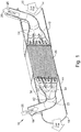
- the second fluid inlet 14 and second fluid outlet 16 are axially aligned with one another and are substantially equal in flow area.
- the body 12 is configured so as to allow the heat exchanger 10 to replace a section of a fluid duct, or the like, carrying the second fluid 30.
- fractal channel here describes the repeatedly diverging structure of the channels 22, 24, whereby the channel 22, 24 repeatedly splits into two or more smaller sub-channels 36 along its length. Such structures are sometimes also known as multi-furcating channels.
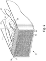
- Figure 2 shows a cut-away view of the first fractal channel 22 and the heat exchanger core 26.
- the second fractal channel 24 in Figure 1 is a mirror of the structure of the first fractal channel 22, i.e. mirrored about a plane perpendicular to the flow direction of the fluid.
- the structure of the second fractal channel 24 is identical to the structure of the first fractal channel 22, but oriented in reverse.
- the first fractal stage comprises a parent channel 42 with the largest diameter, corresponding to the diameter of the second fluid inlet conduit 18.
- the parent channel 42 of the first fractal stage reaches a first divergence point 34 where the parent channel 42 splits into nine sub-channels 36, the middle three of which are visible in the cut-away of Figure 2 , each having a smaller diameter than the parent channel 42.
- the outer sub-channels 36 initially diverge away from each other and a central axis of the parent channel 42, whilst the central sub-channel 36 continues along the central axis.
- the outer sub-channels 36 are curved such that after a given length the direction of the sub-channels become approximately parallel to the central axis of the parent channel 42.
- the nine sub-channels 36 are arranged in a 3x3 grid and are 90 degrees rotationally symmetrical.
- the nine sub-channels 36 split rotationally symmetrically from the parent channel 42, wherein each sub-channel 26 is offset by 90 degrees from neighbouring sub-channels 36.
- Each sub-channel 36 then forms a parent channel in the next fractal stage.
- the second fractal stage of the fractal channel 22 thus comprises nine parent channels, corresponding to the nine sub-channels 36 of the first fractal stage.
- Each parent channel of the second fractal stage reaches a second divergence point 34 and splits into a plurality of additional sub-channels which diverge and curve in the same way as for the first fractal stage.
- These nine parent channels divide into 49 sub-channels arranged in a 7x7 grid.
- the sub-channels 36 of the second fractal stage form parent channels of a third fractal stage, in which those parent channels diverge at a third divergence point 34 to form 225 sub-channels arranged in a 15x15 grid.
- the sub-channels 36 of the third fractal stage subsequently form the fourth fractal stage which split in the same manner at a fourth divergence point to form 961 channels in a 31x31 grid.
- the sub-channels 36 of the fourth fractal stage in the first fractal 22 are directly connected to alternative channels of the heat exchanger core 26.
- the sub-channels 36 of the fourth fractal stage in the second fractal channel 24 are directly, fluidly, connected to a second end of the heat exchanger core 26.
- the structure of the second fractal channel 24 is identical to the structure of the first fractal channel 22.
- the individual sub-channels 36 of each fractal stage have a smaller diameter than the respective parent channel of that fractal stage from which they have divided.
- the total cross sectional flow area of the sub-channels 36 within each particular fractal stage is substantially equal, therefore the total cross sectional flow area through the fractal channel 22 remains substantially constant. This prevents any pressure drop from occurring in the first fluid 28.
- Figure 2 also shows details of the heat exchanger core 26.
- the heat exchanger core 26 is of a single, solid, construction defining a plurality of parallel channels within it.
- the plurality of channels within the heat exchanger core 26 are closely packed so that the wall of one channel also forms at least a portion of the wall for adjacent channels.
- the plurality of parallel channels comprises a plurality of first fluid channels 38 and a plurality of second fluid channels 40.
- the heat exchanger core 26 is a single, solid, construction it will be more resistant to vibration damage than a heat exchanger comprising unsupported or intermittently supported parallel tubes.
- the second fluid channels 40 in the heat exchanger core 26 are supplied with the second fluid 30 at a first end of the heat exchanger core 26 from the second fluid inlet 14 of the body 12.
- the first fluid channels 38 are supplied with the first fluid 28 at a second end of the heat exchanger core 26 by the first fractal channel 22.
- the second fluid 30 exits the heat exchanger core 26 at the second end and travels around the first fractal channel 22 to the first fluid outlet 16.
- the first fluid 28 exits the heat exchanger core 26 at the first end via the second fractal channel 24.
- the heat exchanger core 26 comprises an approximately equal number of first fluid channels 38 and second fluid channels 40.
- the first fluid channels 38 are arranged in a 31x31 grid (i.e. with 961 first fluid channels 38), whilst the second fluid channels are arranged in a 30x30 grid (i.e. with 900 second fluid channels 40).
- the first and second channels 38, 40 within the heat exchanger core 26 each have a square diamond cross-sectional shape and are arranged in a grid configuration.
- the first and second channels 38, 40 are arranged in an alternating fashion such that every side of each first channel 38 will act as a primary heat transfer surface with an adjacent second channel 40, and vice versa. It will be appreciated that any cross sectional shape can be used for the first and second channels 38, 40, for example the cross section of the channels 38, 40 may be diamond, rectangular, circular or any other shape. It is also possible for some of the channels 38, 40 to have different cross section shapes than other channels, this will however require different wall thicknesses to accommodate for it.
- the total cross-sectional flow area of all the first fluid channels 40 is equal to the total cross-sectional flow area of both the first and second fractal channels 22, 24. This prevents pressure fluctuations in the first fluid 28.
- the total cross-sectional flow area of the second fluid channels 38 is approximately equal to the total cross-sectional flow area of the first fluid channels 40. In the illustrated embodiment, this is less than the cross sectional flow area of the second fluid inlet 14 and second fluid outlet 16. However, if it is necessary to avoid pressure variations in the first fluid 28 as well as the second fluid 30, then the body 12 may be designed such that the total cross-sectional flow area of the first fluid channels 38 is approximately equal to the cross-sectional flow area of the second fluid inlet 14 and the second fluid outlet 16.
- the heat exchanger core 26 is arranged so that all of the first fluid 28 and all of the second fluid 30 passes respectively through the first and second channels 38, 40 of the heat exchanger core 26.
- the overall cross-section of the heat exchanger core 26 is rectangular, however it could be circular or any other cross section.
- the first fluid inlet conduit 18 and the first fluid outlet conduit 20 extend through a side wall of the body 12 at an angle to the longitudinal direction of the duct 12.
- the angle between the ends of the second fluid inlet conduit 18 and the second fluid outlet conduit 20 is approximately 45 degrees, however it will be appreciated that the angle can be up to 90 degrees.
- the first fluid inlet conduit 18 is curved so that the first parent channel 42 is parallel to the longitudinal direction of the body 12.
- FIG 3 shows how the heat exchanger 10 can be manufactured by additive manufacturing.
- the heat exchanger 10 can be manufactured using additive manufacturing as one piece.
- the heat exchanger 10 is shown in Figure 3 as being printed from the second fluid outlet 16 to the second fluid inlet 14, wherein the second fluid outlet 16 forms the bottom surface during printing. Therefore for the first fractal channel 22 (closest to the bottom surface) the first parent channel 42 will be printed first ending with the smallest sub-channel 36. For the second fractal channel 24 (nearest to the top surface) the smallest sub-channels 36 will be printed first ending with the first parent channel 42.
- Figures 4 to 7 show a second heat exchanger 10, which has been found to improve second fluid flow around the fractal channels 22, 24 and also to simplify the additive manufacturing process.
- the structure of the second heat exchanger 10 is similar to that of the first heat exchanger 10. Accordingly, only the differences between the heat exchangers will be discussed. Components of the second heat exchanger 10 that are similar to those of the first heat exchanger 10 are labelled with the same reference sign, and will not be described again.
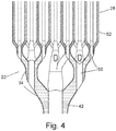
- Figure 4 shows a first fractal channel 22 for the second heat exchanger 10, where a bypass tube 50 is provided at each divergence of the fractal channel 22.
- each parent channel and sub-channel includes a bypass tube 50 which extends in the longitudinal direction of the heat exchanger 10.
- Each bypass tube 50 is axially aligned with a parent channel of the first fractal channel 24.
- Each bypass tube 50 extends between an outer surface of a parent channel along the length of the parent channel to where the divergence point 34 was previously, where it emerges between the sub-channels after divergence.
- the outer surface of the parent channel from which the bypass tube 50 extends is the point at which the parent channel curves inward from the previous diversion, i.e. where the sub-channels of the preceding fractal stage change from diverging away from the central axis of the parent channel 42 to being parallel to the central axis of the parent channel 42.
- the second heat exchanger core 26 comprises a plurality of first fluid tubes 52 which extend between the smallest sub-channels 36 of the first fractal 22 to the smallest sub-channels of the second fractal 24.
- the fractal channels 22, 24 and first fluid tubes 52 of the heat exchanger core 26 can be used to transport a first fluid 28 and the space surrounding the fractal channels 22, 24 and plurality of fluid tubes 52 of the heat exchanger core 26 can be filled with the second fluid 30.
- the second fluid 30 then enters the heat exchanger core 26 at a first end.
- the heat exchanger core is a single, solid, construction of closely-packed tubes
- the second fluid 30 travels through the second fluid channels 38 of the heat exchanger core 26 and leaves via the second end of the heat exchanger core 26.
- the heat exchanger core 26 comprises a plurality of discrete first fluid tubes 52 connecting the smallest sub-channels 36 of the first fractal channel 22 and second fractal channel 24
- the second fluid 30 travels around the first fluid tubes 52.
- the second fluid 30 then leaves the second heat exchanger 10 at the second fluid outlet 16.
- the first fluid 28 enters the heat exchanger 10 via the first fluid inlet conduit 18 at an angle to the longitudinal direction off the duct 12.
- the first fluid 28 then travels through the first fractal channel 22 and, in the case of Figure 1 to 3 enters the first fluid channels 38 at the second end of the heat exchanger core 26.
- the first fluid 28 travels through the first fractal channel 22 and enter the plurality of first fluid tubes 52.
- the first fluid 28 travels along the first fluid channels 38 or the first fluid tubes 52 of the heat exchanger core 26 and then enters the second fractal channel 24.
- the first fluid 28 then exits the heat exchanger 10 via the first fluid outlet conduit 20.
- the first and second fractal channels 22, 24 are positioned within the body 12 and hence the fractal channels 22, 24 are submerged in the flow path of the second fluid 30. This means that heat transfer will take place between the first and second fluids 28, 30 as they pass around and through the fractal channels 22, 24, respectively, as well as when they flow through the heat exchanger core 26.
- bypass tubes 50 allows the second fluid to reach the middle of each sub-channel in the fractal channels 22, 24 and thus the distribution of the second fluid is much more uniform.
- the bypass tubes 50 also mean that the primary heat transfer surface area is increased.
- the heat exchanger utilizes counter flow, although parallel flow can also be utilized where the first fluid flow and the second fluid flow are in the same direction.
- the counter flow arrangement means that the temperature difference will be more uniform along the length of the heat exchanger core 26 than if parallel flow is utilised. This prevents the hottest fluid from being in contact with the coldest fluid and hence reduces the thermal stresses on the thin channels and walls of the fractal channels 22, 24.
- Figure 6 shows an isometric view of a first fluid circuit of the second heat exchanger 10 and Figure 7 shows an end view of the first fractal channel 22 of the second heat exchanger 10.
- the first parent channel 42 of the first fractal heat exchanger 22 splits into 8 sub-channels 36 in a first fractal stage.
- the parent channel 42 comprises a bypass tube 50 which extends from one surface of the parent channel 42 in a longitudinal direction, parallel to the second fluid flow path, through to the first divergence point 34.
- Each of the eight sub-channels 36 also comprise bypass tubes 50 which extend from one surface of the sub-channel in a longitudinal direction, parallel to the second fluid flow path, through to the next divergence point 34. As shown in Figure 7 , the bypass tube 50 provides a clear path for the second fluid 30 to travel through.
- Each of the 8 sub-channels forms a parent channel for a second fractal stage.
- each of the 8 parent channels divide into a further 5 sub-channels resulting in 40 sub-channels in the second fractal stage.
- the distribution of the 5 sub-channels around each corresponding parent channel is rotated by 90 degrees for every two groups of sub-channels about the fractal channel.
- the parent channel in the top left splits into 5 sub-channels whereby two of the sub-channels are located on the same horizontal plane as the parent channel and three sub-channels are located on a horizontal plane above the plane of the parent channel.
- two sub-channels are located on the same vertical plane as the corresponding parent channel and three sub-channels are located on a vertical plane to the right of the corresponding parent channel.
- the sub-channels of the second fractal stage therefore maintain 90° rotational symmetry.
- the 40 sub-channels of the second fractal stage subsequently form the parent channels for a third fractal stage.
- the parent channels of the third fractal stage each split into four sub-channels, thus forming 160 sub-channels.
- the 160 sub-channels then extend straight as fluid tubes 52 to the 256 sub-channels of the second fractal channel 24.
- bypass tubes 50 have thus far only been described in conjunction with the first fractal channel 22 of the second heat exchanger 10 shown in the Figure 4-7 . It will be appreciated that the same construction may be applied to the second fractal channel 24 of the second heat exchanger 10. Furthermore, bypass tubes 50 may be incorporated into the fractal channels 22, 24 used for the first heat exchanger 10, i.e. comprising a heat exchanger core 26 formed of a single, solid construction defining a plurality of parallel channels in a close-packed configuration.
- the heat exchanger 10 can be manufactured by additive manufacturing. This allows for the shape of the heat exchanger to be adapted according to accommodate existing systems.
- the heat exchanger 10 can be printed by additive manufacture from any material suitable for the intended operating conditions. The type of material depends on the specific application of the heat exchanger 10.
- Exemplary materials that may be used are aluminium, steel, nickel, alloys or titanium or superalloys such as Inconel 625. Aluminium may be suitable for low to medium temperature applications. Polymers may be suitable for low temperature applications. Polymers may also be used if it is desirable for the heat exchanger to be flexible.
Landscapes
- Engineering & Computer Science (AREA)
- Physics & Mathematics (AREA)
- Thermal Sciences (AREA)
- Mechanical Engineering (AREA)
- General Engineering & Computer Science (AREA)
- Geometry (AREA)
- Chemical & Material Sciences (AREA)
- Manufacturing & Machinery (AREA)
- Materials Engineering (AREA)
- Heat-Exchange Devices With Radiators And Conduit Assemblies (AREA)
Priority Applications (2)
| Application Number | Priority Date | Filing Date | Title |
|---|---|---|---|
| EP20153726.3A EP3855106B1 (de) | 2020-01-24 | 2020-01-24 | Fraktaler wärmetauscher mit kanal |
| US17/147,817 US11280554B2 (en) | 2020-01-24 | 2021-01-13 | Fractal heat exchanger with bypass |
Applications Claiming Priority (1)
| Application Number | Priority Date | Filing Date | Title |
|---|---|---|---|
| EP20153726.3A EP3855106B1 (de) | 2020-01-24 | 2020-01-24 | Fraktaler wärmetauscher mit kanal |
Publications (2)
| Publication Number | Publication Date |
|---|---|
| EP3855106A1 true EP3855106A1 (de) | 2021-07-28 |
| EP3855106B1 EP3855106B1 (de) | 2022-12-14 |
Family
ID=69232793
Family Applications (1)
| Application Number | Title | Priority Date | Filing Date |
|---|---|---|---|
| EP20153726.3A Active EP3855106B1 (de) | 2020-01-24 | 2020-01-24 | Fraktaler wärmetauscher mit kanal |
Country Status (2)
| Country | Link |
|---|---|
| US (1) | US11280554B2 (de) |
| EP (1) | EP3855106B1 (de) |
Cited By (1)
| Publication number | Priority date | Publication date | Assignee | Title |
|---|---|---|---|---|
| US20240271889A1 (en) * | 2023-02-14 | 2024-08-15 | Hamilton Sundstrand Corporation | Flow-modifying heat exchanger core tubes |
Families Citing this family (5)
| Publication number | Priority date | Publication date | Assignee | Title |
|---|---|---|---|---|
| AU2018255490B2 (en) * | 2017-04-21 | 2023-02-02 | Commonwealth Scientific And Industrial Research Organisation | Flow distribution system |
| US10955200B2 (en) * | 2018-07-13 | 2021-03-23 | General Electric Company | Heat exchangers having a three-dimensional lattice structure with baffle cells and methods of forming baffles in a three-dimensional lattice structure of a heat exchanger |
| IT201800010006A1 (it) * | 2018-11-02 | 2020-05-02 | Sumitomo Riko Co Ltd | Scambiatore di calore interno |
| US11493286B1 (en) | 2021-10-12 | 2022-11-08 | Hamilton Sundstrand Corporation | Header for high-pressure heat exchanger |
| FR3130949B1 (fr) * | 2021-12-16 | 2024-01-05 | Commissariat Energie Atomique | Echangeur de chaleur à calandre et tubes |
Citations (6)
| Publication number | Priority date | Publication date | Assignee | Title |
|---|---|---|---|---|
| US20130206374A1 (en) * | 2010-03-15 | 2013-08-15 | The Trustees Of Dartmouth College | Geometry of heat exchanger with high efficiency |
| US20170030651A1 (en) * | 2015-07-30 | 2017-02-02 | General Electric Company | Counter-flow heat exchanger with helical passages |
| US20190024988A1 (en) * | 2017-07-18 | 2019-01-24 | General Electric Company | Header assembly for a heat exchanger |
| DE202019102083U1 (de) * | 2019-04-11 | 2019-04-18 | Mahle International Gmbh | Kühlfluiddurchströmte Wellrippenanordnung und Kraftfahrzeugbauteil |
| WO2019171078A1 (en) * | 2018-03-09 | 2019-09-12 | Bae Systems Plc | Heat exchanger |
| WO2020109707A1 (fr) * | 2018-11-28 | 2020-06-04 | Liebherr-Aerospace Toulouse Sas | Échangeur de chaleur et système de refroidissement d'un fluide comprenant un tel échangeur de chaleur |
Family Cites Families (8)
| Publication number | Priority date | Publication date | Assignee | Title |
|---|---|---|---|---|
| GB0521826D0 (en) * | 2005-10-26 | 2005-12-07 | Rolls Royce Plc | Wall cooling arrangement |
| US10041745B2 (en) * | 2010-05-04 | 2018-08-07 | Fractal Heatsink Technologies LLC | Fractal heat transfer device |
| CA2962484A1 (en) | 2014-10-07 | 2016-04-14 | Unison Industries, Llc | Multi-branch furcating flow heat exchanger |
| US10088250B2 (en) * | 2016-01-12 | 2018-10-02 | Hamilton Sundstrand Corporation | Heat exchangers |
| SG11201901767UA (en) * | 2016-09-08 | 2019-03-28 | Additive Rocket Corp | Fractal fluid passages apparatus |
| US10107555B1 (en) * | 2017-04-21 | 2018-10-23 | Unison Industries, Llc | Heat exchanger assembly |
| CN111433549A (zh) | 2017-07-17 | 2020-07-17 | 分形散热器技术有限责任公司 | 多重分形散热器系统及方法 |
| WO2019060563A1 (en) | 2017-09-20 | 2019-03-28 | Additive Rocket Corporation | ADDITIVE MANUFACTURING CONSTRUCTIONS AND METHODS OF MANUFACTURING THE SAME |
-
2020
- 2020-01-24 EP EP20153726.3A patent/EP3855106B1/de active Active
-
2021
- 2021-01-13 US US17/147,817 patent/US11280554B2/en active Active
Patent Citations (6)
| Publication number | Priority date | Publication date | Assignee | Title |
|---|---|---|---|---|
| US20130206374A1 (en) * | 2010-03-15 | 2013-08-15 | The Trustees Of Dartmouth College | Geometry of heat exchanger with high efficiency |
| US20170030651A1 (en) * | 2015-07-30 | 2017-02-02 | General Electric Company | Counter-flow heat exchanger with helical passages |
| US20190024988A1 (en) * | 2017-07-18 | 2019-01-24 | General Electric Company | Header assembly for a heat exchanger |
| WO2019171078A1 (en) * | 2018-03-09 | 2019-09-12 | Bae Systems Plc | Heat exchanger |
| WO2020109707A1 (fr) * | 2018-11-28 | 2020-06-04 | Liebherr-Aerospace Toulouse Sas | Échangeur de chaleur et système de refroidissement d'un fluide comprenant un tel échangeur de chaleur |
| DE202019102083U1 (de) * | 2019-04-11 | 2019-04-18 | Mahle International Gmbh | Kühlfluiddurchströmte Wellrippenanordnung und Kraftfahrzeugbauteil |
Cited By (2)
| Publication number | Priority date | Publication date | Assignee | Title |
|---|---|---|---|---|
| US20240271889A1 (en) * | 2023-02-14 | 2024-08-15 | Hamilton Sundstrand Corporation | Flow-modifying heat exchanger core tubes |
| US12516893B2 (en) * | 2023-02-14 | 2026-01-06 | Hamilton Sundstrand Corporation | Heat exchangers with flow-modifying heat exchanger core tubes |
Also Published As
| Publication number | Publication date |
|---|---|
| EP3855106B1 (de) | 2022-12-14 |
| US11280554B2 (en) | 2022-03-22 |
| US20210231381A1 (en) | 2021-07-29 |
Similar Documents
| Publication | Publication Date | Title |
|---|---|---|
| EP3855106B1 (de) | Fraktaler wärmetauscher mit kanal | |
| US12038236B2 (en) | Fractal heat exchanger | |
| EP3249336B1 (de) | Wärmetauscher mit gespaltenen einheitszellen | |
| US10107555B1 (en) | Heat exchanger assembly | |
| US20220282931A1 (en) | Heat exchanger device | |
| US20200080796A1 (en) | Additive manufactured heat exchanger | |
| US20110226448A1 (en) | Heat exchanger having winding channels | |
| US20180045472A1 (en) | Heat exchanger device | |
| US12449207B2 (en) | Multifurcating heat exchanger with independent baffles | |
| EP3196584B1 (de) | Wärmetauscher mit angrenzenden ein- und auslässen | |
| EP2840342B1 (de) | Wärmetauscher und kühlzyklusvorrichtung | |
| CN115597420A (zh) | 一种交错逆流式预冷换热器 | |
| US11988460B2 (en) | Method of using an indirect heat exchanger and facility for processing liquefied natural gas comprising such heat exchanger | |
| US10502501B1 (en) | Louvered elliptical tube micro-lattice heat exchangers | |
| US12173971B2 (en) | Helical fractal heat exchanger | |
| US20080190594A1 (en) | Heat Exchanger Device for Rapid Heating or Cooling of Fluids | |
| EP3196581B1 (de) | Wärmetauscher mit mittelverteiler und wärmeseparator | |
| CN120739616A (zh) | 飞行器用预冷换热器以及飞行器 | |
| EP3569962A1 (de) | Wasserwärmetauscher | |
| Mahapatra | Design Of 3-Stream (He-He-He) Plate-Fin Heat Exchanger For Helium Plant | |
| KR20160025396A (ko) | 대향유동 열교환기 및 이들로 이루어진 열교환기 집합체 |
Legal Events
| Date | Code | Title | Description |
|---|---|---|---|
| PUAI | Public reference made under article 153(3) epc to a published international application that has entered the european phase |
Free format text: ORIGINAL CODE: 0009012 |
|
| STAA | Information on the status of an ep patent application or granted ep patent |
Free format text: STATUS: THE APPLICATION HAS BEEN PUBLISHED |
|
| AK | Designated contracting states |
Kind code of ref document: A1 Designated state(s): AL AT BE BG CH CY CZ DE DK EE ES FI FR GB GR HR HU IE IS IT LI LT LU LV MC MK MT NL NO PL PT RO RS SE SI SK SM TR |
|
| STAA | Information on the status of an ep patent application or granted ep patent |
Free format text: STATUS: REQUEST FOR EXAMINATION WAS MADE |
|
| 17P | Request for examination filed |
Effective date: 20220120 |
|
| RBV | Designated contracting states (corrected) |
Designated state(s): AL AT BE BG CH CY CZ DE DK EE ES FI FR GB GR HR HU IE IS IT LI LT LU LV MC MK MT NL NO PL PT RO RS SE SI SK SM TR |
|
| GRAP | Despatch of communication of intention to grant a patent |
Free format text: ORIGINAL CODE: EPIDOSNIGR1 |
|
| STAA | Information on the status of an ep patent application or granted ep patent |
Free format text: STATUS: GRANT OF PATENT IS INTENDED |
|
| INTG | Intention to grant announced |
Effective date: 20220622 |
|
| GRAS | Grant fee paid |
Free format text: ORIGINAL CODE: EPIDOSNIGR3 |
|
| GRAA | (expected) grant |
Free format text: ORIGINAL CODE: 0009210 |
|
| STAA | Information on the status of an ep patent application or granted ep patent |
Free format text: STATUS: THE PATENT HAS BEEN GRANTED |
|
| AK | Designated contracting states |
Kind code of ref document: B1 Designated state(s): AL AT BE BG CH CY CZ DE DK EE ES FI FR GB GR HR HU IE IS IT LI LT LU LV MC MK MT NL NO PL PT RO RS SE SI SK SM TR |
|
| REG | Reference to a national code |
Ref country code: GB Ref legal event code: FG4D |
|
| REG | Reference to a national code |
Ref country code: CH Ref legal event code: EP |
|
| REG | Reference to a national code |
Ref country code: DE Ref legal event code: R096 Ref document number: 602020006828 Country of ref document: DE |
|
| REG | Reference to a national code |
Ref country code: IE Ref legal event code: FG4D |
|
| REG | Reference to a national code |
Ref country code: AT Ref legal event code: REF Ref document number: 1537920 Country of ref document: AT Kind code of ref document: T Effective date: 20230115 |
|
| REG | Reference to a national code |
Ref country code: LT Ref legal event code: MG9D |
|
| REG | Reference to a national code |
Ref country code: NL Ref legal event code: MP Effective date: 20221214 |
|
| PG25 | Lapsed in a contracting state [announced via postgrant information from national office to epo] |
Ref country code: SE Free format text: LAPSE BECAUSE OF FAILURE TO SUBMIT A TRANSLATION OF THE DESCRIPTION OR TO PAY THE FEE WITHIN THE PRESCRIBED TIME-LIMIT Effective date: 20221214 Ref country code: NO Free format text: LAPSE BECAUSE OF FAILURE TO SUBMIT A TRANSLATION OF THE DESCRIPTION OR TO PAY THE FEE WITHIN THE PRESCRIBED TIME-LIMIT Effective date: 20230314 Ref country code: LT Free format text: LAPSE BECAUSE OF FAILURE TO SUBMIT A TRANSLATION OF THE DESCRIPTION OR TO PAY THE FEE WITHIN THE PRESCRIBED TIME-LIMIT Effective date: 20221214 Ref country code: FI Free format text: LAPSE BECAUSE OF FAILURE TO SUBMIT A TRANSLATION OF THE DESCRIPTION OR TO PAY THE FEE WITHIN THE PRESCRIBED TIME-LIMIT Effective date: 20221214 |
|
| REG | Reference to a national code |
Ref country code: AT Ref legal event code: MK05 Ref document number: 1537920 Country of ref document: AT Kind code of ref document: T Effective date: 20221214 |
|
| PG25 | Lapsed in a contracting state [announced via postgrant information from national office to epo] |
Ref country code: RS Free format text: LAPSE BECAUSE OF FAILURE TO SUBMIT A TRANSLATION OF THE DESCRIPTION OR TO PAY THE FEE WITHIN THE PRESCRIBED TIME-LIMIT Effective date: 20221214 Ref country code: LV Free format text: LAPSE BECAUSE OF FAILURE TO SUBMIT A TRANSLATION OF THE DESCRIPTION OR TO PAY THE FEE WITHIN THE PRESCRIBED TIME-LIMIT Effective date: 20221214 Ref country code: HR Free format text: LAPSE BECAUSE OF FAILURE TO SUBMIT A TRANSLATION OF THE DESCRIPTION OR TO PAY THE FEE WITHIN THE PRESCRIBED TIME-LIMIT Effective date: 20221214 Ref country code: GR Free format text: LAPSE BECAUSE OF FAILURE TO SUBMIT A TRANSLATION OF THE DESCRIPTION OR TO PAY THE FEE WITHIN THE PRESCRIBED TIME-LIMIT Effective date: 20230315 |
|
| PG25 | Lapsed in a contracting state [announced via postgrant information from national office to epo] |
Ref country code: NL Free format text: LAPSE BECAUSE OF FAILURE TO SUBMIT A TRANSLATION OF THE DESCRIPTION OR TO PAY THE FEE WITHIN THE PRESCRIBED TIME-LIMIT Effective date: 20221214 |
|
| P01 | Opt-out of the competence of the unified patent court (upc) registered |
Effective date: 20230603 |
|
| PG25 | Lapsed in a contracting state [announced via postgrant information from national office to epo] |
Ref country code: SM Free format text: LAPSE BECAUSE OF FAILURE TO SUBMIT A TRANSLATION OF THE DESCRIPTION OR TO PAY THE FEE WITHIN THE PRESCRIBED TIME-LIMIT Effective date: 20221214 Ref country code: RO Free format text: LAPSE BECAUSE OF FAILURE TO SUBMIT A TRANSLATION OF THE DESCRIPTION OR TO PAY THE FEE WITHIN THE PRESCRIBED TIME-LIMIT Effective date: 20221214 Ref country code: PT Free format text: LAPSE BECAUSE OF FAILURE TO SUBMIT A TRANSLATION OF THE DESCRIPTION OR TO PAY THE FEE WITHIN THE PRESCRIBED TIME-LIMIT Effective date: 20230414 Ref country code: ES Free format text: LAPSE BECAUSE OF FAILURE TO SUBMIT A TRANSLATION OF THE DESCRIPTION OR TO PAY THE FEE WITHIN THE PRESCRIBED TIME-LIMIT Effective date: 20221214 Ref country code: EE Free format text: LAPSE BECAUSE OF FAILURE TO SUBMIT A TRANSLATION OF THE DESCRIPTION OR TO PAY THE FEE WITHIN THE PRESCRIBED TIME-LIMIT Effective date: 20221214 Ref country code: CZ Free format text: LAPSE BECAUSE OF FAILURE TO SUBMIT A TRANSLATION OF THE DESCRIPTION OR TO PAY THE FEE WITHIN THE PRESCRIBED TIME-LIMIT Effective date: 20221214 Ref country code: AT Free format text: LAPSE BECAUSE OF FAILURE TO SUBMIT A TRANSLATION OF THE DESCRIPTION OR TO PAY THE FEE WITHIN THE PRESCRIBED TIME-LIMIT Effective date: 20221214 |
|
| PG25 | Lapsed in a contracting state [announced via postgrant information from national office to epo] |
Ref country code: SK Free format text: LAPSE BECAUSE OF FAILURE TO SUBMIT A TRANSLATION OF THE DESCRIPTION OR TO PAY THE FEE WITHIN THE PRESCRIBED TIME-LIMIT Effective date: 20221214 Ref country code: PL Free format text: LAPSE BECAUSE OF FAILURE TO SUBMIT A TRANSLATION OF THE DESCRIPTION OR TO PAY THE FEE WITHIN THE PRESCRIBED TIME-LIMIT Effective date: 20221214 Ref country code: IS Free format text: LAPSE BECAUSE OF FAILURE TO SUBMIT A TRANSLATION OF THE DESCRIPTION OR TO PAY THE FEE WITHIN THE PRESCRIBED TIME-LIMIT Effective date: 20230414 Ref country code: AL Free format text: LAPSE BECAUSE OF FAILURE TO SUBMIT A TRANSLATION OF THE DESCRIPTION OR TO PAY THE FEE WITHIN THE PRESCRIBED TIME-LIMIT Effective date: 20221214 |
|
| REG | Reference to a national code |
Ref country code: CH Ref legal event code: PL |
|
| REG | Reference to a national code |
Ref country code: DE Ref legal event code: R097 Ref document number: 602020006828 Country of ref document: DE |
|
| PG25 | Lapsed in a contracting state [announced via postgrant information from national office to epo] |
Ref country code: MC Free format text: LAPSE BECAUSE OF FAILURE TO SUBMIT A TRANSLATION OF THE DESCRIPTION OR TO PAY THE FEE WITHIN THE PRESCRIBED TIME-LIMIT Effective date: 20221214 Ref country code: LU Free format text: LAPSE BECAUSE OF NON-PAYMENT OF DUE FEES Effective date: 20230124 |
|
| REG | Reference to a national code |
Ref country code: BE Ref legal event code: MM Effective date: 20230131 |
|
| PLBE | No opposition filed within time limit |
Free format text: ORIGINAL CODE: 0009261 |
|
| STAA | Information on the status of an ep patent application or granted ep patent |
Free format text: STATUS: NO OPPOSITION FILED WITHIN TIME LIMIT |
|
| PG25 | Lapsed in a contracting state [announced via postgrant information from national office to epo] |
Ref country code: LI Free format text: LAPSE BECAUSE OF NON-PAYMENT OF DUE FEES Effective date: 20230131 Ref country code: DK Free format text: LAPSE BECAUSE OF FAILURE TO SUBMIT A TRANSLATION OF THE DESCRIPTION OR TO PAY THE FEE WITHIN THE PRESCRIBED TIME-LIMIT Effective date: 20221214 Ref country code: CH Free format text: LAPSE BECAUSE OF NON-PAYMENT OF DUE FEES Effective date: 20230131 |
|
| 26N | No opposition filed |
Effective date: 20230915 |
|
| PG25 | Lapsed in a contracting state [announced via postgrant information from national office to epo] |
Ref country code: SI Free format text: LAPSE BECAUSE OF FAILURE TO SUBMIT A TRANSLATION OF THE DESCRIPTION OR TO PAY THE FEE WITHIN THE PRESCRIBED TIME-LIMIT Effective date: 20221214 Ref country code: BE Free format text: LAPSE BECAUSE OF NON-PAYMENT OF DUE FEES Effective date: 20230131 |
|
| PG25 | Lapsed in a contracting state [announced via postgrant information from national office to epo] |
Ref country code: IE Free format text: LAPSE BECAUSE OF NON-PAYMENT OF DUE FEES Effective date: 20230124 |
|
| PG25 | Lapsed in a contracting state [announced via postgrant information from national office to epo] |
Ref country code: IT Free format text: LAPSE BECAUSE OF FAILURE TO SUBMIT A TRANSLATION OF THE DESCRIPTION OR TO PAY THE FEE WITHIN THE PRESCRIBED TIME-LIMIT Effective date: 20221214 |
|
| PG25 | Lapsed in a contracting state [announced via postgrant information from national office to epo] |
Ref country code: BG Free format text: LAPSE BECAUSE OF FAILURE TO SUBMIT A TRANSLATION OF THE DESCRIPTION OR TO PAY THE FEE WITHIN THE PRESCRIBED TIME-LIMIT Effective date: 20221214 |
|
| PG25 | Lapsed in a contracting state [announced via postgrant information from national office to epo] |
Ref country code: BG Free format text: LAPSE BECAUSE OF FAILURE TO SUBMIT A TRANSLATION OF THE DESCRIPTION OR TO PAY THE FEE WITHIN THE PRESCRIBED TIME-LIMIT Effective date: 20221214 |
|
| PG25 | Lapsed in a contracting state [announced via postgrant information from national office to epo] |
Ref country code: CY Free format text: LAPSE BECAUSE OF FAILURE TO SUBMIT A TRANSLATION OF THE DESCRIPTION OR TO PAY THE FEE WITHIN THE PRESCRIBED TIME-LIMIT; INVALID AB INITIO Effective date: 20200124 |
|
| PG25 | Lapsed in a contracting state [announced via postgrant information from national office to epo] |
Ref country code: HU Free format text: LAPSE BECAUSE OF FAILURE TO SUBMIT A TRANSLATION OF THE DESCRIPTION OR TO PAY THE FEE WITHIN THE PRESCRIBED TIME-LIMIT; INVALID AB INITIO Effective date: 20200124 |
|
| PG25 | Lapsed in a contracting state [announced via postgrant information from national office to epo] |
Ref country code: TR Free format text: LAPSE BECAUSE OF FAILURE TO SUBMIT A TRANSLATION OF THE DESCRIPTION OR TO PAY THE FEE WITHIN THE PRESCRIBED TIME-LIMIT Effective date: 20221214 |
|
| PGFP | Annual fee paid to national office [announced via postgrant information from national office to epo] |
Ref country code: GB Payment date: 20251220 Year of fee payment: 7 |
|
| PGFP | Annual fee paid to national office [announced via postgrant information from national office to epo] |
Ref country code: FR Payment date: 20251217 Year of fee payment: 7 |
|
| PGFP | Annual fee paid to national office [announced via postgrant information from national office to epo] |
Ref country code: DE Payment date: 20251217 Year of fee payment: 7 |