EP3855281B1 - Montageanordnung für ein steuerpedal eines kraftfahrzeugs - Google Patents
Montageanordnung für ein steuerpedal eines kraftfahrzeugs Download PDFInfo
- Publication number
- EP3855281B1 EP3855281B1 EP20209262.3A EP20209262A EP3855281B1 EP 3855281 B1 EP3855281 B1 EP 3855281B1 EP 20209262 A EP20209262 A EP 20209262A EP 3855281 B1 EP3855281 B1 EP 3855281B1
- Authority
- EP
- European Patent Office
- Prior art keywords
- locking means
- mounting assembly
- wall
- locking
- clamp
- Prior art date
- Legal status (The legal status is an assumption and is not a legal conclusion. Google has not performed a legal analysis and makes no representation as to the accuracy of the status listed.)
- Active
Links
Images


Classifications
-
- G—PHYSICS
- G05—CONTROLLING; REGULATING
- G05G—CONTROL DEVICES OR SYSTEMS INSOFAR AS CHARACTERISED BY MECHANICAL FEATURES ONLY
- G05G1/00—Controlling members, e.g. knobs or handles; Assemblies or arrangements thereof; Indicating position of controlling members
- G05G1/30—Controlling members actuated by foot
- G05G1/44—Controlling members actuated by foot pivoting
-
- B—PERFORMING OPERATIONS; TRANSPORTING
- B60—VEHICLES IN GENERAL
- B60K—ARRANGEMENT OR MOUNTING OF PROPULSION UNITS OR OF TRANSMISSIONS IN VEHICLES; ARRANGEMENT OR MOUNTING OF PLURAL DIVERSE PRIME-MOVERS IN VEHICLES; AUXILIARY DRIVES FOR VEHICLES; INSTRUMENTATION OR DASHBOARDS FOR VEHICLES; ARRANGEMENTS IN CONNECTION WITH COOLING, AIR INTAKE, GAS EXHAUST OR FUEL SUPPLY OF PROPULSION UNITS IN VEHICLES
- B60K23/00—Arrangement or mounting of control devices for vehicle transmissions, or parts thereof, not otherwise provided for
- B60K23/02—Arrangement or mounting of control devices for vehicle transmissions, or parts thereof, not otherwise provided for for main transmission clutches
-
- B—PERFORMING OPERATIONS; TRANSPORTING
- B60—VEHICLES IN GENERAL
- B60K—ARRANGEMENT OR MOUNTING OF PROPULSION UNITS OR OF TRANSMISSIONS IN VEHICLES; ARRANGEMENT OR MOUNTING OF PLURAL DIVERSE PRIME-MOVERS IN VEHICLES; AUXILIARY DRIVES FOR VEHICLES; INSTRUMENTATION OR DASHBOARDS FOR VEHICLES; ARRANGEMENTS IN CONNECTION WITH COOLING, AIR INTAKE, GAS EXHAUST OR FUEL SUPPLY OF PROPULSION UNITS IN VEHICLES
- B60K26/00—Arrangement or mounting of propulsion-unit control devices in vehicles
- B60K26/02—Arrangement or mounting of propulsion-unit control devices in vehicles of initiating means or elements
-
- B—PERFORMING OPERATIONS; TRANSPORTING
- B60—VEHICLES IN GENERAL
- B60T—VEHICLE BRAKE CONTROL SYSTEMS OR PARTS THEREOF; BRAKE CONTROL SYSTEMS OR PARTS THEREOF, IN GENERAL; ARRANGEMENT OF BRAKING ELEMENTS ON VEHICLES IN GENERAL; PORTABLE DEVICES FOR PREVENTING UNWANTED MOVEMENT OF VEHICLES; VEHICLE MODIFICATIONS TO FACILITATE COOLING OF BRAKES
- B60T7/00—Brake-action initiating means
- B60T7/02—Brake-action initiating means for personal initiation
- B60T7/04—Brake-action initiating means for personal initiation foot actuated
- B60T7/06—Disposition of pedal
Definitions
- the present invention relates generally to a mounting assembly for a control pedal of a vehicle which is cost efficient and time-saving both during production of parts of the mounting assembly as well as during assembly of the control pedal.
- the manufacturers strive towards a more time efficient and cost-conscious assembly of the vehicles, this to minimize the manufacturing cost. Further, the manufacturers also strive towards a simple design of the included components and sometimes also with integrated multiple functionalities which imply that less components are needed. A component design with few components that are time efficient to assembly are thus worth aiming at to achieve a cost efficient assembly.
- EP 1 233 321 discloses a pedal arm which pivots around a pivot axis at right angles to the pedal arm, and which is supported in a housing by a plastic bearing at each end of the pivot axis. Each end is fixed in the housing by a locking lug which is received in a pocket by the housing.
- EP 1 322 500 and EP 2 620 832 discloses alternative solutions for fixing a pedal arm to a housing with some kind of locking means arranged on a pivot axis.
- FIG. 1 Another mounting assembly for a control pedal in a motor vehicle is presented in EP 3 314 350 which is filed by the applicant and which claims priority from SE 1550871-6.
- This mounting assembly achieves an improved and shortened assembly time and comprises a pivot shaft extending between two walls, two locking means arranged to pivotally retain the pivot shaft in a use position between the walls and further a control pedal which is rigidly provided on the pivot shaft.
- the control pedal and the pivot shaft are rotatable around an axis of rotation.
- the mounting assembly is provided with two joints on respective sides of the pivot shaft. Each joint comprises a lock protrusion provided on a locking means for cooperation with an internal groove provided in each of the walls.
- the respective lock protrusion is arranged to engage with the internal groove of the wall when the locking means is in a use position.
- the locking means further comprises a rotating prevention protrusion extending radially from an outer surface of the locking means, which protrusion is arranged to engage with a stop arranged on the walls when the locking means is in the use position.
- Such a rotating prevention protrusion in co-operation with the stop prevents the locking means from rotating in relation to the wall when in the use position.
- An object of the present invention is to provide a mounting assembly for a control pedal of a vehicle, which is achieves a cost-efficient mounting assembly with improved and shortened assembly time.
- a further object is to provide an alternative mounting assembly compared to SE 1550871-6, still with a robust, and reliable mounting assembly and with freedom from play.
- the mounting assembly for a control pedal of a vehicle comprises two walls arranged in parallel in relation to each other and each wall having a respective through opening. Further, a pivot shaft extending between the walls, wherein the pivot shaft has its respective end inserted into the respective through opening and at least a control pedal is rigidly provided on the pivot shaft.
- the control pedal and pivot shaft are rotatable around an axis of rotation.
- two locking means are arranged to pivotally retain the pivot shaft between the walls by that the respective locking means is positioned onto the respective end of the pivot shaft and is inserted into the respective through opening of the respective wall.
- the respective through opening is arranged to receive one locking means and the respective through opening has a shape complementary to the outer circumferential shape of the locking means, so as to be able to insert the locking means into the through opening.
- the locking means is rotatable in the through opening from a first mounting position to a locked using position and the locking means further comprising at least one lock protrusion, which extends radially from an outer surface of a first axial end of the locking means.
- the respective wall of the mounting assembly comprises - on a first side which faces away from the other wall - at least one external locking clamp and at least one stop.
- the at least one lock protrusion of the locking means is arranged to engage with the locking clamp and the stop, when the locking means is in the locked using position, wherein a disengagement of the locking means is prevented.
- the clamp and the stop are positioned such as the lock protrusion is held in the locked using position, why the locking means is prevented from disengagement from using position in the through opening of the wall.
- the locking means having a lock protrusion arranged to engage with the locking clamp and the stop, a controlled rotational and axial movement of the locking means in relation to the wall is achieved when the locking means is rotated from the mounting position in the through opening to the locked using position.
- the locking means In the locked using position, the locking means is prevented from rotating in relation to the wall when in the locked using position and the locking means is further prevented from loosening from the through opening of the wall.
- the locking clamp comprises first and second shanks connected to each other by an elongate mid-section and the shanks are further fixedly attached to the first side of the wall and protrudes a first distance from the first side of the wall such as a receiving space is formed between the first side of the wall and the locking clamp.
- the receiving space is arranged for receiving the lock protrusion of the locking means when the locking means is rotated from mounting position to the using position.
- the lock protrusion passes the first shank of the clamp and moves further into the receiving space, i.e. under the clamp.
- the lock protrusion then passes over the stop and snaps in place between the stop and the second shank of the clamp, wherein a further rotation is prevented.
- the stop is arranged in line with the mid-section of the locking clamp and protrudes from the first side of the wall in direction towards the mid-section of the locking clamp.
- the distance between the top surface of the stop and the mid-section of the clamp is adopted to allow the lock protrusion to slide over the stop, when the locking means is rotated from the mounting position to the locked using position.
- the main object is that the clamp and the stop should prevent the rotation of the locking means in the locked using position.
- the stop may be arranged outside the mid-section of the clamp and further, the entire clamp may be positioned "outside" the through opening, that is outside the circumference of the trough hole of the wall (preferred) if seen in the axial direction of the locking means and the through opening.
- the stop is wedge-shaped with a tip, i.e. having a ramp-surface, and further an, in relation to the tip, opposite stop edge.
- the stop is arranged to, during the rotation of the locking means in the through opening - from the mounting position to the locked using position - guide the at least one lock protrusion towards the locked using position, in which position the lock protrusion is locked between the stop edge of the stop and the second shank of the locking clamp.
- the wedge-shape facilitates an easy mounting of the locking means to the locked using position, while rotating the locking means in the through opening, where the lock protrusion of the locking means slides over the beveled edge.
- the locking clamp is resilient. The reason for this is to achieve a certain flexibility in the clamp and by that enable a smooth and easy sliding of the lock protrusion over the ramp surface of the clamp. After this, the lock protrusion snaps over the stop edge and by that is safely locked in the locked using position.
- the lock protrusion comprises at least one chamfered side edge, which side edge extends radially from the outer surface of the of the locking means.
- the side edge is by that chamfered in the "rotation direction" which means that the side edge of the lock protrusion, which during rotation of the locking means from the mounting position to the locked using position first enters the receiving space of the locking clamp, is chamfered. That is so to speak the front side edge of the lock protrusion.
- the chamfering is provided to enable an easy sliding of the lock protrusion over the ramp-surface of the stop at the same time as it is held by the locking clamp.
- the lock protrusion also is chamfered on the opposite side edge, i.e. the back side edge of the lock protrusion. This enables an even easier rotation of the locking means from the mounting position to the locked using position.
- a midpoint of the mid-section of the locking clamp is displaced a distance relative the axis of rotation of the pivot shaft. This, for allowing the at least one lock protrusion to pass the first shank of the clamp and enter the receiving space, when the locking means is rotated into the through opening of the wall, from the mounting position to the locked using position. Seen from a top-view (or an outside) of the wall and in direction towards the mounted locking means in the through opening of the wall, i.e. seen in the axial direction of the pivot shaft and the locking means, the mid-point of the mid-section of the clamp is displaced in relation to the axis of rotation.
- the "entrance side" of the clamp is open for entrance of the lock protrusion and further, the locked using position where the lock protrusion is arranged between the stop and the second shank of the clamp substantially aligns with the axis of rotation.
- the locking means further comprises one or more first axial securing protrusions, which protrudes in a radial direction from an outer surface of the locking means, and the first axial securing protrusions are arranged at a second axial end of the locking means.
- the first axial securing protrusion is deflectable which provides a snapping outwardly at the backside of the wall when the locking means reaches an end position in the mounting position.
- the locking means further comprises one or more resilient tongues, which protrudes in a radial direction from an outer surface of the locking means.
- the resilient tongue is arranged at the outer surface of the locking means. Since the respective through opening of the wall has a shape complementary to the outer circumferential shape of the locking means, the locking means fits the though hole quite well. But du to tolerance issues and to be able to mount the locking means into the though hole of the wall, a certain play is needed. Since the resilient tongue protrudes a bit from the outer surface in the radial direction of the locking means, the play is taken care of by the flexibility of the resilient tongue.
- the resilient tongue comprises the first axial securing protrusion.
- the resilient tongue comprises a second axial securing protrusion arranged at the first axial end of the locking means.
- the second axial securing protrusion acts as a stop when introducing the locking means into the through opening of the wall, such as the locking means do not pass through the through opening, but instead stops at a wanted position (the mounting position).
- the second securing protrusion preferably abuts the wall and the first securing protrusion is as explained above snapped behind the wall.
- the locking means is axially secured in both axial directions.
- the at least one locking means is provided with a grip for enabling movement of the locking means from the mounting position to the fixed using position.
- the grip may for example be a flat-shaped groove or through opening, a cross-shaped groove or through opening, a hex key grip or the like.
- the mid-section of the locking clamp is thinner near the first shank compared to near the second shank. This to enable a free entrance for the lock protrusion when rotating the locking means from the mounting position to the locked using position.
- the mounting assembly is manufactured of a polymeric material.
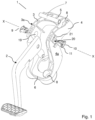
- Fig. 1 shows an exploded isometric view
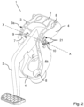
- Fig. 2 shows an isometric view in an assembled state of the mounting assembly 1.
- the mounting assembly 1 is arranged for pivotally supporting one or more control pedals 2 of a vehicle.
- the control pedal 2 may be a brake pedal, a clutch pedal or an accelerator pedal, or a group of two or more such pedals arranged around an axis of rotation X.
- the mounting assembly 1 comprises two walls 3, 4 arranged in parallel in relation to each other, and a first side 3a, 4a of the respective wall faces away from the other wall 3, 4.
- the first side 3a, 4a of each wall thereby can be seen as an outer wall in Fig. 1-2 .
- Opposite the respective first side 3a, 4a is a respective inner side of the wall 3, 4 facing the other wall 3, 4.
- the walls 3, 4 are rigidly joined together by means of an upper wall 5 and a lower wall 6.
- the walls 3, 4 are preferably generally perpendicularly arranged in relation to the upper wall 5 and lower wall 6, but the upper and lower walls 5, 6 may have other designs than in the figures.
- the upper wall 5 and the lower wall are provided with mounting holes 8 by means of which the mounting assembly 1 is fixed to the interior of the vehicle.
- the walls 3, 4 are also connected by means of a pivot shaft 7 which extend between the walls 3, 4.
- the pivot shaft 7 is preferably a cylindrical member, hollow or solid, but may also have any other configuration that is suitable for its use.
- At least a control pedal 2 is rigidly provided on the pivot shaft 7, such that the control pedal 2 may rotate in unison with the pivot shaft 7.
- an axis of rotation X is "arranged", around which the control pedal 2 and the pivot shaft 7 may rotate.
- the two locking means 9, 10 are arranged to pivotally retain the pivot shaft 7 in a using position between the walls 3, 4 by that the locking means 9, 10 are positioned on a respective end of the shaft 7 and are further positioned in a respective through opening 19, 20.
- the respective through opening 19, 20 is arranged to receive one locking means 9, 10 and the respective through opening 19, 20 has a shape complementary to the outer circumferential shape of the locking means 9, 10.
- the locking means 9, 10 is rotatable in the through opening 19, 20 from the mounting position to the locked using position.
- the locking means 9, 10 comprises a side wall shaped as a hollow tube and an inner diameter of the locking means 9, 10 of the hollow tube is larger than an outer diameter of the pivot shaft 7. This to allow the pivot shaft 7 to rotate within the locking means 9, 10 when the control pedal 2 is operated by a driver of the vehicle.
- the use position is a locked using position, in which the locking means pivotally retains the shaft 7 between the walls 3, 4, i.e. the shaft may be pivoted but is held in position between the walls 3, 4.
- the mounting assembly 1 is provided with a kind of a bayonet joint by that the locking means 9, 10 comprises at least one lock protrusion 11 provided on the locking means 9, 10 and, according to the preferred embodiment the walls 3, 4 are provided with at least one clamp 21, preferably two clamps 21, arranged at opposite sides of the respective through opening 19, 20.
- the lock protrusion 11, the clamp 21 are arranged to engage with each other when the locking means 9, 10 is in the locked using position (see Fig. 4a-b ), thereby preventing disengagement of the two locking means 9, 10 from the walls 3, 4, when in the locked using position.
- the bayonet joint further may comprise a rotation prevention protrusion in the form of a stop 25, which will be described in relation to Fig. 4a-b and Fig. 5a-b .
- Fig. 3a-c show a top view, a perspective view and a bottom view of the locking means 9, 10 according to the invention.
- the locking means 9, 10 has a cylindrical shaped casing, which in a cross section X is substantially tube-shaped.
- the function of the locking means 9, 10 is to hold the pivot shaft 7 and its control pedal 2 securely in place between the walls 3, 4, but also to minimize the play between the pivot shaft 7 and the walls 3, 4 and to act as a bearing for the pivot shaft 7, when a user applies a force to the control pedal 2 by means of a foot, and the pivot shaft 7 rotates around the axis of rotation X.
- the locking means 9, 10 is provided with the at least one lock protrusion 11.
- the locking means 9, 10 may be provided with two or more lock protrusions 11.
- the lock protrusion 11 extend in a radially direction, in relation to a center axis X of the hollow tube, from the outer surface 13 of the locking means 9, 10, and at a first axial end 9a, 10a of the locking means 9, 10.
- the lock protrusion 11 comprises at least one chamfered side edge 11a, which side edge 11a, 11b extend in a radially direction, in relation to a center axis X.
- the lock protrusion 11 comprises also a chamfered "back" side edge 11b, which is a back side seen in relation to the turning/twisting motion of the locking means 9, 10 counter-clockwise from the mounting position to the locked using position.
- the locking means 9, 10 further comprises one or more first axial securing protrusions 16a, 16b which protrudes in a radial direction from the outer surface 13 of the locking means, at a second axial end 9b, 10b of the locking means, which second end 9b, 10b is opposite the first end 9a, 10a.
- the locking means 9, 10 further comprises one or more resilient tongues 17a, 17b, which protrudes in a radial direction from the outer surface 13 of the locking means 9, 10 and the first axial securing protrusion 16a, 16b is preferably arranged at the resilient tongue 17a, 17b.
- the respective resilient tongue 17a, 17b further comprises a second axial securing protrusion 18a, 18b, which is arranged at the first axial end 9a, 10a of the locking means 9, 10.
- a second axial securing protrusion 18a, 18b By the first and second axial securing protrusions 17a, 17b, 18a, 18b, the locking means 9, 10 may be snapped into the trough hole 19, 20 and is thereby axially secured in both axial directions.
- the resilient tongue 17a, 17b aims to minimize the play between the locking means 9, 10 and the walls 3, 4 and to act as a bearing for the pivot shaft 7, as mentioned above.
- At least one of the locking means 9, 10 is provided with a grip 22 for enabling movement of the locking means 9, 10 from the mounting position to the locked using position.
- the grip 22 may for example be a flat-shaped groove or through opening, a cross-shaped groove or through opening, a hex grip for a hex key or the like.
- the grip 22 may also have any other suitable design.
- the lock protrusion 11 as well as the clamp 21 comprises preferably resilient material properties, to enable the lock protrusion 11 and/or the clamp 21 to deflect in an axial direction along the axis of rotation X and to achieve the locking action.
- the resilient properties of the locking means 9, 10 is provided by a resilient means (not shown) between the pivot shaft 7 and the at least one locking means 9, 10, so that the resilient means is pushed outwards in an axial direction of the pivot shaft 7 by the resilient means.
- the resilient means may be a coil spring.
- Fig. 4a-b show side views of a first side 4a of one sidewall 4 of the mounting assembly 1, when the locking means 10 is in a mounting position (to the left) and a in a locked using position (to the right). It is understood that the other sidewall 3 preferably has the same design, why only one of the walls is described here.
- Fig. 5a shows a zoomed view from above, relating to Fig. 4a-b , and shows an area near the side wall 4 in which one locking means 10 according to the invention is in a locked using position.
- Fig. 5b is a zoomed view of the stop 25 (stop-protrusion/rotation prevention protrusion) according to the invention.
- the wall 4 is provided with two clamps 21 for cooperation with the lock protrusion 11 of the locking means 10.
- the clamps 21 comprises first and second shanks 21a, 21c connected to each other by an elongate mid-section 21b.
- the elongate mid-section 21b is a bit thinner near the first shank 21a compared to near the second shank 21c, to provide an entrance opening for the lock protrusion 11.
- the first and second shanks 21a, 21c are fixedly attached to the first side 4a of the wall 4 and protrudes a first distance a from the first side 4a of the wall 4, such as a receiving space 26 for the lock protrusion 11 is formed between the first side 4a of the wall 4 and the locking clamp 21.
- a midpoint of the mid-section 21b of the locking clamp 21 is displaced a distance b relative the axis of rotation X of the pivot shaft 7 for allowing the at least one lock protrusion 11 to pass the first shank 21a of the clamp 21 and enter the receiving space 26, when the locking means 9, 10 is rotated into the through opening from the mounting position to the locked using position.
- the stop 25 is designed as a rotation prevention protrusion which prevents the lock protrusion 11 from leaving the receiving space 26, if for example the locking means 10 is accidently turned clockwise.
- the stop 25 is arranged in line with the mid-section 21b of the locking clamp 21 and protrudes from the first side 4a of the wall 4 in direction towards the mid-section 21b of the locking clamp 21. Further, the stop 25 is wedge-shaped with a tip 25a and an, in relation to the tip 25a opposite stop edge 25b.
- the stop 25 is arranged to, during the rotation of the locking means 10 in the through opening 20, from the mounting position to the locked using position, guide the at least one lock protrusion 11 towards the locked using position.
- the lock protrusion 11 is locked between the stop edge 25b of the stop 25 and the second shank 21c of the locking clamp 21.
- the pivot shaft 7, upon which the control pedal 2 is rigidly attached is introduced between the walls 3, 4.
- One free end of the pivot shaft 7 is introduced into one of the openings 19 of the walls 3, 4, where after the pivot shaft 7 is angled down such that the other free end of the pivot shaft 7 may be introduced to the other wall 3, 4.
- a first 9 of the two locking means 9, 10 is arranged onto a first end of the pivot shaft 7 and a second 10 of the two locking means is arranged onto a second end of the pivot shaft 7.
- each of the locking means 9, 10 first is oriented such that the lock protrusion 11 is oriented along the clamps 21, in the so called mounting position.
- the first axial securing protrusions 16a, 16b snaps behind the inside of the wall 4, i.e. engages with the edge of the through opening 19, 20.
- the second axial securing protrusions 18a, 18b abuts the first side 3a, 4a of the wall and the resilient tongues 17a, 17b makes sure the play between the locking means 9, 10 and the wall 3, 4 is minimized.
- the lock protrusion 11 as well as the clamp 21 comprises resilient material properties, the lock protrusion 11 and/or the clamp 21 deflects a bit in the axial direction and the chamfered side edge 11a facilitates a smooth sliding over the stop and may abut the clamp 21.
- the clamp 21 provides an extra security since it prevents the disengagement of the locking means 9, 10 from the wall by stopping an axial movement of the locking means 9, 10 in an outward direction.
- the mounting assembly 1 is wholly or partly manufactured of a polymeric material.
- the mounting assembly 1 may in another embodiment be wholly or partly be manufactured of any another material such as (not shown) a metallic material.
Landscapes
- Engineering & Computer Science (AREA)
- Transportation (AREA)
- Mechanical Engineering (AREA)
- Physics & Mathematics (AREA)
- General Physics & Mathematics (AREA)
- Automation & Control Theory (AREA)
- Chemical & Material Sciences (AREA)
- Combustion & Propulsion (AREA)
- Mechanical Control Devices (AREA)
- Snaps, Bayonet Connections, Set Pins, And Snap Rings (AREA)
Claims (13)
- Montageanordnung (1) für ein Steuerpedal eines Fahrzeugs, umfassend:- zwei Wände (3, 4) die parallel zueinander angeordnet sind, wobei jede Wand (3, 4) eine jeweilige Durchgangsöffnung (19, 20) umfasst,- eine Pedalachse (7), die sich zwischen den Wänden (3, 4) erstreckt, wobei die Pedalachse (7) mit ihrem jeweiligen Ende in die jeweilige Durchgangsöffnung (19, 20) eingesetzt ist,- mindestens ein Steuerpedal (2), das starr an der Pedalachse (7) vorgesehen ist, wobei das Steuerpedal (2) und die Pedalachse (7) um eine Rotationsachse (X) rotierbar sind,- zwei Verriegelungseinrichtungen (9, 10), die dazu angeordnet sind, die Pedalachse (7) drehbar zwischen den Wänden (3, 4) zu halten, indem die jeweilige Verriegelungseinrichtung (9, 10) am jeweiligen Ende der Pedalachse (7) positioniert und in die jeweilige Durchgangsöffnung (19, 20) der jeweiligen Wand (3, 4) eingesetzt ist, wobei die jeweilige Durchgangsöffnung (19, 20) dazu angeordnet ist, eine Verriegelungseinrichtung (9, 10) aufzunehmen, und die jeweilige Durchgangsöffnung (19, 20) eine Form aufweist, die zur Außenumfangsform der Verriegelungseinrichtung (9, 10) passt, und wobei die Verriegelungseinrichtung (9, 10) in der Durchgangsöffnung (19, 20) von einer Montageposition in eine Verriegelungsbetriebsposition rotierbar ist, wobei die Verriegelungseinrichtung (9, 10) ferner mindestens einen Verriegelungsvorsprung (11) umfasst, der sich von der Außenfläche (13) eines ersten axialen Endes (9a, 10a) der Verriegelungseinrichtung (9, 10) radial erstreckt, wobei die jeweilige Wand (3, 4) der Montageanordnung (1) auf einer von der anderen Wand abgewandten ersten Seite (3a, 4a) mindestens eine äußere Verriegelungsklammer (21) und mindestens einen Anschlag (25) umfasst, wobei der mindestens eine Verriegelungsvorsprung (11) der Verriegelungseinrichtung (9, 10) dazu angeordnet ist, in die Verriegelungsklammer (21) und den Anschlag (25) einzugreifen, wenn sich die Verriegelungseinrichtung (9, 10) in der Verriegelungsbetriebsposition befindet, wobei das Lösen der Verriegelungseinrichtung (9, 10) verhindert ist, dadurch gekennzeichnet, dass die Verriegelungsklammer (21) einen ersten und zweiten Schenkel (21a, 21c) umfasst, die über einen länglichen Mittelteil (21b) miteinander verbunden sind, wobei die Schenkel (21a, 21c) ferner fest an der ersten Seite (3a, 4a) der Wand (3, 4) befestigt sind und eine erste Entfernung (a) von der ersten Seite (3a, 4a) der Wand (3, 4) vorstehen, sodass ein Aufnahmeraum (26) für den Verriegelungsvorsprung (11) der Verriegelungseinrichtung (9, 10) zwischen der ersten Seite (3a, 4a) der Wand (3, 4) und der Verriegelungsklammer (21) ausgebildet wird.
- Montageanordnung nach Anspruch 1, wobei der Anschlag (25) mit dem Mittelteil (21b) der Verriegelungsklammer (21) ausgerichtet ist und von der ersten Seite (3a, 4a) der Wand (3, 4) in Richtung des Mittelteils (21b) der Verriegelungsklammer (21) vorsteht.
- Montageanordnung nach einem der vorstehenden Ansprüche, wobei der Anschlag (25) keilförmig ist, mit einer Spitze (25a) und einer der Spitze (25a) entgegengesetzten Anschlagkante (25b), wobei der Anschlag (25) dazu angeordnet ist, während der Rotation der Verriegelungseinrichtung (9, 10) in der Durchgangsöffnung (19, 20) von der Montageposition in die Verriegelungsbetriebsposition den mindestens einen Verriegelungsvorsprung (11) in die Verriegelungsbetriebsposition zu führen, in welcher der Verriegelungsvorsprung (11) zwischen der Anschlagkante (25b) des Anschlags (25) und dem zweiten Schenkel (21c) der Verriegelungsklammer (21) verriegelt ist.
- Montageanordnung nach einem der vorstehenden Ansprüche, wobei die Verriegelungsklammer (21) elastisch ist.
- Montageanordnung nach einem der vorstehenden Ansprüche, wobei der Verriegelungsvorsprung (11) mindestens eine gefaste Seitenkante (11a, 11b) umfasst, wobei sich die Seitenkante (11a, 11b) von der Außenfläche (13) der Verriegelungseinrichtung (9, 10) radial erstreckt.
- Montageanordnung nach einem der vorstehenden Ansprüche, wobei ein Mittelpunkt des Mittelteils (21b) der Verriegelungsklammer (21) eine Entfernung (b) zur Rotationsachse (X) der Pedalachse (7) versetzt ist, um zuzulassen, dass der mindestens eine Verriegelungsvorsprung (11) den ersten Schenkel (21a) der Klammer (21) passiert und in den Aufnahmeraum (26) eintritt, wenn die Verriegelungseinrichtung (9, 10) in die Durchgangsöffnung (19, 20) der Wand (3, 4) von der Montageposition in die Verriegelungsbetriebsposition rotiert wird.
- Montageanordnung nach einem der vorstehenden Ansprüche, wobei die Verriegelungseinrichtung (9, 10) ferner einen oder mehrere erste axiale Sicherungsvorsprünge (16a, 16b) umfasst, die in Radialrichtung von der Außenfläche (13) der Verriegelungseinrichtung vorstehen, wobei die ersten axialen Sicherungsvorsprünge (16a, 16b) an einem zweiten axialen Ende (9b, 10b) der Verriegelungseinrichtung angeordnet sind.
- Montageanordnung nach einem der vorstehenden Ansprüche, wobei die Verriegelungseinrichtung (9, 10) ferner eine oder mehrere elastische Federn (17a, 17b) umfasst, die in Radialrichtung von der Außenfläche (13) der Verriegelungseinrichtung (9, 10) vorstehen.
- Montageanordnung nach Anspruch 8, wobei die elastische Feder (17a, 17b) den ersten axialen Sicherungsvorsprung (16a, 16b) umfasst.
- Montageanordnung nach Anspruch 8 oder 9, wobei die elastische Feder (17a, 17b) einen zweiten axialen Sicherungsvorsprung (18a, 18b) umfasst, der am ersten axialen Ende (9a, 10a) der Verriegelungseinrichtung (9, 10) angeordnet ist.
- Montageanordnung nach einem der vorstehenden Ansprüche, wobei die mindestens eine Verriegelungseinrichtung (9, 10) mit einem Griff (22), um die Bewegung der Verriegelungseinrichtung (9, 10) von der Montageposition in die Verriegelungsbetriebsposition zu ermöglichen, versehen ist.
- Montageanordnung nach einem der vorstehenden Ansprüche, wobei der Mittelteil (21b) der Verriegelungsklammer (21) in der Nähe des ersten Schenkels (21a) schmaler ist als in der Nähe des zweiten Schenkels (21c).
- Montageanordnung nach einem der vorstehenden Ansprüche, wobei die Montageanordnung (1) aus einem Polymermaterial hergestellt ist.
Applications Claiming Priority (1)
| Application Number | Priority Date | Filing Date | Title |
|---|---|---|---|
| SE1951474A SE544128C2 (en) | 2019-12-17 | 2019-12-17 | Mounting assembly for a control pedal of a vehicle |
Publications (3)
| Publication Number | Publication Date |
|---|---|
| EP3855281A1 EP3855281A1 (de) | 2021-07-28 |
| EP3855281C0 EP3855281C0 (de) | 2024-11-13 |
| EP3855281B1 true EP3855281B1 (de) | 2024-11-13 |
Family
ID=73544073
Family Applications (1)
| Application Number | Title | Priority Date | Filing Date |
|---|---|---|---|
| EP20209262.3A Active EP3855281B1 (de) | 2019-12-17 | 2020-11-23 | Montageanordnung für ein steuerpedal eines kraftfahrzeugs |
Country Status (4)
| Country | Link |
|---|---|
| US (1) | US11048287B1 (de) |
| EP (1) | EP3855281B1 (de) |
| CN (1) | CN112977364B (de) |
| SE (1) | SE544128C2 (de) |
Family Cites Families (31)
| Publication number | Priority date | Publication date | Assignee | Title |
|---|---|---|---|---|
| DE3506860C2 (de) * | 1985-02-27 | 1987-05-14 | Mannesmann Kienzle GmbH, 7730 Villingen-Schwenningen | Einrichtung zur Verbindung von senkrecht zueinander verlaufenden Bauteilen |
| JP2653191B2 (ja) * | 1989-11-20 | 1997-09-10 | 日産自動車株式会社 | 自動車のペダル軸受け構造 |
| DE4230150A1 (de) * | 1991-09-19 | 1993-03-25 | Volkswagen Ag | Lagerbuchse aus kunststoff fuer einen fusshebel |
| US5588338A (en) | 1993-07-02 | 1996-12-31 | General Motors Corporation | Snap-in pedal with end caps |
| DE19743873C2 (de) * | 1997-10-04 | 2003-11-27 | Opel Adam Ag | Befestigungsanordnung mit einer vormontierten Baueineheit |
| FR2796012B1 (fr) * | 1999-07-05 | 2001-10-19 | Meyr | Dispositif de fixation dans une chape d'un axe de montage d'une pedale de vehicule |
| DE10039808A1 (de) * | 2000-08-16 | 2002-02-28 | Volkswagen Ag | Kunststoff-Gleitlagerbuchse und Pedalanordnung |
| GB0024603D0 (en) * | 2000-10-07 | 2000-11-22 | Dura Automotive Ltd | Collapsible pedal box |
| ITBO20010033A1 (it) * | 2001-01-25 | 2002-07-25 | Cisa Spa | Serratura a scrocco rotante e relativa bocchetta |
| DE10106710A1 (de) * | 2001-02-14 | 2002-08-22 | Siemens Ag | Pedal |
| DE10336799B4 (de) * | 2003-08-11 | 2015-05-07 | Volkswagen Ag | Fußhebelwerk mit Kunststoffbolzen |
| US20060053957A1 (en) * | 2004-07-08 | 2006-03-16 | Ewel David E | Electronic pedal assembly and method |
| JP2009169818A (ja) * | 2008-01-18 | 2009-07-30 | Daihatsu Motor Co Ltd | 車両におけるペダル装置 |
| GB2462818A (en) * | 2008-08-18 | 2010-02-24 | Senico Ltd | Apparatus and method for fixing to a laminated material |
| KR101114373B1 (ko) * | 2009-11-16 | 2012-02-14 | 기아자동차주식회사 | 브레이크 페달 스트로크 센서 |
| US20110314956A1 (en) * | 2010-06-23 | 2011-12-29 | Andrew Campbell | Assembly and Welding Method for Coupling a Rotor to the Shaft of a Pedal Assembly |
| ES2405939B1 (es) * | 2011-11-30 | 2014-08-05 | Batz, S.Coop. | Dispositivo de acoplamiento para al menos un pedal de vehículo motor |
| FR3008665B1 (fr) * | 2013-07-19 | 2015-07-31 | Renault Sa | Dispositif de montage d'une pedale dans un vehicule automobile |
| KR101491379B1 (ko) * | 2013-12-20 | 2015-02-11 | 현대자동차주식회사 | 차량용 클러치페달의 답력 저감장치 |
| SE538210C2 (sv) * | 2014-07-07 | 2016-04-05 | Cj Automotive Ab | Mechanical link system for pedal device |
| EP3015944B1 (de) * | 2014-10-28 | 2020-03-04 | Batz, S.Coop. | Pedal für Kraftfahrzeuge |
| JP6240060B2 (ja) * | 2014-12-18 | 2017-11-29 | トヨタ自動車株式会社 | 被保持部材の仮止め具および保持具 |
| SE538832C2 (sv) * | 2015-06-24 | 2016-12-20 | Cj Automotive Ab | Mounting assembly for a control pedal of a vehicle |
| CN108351665B (zh) * | 2015-06-24 | 2020-09-11 | Cj汽车制造公司 | 用于车辆的控制踏板的安装组件 |
| WO2016209154A1 (en) * | 2015-06-24 | 2016-12-29 | Cj Automotive Ab | Mounting assembly for a control pedal of a vehicle |
| US10296037B2 (en) * | 2015-09-18 | 2019-05-21 | Kongsberg Power Products Systems I, Inc. | Pedal assembly with identical first and second housing components |
| DE102017207417B4 (de) * | 2016-06-03 | 2022-08-11 | Ford Global Technologies, Llc | Vorrichtung zur Kraftsimulation an einem Betätigungselement eines Fahrzeugs und elektrisch betätigtes Kupplungssystem |
| KR102394830B1 (ko) * | 2017-06-28 | 2022-05-06 | 현대자동차주식회사 | 충격 분리 방식 페달 |
| US10173650B1 (en) * | 2017-11-29 | 2019-01-08 | Dura Operating, Llc | Pedal with snap-fit pivot bushing |
| US10960858B2 (en) * | 2018-04-23 | 2021-03-30 | Flex-N-Gate Advanced Product Development Llc. | Automotive pedal release system |
| CN208585228U (zh) * | 2018-06-15 | 2019-03-08 | 威马智慧出行科技(上海)有限公司 | 一种制动踏板结构和包含制动踏板结构的制动系统与车辆 |
-
2019
- 2019-12-17 SE SE1951474A patent/SE544128C2/en unknown
-
2020
- 2020-11-23 EP EP20209262.3A patent/EP3855281B1/de active Active
- 2020-12-07 US US17/113,325 patent/US11048287B1/en active Active
- 2020-12-11 CN CN202011456675.9A patent/CN112977364B/zh active Active
Also Published As
| Publication number | Publication date |
|---|---|
| US20210181780A1 (en) | 2021-06-17 |
| CN112977364B (zh) | 2024-03-08 |
| EP3855281C0 (de) | 2024-11-13 |
| SE544128C2 (en) | 2022-01-04 |
| EP3855281A1 (de) | 2021-07-28 |
| SE1951474A1 (en) | 2021-06-18 |
| US11048287B1 (en) | 2021-06-29 |
| CN112977364A (zh) | 2021-06-18 |
Similar Documents
| Publication | Publication Date | Title |
|---|---|---|
| JP5613525B2 (ja) | クリップ及び連結構造 | |
| US6949017B2 (en) | Hood mounting | |
| EP2308156B1 (de) | Schrittaktor | |
| US20020144885A1 (en) | Fitting structure for knobs | |
| US10036191B2 (en) | Vehicle door opening/closing apparatus | |
| US20150239371A1 (en) | Seat reclining device | |
| US8794860B1 (en) | Rotational connector device | |
| US6481550B2 (en) | Motor having clutch provided with stopper | |
| CN109899366A (zh) | 安装简单且可靠的连接器 | |
| US20010017496A1 (en) | Clutch having reduced noise level and motor including such clutch | |
| US20120066870A1 (en) | Quick-fit anchoring device for anchoring a sheath of a control cable to a mounting bracket | |
| JP4718494B2 (ja) | ケーブルドラムを収容するためのハウジング | |
| EP3855281B1 (de) | Montageanordnung für ein steuerpedal eines kraftfahrzeugs | |
| EP3314350B1 (de) | Montageanordnung für ein steuerpedal eines kraftfahrzeugs | |
| WO2016209154A1 (en) | Mounting assembly for a control pedal of a vehicle | |
| US6965180B2 (en) | Electric motor with self-adjusting bushing structure | |
| EP3060833B1 (de) | Magnetträgeranordnung | |
| CN101516683B (zh) | 转向柱模块 | |
| JP2007530879A (ja) | ネジボルトを備えた支持部材に固定するための装置 | |
| CN214837926U (zh) | 传动机构及轴承传动结构 | |
| WO2022114202A1 (ja) | 固定構造 | |
| JP2004162732A (ja) | トルク伝達具 | |
| US11630474B2 (en) | Systems and methods for a calibration knob | |
| US7619340B2 (en) | Drive unit with a rotationally fixed bearing element | |
| EP4606209A1 (de) | Scharnier für ein handwerkzeug, insbesondere für einen baumschneider |
Legal Events
| Date | Code | Title | Description |
|---|---|---|---|
| PUAI | Public reference made under article 153(3) epc to a published international application that has entered the european phase |
Free format text: ORIGINAL CODE: 0009012 |
|
| STAA | Information on the status of an ep patent application or granted ep patent |
Free format text: STATUS: THE APPLICATION HAS BEEN PUBLISHED |
|
| AK | Designated contracting states |
Kind code of ref document: A1 Designated state(s): AL AT BE BG CH CY CZ DE DK EE ES FI FR GB GR HR HU IE IS IT LI LT LU LV MC MK MT NL NO PL PT RO RS SE SI SK SM TR |
|
| STAA | Information on the status of an ep patent application or granted ep patent |
Free format text: STATUS: REQUEST FOR EXAMINATION WAS MADE |
|
| 17P | Request for examination filed |
Effective date: 20211222 |
|
| RBV | Designated contracting states (corrected) |
Designated state(s): AL AT BE BG CH CY CZ DE DK EE ES FI FR GB GR HR HU IE IS IT LI LT LU LV MC MK MT NL NO PL PT RO RS SE SI SK SM TR |
|
| RIC1 | Information provided on ipc code assigned before grant |
Ipc: B60T 7/06 20060101ALN20240307BHEP Ipc: G05G 1/44 20080401AFI20240307BHEP |
|
| RIC1 | Information provided on ipc code assigned before grant |
Ipc: B60T 7/06 20060101ALN20240308BHEP Ipc: G05G 1/44 20080401AFI20240308BHEP |
|
| GRAP | Despatch of communication of intention to grant a patent |
Free format text: ORIGINAL CODE: EPIDOSNIGR1 |
|
| STAA | Information on the status of an ep patent application or granted ep patent |
Free format text: STATUS: GRANT OF PATENT IS INTENDED |
|
| INTG | Intention to grant announced |
Effective date: 20240704 |
|
| GRAS | Grant fee paid |
Free format text: ORIGINAL CODE: EPIDOSNIGR3 |
|
| GRAA | (expected) grant |
Free format text: ORIGINAL CODE: 0009210 |
|
| STAA | Information on the status of an ep patent application or granted ep patent |
Free format text: STATUS: THE PATENT HAS BEEN GRANTED |
|
| AK | Designated contracting states |
Kind code of ref document: B1 Designated state(s): AL AT BE BG CH CY CZ DE DK EE ES FI FR GB GR HR HU IE IS IT LI LT LU LV MC MK MT NL NO PL PT RO RS SE SI SK SM TR |
|
| REG | Reference to a national code |
Ref country code: GB Ref legal event code: FG4D |
|
| REG | Reference to a national code |
Ref country code: CH Ref legal event code: EP |
|
| REG | Reference to a national code |
Ref country code: IE Ref legal event code: FG4D |
|
| REG | Reference to a national code |
Ref country code: DE Ref legal event code: R096 Ref document number: 602020041217 Country of ref document: DE |
|
| U01 | Request for unitary effect filed |
Effective date: 20241114 |
|
| U07 | Unitary effect registered |
Designated state(s): AT BE BG DE DK EE FI FR IT LT LU LV MT NL PT RO SE SI Effective date: 20241120 |
|
| U20 | Renewal fee for the european patent with unitary effect paid |
Year of fee payment: 5 Effective date: 20241114 |
|
| PG25 | Lapsed in a contracting state [announced via postgrant information from national office to epo] |
Ref country code: HR Free format text: LAPSE BECAUSE OF FAILURE TO SUBMIT A TRANSLATION OF THE DESCRIPTION OR TO PAY THE FEE WITHIN THE PRESCRIBED TIME-LIMIT Effective date: 20241113 Ref country code: IS Free format text: LAPSE BECAUSE OF FAILURE TO SUBMIT A TRANSLATION OF THE DESCRIPTION OR TO PAY THE FEE WITHIN THE PRESCRIBED TIME-LIMIT Effective date: 20250313 |
|
| PG25 | Lapsed in a contracting state [announced via postgrant information from national office to epo] |
Ref country code: ES Free format text: LAPSE BECAUSE OF FAILURE TO SUBMIT A TRANSLATION OF THE DESCRIPTION OR TO PAY THE FEE WITHIN THE PRESCRIBED TIME-LIMIT Effective date: 20241113 |
|
| PG25 | Lapsed in a contracting state [announced via postgrant information from national office to epo] |
Ref country code: NO Free format text: LAPSE BECAUSE OF FAILURE TO SUBMIT A TRANSLATION OF THE DESCRIPTION OR TO PAY THE FEE WITHIN THE PRESCRIBED TIME-LIMIT Effective date: 20250213 |
|
| PG25 | Lapsed in a contracting state [announced via postgrant information from national office to epo] |
Ref country code: GR Free format text: LAPSE BECAUSE OF FAILURE TO SUBMIT A TRANSLATION OF THE DESCRIPTION OR TO PAY THE FEE WITHIN THE PRESCRIBED TIME-LIMIT Effective date: 20250214 |
|
| PG25 | Lapsed in a contracting state [announced via postgrant information from national office to epo] |
Ref country code: PL Free format text: LAPSE BECAUSE OF FAILURE TO SUBMIT A TRANSLATION OF THE DESCRIPTION OR TO PAY THE FEE WITHIN THE PRESCRIBED TIME-LIMIT Effective date: 20241113 |
|
| PG25 | Lapsed in a contracting state [announced via postgrant information from national office to epo] |
Ref country code: RS Free format text: LAPSE BECAUSE OF FAILURE TO SUBMIT A TRANSLATION OF THE DESCRIPTION OR TO PAY THE FEE WITHIN THE PRESCRIBED TIME-LIMIT Effective date: 20250213 |
|
| REG | Reference to a national code |
Ref country code: CH Ref legal event code: PL |
|
| PG25 | Lapsed in a contracting state [announced via postgrant information from national office to epo] |
Ref country code: SM Free format text: LAPSE BECAUSE OF FAILURE TO SUBMIT A TRANSLATION OF THE DESCRIPTION OR TO PAY THE FEE WITHIN THE PRESCRIBED TIME-LIMIT Effective date: 20241113 |
|
| REG | Reference to a national code |
Ref country code: CH Ref legal event code: PL |
|
| PG25 | Lapsed in a contracting state [announced via postgrant information from national office to epo] |
Ref country code: CH Free format text: LAPSE BECAUSE OF NON-PAYMENT OF DUE FEES Effective date: 20241130 |
|
| PG25 | Lapsed in a contracting state [announced via postgrant information from national office to epo] |
Ref country code: SK Free format text: LAPSE BECAUSE OF FAILURE TO SUBMIT A TRANSLATION OF THE DESCRIPTION OR TO PAY THE FEE WITHIN THE PRESCRIBED TIME-LIMIT Effective date: 20241113 |
|
| PG25 | Lapsed in a contracting state [announced via postgrant information from national office to epo] |
Ref country code: CZ Free format text: LAPSE BECAUSE OF FAILURE TO SUBMIT A TRANSLATION OF THE DESCRIPTION OR TO PAY THE FEE WITHIN THE PRESCRIBED TIME-LIMIT Effective date: 20241113 |
|
| PG25 | Lapsed in a contracting state [announced via postgrant information from national office to epo] |
Ref country code: MC Free format text: LAPSE BECAUSE OF FAILURE TO SUBMIT A TRANSLATION OF THE DESCRIPTION OR TO PAY THE FEE WITHIN THE PRESCRIBED TIME-LIMIT Effective date: 20241113 |
|
| PLBE | No opposition filed within time limit |
Free format text: ORIGINAL CODE: 0009261 |
|
| STAA | Information on the status of an ep patent application or granted ep patent |
Free format text: STATUS: NO OPPOSITION FILED WITHIN TIME LIMIT |
|
| 26N | No opposition filed |
Effective date: 20250814 |
|
| PG25 | Lapsed in a contracting state [announced via postgrant information from national office to epo] |
Ref country code: IE Free format text: LAPSE BECAUSE OF NON-PAYMENT OF DUE FEES Effective date: 20241123 |
|
| GBPC | Gb: european patent ceased through non-payment of renewal fee |
Effective date: 20250213 |
|
| U20 | Renewal fee for the european patent with unitary effect paid |
Year of fee payment: 6 Effective date: 20251117 |
|
| PG25 | Lapsed in a contracting state [announced via postgrant information from national office to epo] |
Ref country code: GB Free format text: LAPSE BECAUSE OF NON-PAYMENT OF DUE FEES Effective date: 20250213 |
|
| PG25 | Lapsed in a contracting state [announced via postgrant information from national office to epo] |
Ref country code: HU Free format text: LAPSE BECAUSE OF FAILURE TO SUBMIT A TRANSLATION OF THE DESCRIPTION OR TO PAY THE FEE WITHIN THE PRESCRIBED TIME-LIMIT; INVALID AB INITIO Effective date: 20201123 |
|
| PG25 | Lapsed in a contracting state [announced via postgrant information from national office to epo] |
Ref country code: CY Free format text: LAPSE BECAUSE OF FAILURE TO SUBMIT A TRANSLATION OF THE DESCRIPTION OR TO PAY THE FEE WITHIN THE PRESCRIBED TIME-LIMIT; INVALID AB INITIO Effective date: 20201123 |