EP3855571A1 - Anschlussklemme und elektronisches gerät - Google Patents
Anschlussklemme und elektronisches gerät Download PDFInfo
- Publication number
- EP3855571A1 EP3855571A1 EP21150517.7A EP21150517A EP3855571A1 EP 3855571 A1 EP3855571 A1 EP 3855571A1 EP 21150517 A EP21150517 A EP 21150517A EP 3855571 A1 EP3855571 A1 EP 3855571A1
- Authority
- EP
- European Patent Office
- Prior art keywords
- actuating
- clamping
- actuating element
- clamping spring
- guide
- Prior art date
- Legal status (The legal status is an assumption and is not a legal conclusion. Google has not performed a legal analysis and makes no representation as to the accuracy of the status listed.)
- Granted
Links
Images


Classifications
-
- H—ELECTRICITY
- H01—ELECTRIC ELEMENTS
- H01R—ELECTRICALLY-CONDUCTIVE CONNECTIONS; STRUCTURAL ASSOCIATIONS OF A PLURALITY OF MUTUALLY-INSULATED ELECTRICAL CONNECTING ELEMENTS; COUPLING DEVICES; CURRENT COLLECTORS
- H01R13/00—Details of coupling devices of the kinds covered by groups H01R12/70 or H01R24/00 - H01R33/00
- H01R13/02—Contact members
- H01R13/10—Sockets for co-operation with pins or blades
- H01R13/11—Resilient sockets
-
- H—ELECTRICITY
- H01—ELECTRIC ELEMENTS
- H01R—ELECTRICALLY-CONDUCTIVE CONNECTIONS; STRUCTURAL ASSOCIATIONS OF A PLURALITY OF MUTUALLY-INSULATED ELECTRICAL CONNECTING ELEMENTS; COUPLING DEVICES; CURRENT COLLECTORS
- H01R9/00—Structural associations of a plurality of mutually-insulated electrical connecting elements, e.g. terminal strips or terminal blocks; Terminals or binding posts mounted upon a base or in a case; Bases therefor
- H01R9/22—Bases, e.g. strip, block, panel
- H01R9/24—Terminal blocks
- H01R9/2408—Modular blocks
-
- H—ELECTRICITY
- H01—ELECTRIC ELEMENTS
- H01R—ELECTRICALLY-CONDUCTIVE CONNECTIONS; STRUCTURAL ASSOCIATIONS OF A PLURALITY OF MUTUALLY-INSULATED ELECTRICAL CONNECTING ELEMENTS; COUPLING DEVICES; CURRENT COLLECTORS
- H01R4/00—Electrically-conductive connections between two or more conductive members in direct contact, i.e. touching one another; Means for effecting or maintaining such contact; Electrically-conductive connections having two or more spaced connecting locations for conductors and using contact members penetrating insulation
- H01R4/28—Clamped connections, spring connections
- H01R4/48—Clamped connections, spring connections utilising a spring, clip, or other resilient member
- H01R4/4809—Clamped connections, spring connections utilising a spring, clip, or other resilient member using a leaf spring to bias the conductor toward the busbar
- H01R4/4828—Spring-activating arrangements mounted on or integrally formed with the spring housing
- H01R4/4833—Sliding arrangements, e.g. sliding button
-
- H—ELECTRICITY
- H01—ELECTRIC ELEMENTS
- H01R—ELECTRICALLY-CONDUCTIVE CONNECTIONS; STRUCTURAL ASSOCIATIONS OF A PLURALITY OF MUTUALLY-INSULATED ELECTRICAL CONNECTING ELEMENTS; COUPLING DEVICES; CURRENT COLLECTORS
- H01R4/00—Electrically-conductive connections between two or more conductive members in direct contact, i.e. touching one another; Means for effecting or maintaining such contact; Electrically-conductive connections having two or more spaced connecting locations for conductors and using contact members penetrating insulation
- H01R4/28—Clamped connections, spring connections
- H01R4/48—Clamped connections, spring connections utilising a spring, clip, or other resilient member
- H01R4/4809—Clamped connections, spring connections utilising a spring, clip, or other resilient member using a leaf spring to bias the conductor toward the busbar
- H01R4/48185—Clamped connections, spring connections utilising a spring, clip, or other resilient member using a leaf spring to bias the conductor toward the busbar adapted for axial insertion of a wire end
- H01R4/4819—Clamped connections, spring connections utilising a spring, clip, or other resilient member using a leaf spring to bias the conductor toward the busbar adapted for axial insertion of a wire end the spring shape allowing insertion of the conductor end when the spring is unbiased
- H01R4/4821—Single-blade spring
-
- H—ELECTRICITY
- H01—ELECTRIC ELEMENTS
- H01R—ELECTRICALLY-CONDUCTIVE CONNECTIONS; STRUCTURAL ASSOCIATIONS OF A PLURALITY OF MUTUALLY-INSULATED ELECTRICAL CONNECTING ELEMENTS; COUPLING DEVICES; CURRENT COLLECTORS
- H01R4/00—Electrically-conductive connections between two or more conductive members in direct contact, i.e. touching one another; Means for effecting or maintaining such contact; Electrically-conductive connections having two or more spaced connecting locations for conductors and using contact members penetrating insulation
- H01R4/28—Clamped connections, spring connections
- H01R4/48—Clamped connections, spring connections utilising a spring, clip, or other resilient member
- H01R4/4809—Clamped connections, spring connections utilising a spring, clip, or other resilient member using a leaf spring to bias the conductor toward the busbar
- H01R4/484—Spring housing details
Definitions
- the invention relates to a connection terminal for connecting an electrical conductor, with a housing, a current bar arranged in the housing, a clamping spring arranged in the housing for clamping the conductor to be connected against the current bar in a conductor connection space formed between the current bar and the clamping spring, and an actuating element , which is displaceably mounted in the housing, wherein a clamping leg of the clamping spring can be actuated by means of the actuating element for transferring the clamping leg from a clamping position into an open position.
- the actuating element of such a connection terminal therefore serves, on the one hand, to actuate the clamping spring in order to clear the conductor connection space for inserting the conductor to be connected.
- the actuating element delimits the conductor connection space at least in sections. For both functions it is important that the actuating element reliably assumes its intended position both in the clamping position and in the open position.
- the actuating element is partially deformed in the open position by excessive force or is deflected from its intended position, an undesired gap can arise between the housing and the actuating element into which a conductor end of the conductor to be connected can be accidentally inserted so that it can in the clamping position, there may be no electrically conductive contact between the current bar and the electrical conductor to be connected.
- the invention is therefore based on the object of providing a connecting terminal and an electronic device which enable the clamping leg to be reliably actuated by the actuating element.
- a connection terminal for connecting an electrical conductor is specified, with a housing, a current bar arranged in the housing, a clamping spring arranged in the housing for clamping the conductor to be connected against the current bar in a conductor connection space formed between the current bar and the clamping spring, and an actuating element which is displaceably mounted in the housing, wherein a clamping leg of the clamping spring can be actuated by means of the actuating element in order to transfer the clamping leg from a clamping position into an open position.
- a guide element for supporting the actuation element and / or a guide element for supporting the clamping spring is provided below a section of the current bar against which the conductor is clamped by the clamping spring.
- the guide element for supporting the actuation element ensures that the actuation element is not deformed or deflected during the transfer from the clamping position to the open position and vice versa and remains reliably in contact with the clamping leg of the clamping spring.
- the guide element for supporting the clamping spring ensures that the clamping spring is not deformed or deflected, in particular during the actuation of the clamping spring by means of the actuating element, and reliably remains in the desired position within the housing.
- the connecting terminal can have the guide element for supporting the actuating element and the guide element for supporting the clamping spring. However, it is also possible for the connection terminal to have only one of the two guide elements.
- the actuating element delimits the conductor connection space at least in sections, in particular delimits it at least on two sides.
- the guide element is additionally used to support the actuating element ensures that no gaps formed by deformation or deflection of the actuating element can arise between the actuating element and the housing, which could lead to incorrect assembly of the electrical conductor to be connected.
- the guide element for supporting the actuating element and / or guide element for supporting the clamping spring can be an integral part of the housing. In this way, the respective guide element can be integrated into the shape of the housing in a cost-effective manner.
- the guide element for supporting the actuating element and / or the guide element for supporting the clamping spring and / or the housing have an electrically insulating plastic or can consist of an electrically insulating plastic.
- the guide element for supporting the actuating element and / or the guide element for supporting the clamping spring can, for example, be part of a side wall of the housing of the connecting terminal. Consequently, the guide element can be integrated compactly into the housing of the connection terminal.
- the guide element for supporting the actuating element and / or the guide element for supporting the clamping spring is provided as a separate component and has been connected to the housing of the connecting terminal.
- the guide element for supporting the actuating element and / or the guide element for supporting the clamping spring can be encapsulated with a plastic of the housing, so that a form-fitting connection between the guide element for supporting the actuating element and / or the guide element for supporting the clamping spring and the housing of the connecting terminal can be formed.
- the guide element for supporting the actuating element and / or the guide element for supporting the clamping spring is detachably connected to the housing of the connection terminal.
- the guide element for supporting the actuating element can be a web which engages around a section of the actuating element. Accordingly, deflection of the actuating element by the web can be prevented in a form-fitting manner.
- the guide element for supporting the clamping spring can also be a web which laterally supports a section of a retaining leg of the clamping spring.
- the guide element for supporting the clamping spring can prevent a lateral movement, in particular of the holding leg of the clamping spring, when the clamping leg of the clamping spring is transferred into the clamping position and into the open position. Even in the clamped state of a conductor, the guide element can be used to ensure that the clamping spring is seated securely, thereby preventing the clamping spring from tilting.
- the guide element for supporting the actuation element can be part of a linear guide which only enables a purely translational movement of the actuation element from a first position into a second position, so that the linear guide can deprive the actuation element of three rotational and two translational degrees of freedom .
- a linear guide can, for example, be predetermined in a purely form-fitting manner by a geometry of the housing of the connecting terminal in which the actuating element is received.
- the housing can have a shaft along which the actuating element can be moved, wherein the guide element for supporting the actuating element can serve as additional support against deflection or deformation of the actuating element.
- the guide element for supporting the actuation element can have a first guide surface which causes the actuation element to be supported against transverse displacement along a first direction.
- the guide element for supporting the actuation element can have a second guide surface which causes the actuation element to be supported against transverse displacement along a second direction which is different from the first direction.
- the first guide surface can be a flat surface.
- the second guide surface can be a flat surface.
- the first direction can be oriented orthogonally to the actuation direction of the actuation element.
- the second direction can be oriented orthogonally to the actuation direction of the actuation element.
- the first direction can be oriented orthogonally to the second direction.
- the actuating element can have at least one actuating arm, wherein the at least one actuating arm can delimit the conductor connection space transversely to an insertion direction of the conductor, the actuating arm with an actuating surface in the open position of the clamping spring being able to rest against the clamping leg of the clamping spring.
- the actuating arm with its clamping surface can also rest against the clamping leg of the clamping spring in the clamping position.
- the guide element for supporting the actuation element can be set up to prevent the actuation arm from being deflected transversely to the actuation direction of the actuation element and transversely to the insertion direction of the conductor to be connected. It can be provided that at least one guide surface of the guide element is provided to support the actuation element, along which the actuation element slides when the clamping leg is actuated, the surface normal of which can be oriented essentially perpendicular to the actuation direction and / or the insertion direction.
- At least one actuating arm can have at least one guide web, which can be arranged on a side of the actuating arm facing away from the conductor connection space and / or can slide along the guide element to support the actuating element when the actuating element is actuated.
- the guide web can be used for the defined contact of the actuating arm on the guide element.
- the actuating arm has two guide webs which are spaced apart from one another and which are designed to rest on the guide element for supporting the actuating element and / or a section of the housing.
- the guide webs can extend essentially parallel to one another.
- a further web can be arranged between the guide webs or several further webs can be arranged in order to achieve structural reinforcement of the actuating arm.
- At least one actuating arm can have a stop section for limiting a stroke of the actuating element.
- a sliding surface, along which a section of the clamping leg slides on the actuating arm when the clamping leg is actuated is provided on a recess of the actuating arm, which is at least partially delimited by the stop section.
- the stop section can be a hook-shaped end section of the actuating arm.
- the current bar can penetrate the actuating element, wherein the section of the current bar against which the conductor is clamped by the clamping spring can be arranged between the at least one actuating arm and a second actuating arm of the actuating element. In this way, the current bar can be compactly integrated into the housing of the connecting terminal together with the actuating element.
- the current bar can have recesses against which the actuating arms of the actuating element can rest, so that the current bar can also provide guidance for the actuating element.
- the actuating element can have an asymmetrical shape, the shape of the at least one actuating arm differing from the shape of the second actuating arm.
- the at least one actuating arm has a length measured along the actuating direction of the actuating element which is shorter than a length of the second actuating arm measured along the actuating direction of the actuating element.
- the second actuating arm can have a stop in order to predetermine a defined maximum stroke length, while the at least one actuating arm does not have such a stop and is accordingly shaped set back with respect to the second actuating arm.
- the at least one actuating arm has the aforementioned guide webs, for example, while the second actuating arm does not have such guide webs.
- the clamping leg of the clamping spring can have at least one skid which is in contact with the actuating element during the transfer of the clamping leg from the clamping position into the open position.
- the clamping spring can have a second skid which is in contact with the actuating element during the transfer of the clamping leg from the clamping position into the open position.
- Such a skid can be assigned an actuating surface or pressure surface of an actuating arm of the actuating element, along which the skid slides during the transfer of the clamping leg from the clamping position to the open position.
- the skid and / or the pressure surface can be designed in an arcuate manner, at least in sections, in order to promote smooth sliding.
- a skid can be a freely cantilevered end section of the clamping leg, which is arranged adjacent to or adjacent to a freely cantilevered contact section of the clamping leg, the contact section being intended to rest on the electrical conductor to be connected.
- connection terminal can be a series terminal which can be snapped onto a mounting rail.
- an electronic device is also specified, with one or more connecting terminals, the connecting terminals being designed and developed as described above.
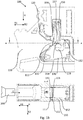
- FIG. 3 shows a connecting terminal 100 for connecting an electrical conductor 200.
- Such an electrical conductor 200 is shown schematically in the sectional illustration AA according to FIG Figure 1b indicated.
- the connection terminal 100 has a housing 110.
- a current bar 120 is arranged in the housing 110.
- a clamping spring 130 is also arranged in the housing 110. The clamping spring 130 serves to clamp the conductor 200 to be connected against the current bar 120.
- a conductor connection space 140 is formed between the current bar 120 and the clamping spring 130, in the area of which the conductor 200 to be connected is clamped against the current bar 120.
- the connecting terminal 100 has an actuating element 150 which is slidably mounted on the housing 110.
- the clamping spring 130 has a clamping leg 131.
- the actuating element 150 is designed to move the clamping leg 131 out of a clamping position ( Fig. 1a , Figure 1b ) to an open position ( Figure 1c , Fig. 1d ) to be transferred.
- the clamping leg 131 of the clamping spring 130 can be actuated by means of the actuating element 150 in order to transfer the clamping leg 131 from the clamping position into the open position.
- a guide element 111 for supporting the actuation element 150 is provided below a section 121 of the current bar 120, against which the conductor 200 is clamped by the clamping spring 130.
- the guide element 111 is an integral part of the housing 110.
- the guide element 111 can be seen as a web 111 which engages around a section 151 of the actuating element 150.
- the guide element 111 has a first guide surface 112, which supports the actuation element 150 against transverse displacement relative to the actuation direction H of the actuation element 150 along a first direction R1. That Guide element 111 has a second guide surface 113, which causes a support of the actuating element 150 against a transverse displacement to the actuating direction H along a second direction R2, which is different from the first direction R1. Accordingly, the web 111 counteracts a displacement of the actuating element 150 transversely to the actuating direction H in a form-fitting manner.
- the first direction R1 is oriented orthogonally to the actuation direction H of the actuation element 150.
- the second direction R2 is oriented orthogonally to the actuation direction H of the actuation element 150.
- the first direction R1 is oriented orthogonally to the second direction R2.
- the actuating element 150 has an actuating arm 152, the actuating arm 152 delimiting the conductor connection space 140 transversely to an insertion direction E of the conductor 200 and the actuating arm 152 with an actuating surface 154 in the open position of the clamping spring 130 resting on the clamping leg 131 of the clamping spring 130.
- the actuating arm 152 has a guide web 156 which is arranged on a side of the actuating arm 152 facing away from the conductor connection space 140 and which slides along the guide element 111 when the actuating element 150 is actuated.
- the actuating arm 152 has two further webs 157, 158 for stiffening and guiding the actuating element 150.
- the actuation element 150 has a second actuation arm 153 which has a stop section 159 for limiting a stroke of the actuation element 150 along the actuation direction H.
- the operating element 150 has an asymmetrical shape, the shape of the operating arm 152 being different from the shape of the second operating arm 153.
- the actuating arm 152 viewed along the actuating direction H, is shorter than the actuating arm 153, since the actuating arm 153 has the stop 159.
- the actuation element 150 has a further actuation surface 160 in the region of the second actuation arm 153, as in FIG Fig. 2 to recognize.
- the actuation surface 154 of the actuation arm 152 and the actuation surface 160 of the second actuation arm 153 are each curved in shape.
- a recess 161 is formed between the stop 159 and the actuating surface 160 of the second actuating arm 153.
- Fig. 3 shows an isolated illustration of the clamping spring 130.
- the clamping leg 131 of the clamping spring 130 has a first skid 132 which is in contact with the actuating element 150 during the transfer of the clamping leg 131 from the clamping position into the open position.
- the clamping leg 131 of the clamping spring 130 has a second skid 133 which is in contact with the actuating element 150 during the transfer of the clamping leg 131 from the clamping position to the open position.
- the first skid 132 is assigned the actuating surface 154 or pressure surface 154 of the actuating arm 152 of the actuating element 150, along which the skid 132 slides during the transfer of the clamping leg 131 from the clamping position to the open position and vice versa.
- the skid 132 and the pressure surface 154 are at least partially curved or curved in order to promote smooth sliding.
- the second skid 133 is assigned the actuating surface 160 or pressure surface 160 of the actuating arm 153 of the actuating element 150, along which the skid 133 slides during the transfer of the clamping leg 131 from the clamping position to the open position and vice versa.
- the skid 133 and the pressure surface 160 are at least partially curved or curved in order to promote smooth sliding.
- the runners 132, 133 are each freely projecting end sections of the clamping leg 131.
- the sliding runners 132, 133 are arranged adjacent to or adjacent to a freely projecting contact section 134 of the clamping leg 131, the contact section 134 being intended to rest on the electrical conductor 200 to be connected .
- the clamping spring 130 has recesses 137, 138 on a support leg 136 connected to the clamping leg 131 via an arched section 135 in order to create a free space for receiving the skids 132, 133 in the open position.
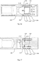
- Fig. 4 shows an isolated illustration of the current bar 120.
- the current bar 120 has recesses 122, 123, against which the actuating arms 152, 153 of the actuating element 150 can rest, so that the current bar 120 also provides guidance for the actuating element 150.
- the current bar 120 penetrates the actuating element 150, the section 121 of the current bar 120 being arranged between the actuating arm 152 and the second actuating arm 153 of the actuating element 50.
- Fig. 6 shows an isolated illustration of the housing 110.
- the housing 110 in the present case comprises an insulating plastic.
- the housing 110 has a shaft 114, along which the actuating element 150 can be moved.
- the shaft 114 has a recess 115 into which a web 162 of the actuating element 150 engages in order to predetermine a correctly positioned assembly.
- the guide element 111 and the shaft 114 form a linear guide for the actuation element 150, which only allows a purely translatory movement of the actuation element 152 along the actuation direction H from a first position ( Fig. 1a , Figure 1b ) in a second position ( Fig. 1a , Figure 1b ), so that the linear guide takes the actuating element 150 three rotational and two translational degrees of freedom.
- the guide element 111 serves in particular as an additional support against a deflection or deformation of the actuating arm 152 in order to prevent the actuating arm 152 from sliding off the skid 132.
- the housing 110 has a web 116 for receiving the clamping spring 130.
- the housing has a recess for receiving the current bar 120.
- the actuating element 150 is first removed from the circuit shown in FIG Fig. 1a position shown translationally along the actuation direction H into the in Figure 1c position shown emotional.
- the clamping spring 130 is compressed in this way, the clamping leg 131 being brought closer to the support leg 136.
- the actuating arm 152 is guided with its guide web 156 along the guide element 111 of the housing 110.
- the guide element 111 prevents the actuating arm 152 from being deflected in a direction R2 transverse to the actuating direction H and reliably remaining in engagement with the skid 132 of the clamping spring 130.
- the guide element 111 accordingly enables the actuation arm 152, viewed in the actuation direction H, to be guided in an area below the section 121 of the current bar 120.
- the conductor connection space 140 is released for insertion of the conductor 200 along the insertion direction E into the conductor connection space 140 and the conductor 200 can be moved between the clamping leg 131 and the current bar 120.
- the actuating element 150 is released and spring-loaded as a result of the tension of the clamping spring 130 is moved by the clamping leg 131 counter to the actuation direction H until the clamping leg 131 rests with its contact section 134 on the conductor 200 inserted into the conductor connection space 140 and the conductor 200 against the section 121 of the current bar 120 is pressed.
- the conductor 200 is clamped between the clamping spring 130 and the current bar 120, a spring force of the clamping spring 130 acting on the conductor 200 holding the conductor 200 in position.
- the actuating element 150 can be moved again in the actuating direction H in order to lift the contact section 134 of the clamping spring 130 from the conductor 200 and release it.
- the actuation element 150 can be moved against the spring force of the clamping spring 130, for example, manually with a tool, such as a Screwdriver or the like. Alternatively, it can be provided that the actuating element 150 is actuated by machine in order to enable automated assembly of the conductor 200.
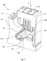
- FIG. 4 shows a further embodiment of a connection terminal 100 which, in addition to that in FIG Figures 1 to 6
- the embodiment of the connection terminal 100 shown has a guide element 162 for supporting the clamping spring 130.
- this guide element 162 By means of this guide element 162, in particular a lateral tilting or slipping of the clamping spring 130 out of the housing 110 can be prevented.
- the guide element 162 for supporting the clamping spring 130 like the guide element 111 for supporting the actuating element 150, is formed integrally and thus in one piece with the housing 110.
- the guide element 162 is formed on a side wall 164 of the housing 110.
- the guide element 162 thus forms an extension of the side wall 164.
- the guide element 111 for supporting the actuating element 150 and the guide element 162 for supporting the clamping spring 130 are thus both formed on the side wall 164 of the housing 110.
- the guide element 111 for supporting the actuating element 150 also forms an extension of the side wall 164.
- the guide element 162 is designed in the form of a web.
- the guide element 162 extends here opposite to the actuation direction H of the actuation element 150 in the direction of the conductor connection space 140.
- the guide element 162 for supporting the clamping spring 130 thus extends, starting from the side wall 164 of the housing 110 in the direction of the conductor connection space 140, transversely to the direction of extension of the guide element 111 for supporting the actuating element 150 starting from the side wall 164 of the housing.
- the guide element 111 for supporting the actuating element 150 and / or the guide element 162 for supporting the clamping spring 130 can each also be formed by two webs extending parallel to one another, not shown here, so that the actuating element 150 and / or the clamping spring 130 are supported on both sides can be done.
- the two webs of the guide element 111 and / or the two webs of the guide element 162 are then formed on two side walls 164 of the housing 110 that extend parallel to one another. Lateral tilting of the Actuating element 150 and / or the clamping spring can thus be prevented on two sides.
- the guide element 162 extends in the direction of the conductor connection space 140 in such a way that the guide element 162 laterally overlaps the retaining leg 163 of the clamping spring 130.
- the guide element 162 thus forms a lateral support surface for the holding leg 163 of the clamping spring 130.
- the guide element 162 is guided past a longitudinal side edge surface 165 of the holding leg 163.
- the guide element 162 for supporting the clamping spring 130 is formed below the section 121 of the current bar 120 against which the conductor 200 is clamped by the clamping spring 130.
Landscapes
- Details Of Connecting Devices For Male And Female Coupling (AREA)
- Connections Arranged To Contact A Plurality Of Conductors (AREA)
Abstract
Description
- Die Erfindung betrifft eine Anschlussklemme zum Anschließen eines elektrischen Leiters, mit einem Gehäuse, einem in dem Gehäuse angeordneten Strombalken, einer in dem Gehäuse angeordneten Klemmfeder zum Klemmen des anzuschließenden Leiters gegen den Strombalken in einem zwischen dem Strombalken und der Klemmfeder ausgebildeten Leiteranschlussraum, und einem Betätigungselement, welches verschiebbar dem Gehäuse gelagert ist, wobei ein Klemmschenkel der Klemmfeder zum Überführen des Klemmschenkels von einer Klemmstellung in eine Offenstellung mittels des Betätigungselements betätigbar ist.
- Das Betätigungselement einer solchen Anschlussklemme dient demnach einerseits dazu, die Klemmfeder zu betätigen, um den Leiteranschlussraum zum Einführen des anzuschließenden Leiters freizugeben. Andererseits kann vorgesehen sein, dass das Betätigungselement den Leiteranschlussraum zumindest abschnittsweise begrenzt. Für beide Funktionen ist es wichtig, dass das Betätigungselement sowohl in der Klemmstellung als auch in der Offenstellung seine vorgesehene Position zuverlässig einnimmt.
- Wird das Betätigungselement beispielsweise durch eine übermäßige Krafteinwirkung in der Offenstellung teilweise deformiert oder aus seiner vorgesehenen Position ausgelenkt, kann auf diese Weise ein nicht gewünschter Spalt zwischen dem Gehäuse und dem Betätigungselement entstehen, in den ein Leiterende des anzuschließenden Leiters versehentlich eingeführt werden kann, sodass es in der Klemmstellung gegebenenfalls nicht zu einer elektrisch leitenden Kontaktierung zwischen dem Strombalken und dem anzuschließenden elektrischen Leiter kommt.
- Weiter kann eine solche Deformation oder Auslenkung des Betätigungselements dazu führen, dass das Betätigungselement von dem Klemmschenkel der Klemmfeder abgleitet, sodass das Betätigungselement nicht mehr mit dem Klemmschenkel der Klemmfeder im Eingriff ist. Neben einer möglichen Beschädigung der Klemmfeder und/oder des Betätigungselements kann hier der Fall eintreten, dass der Klemmschenkel bereits vor dem Einführen des anzuschließenden elektrischen Leiters in die Klemmstellung zurückschnellt, sodass der Leiter nicht mehr in den Leiteranschlussraum eingeführt werden kann.
- Der Erfindung liegt daher die Aufgabe zu Grunde, eine Anschlussklemme und ein elektronisches Gerät zur Verfügung zu stellen, welche eine zuverlässige Betätigung des Klemmschenkels durch das Betätigungselement ermöglichen.
- Die Aufgabe wird erfindungsgemäß mit den Merkmalen der unabhängigen Ansprüche gelöst. Zweckmäßige Ausgestaltungen und vorteilhafte Weiterbildungen der Erfindung sind in den Unteransprüchen angegeben.
- Gemäß der Erfindung wird eine Anschlussklemme zum Anschließen eines elektrischen Leiters angegeben, mit einem Gehäuse, einem in dem Gehäuse angeordneten Strombalken, einer in dem Gehäuse angeordneten Klemmfeder zum Klemmen des anzuschließenden Leiters gegen den Strombalken in einem zwischen dem Strombalken und der Klemmfeder ausgebildeten Leiteranschlussraum, und einem Betätigungselement, welches verschiebbar in dem Gehäuse gelagert ist, wobei ein Klemmschenkel der Klemmfeder zum Überführen des Klemmschenkels von einer Klemmstellung in eine Offenstellung mittels des Betätigungselements betätigbar ist.
Entlang einer Betätigungsrichtung des Betätigungselements betrachtet ist, unterhalb eines Abschnitts des Strombalkens, gegen den der Leiter durch die Klemmfeder geklemmt wird, ein Führungselement zur Abstützung des Betätigungselements und/oder ein Führungselement zur Abstützung der Klemmfeder vorgesehen. - Das Führungselement zur Abstützung des Betätigungselements stellt sicher, dass das Betätigungselement während des Überführens aus der Klemmstellung in die Offenstellung, und umgekehrt, nicht deformiert oder ausgelenkt wird und zuverlässig mit dem Klemmschenkel der Klemmfeder in Kontakt bleibt. Das Führungselement zur Abstützung der Klemmfeder stellt sicher, dass die Klemmfeder insbesondere während des Betätigens der Klemmfeder mittels des Betätigungselements nicht deformiert oder ausgelenkt wird und zuverlässig in der gewünschten Position innerhalb des Gehäuses verbleibt. Die Anschlussklemme kann das Führungselement zur Abstützung des Betätigungselements und das Führungselement zur Abstützung der Klemmfeder aufweisen. Es ist aber auch möglich, dass die Anschlussklemme nur eines der beiden Führungselemente aufweist.
- Es kann vorgesehen sein, dass das Betätigungselement den Leiteranschlussraum zumindest abschnittsweise begrenzt, insbesondere zumindest zweiseitig begrenzt. In diesem Fall wird durch das Führungselement zur Abstützung des Betätigungselements zusätzlich sichergestellt, dass keine durch eine Deformation oder Auslenkung des Betätigungselements gebildeten Spalte zwischen dem Betätigungselement und dem Gehäuse entstehen können, die zu einer fehlerhaften Montage des anzuschließenden elektrischen Leiters führen könnten.
- Das Führungselement zur Abstützung des Betätigungselements und/oder Führungselement zur Abstützung der Klemmfeder kann integraler Bestandteil des Gehäuses sein. Auf diese Weise kann das jeweilige Führungselement kostengünstig in die Form des Gehäuses integriert werden.
- Beispielsweise kann es vorgesehen sein, dass das Führungselement zur Abstützung des Betätigungselements und/oder das Führungselement zur Abstützung der Klemmfeder und/oder das Gehäuse einen elektrisch isolierenden Kunststoff aufweisen oder aus einem elektrisch isolierenden Kunststoff bestehen können.
- Das Führungselement zur Abstützung des Betätigungselements und/oder das Führungselement zur Abstützung der Klemmfeder kann beispielsweise Teil einer Seitenwandung des Gehäuses der Anschlussklemme sein. Folglich kann das Führungselement kompakt in das Gehäuse der Anschlussklemme integriert sein.
- Alternativ kann es vorgesehen sein, dass das Führungselement zur Abstützung des Betätigungselements und/oder das Führungselement zur Abstützung der Klemmfeder als separates Bauteil bereitgestellt und mit dem Gehäuse der Anschlussklemme verbunden worden ist. Das Führungselement zur Abstützung des Betätigungselements und/oder das Führungselement zur Abstützung der Klemmfeder kann mit einem Kunststoff des Gehäuses umspritzt worden sein, sodass eine formschlüssige Verbindung zwischen dem Führungselement zur Abstützung des Betätigungselements und/oder das Führungselement zur Abstützung der Klemmfeder und dem Gehäuse der Anschlussklemme gebildet sein kann. Es kann vorgesehen sein, dass das Führungselement zur Abstützung des Betätigungselements und/oder das Führungselement zur Abstützung der Klemmfeder lösbar mit dem Gehäuse der Anschlussklemme verbunden ist.
- Das Führungselement zur Abstützung des Betätigungselements kann ein Steg sein, der einen Abschnitt des Betätigungselements umgreift. Demnach kann eine Auslenkung des Betätigungselements durch den Steg formschlüssig verhindert werden.
- Auch das Führungselement zur Abstützung der Klemmfeder kann ein Steg sein, der einen Abschnitt eines Halteschenkels der Klemmfeder seitlich abstützt. Das Führungselement zur Abstützung der Klemmfeder kann eine seitliche Bewegung insbesondere des Halteschenkels der Klemmfeder verhindern, wenn der Klemmschenkel der Klemmfeder in die Klemmstellung und in die Offenstellung überführt wird. Auch in dem klemmten Zustand eines Leiters kann mittels des Führungselements ein sicherer Sitz der Klemmfeder gewährleistet werden und damit ein Verkippen der Klemmfeder verhindert werden.
- Insbesondere kann es vorgesehen sein, dass das Führungselement zur Abstützung des Betätigungselements Teil einer Linearführung sein kann, die lediglich eine rein translatorische Bewegung des Betätigungselements aus einer ersten Position in eine zweite Position ermöglicht, sodass die Linearführung dem Betätigungselement drei rotatorische und zwei translatorische Freiheitsgrade nehmen kann. Eine solche Linearführung kann beispielsweise rein formschlüssig durch eine Geometrie des Gehäuses der Anschlussklemme vorgegeben werden, in dem das Betätigungselement aufgenommen ist. So kann das Gehäuse beispielsweise einen Schacht aufweisen, entlang dessen das Betätigungselement bewegbar ist, wobei das Führungselement zur Abstützung des Betätigungselements als zusätzliche Abstützung gegen eine Auslenkung oder Deformation des Betätigungselements dienen kann.
- Das Führungselement zur Abstützung des Betätigungselements kann eine erste Führungsfläche haben, die eine Abstützung des Betätigungselements gegen ein Querverschieben entlang einer ersten Richtung bewirkt. Das Führungselement zur Abstützung des Betätigungselements kann eine zweite Führungsfläche haben, die eine Abstützung des Betätigungselements gegen ein Querverschieben entlang einer zweiten Richtung bewirkt, die von der ersten Richtung verschieden ist. Wenn vorliegend von einem Querverschieben gesprochen wird, so handelt es sich dabei insbesondere um eine Verschiebung quer zu der Betätigungsrichtung des Betätigungselements, entlang derer das Betätigungselement eine translatorische Bewegung ausführt, um den Klemmschenkel aus seiner Klemmstellung in seine Offenstellung zu bewegen, und umgekehrt.
- Die erste Führungsfläche kann eine Planfläche sein. Die zweite Führungsfläche kann eine Planfläche sein.
- Die erste Richtung kann orthogonal zu der Betätigungsrichtung des Betätigungselements orientiert sein. Die zweite Richtung kann orthogonal zu der Betätigungsrichtung des Betätigungselements orientiert sein. Alternativ oder ergänzend kann die erste Richtung orthogonal zu der zweiten Richtung orientiert sein.
- Das Betätigungselement kann mindestens einen Betätigungsarm aufweisen, wobei der mindestens eine Betätigungsarm den Leiteranschlussraum quer zu einer Einführrichtung des Leiters begrenzen kann, wobei der Betätigungsarm mit einer Betätigungsfläche in der Offenstellung der Klemmfeder an dem Klemmschenkel der Klemmfeder anliegen kann. Je nach Einbaulage der Anschlussklemme kann vorgesehen sein, dass der Betätigungsarm mit seiner Klemmfläche auch in der Klemmstellung an dem Klemmschenkel der Klemmfeder anliegen kann.
- Das Führungselement zur Abstützung des Betätigungselements kann dazu eingerichtet sein, eine Auslenkung des Betätigungsarms quer zur Betätigungsrichtung des Betätigungselements und quer zur Einführrichtung des anzuschließenden Leiters zu verhindern. Es kann vorgesehen sein, dass mindestens eine Führungsfläche des Führungselements zur Abstützung des Betätigungselements vorgesehen ist, entlang derer das Betätigungselement beim Betätigen des Klemmschenkels abgleitet, deren Flächennormale im Wesentlichen senkrecht zur Betätigungsrichtung und oder zur Einführrichtung orientiert sein kann.
- Mindestens ein Betätigungsarm kann mindestens einen Führungssteg aufweisen, der auf einer dem Leiteranschlussraum abgewandten Seite des Betätigungsarms angeordnet sein kann und/oder beim Betätigen des Betätigungselements entlang dem Führungselement zur Abstützung des Betätigungselements abgleiten kann. Der Führungssteg kann zur definierten Anlage des Betätigungsarms an dem Führungselement dienen.
- Es kann vorgesehen sein, dass der Betätigungsarm zwei zueinander beabstandet die Führungsstege hat, die zur Anlage an dem Führungselement zur Abstützung des Betätigungselements und/oder einem Abschnitt des Gehäuses eingerichtet sind. Insbesondere können die Führungsstege im Wesentlichen parallel zueinander erstreckt sein. Zwischen den Führungsstegen kann ein weiterer Steg angeordnet sein bzw. können mehrere weitere Stege angeordnet sein, um eine strukturelle Aussteifung des Betätigungsarms zu erreichen.
- Mindestens ein Betätigungsarm kann einen Anschlagabschnitt zum Begrenzen eines Hubwegs des Betätigungselements haben. Insbesondere kann vorgesehen sein, dass eine Gleitfläche, entlang derer ein Abschnitt des Klemmschenkels beim Betätigen des Klemmschenkels an dem Betätigungsarm abgleitet, an einer Ausnehmung des Betätigungsarms vorgesehen ist, die zumindest abschnittsweise von dem Anschlagabschnitt begrenzt wird. Insbesondere kann der Anschlagabschnitt ein hakenförmiger Endabschnitt des Betätigungsarms sein.
- Der Strombalken kann das Betätigungselement durchdringen, wobei der Abschnitt des Strombalkens, gegen den der Leiter durch die Klemmfeder geklemmt wird, zwischen dem mindestens einen Betätigungsarm und einem zweiten Betätigungsarm des Betätigungselements angeordnet sein kann. Auf diese Weise kann der Strombalken zusammen mit dem Betätigungselement kompakt in das Gehäuse der Anschlussklemme integriert werden. Der Strombalken kann Aussparungen aufweisen, an denen die Betätigungsarme des Betätigungselements anliegen können, sodass auch der Strombalken eine Führung des Betätigungselements bereitstellen kann.
- Das Betätigungselement kann eine asymmetrische Form haben, wobei sich die Form des mindestens einen Betätigungsarms von der Form des zweiten Betätigungsarms unterscheidet.
- Es kann vorgesehen sein, dass der mindestens eine Betätigungsarm eine entlang der Betätigungsrichtung des Betätigungselements gemessene Länge aufweist, die geringer ist, als eine entlang der Betätigungsrichtung des Betätigungselements gemessene Länge des zweiten Betätigungsarms. Beispielsweise kann der zweite Betätigungsarm einen Anschlag haben, um eine definierte maximale Hublänge vorzugeben, während der mindestens eine Betätigungsarm keinen solchen Anschlag hat, und demnach gegenüber dem zweiten Betätigungsarm zurückversetzt geformt ist.
- Weiter kann es vorgesehen sein, dass der mindestens eine Betätigungsarm beispielsweise die vorgenannten Führungsstege aufweist, während der zweite Betätigungsarm keine solchen Führungsstege aufweist.
- Der Klemmschenkel der Klemmfeder kann mindestens eine Gleitkufe aufweisen, die mit dem Betätigungselement während des Überführens des Klemmschenkels von der Klemmstellung in die Offenstellung in Kontakt ist.
- Die Klemmfeder kann eine zweite Gleitkufe aufweisen, die mit dem Betätigungselement während des Überführens des Klemmschenkels von der Klemmstellung in die Offenstellung in Kontakt ist.
- Einer solchen Gleitkufe kann eine Betätigungsfläche bzw. Druckfläche eines Betätigungsarms des Betätigungselements zugeordnet sein, entlang derer die Gleitkufe während des Überführens des Klemmschenkel von der Klemmstellung in die Offenstellung abgleitet.
- Die Gleitkufe und/oder die Druckfläche können zumindest abschnittsweise bogenförmig ausgeführt sein, um ein ruckfreies Abgleiten zu begünstigen.
- Eine Gleitkufe kann ein frei auskragender Endabschnitt des Klemmschenkels sein, der angrenzend an bzw. benachbart zu einem frei auskragenden Kontaktabschnitt des Klemmschenkels angeordnet ist, wobei der Kontaktabschnitt zur Anlage an dem anzuschließenden elektrischen Leiter vorgesehen ist.
- Die Anschlussklemme kann eine Reihenklemme sein, welche auf einer Tragschiene aufgerastet werden kann.
- Gemäß der Erfindung wird zudem ein elektronisches Gerät angegeben, mit einer oder mehrere Anschlussklemmen, wobei die Anschlussklemmen wie vorstehend beschrieben, aus- und weitergebildet sind.
- Nachfolgend wird die Erfindung unter Bezugnahme auf die anliegenden Zeichnungen anhand bevorzugter Ausführungsformen näher erläutert.
- Es zeigen
- Fig. 1a
- eine schematische Darstellung einer Anschlussklemme gemäß der Erfindung in einer Klemmstellung in einer perspektivischen Ansicht,
- Fig. 1b
- eine schematische Darstellung der Anschlussklemme aus
Fig. 1a in einer Seitenansicht und in einem Schnitt entlang der Schnittebene A-A, - Fig. 1c
- eine schematische Darstellung der Anschlussklemme aus
Fig. 1a in einer Offenstellung in einer perspektivischen Ansicht, - Fig. 1d
- eine schematische Darstellung der Anschlussklemme aus
Fig. 1c in einer Seitenansicht, - Fig. 1e
- eine schematische Darstellung der Anschlussklemme aus
Fig. 1d in einem Schnitt entlang der Schnittebene B-B, - Fig. 1f
- eine schematische Darstellung der Anschlussklemme aus
Fig. 1d in einem Schnitt entlang der Schnittebene C-C, - Fig. 2
- eine schematische Darstellung eines Betätigungselements der Anschlussklemme aus
Fig. 1a in einer perspektivischen Ansicht, - Fig. 3
- eine schematische Darstellung der Klemmfeder der Anschlussklemme aus
Fig. 1a in einer perspektivischen Ansicht, - Fig. 4
- eine schematische Darstellung des Strombalkens der Anschlussklemme aus
Fig. 1a in einer perspektivischen Ansicht, - Fig. 5
- eine schematische Darstellung des Betätigungselements aus
Fig. 2 , der Klemmfeder ausFig. 3 und des Strombalkens ausFig. 4 in einer perspektivischen Ansicht, - Fig. 6
- eine schematische Darstellung eines Gehäuses der Anschlussklemme aus
Fig. 1a in einer perspektivischen Ansicht, und - Fig. 7
- eine schematische Darstellung einer Anschlussklemme gemäß einer weiteren Ausgestaltung der Erfindung.
-
Fig. 1a zeigt eine Anschlussklemme 100 zum Anschließen eines elektrischen Leiters 200. Ein solcher elektrischer Leiter 200 ist schematisch in der Schnittdarstellung A-A gemäßFig. 1b angedeutet. - Die Anschlussklemme 100 gemäß
Fig. 1a hat ein Gehäuse 110. In dem Gehäuse 110 ist ein Strombalken 120 angeordnet. In dem Gehäuse 110 ist zudem eine Klemmfeder 130 angeordnet. Die Klemmfeder 130 dient zum Klemmen des anzuschließenden Leiters 200 gegen den Strombalken 120. - Zwischen dem Strombalken 120 und der Klemmfeder 130 ist ein Leiteranschlussraum 140 gebildet, in dessen Bereich der anzuschließende Leiter 200 gegen den Strombalken 120 geklemmt wird.
- Die Anschlussklemme 100 hat ein Betätigungselement 150, das verschiebbar an dem Gehäuse 110 gelagert ist.
- Die Klemmfeder 130 hat einen Klemmschenkel 131. Das Betätigungselement 150 ist dazu eingerichtet, den Klemmschenkel 131 aus einer Klemmstellung (
Fig. 1a ,Fig. 1b ) in eine Offenstellung (Fig. 1c ,Fig. 1d ) zu überführen. Mit anderen Worten ist der Klemmschenkel 131 der Klemmfeder 130 zum Überführen des Klemmschenkels 131 von der Klemmstellung in die Offenstellung mittels des Betätigungselements 150 betätigbar. - Entlang einer Betätigungsrichtung H des Betätigungselements 150 betrachtet, ist, unterhalb eines Abschnitts 121 des Strombalkens 120, gegen den der Leiter 200 durch die Klemmfeder 130 geklemmt wird, ein Führungselement 111 zur Abstützung des Betätigungselements 150 vorgesehen ist.
- Das Führungselement 111 ist integraler Bestandteil des Gehäuses 110.
- Wie im Schnitt A-A der
Fig. 1b zu erkennen, ist das Führungselement 111 vorliegend ein Steg 111, der einen Abschnitt 151 des Betätigungselements 150 umgreift. - Das Führungselement 111 hat eine erste Führungsfläche 112, die eine Abstützung des Betätigungselements 150 gegen ein Querverschieben relativ zu der Betätigungsrichtung H des Betätigungselements 150 entlang einer ersten Richtung R1 bewirkt. Das Führungselement 111 hat eine zweite Führungsfläche 113, die eine Abstützung des Betätigungselements 150 gegen ein Querverschieben zu der Betätigungsrichtung H entlang einer zweiten Richtung R2 bewirkt, die von der ersten Richtung R1 verschieden ist. Demnach wirkt der Steg 111 einem Verschieben des Betätigungselements 150 quer zur Betätigungsrichtung H formschlüssig entgegen.
- Die erste Richtung R1 ist orthogonal zur Betätigungsrichtung H des Betätigungselements 150 orientiert. Die zweite Richtung R2 ist orthogonal zur Betätigungsrichtung H des Betätigungselements 150 orientiert. Die erste Richtung R1 ist orthogonal zu der zweiten Richtung R2 orientiert.
- Das Betätigungselement 150 weist einen Betätigungsarm 152 auf, wobei der Betätigungsarm 152 den Leiteranschlussraum 140 quer zu einer Einschubrichtung E des Leiters 200 begrenzt und wobei der Betätigungsarm 152 mit einer Betätigungsfläche 154 in der Offenstellung der Klemmfeder 130 an dem Klemmschenkel 131 der Klemmfeder 130 anliegt.
- Der Betätigungsarm 152 hat einen Führungssteg 156, der auf einer dem Leiteranschlussraum 140 abgewandten Seite des Betätigungsarms 152 angeordnet ist und beim Betätigen des Betätigungselements 150 entlang dem Führungselement 111 abgleitet. Der Betätigungsarm 152 hat zwei weitere Stege 157, 158 zum Aussteifen und Führen des Betätigungselements 150.
- Das Betätigungselement 150 hat einen zweiten Betätigungsarm 153, der einen Anschlagabschnitt 159 zum Begrenzen eines Hubwegs des Betätigungselements 150 entlang der Betätigungsrichtung H aufweist.
- Das Betätigungselement 150 hat eine asymmetrische Form, wobei sich die Form des Betätigungsarms 152 von der Form des zweiten Betätigungsarms 153 unterscheidet. Der Betätigungsarm 152 ist vorliegend entlang der Betätigungsrichtung H betrachtet kürzer als der Betätigungsarm 153, da der Betätigungsarm 153 den Anschlag 159 aufweist.
- Das Betätigungselement 150 hat im Bereich des zweiten Betätigungsarms 153 eine weitere Betätigungsfläche 160, wie in
Fig. 2 zu erkennen. Die Betätigungsfläche 154 des Betätigungsarms 152 und die Betätigungsfläche 160 des zweiten Betätigungsarms 153 sind jeweils gekrümmt geformt. Zwischen dem Anschlag 159 und der Betätigungsfläche 160 des zweiten Betätigungsarms 153 ist eine Ausnehmung 161 gebildet. -
Fig. 3 zeigt eine vereinzelte Darstellung der Klemmfeder 130. - Der Klemmschenkel 131 der Klemmfeder 130 hat eine erste Gleitkufe 132, die mit dem Betätigungselement 150 während des Überführens des Klemmschenkels 131 von der Klemmstellung in die Offenstellung in Kontakt ist.
- Der Klemmschenkel 131 der Klemmfeder 130 hat eine zweite Gleitkufe 133, die mit dem Betätigungselement 150 während des Überführens des Klemmschenkels 131 von der Klemmstellung in die Offenstellung in Kontakt ist.
- Der ersten Gleitkufe 132 ist die Betätigungsfläche 154 bzw. Druckfläche 154 des Betätigungsarms 152 des Betätigungselements 150 zugeordnet, entlang derer die Gleitkufe 132 während des Überführens des Klemmschenkels 131 von der Klemmstellung in die Offenstellung, und umgekehrt, abgleitet.
- Die Gleitkufe 132 und die Druckfläche 154 sind zumindest abschnittsweise bogenförmig bzw. gekrümmt ausgeführt, um ein ruckfreies Abgleiten zu begünstigen.
- Der zweiten Gleitkufe 133 ist die Betätigungsfläche 160 bzw. Druckfläche 160 des Betätigungsarms 153 des Betätigungselements 150 zugeordnet, entlang derer die Gleitkufe 133 während des Überführens des Klemmschenkels 131 von der Klemmstellung in die Offenstellung, und umgekehrt, abgleitet.
- Die Gleitkufe 133 und die Druckfläche 160 sind zumindest abschnittsweise bogenförmig bzw. gekrümmt ausgeführt, um ein ruckfreies Abgleiten zu begünstigen.
- Die Gleitkufen 132, 133 sind jeweils frei auskragende Endabschnitte des Klemmschenkels 131. Die Gleitkufen 132, 133 sind angrenzend an bzw. benachbart zu einem frei auskragenden Kontaktabschnitt 134 des Klemmschenkels 131 angeordnet, wobei der Kontaktabschnitt 134 zur Anlage an dem anzuschließenden elektrischen Leiter 200 vorgesehen ist.
- Die Klemmfeder 130 weist an einem über einen Bogenabschnitt 135 mit dem Klemmschenkel 131 verbundenen Stützschenkel 136 Aussparungen 137, 138 auf, um einen Freiraum zur Aufnahme der Gleitkufen 132, 133 in der Offenstellung zu schaffen.
-
Fig. 4 zeigt eine vereinzelte Darstellung des Strombalkens 120. Der Strombalken 120 hat Aussparungen 122, 123, an dem die Betätigungsarme 152, 153 des Betätigungselements 150 anliegen können, sodass auch der Strombalken 120 eine Führung des Betätigungselements 150 bereitstellt. - Wie
Fig. 5 zu entnehmen, durchdringt der Strombalken 120 das Betätigungselement 150, wobei der Abschnitt 121 des Strombalkens 120 zwischen dem Betätigungsarm 152 und dem zweiten Betätigungsarm 153 des Betätigungselements 50 angeordnet ist. -
Fig. 6 zeigt eine vereinzelte Darstellung des Gehäuses 110. Das Gehäuse 110 weist vorliegend einen isolierenden Kunststoff auf. - Das Gehäuse 110 hat einen Schacht 114, entlang dessen das Betätigungselement 150 bewegbar ist. Der Schacht 114 hat eine Aussparung 115, in die ein Steg 162 des Betätigungselements 150 eingreift, um eine lagerichtige Montage vorzugeben.
- Das Führungselement 111 und der Schacht 114 bilden eine Linearführung für das Betätigungselement 150, die lediglich eine rein translatorische Bewegung des Betätigungselements 152 entlang der Betätigungsrichtung H aus einer ersten Position (
Fig. 1a ,Fig. 1b ) in eine zweite Position zulässt (Fig. 1a ,Fig. 1b ), sodass die Linearführung dem Betätigungselement 150 drei rotatorische und zwei translatorische Freiheitsgrad nimmt. Das Führungselement 111 dient insbesondere als zusätzliche Abstützung gegen eine Auslenkung oder Deformation des Betätigungsarms 152, um ein Abgleiten Betätigungsarms 152 von der Gleitkufe 132 zu vermeiden. - Das Gehäuse 110 weit einen Steg 116 zur Aufnahme der Klemmfeder 130 auf. Das Gehäuse weist eine Aussparung zur Aufnahme des Strombalkens 120 auf.
- Zum Einklemmen eines Leiters 200 zwischen der Klemmfeder 130 und dem Strombalken 120 wird das Betätigungselement 150 zunächst aus der in
Fig. 1a gezeigten Position translatorisch entlang der Betätigungsrichtung H in die inFig. 1c gezeigte Position bewegt. Die Klemmfeder 130 wird auf diese Weise komprimiert, wobei der Klemmschenkel 131 dem Stützschenkel 136 angenähert wird. - Während dieser Hubbewegung gleiten die Gleitkufen 132, 133 entlang der Betätigungsflächen 154,160 der Betätigungsarme 152, 153 des Betätigungselements 150 ab.
- Der Betätigungsarm 152 wird dabei mit seinem Führungssteg 156 entlang des Führungselements 111 des Gehäuses 110 geführt. Das Führungselement 111 verhindert dabei, dass der Betätigungsarm 152 in einer Richtung R2 quer zur Betätigungsrichtung H ausgelenkt wird und zuverlässig mit der Gleitkufe 132 der Klemmfeder 130 im Eingriff bleibt. Das Führungselement 111 ermöglicht demnach eine Führung des Betätigungsarms 152 in der Betätigungsrichtung H betrachtet in einem Bereich unterhalb des Abschnitts 121 des Strombalkens 120.
- Sobald sich der Klemmschenkel 131 der Klemmfeder 130 in der in den
Figuren 1c und1d gezeigten Offenstellung befindet, ist der Leiteranschlussraum 140 zum Einführen des Leiters 200 entlang der Einschubrichtung E in den Leiteranschlussraum 140 freigegeben und der Leiter 200 kann zwischen den Klemmschenkel 131 und den Strombalken 120 bewegt werden. - Anschließend wird das Betätigungselement 150 losgelassen und federbeaufschlagt in Folge der Spannung der Klemmfeder 130 von dem Klemmschenkel 131 entgegen der Betätigungsrichtung H bewegt, bis der Klemmschenkel 131 mit seinem Kontaktabschnitt 134 an dem in den Leiteranschlussraum 140 eingeführten Leiter 200 anliegt und den Leiter 200 gegen den Abschnitt 121 des Strombalkens 120 presst. In diesem Zustand ist der Leiter 200 zwischen der Klemmfeder 130 und dem Strombalken 120 eingeklemmt, wobei eine auf den Leiter 200 wirkende Federkraft der Klemmfeder 130 den Leiter 200 in Position hält.
- Um den Leiter 200 wieder von der Anschlussklemme 100 zu lösen, kann das Betätigungselement 150 erneut in Betätigungsrichtung H bewegt werden, um den Kontaktabschnitt 134 der Klemmfeder 130 von dem Leiter 200 abzuheben und diesen freizugeben.
- Das Bewegen des Betätigungselements 150 entgegen der Federkraft der Klemmfeder 130 kann beispielsweise manuell mit einem Werkzeug erfolgen, wie einem Schraubendreher oder dergleichen. Alternativ kann vorgesehen sein, dass das Betätigungselement 150 maschinell betätigt wird, um eine automatisierte Montage des Leiters 200 zu ermöglichen.
-
Fig. 7 zeigt eine weitere Ausgestaltung einer Anschlussklemme 100, welche zusätzlich zu der inFig. 1 bis 6 gezeigten Ausgestaltung der Anschlussklemme 100 ein Führungselement 162 zur Abstützung der Klemmfeder 130 aufweist. Mittels diesem Führungselement 162 kann insbesondere ein seitliches Verkippen bzw. Verrutschen der Klemmfeder 130 aus dem Gehäuse 110 heraus verhindert werden. - Das Führungselement 162 zur Abstützung der Klemmfeder 130 ist hier, ebenfalls wie das Führungselement 111 zur Abstützung des Betätigungselements 150 integral und damit einstückig mit dem Gehäuse 110 ausgebildet. Das Führungselement 162 ist an einer Seitenwand 164 des Gehäuses 110 ausgebildet. Das Führungselement 162 bildet damit eine Verlängerung der Seitenwand 164 aus. Das Führungselement 111 zur Abstützung des Betätigungselements 150 und das Führungselement 162 zur Abstützung der Klemmfeder 130 sind damit beide an der Seitenwand 164 des Gehäuses 110 ausgebildet. Auch das Führungselement 111 zur Abstützung des Betätigungselements 150 bildet eine Verlängerung der Seitenwand 164 aus.
- Das Führungselement 162 ist in Form eines Stegs ausgebildet. Das Führungselement 162 erstreckt sich hier entgegengesetzt zu der Betätigungsrichtung H des Betätigungselements 150 in Richtung des Leiteranschlussraums 140. Das Führungselement 162 zur Abstützung der Klemmfeder 130 erstreckt sich damit ausgehend von der Seitenwand 164 des Gehäuses 110 in Richtung des Leiteranschlussraums 140 quer zu der Erstreckungsrichtung des Führungselements 111 zur Abstützung des Betätigungselements 150 ausgehend von der Seitenwand 164 des Gehäuses.
- Das Führungselement 111 zur Abstützung des Betätigungselements 150 und/oder das Führungselement 162 zur Abstützung der Klemmfeder 130 können jeweils auch durch zwei sich parallel zueinander erstreckende Stege ausgebildet sein, hier nicht gezeigt, so dass eine beidseitige Abstützung des Betätigungselements 150 und/oder der Klemmfeder 130 erfolgen kann. Die beiden Stege des Führungselements 111 und/oder die beiden Stege des Führungselements 162 sind dann an sich zwei parallel zueinander erstreckenden Seitenwänden 164 des Gehäuses 110 ausgebildet. Ein seitliches Verkippen des Betätigungselements 150 und/oder der Klemmfeder kann damit zu zwei Seiten verhindert werden.
- Das Führungselement 162 erstreckt sich derart in Richtung des Leiteranschlussraums 140, dass das Führungselement 162 den Halteschenkel 163 der Klemmfeder 130 seitlich überlappt. Damit bildet das Führungselement 162 eine seitliche Abstützfläche für den Halteschenkel 163 der Klemmfeder 130 aus. Das Führungselement 162 ist an einer Längsseitenkantenfläche 165 des Halteschenkels 163 vorbeigeführt.
- Das Führungselement 162 zur Abstützung der Klemmfeder 130 ist ebenso wie das Führungselement 111 entlang der Betätigungsrichtung H des Betätigungselements 150 betrachtet, unterhalb des Abschnitts 121 des Strombalkens 120, gegen den der Leiter 200 durch die Klemmfeder 130 geklemmt wird, ausgebildet.
-
- 100
- Anschlussklemme
- 110
- Gehäuse
- 111
- Führungselement
- 112
- erste Führungsfläche
- 113
- zweite Führungsfläche
- 114
- Schacht
- 115
- Aussparung
- 116
- Steg
- 120
- Strombalken
- 121
- Abschnitt
- 122
- Aussparung
- 123
- Aussparung
- 130
- Klemmfeder
- 131
- Klemmschenkel
- 132
- Gleitkufe
- 133
- Gleitkufe
- 134
- Kontaktabschnitt
- 135
- Bogenabschnitt
- 136
- Stützschenkel
- 137
- Aussparung
- 138
- Aussparung
- 140
- Leiteranschlussraum
- 150
- Betätigungselement
- 151
- Abschnitt
- 152
- Betätigungsarm
- 153
- Betätigungsarm
- 154
- Betätigungsfläche / Druckfläche
- 156
- Führungssteg
- 157
- Steg
- 158
- Steg
- 159
- Anschlag
- 160
- Betätigungsfläche / Druckfläche
- 161
- Ausnehmung
- 162
- Führungselement
- 163
- Halteschenkel
- 164
- Seitenwand
- 165
- Längsseitenkantenfläche
- 200
- Leiter
- E
- Einschubrichtung
- H
- Betätigungsrichtung
- R1
- Richtung
- R2
- Richtung
Claims (11)
- Anschlussklemme (100) zum Anschließen eines elektrischen Leiters (200), mit einem Gehäuse (110), einem in dem Gehäuse (110) angeordneten Strombalken (120), einer in dem Gehäuse (110) angeordneten Klemmfeder (130) zum Klemmen des anzuschließenden Leiters (200) gegen den Strombalken (120) in einem zwischen dem Strombalken (120) und der Klemmfeder (130) ausgebildeten Leiteranschlussraum (140), und einem Betätigungselement (150), welches verschiebbar in dem Gehäuse (110) gelagert ist, wobei ein Klemmschenkel (131) der Klemmfeder (130) zum Überführen des Klemmschenkels (131) von einer Klemmstellung in eine Offenstellung mittels des Betätigungselements (150) betätigbar ist, dadurch gekennzeichnet, dass, entlang einer Betätigungsrichtung (H) des Betätigungselements (150) betrachtet, unterhalb eines Abschnitts (121) des Strombalkens (120), gegen den der Leiter (200) durch die Klemmfeder (130) geklemmt wird, ein Führungselement (111) zur Abstützung des Betätigungselements (150) vorgesehen ist und/oder ein Führungselement (162) zur Abstützung der Klemmfeder (130) vorgesehen ist.
- Anschlussklemme (100) nach Anspruch 1, dadurch gekennzeichnet, dass das Führungselement (111) zur Abstützung des Betätigungselements (150) und/oder das Führungselement (162) zur Abstützung der Klemmfeder (130) integraler Bestandteil des Gehäuses (110) ist.
- Anschlussklemme (100) nach Anspruch 1 oder 2, dadurch gekennzeichnet, dass das Führungselement (111) zur Abstützung des Betätigungselements (150) ein Steg ist, der einen Abschnitt (151) des Betätigungselements (151) umgreift, und/oder dass das Führungselement (162) zur Abstützung der Klemmfeder (130) ein Steg ist, der einen Abschnitt eines Halteschenkels (163) der Klemmfeder (130) seitlich abstützt.
- Anschlussklemme (100) nach einem der Ansprüche 1 bis 3, dadurch gekennzeichnet, dass das Führungselement (111) zur Abstützung des Betätigungselements (150) eine erste Führungsfläche (112) hat, die eine Abstützung des Betätigungselements (150) gegen ein Querverschieben entlang einer ersten Richtung (R1) bewirkt und das Führungselement (111) zur Abstützung des Betätigungselements (150) eine zweite Führungsfläche (113) hat, die eine Abstützung des Betätigungselements (150) gegen ein Querverschieben entlang einer zweiten Richtung (R2) bewirkt, die von der ersten Richtung (R1) verschieden ist.
- Anschlussklemme (100) nach einem der Ansprüche 4, dadurch gekennzeichnet, dass die erste Richtung (R1) orthogonal zu der Betätigungsrichtung (H) des Betätigungselements (150) orientiert ist und die zweite Richtung (R2) orthogonal zu der Betätigungsrichtung (H) des Betätigungselements (150) orientiert ist und/oder dass die erste Richtung (R1) orthogonal zu der zweiten Richtung (R2) orientiert ist.
- Anschlussklemme (100) nach einem der Ansprüche 1 bis 5, dadurch gekennzeichnet, dass das Betätigungselement (150) mindestens einen Betätigungsarm (152, 153) aufweist, wobei der mindestens eine Betätigungsarm den Leiteranschlussraum (140) quer zu einer Einführrichtung (E) des Leiters (200) begrenzt, wobei der Betätigungsarm (152, 153) mit einer Betätigungsfläche (154, 160) in der Offenstellung der Klemmfeder (130) an dem Klemmschenkel (131) der Klemmfeder (130) anliegt.
- Anschlussklemme nach Anspruch 6, dadurch gekennzeichnet, dass mindestens ein Betätigungsarm (152) mindestens einen Führungssteg (156) aufweist, der auf einer dem Leiteranschlussraum (140) abgewandten Seite des Betätigungsarms (152) angeordnet ist und/oder beim Betätigen des Betätigungselements (150) entlang dem Führungselement (111) zur Abstützung des Betätigungselements (150) abgleitet.
- Anschlussklemme nach Anspruch 6 oder Anspruch 7, dadurch gekennzeichnet, dass mindestens ein Betätigungsarm (153) einen Anschlagabschnitt (159) zum Begrenzen eines Hubwegs des Betätigungselements (150) hat.
- Anschlussklemme nach einem der Ansprüche 6 bis 8, dadurch gekennzeichnet, dass der Strombalken (120) das Betätigungselement (150) durchdringt, wobei der Abschnitt (121) des Strombalkens (120) zwischen dem mindestens einen Betätigungsarm (152) und einem zweiten Betätigungsarm (153) des Betätigungselements (150) angeordnet ist.
- Anschlussklemme nach Anspruch 9, dadurch gekennzeichnet, dass das Betätigungselement (150) eine asymmetrische Form hat, wobei sich die Form des mindestens einen Betätigungsarms (152) von der Form des zweiten Betätigungsarms (153) unterscheidet.
- Elektronisches Gerät, mit einer oder mehreren Anschlussklemmen (100), die nach einem der Ansprüche 1 bis 10 ausgebildet sind.
Applications Claiming Priority (1)
| Application Number | Priority Date | Filing Date | Title |
|---|---|---|---|
| DE102020101653.0A DE102020101653A1 (de) | 2020-01-24 | 2020-01-24 | Anschlussklemme und elektronisches Gerät |
Publications (2)
| Publication Number | Publication Date |
|---|---|
| EP3855571A1 true EP3855571A1 (de) | 2021-07-28 |
| EP3855571B1 EP3855571B1 (de) | 2023-11-08 |
Family
ID=74105903
Family Applications (1)
| Application Number | Title | Priority Date | Filing Date |
|---|---|---|---|
| EP21150517.7A Active EP3855571B1 (de) | 2020-01-24 | 2021-01-07 | Anschlussklemme und elektronisches gerät |
Country Status (3)
| Country | Link |
|---|---|
| EP (1) | EP3855571B1 (de) |
| CN (1) | CN113178723B (de) |
| DE (1) | DE102020101653A1 (de) |
Cited By (1)
| Publication number | Priority date | Publication date | Assignee | Title |
|---|---|---|---|---|
| WO2023213511A1 (de) * | 2022-05-06 | 2023-11-09 | Weidmüller Interface GmbH & Co. KG | Anschlussvorrichtung, die als federkraftklemme zum anschluss eines leiters ausgelegt ist |
Families Citing this family (3)
| Publication number | Priority date | Publication date | Assignee | Title |
|---|---|---|---|---|
| DE102021122816A1 (de) * | 2021-09-03 | 2023-03-09 | Phoenix Contact Gmbh & Co. Kg | Anschlussanordnung, Anschlussklemme und elektronisches Gerät |
| DE102021129010A1 (de) | 2021-11-08 | 2023-05-11 | Harting Electric Stiftung & Co. Kg | Kontaktträgereinrichtung, Anschlussvorrichtung, Betätiger, Steckverbindereinsatz und Montageverfahren sowie Kabelanschlusssystem |
| DE102023134934A1 (de) * | 2023-12-13 | 2025-06-18 | Phoenix Contact Gmbh & Co. Kg | Anschlussanordnung und Anschlussklemme |
Citations (5)
| Publication number | Priority date | Publication date | Assignee | Title |
|---|---|---|---|---|
| DE102006016364A1 (de) * | 2006-04-05 | 2007-10-18 | Mc Technology Gmbh | Klemmenblock zum Anschließen von elektrischen Leitern |
| DE102010025930A1 (de) * | 2010-07-02 | 2012-01-05 | Phoenix Contact Gmbh & Co. Kg | Anschlussklemme |
| CN202564566U (zh) * | 2012-04-28 | 2012-11-28 | 东莞市长河电子有限公司 | 免螺丝压扣式接线连接器 |
| US20180166802A1 (en) * | 2016-12-13 | 2018-06-14 | Excel Cell Electronic Co., Ltd. | Terminal block |
| WO2020182639A1 (de) * | 2019-03-13 | 2020-09-17 | Phoenix Contact Gmbh & Co. Kg | Anschlussklemme |
Family Cites Families (5)
| Publication number | Priority date | Publication date | Assignee | Title |
|---|---|---|---|---|
| JP3159973B1 (ja) | 2000-01-21 | 2001-04-23 | 株式会社八光電機製作所 | 端子・ばね一体型のクランプ端子 |
| DE102007050683B4 (de) | 2007-10-22 | 2009-09-03 | Wago Verwaltungsgesellschaft Mbh | Leiteranschlussklemme |
| DE202008014469U1 (de) * | 2008-10-31 | 2010-03-18 | Weidmüller Interface GmbH & Co. KG | Anschlussklemme zum Anschluss von Leiterenden |
| DE102017106720A1 (de) * | 2017-03-29 | 2018-10-04 | Phoenix Contact Gmbh & Co. Kg | Kompakte Leiteranschlussklemme |
| DE102019106353B4 (de) | 2019-03-13 | 2023-05-25 | Phoenix Contact Gmbh & Co. Kg | Leiteranschlussklemme mit einem Betätigungselement mit angepasster Druckfläche |
-
2020
- 2020-01-24 DE DE102020101653.0A patent/DE102020101653A1/de active Pending
-
2021
- 2021-01-07 EP EP21150517.7A patent/EP3855571B1/de active Active
- 2021-01-22 CN CN202110087644.9A patent/CN113178723B/zh active Active
Patent Citations (5)
| Publication number | Priority date | Publication date | Assignee | Title |
|---|---|---|---|---|
| DE102006016364A1 (de) * | 2006-04-05 | 2007-10-18 | Mc Technology Gmbh | Klemmenblock zum Anschließen von elektrischen Leitern |
| DE102010025930A1 (de) * | 2010-07-02 | 2012-01-05 | Phoenix Contact Gmbh & Co. Kg | Anschlussklemme |
| CN202564566U (zh) * | 2012-04-28 | 2012-11-28 | 东莞市长河电子有限公司 | 免螺丝压扣式接线连接器 |
| US20180166802A1 (en) * | 2016-12-13 | 2018-06-14 | Excel Cell Electronic Co., Ltd. | Terminal block |
| WO2020182639A1 (de) * | 2019-03-13 | 2020-09-17 | Phoenix Contact Gmbh & Co. Kg | Anschlussklemme |
Cited By (1)
| Publication number | Priority date | Publication date | Assignee | Title |
|---|---|---|---|---|
| WO2023213511A1 (de) * | 2022-05-06 | 2023-11-09 | Weidmüller Interface GmbH & Co. KG | Anschlussvorrichtung, die als federkraftklemme zum anschluss eines leiters ausgelegt ist |
Also Published As
| Publication number | Publication date |
|---|---|
| CN113178723B (zh) | 2023-06-20 |
| EP3855571B1 (de) | 2023-11-08 |
| DE102020101653A1 (de) | 2021-07-29 |
| CN113178723A (zh) | 2021-07-27 |
Similar Documents
| Publication | Publication Date | Title |
|---|---|---|
| EP3855571B1 (de) | Anschlussklemme und elektronisches gerät | |
| EP3298659B1 (de) | Leiteranschlussklemme | |
| EP2946442B1 (de) | Anschlussklemme | |
| EP2786447B1 (de) | Anschlussklemme mit einer stegförmigen leiterführung | |
| DE2338056B2 (de) | Elektrische Anschlußklemme | |
| DE2204924A1 (de) | Elektrische Verbinderanordnung | |
| DE9217310U1 (de) | Elektrische Verbindung mit Mitteln zum Festlegen von Kontakten | |
| WO2011009837A1 (de) | Anschlussvorrichtung und rangierklemme | |
| EP3843221B1 (de) | Halterahmen für einen steckverbinder | |
| EP3490075A1 (de) | Set aus steckverbinder und halteelement sowie steckverbinder und halteelement hierzu | |
| DE9102716U1 (de) | Vorrichtung zum Verbinden von einer Vielzahl von zumindest teilweise mit einer Isolation versehenen Leitern mit elektrischen Kontakten | |
| DE102007039307A1 (de) | Steckverbinder | |
| DE102019120306B4 (de) | Leiteranschlussklemme zum Anschluss wenigstens eines elektrischen Leiters | |
| DE19838432C1 (de) | Installationsgerät zur Montage an einer Hutschiene | |
| DE2541922B2 (de) | Verriegelbarer Drucktastenschalter | |
| EP3501064A1 (de) | Anschlusselement | |
| DE202015104145U1 (de) | Klemme | |
| EP0451726A1 (de) | Schnellbefestigung für ein elektrisches Installationsgerät | |
| DE19530844B4 (de) | Elektrischer Steckverbinder mit Betätigungsschieber | |
| DE19546504C2 (de) | Schaltanordnung mit wenigstens zwei flachliegenden, elektrischen Leitsteifen | |
| DE202022105595U1 (de) | Leiteranschlussklemme und Betätigungselement | |
| EP1936754A2 (de) | Steckverbinder mit einem Gehäuse mit einem Betätigungselement und einem Rastmittel | |
| EP1178582B1 (de) | Installationsgerät mit Riegel zur Montage an einer Hutschiene | |
| EP0197376B1 (de) | Sockel für Bauelement | |
| DE202024102562U1 (de) | Federkraftklemmanschluss und Leiteranschlussklemme |
Legal Events
| Date | Code | Title | Description |
|---|---|---|---|
| PUAI | Public reference made under article 153(3) epc to a published international application that has entered the european phase |
Free format text: ORIGINAL CODE: 0009012 |
|
| STAA | Information on the status of an ep patent application or granted ep patent |
Free format text: STATUS: THE APPLICATION HAS BEEN PUBLISHED |
|
| AK | Designated contracting states |
Kind code of ref document: A1 Designated state(s): AL AT BE BG CH CY CZ DE DK EE ES FI FR GB GR HR HU IE IS IT LI LT LU LV MC MK MT NL NO PL PT RO RS SE SI SK SM TR |
|
| STAA | Information on the status of an ep patent application or granted ep patent |
Free format text: STATUS: REQUEST FOR EXAMINATION WAS MADE |
|
| 17P | Request for examination filed |
Effective date: 20211210 |
|
| RBV | Designated contracting states (corrected) |
Designated state(s): AL AT BE BG CH CY CZ DE DK EE ES FI FR GB GR HR HU IE IS IT LI LT LU LV MC MK MT NL NO PL PT RO RS SE SI SK SM TR |
|
| GRAP | Despatch of communication of intention to grant a patent |
Free format text: ORIGINAL CODE: EPIDOSNIGR1 |
|
| STAA | Information on the status of an ep patent application or granted ep patent |
Free format text: STATUS: GRANT OF PATENT IS INTENDED |
|
| P01 | Opt-out of the competence of the unified patent court (upc) registered |
Effective date: 20230512 |
|
| INTG | Intention to grant announced |
Effective date: 20230601 |
|
| GRAS | Grant fee paid |
Free format text: ORIGINAL CODE: EPIDOSNIGR3 |
|
| GRAA | (expected) grant |
Free format text: ORIGINAL CODE: 0009210 |
|
| STAA | Information on the status of an ep patent application or granted ep patent |
Free format text: STATUS: THE PATENT HAS BEEN GRANTED |
|
| AK | Designated contracting states |
Kind code of ref document: B1 Designated state(s): AL AT BE BG CH CY CZ DE DK EE ES FI FR GB GR HR HU IE IS IT LI LT LU LV MC MK MT NL NO PL PT RO RS SE SI SK SM TR |
|
| REG | Reference to a national code |
Ref country code: GB Ref legal event code: FG4D Free format text: NOT ENGLISH |
|
| REG | Reference to a national code |
Ref country code: CH Ref legal event code: EP |
|
| REG | Reference to a national code |
Ref country code: DE Ref legal event code: R096 Ref document number: 502021001884 Country of ref document: DE |
|
| REG | Reference to a national code |
Ref country code: IE Ref legal event code: FG4D Free format text: LANGUAGE OF EP DOCUMENT: GERMAN |
|
| REG | Reference to a national code |
Ref country code: LT Ref legal event code: MG9D |
|
| REG | Reference to a national code |
Ref country code: NL Ref legal event code: MP Effective date: 20231108 |
|
| PG25 | Lapsed in a contracting state [announced via postgrant information from national office to epo] |
Ref country code: GR Free format text: LAPSE BECAUSE OF FAILURE TO SUBMIT A TRANSLATION OF THE DESCRIPTION OR TO PAY THE FEE WITHIN THE PRESCRIBED TIME-LIMIT Effective date: 20240209 |
|
| PG25 | Lapsed in a contracting state [announced via postgrant information from national office to epo] |
Ref country code: IS Free format text: LAPSE BECAUSE OF FAILURE TO SUBMIT A TRANSLATION OF THE DESCRIPTION OR TO PAY THE FEE WITHIN THE PRESCRIBED TIME-LIMIT Effective date: 20240308 |
|
| PG25 | Lapsed in a contracting state [announced via postgrant information from national office to epo] |
Ref country code: LT Free format text: LAPSE BECAUSE OF FAILURE TO SUBMIT A TRANSLATION OF THE DESCRIPTION OR TO PAY THE FEE WITHIN THE PRESCRIBED TIME-LIMIT Effective date: 20231108 |
|
| PG25 | Lapsed in a contracting state [announced via postgrant information from national office to epo] |
Ref country code: NL Free format text: LAPSE BECAUSE OF FAILURE TO SUBMIT A TRANSLATION OF THE DESCRIPTION OR TO PAY THE FEE WITHIN THE PRESCRIBED TIME-LIMIT Effective date: 20231108 |
|
| PG25 | Lapsed in a contracting state [announced via postgrant information from national office to epo] |
Ref country code: ES Free format text: LAPSE BECAUSE OF FAILURE TO SUBMIT A TRANSLATION OF THE DESCRIPTION OR TO PAY THE FEE WITHIN THE PRESCRIBED TIME-LIMIT Effective date: 20231108 |
|
| PG25 | Lapsed in a contracting state [announced via postgrant information from national office to epo] |
Ref country code: NL Free format text: LAPSE BECAUSE OF FAILURE TO SUBMIT A TRANSLATION OF THE DESCRIPTION OR TO PAY THE FEE WITHIN THE PRESCRIBED TIME-LIMIT Effective date: 20231108 Ref country code: LT Free format text: LAPSE BECAUSE OF FAILURE TO SUBMIT A TRANSLATION OF THE DESCRIPTION OR TO PAY THE FEE WITHIN THE PRESCRIBED TIME-LIMIT Effective date: 20231108 Ref country code: IS Free format text: LAPSE BECAUSE OF FAILURE TO SUBMIT A TRANSLATION OF THE DESCRIPTION OR TO PAY THE FEE WITHIN THE PRESCRIBED TIME-LIMIT Effective date: 20240308 Ref country code: GR Free format text: LAPSE BECAUSE OF FAILURE TO SUBMIT A TRANSLATION OF THE DESCRIPTION OR TO PAY THE FEE WITHIN THE PRESCRIBED TIME-LIMIT Effective date: 20240209 Ref country code: ES Free format text: LAPSE BECAUSE OF FAILURE TO SUBMIT A TRANSLATION OF THE DESCRIPTION OR TO PAY THE FEE WITHIN THE PRESCRIBED TIME-LIMIT Effective date: 20231108 Ref country code: BG Free format text: LAPSE BECAUSE OF FAILURE TO SUBMIT A TRANSLATION OF THE DESCRIPTION OR TO PAY THE FEE WITHIN THE PRESCRIBED TIME-LIMIT Effective date: 20240208 Ref country code: PT Free format text: LAPSE BECAUSE OF FAILURE TO SUBMIT A TRANSLATION OF THE DESCRIPTION OR TO PAY THE FEE WITHIN THE PRESCRIBED TIME-LIMIT Effective date: 20240308 |
|
| PG25 | Lapsed in a contracting state [announced via postgrant information from national office to epo] |
Ref country code: SE Free format text: LAPSE BECAUSE OF FAILURE TO SUBMIT A TRANSLATION OF THE DESCRIPTION OR TO PAY THE FEE WITHIN THE PRESCRIBED TIME-LIMIT Effective date: 20231108 Ref country code: RS Free format text: LAPSE BECAUSE OF FAILURE TO SUBMIT A TRANSLATION OF THE DESCRIPTION OR TO PAY THE FEE WITHIN THE PRESCRIBED TIME-LIMIT Effective date: 20231108 Ref country code: PL Free format text: LAPSE BECAUSE OF FAILURE TO SUBMIT A TRANSLATION OF THE DESCRIPTION OR TO PAY THE FEE WITHIN THE PRESCRIBED TIME-LIMIT Effective date: 20231108 Ref country code: NO Free format text: LAPSE BECAUSE OF FAILURE TO SUBMIT A TRANSLATION OF THE DESCRIPTION OR TO PAY THE FEE WITHIN THE PRESCRIBED TIME-LIMIT Effective date: 20240208 Ref country code: LV Free format text: LAPSE BECAUSE OF FAILURE TO SUBMIT A TRANSLATION OF THE DESCRIPTION OR TO PAY THE FEE WITHIN THE PRESCRIBED TIME-LIMIT Effective date: 20231108 Ref country code: HR Free format text: LAPSE BECAUSE OF FAILURE TO SUBMIT A TRANSLATION OF THE DESCRIPTION OR TO PAY THE FEE WITHIN THE PRESCRIBED TIME-LIMIT Effective date: 20231108 |
|
| PG25 | Lapsed in a contracting state [announced via postgrant information from national office to epo] |
Ref country code: DK Free format text: LAPSE BECAUSE OF FAILURE TO SUBMIT A TRANSLATION OF THE DESCRIPTION OR TO PAY THE FEE WITHIN THE PRESCRIBED TIME-LIMIT Effective date: 20231108 |
|
| PG25 | Lapsed in a contracting state [announced via postgrant information from national office to epo] |
Ref country code: CZ Free format text: LAPSE BECAUSE OF FAILURE TO SUBMIT A TRANSLATION OF THE DESCRIPTION OR TO PAY THE FEE WITHIN THE PRESCRIBED TIME-LIMIT Effective date: 20231108 |
|
| PG25 | Lapsed in a contracting state [announced via postgrant information from national office to epo] |
Ref country code: SK Free format text: LAPSE BECAUSE OF FAILURE TO SUBMIT A TRANSLATION OF THE DESCRIPTION OR TO PAY THE FEE WITHIN THE PRESCRIBED TIME-LIMIT Effective date: 20231108 |
|
| PG25 | Lapsed in a contracting state [announced via postgrant information from national office to epo] |
Ref country code: SM Free format text: LAPSE BECAUSE OF FAILURE TO SUBMIT A TRANSLATION OF THE DESCRIPTION OR TO PAY THE FEE WITHIN THE PRESCRIBED TIME-LIMIT Effective date: 20231108 Ref country code: SK Free format text: LAPSE BECAUSE OF FAILURE TO SUBMIT A TRANSLATION OF THE DESCRIPTION OR TO PAY THE FEE WITHIN THE PRESCRIBED TIME-LIMIT Effective date: 20231108 Ref country code: RO Free format text: LAPSE BECAUSE OF FAILURE TO SUBMIT A TRANSLATION OF THE DESCRIPTION OR TO PAY THE FEE WITHIN THE PRESCRIBED TIME-LIMIT Effective date: 20231108 Ref country code: EE Free format text: LAPSE BECAUSE OF FAILURE TO SUBMIT A TRANSLATION OF THE DESCRIPTION OR TO PAY THE FEE WITHIN THE PRESCRIBED TIME-LIMIT Effective date: 20231108 Ref country code: DK Free format text: LAPSE BECAUSE OF FAILURE TO SUBMIT A TRANSLATION OF THE DESCRIPTION OR TO PAY THE FEE WITHIN THE PRESCRIBED TIME-LIMIT Effective date: 20231108 Ref country code: CZ Free format text: LAPSE BECAUSE OF FAILURE TO SUBMIT A TRANSLATION OF THE DESCRIPTION OR TO PAY THE FEE WITHIN THE PRESCRIBED TIME-LIMIT Effective date: 20231108 |
|
| REG | Reference to a national code |
Ref country code: DE Ref legal event code: R097 Ref document number: 502021001884 Country of ref document: DE |
|
| PG25 | Lapsed in a contracting state [announced via postgrant information from national office to epo] |
Ref country code: MC Free format text: LAPSE BECAUSE OF FAILURE TO SUBMIT A TRANSLATION OF THE DESCRIPTION OR TO PAY THE FEE WITHIN THE PRESCRIBED TIME-LIMIT Effective date: 20231108 |
|
| PG25 | Lapsed in a contracting state [announced via postgrant information from national office to epo] |
Ref country code: MC Free format text: LAPSE BECAUSE OF FAILURE TO SUBMIT A TRANSLATION OF THE DESCRIPTION OR TO PAY THE FEE WITHIN THE PRESCRIBED TIME-LIMIT Effective date: 20231108 |
|
| REG | Reference to a national code |
Ref country code: CH Ref legal event code: PL |
|
| PLBE | No opposition filed within time limit |
Free format text: ORIGINAL CODE: 0009261 |
|
| STAA | Information on the status of an ep patent application or granted ep patent |
Free format text: STATUS: NO OPPOSITION FILED WITHIN TIME LIMIT |
|
| PG25 | Lapsed in a contracting state [announced via postgrant information from national office to epo] |
Ref country code: LU Free format text: LAPSE BECAUSE OF NON-PAYMENT OF DUE FEES Effective date: 20240107 |
|
| PG25 | Lapsed in a contracting state [announced via postgrant information from national office to epo] |
Ref country code: LU Free format text: LAPSE BECAUSE OF NON-PAYMENT OF DUE FEES Effective date: 20240107 |
|
| PG25 | Lapsed in a contracting state [announced via postgrant information from national office to epo] |
Ref country code: BE Free format text: LAPSE BECAUSE OF NON-PAYMENT OF DUE FEES Effective date: 20240131 |
|
| 26N | No opposition filed |
Effective date: 20240809 |
|
| PG25 | Lapsed in a contracting state [announced via postgrant information from national office to epo] |
Ref country code: CH Free format text: LAPSE BECAUSE OF NON-PAYMENT OF DUE FEES Effective date: 20240131 |
|
| PG25 | Lapsed in a contracting state [announced via postgrant information from national office to epo] |
Ref country code: SI Free format text: LAPSE BECAUSE OF FAILURE TO SUBMIT A TRANSLATION OF THE DESCRIPTION OR TO PAY THE FEE WITHIN THE PRESCRIBED TIME-LIMIT Effective date: 20231108 |
|
| PG25 | Lapsed in a contracting state [announced via postgrant information from national office to epo] |
Ref country code: SI Free format text: LAPSE BECAUSE OF FAILURE TO SUBMIT A TRANSLATION OF THE DESCRIPTION OR TO PAY THE FEE WITHIN THE PRESCRIBED TIME-LIMIT Effective date: 20231108 Ref country code: CH Free format text: LAPSE BECAUSE OF NON-PAYMENT OF DUE FEES Effective date: 20240131 Ref country code: BE Free format text: LAPSE BECAUSE OF NON-PAYMENT OF DUE FEES Effective date: 20240131 |
|
| REG | Reference to a national code |
Ref country code: BE Ref legal event code: MM Effective date: 20240131 |
|
| PG25 | Lapsed in a contracting state [announced via postgrant information from national office to epo] |
Ref country code: IE Free format text: LAPSE BECAUSE OF NON-PAYMENT OF DUE FEES Effective date: 20240107 |
|
| PG25 | Lapsed in a contracting state [announced via postgrant information from national office to epo] |
Ref country code: IE Free format text: LAPSE BECAUSE OF NON-PAYMENT OF DUE FEES Effective date: 20240107 |
|
| PGFP | Annual fee paid to national office [announced via postgrant information from national office to epo] |
Ref country code: AT Payment date: 20250417 Year of fee payment: 5 |
|
| PG25 | Lapsed in a contracting state [announced via postgrant information from national office to epo] |
Ref country code: CY Free format text: LAPSE BECAUSE OF FAILURE TO SUBMIT A TRANSLATION OF THE DESCRIPTION OR TO PAY THE FEE WITHIN THE PRESCRIBED TIME-LIMIT; INVALID AB INITIO Effective date: 20210107 |
|
| PG25 | Lapsed in a contracting state [announced via postgrant information from national office to epo] |
Ref country code: HU Free format text: LAPSE BECAUSE OF FAILURE TO SUBMIT A TRANSLATION OF THE DESCRIPTION OR TO PAY THE FEE WITHIN THE PRESCRIBED TIME-LIMIT; INVALID AB INITIO Effective date: 20210107 |
|
| GBPC | Gb: european patent ceased through non-payment of renewal fee |
Effective date: 20250107 |
|
| PG25 | Lapsed in a contracting state [announced via postgrant information from national office to epo] |
Ref country code: FI Free format text: LAPSE BECAUSE OF FAILURE TO SUBMIT A TRANSLATION OF THE DESCRIPTION OR TO PAY THE FEE WITHIN THE PRESCRIBED TIME-LIMIT Effective date: 20231108 |
|
| PG25 | Lapsed in a contracting state [announced via postgrant information from national office to epo] |
Ref country code: GB Free format text: LAPSE BECAUSE OF NON-PAYMENT OF DUE FEES Effective date: 20250107 |
|
| PG25 | Lapsed in a contracting state [announced via postgrant information from national office to epo] |
Ref country code: TR Free format text: LAPSE BECAUSE OF FAILURE TO SUBMIT A TRANSLATION OF THE DESCRIPTION OR TO PAY THE FEE WITHIN THE PRESCRIBED TIME-LIMIT Effective date: 20231108 |
|
| PGFP | Annual fee paid to national office [announced via postgrant information from national office to epo] |
Ref country code: DE Payment date: 20260320 Year of fee payment: 6 |
|
| PGFP | Annual fee paid to national office [announced via postgrant information from national office to epo] |
Ref country code: IT Payment date: 20260123 Year of fee payment: 6 |
|
| PGFP | Annual fee paid to national office [announced via postgrant information from national office to epo] |
Ref country code: FR Payment date: 20260126 Year of fee payment: 6 |