EP3855595B1 - Système photovoltaïque - Google Patents
Système photovoltaïque Download PDFInfo
- Publication number
- EP3855595B1 EP3855595B1 EP19906014.6A EP19906014A EP3855595B1 EP 3855595 B1 EP3855595 B1 EP 3855595B1 EP 19906014 A EP19906014 A EP 19906014A EP 3855595 B1 EP3855595 B1 EP 3855595B1
- Authority
- EP
- European Patent Office
- Prior art keywords
- photovoltaic
- photovoltaic string
- string
- voltage
- controller
- Prior art date
- Legal status (The legal status is an assumption and is not a legal conclusion. Google has not performed a legal analysis and makes no representation as to the accuracy of the status listed.)
- Active
Links
Images






Classifications
-
- H—ELECTRICITY
- H10—SEMICONDUCTOR DEVICES; ELECTRIC SOLID-STATE DEVICES NOT OTHERWISE PROVIDED FOR
- H10F—INORGANIC SEMICONDUCTOR DEVICES SENSITIVE TO INFRARED RADIATION, LIGHT, ELECTROMAGNETIC RADIATION OF SHORTER WAVELENGTH OR CORPUSCULAR RADIATION
- H10F77/00—Constructional details of devices covered by this subclass
- H10F77/95—Circuit arrangements
- H10F77/953—Circuit arrangements for devices having potential barriers
- H10F77/955—Circuit arrangements for devices having potential barriers for photovoltaic devices
-
- H—ELECTRICITY
- H02—GENERATION; CONVERSION OR DISTRIBUTION OF ELECTRIC POWER
- H02J—ELECTRIC POWER NETWORKS; CIRCUIT ARRANGEMENTS OR SYSTEMS FOR SUPPLYING OR DISTRIBUTING ELECTRIC POWER; SYSTEMS FOR STORING ELECTRIC ENERGY
- H02J3/00—Circuit arrangements for AC mains or AC distribution networks
- H02J3/38—Arrangements for feeding a single network from two or more generators or sources in parallel; Arrangements for feeding already energised networks from additional generators or sources in parallel
- H02J3/381—Dispersed generators
-
- H—ELECTRICITY
- H02—GENERATION; CONVERSION OR DISTRIBUTION OF ELECTRIC POWER
- H02S—GENERATION OF ELECTRIC POWER BY CONVERSION OF INFRARED RADIATION, VISIBLE LIGHT OR ULTRAVIOLET LIGHT, e.g. USING PHOTOVOLTAIC [PV] MODULES
- H02S50/00—Monitoring or testing of PV systems, e.g. load balancing or fault identification
-
- H—ELECTRICITY
- H02—GENERATION; CONVERSION OR DISTRIBUTION OF ELECTRIC POWER
- H02J—ELECTRIC POWER NETWORKS; CIRCUIT ARRANGEMENTS OR SYSTEMS FOR SUPPLYING OR DISTRIBUTING ELECTRIC POWER; SYSTEMS FOR STORING ELECTRIC ENERGY
- H02J2101/00—Supply or distribution of decentralised, dispersed or local electric power generation
- H02J2101/20—Dispersed power generation using renewable energy sources
- H02J2101/22—Solar energy
- H02J2101/24—Photovoltaics
- H02J2101/25—Photovoltaics involving maximum power point tracking control for photovoltaic sources
Definitions
- the present invention relates to a photovoltaic system.
- the photovoltaic system includes a plurality of photovoltaic strings, each of which includes a plurality of photovoltaic modules connected in series.
- the strings are configured to convert solar energy into electric energy.
- the plurality of strings are connected to one or more inverters. Electric energy that is output by the inverter may be used to supply power to a load.
- a quantity of photovoltaic modules included in each string is related to an open-circuit voltage of a single photovoltaic module.
- a higher open-circuit voltage of a single photovoltaic module indicates a smaller quantity of photovoltaic modules that can be included in each string.
- An open-circuit voltage of a photovoltaic module is related to an ambient temperature. A lower temperature indicates a higher open-circuit voltage of a photovoltaic module and a smaller quantity of photovoltaic modules that can be included in a string.
- each photovoltaic module is connected to a step-down converter, to include more photovoltaic modules by reducing a voltage of a single photovoltaic module.
- Document EP 3 410 551 A1 generally discloses a power system that includes a first power source operatively connected to an input of a first power device.
- the power system also includes a switch unit having a first input operatively connected to the output of the first power device.
- the power system further includes a second power source operatively connected to a second input of a second power device.
- a second output of the second power device connects to a second input of the switch unit, wherein a third output of the switch unit provides an output parameter responsive to at least one of the output of the first power device and the second output of the second power device.
- Document US 2011/198935 A1 generally discloses a photovoltaic system, wherein pluralities of three-phase Alternating Current (AC) inverter circuits electrically connect into a common three phase AC output. Each of those inverters receives a bipolar DC voltage supplied from its own set of Concentrated Photo Voltaic (CPV) modules.
- Document US 2010/288327 A1 generally discloses a device for use in a photovoltaic array power system. The device includes a voltage converter.
- the voltage converter is adapted to be coupled to a photovoltaic panel in a string of photovoltaic panels.
- the device also includes a string over-voltage protection circuit.
- the string over-voltage protection circuit is coupled to the voltage converter.
- the string over-voltage protection circuit senses a string voltage and determines if a string over-voltage condition exists. Additionally, the string over-voltage protection circuit is configured to disable the voltage converter in the event of a string over-voltage condition.
- Embodiments of this application provide a photovoltaic system, which can increase a working voltage of a photovoltaic string in the photovoltaic system.
- a photovoltaic system having the features of claim 1. The embodiments are defined in the dependent claims.
- this application provides a photovoltaic system, including: an adapter circuit, a first photovoltaic string, a second photovoltaic string, and a controller.
- the controller includes an inverter or a combiner box.
- the first photovoltaic string and the second photovoltaic string are configured to provide electric energy for the controller.
- the adapter circuit is configured to be connected to the first photovoltaic string in series, and further configured to connect the second photovoltaic string to the first photovoltaic string in series when a voltage of the first photovoltaic string is lower than a preset threshold.
- connecting the second photovoltaic string to the first photovoltaic string means that a quantity of photovoltaic strings that are connected to the photovoltaic system and that output power to the controller increases, or in other words, a quantity of photovoltaic modules that output power to the controller increases, so that a working voltage of an overall photovoltaic string can be increased, thereby increasing an electric energy yield.
- one adapter circuit may control the second photovoltaic string to be connected to the first photovoltaic string, which means that one adapter circuit may control a plurality of photovoltaic modules to be connected to the photovoltaic system in series. Therefore, there is no need to separately configure a connection control circuit for each photovoltaic module, thereby simplifying a structure of the photovoltaic system.
- the adapter circuit includes a control circuit, a first switch, and a first element.
- a first end of the first element is connected to an output end of the first photovoltaic string, a second end of the first element is connected to an input end of the controller, and the first element is configured to connect the first photovoltaic string to the controller when the controller is not powered on, and further configured to disable a path between the first photovoltaic string and the controller when the voltage of the first photovoltaic string is lower than the preset threshold, and to disable the path between the first photovoltaic string and the controller when the voltage of the first photovoltaic string exceeds the preset threshold.
- a non-movable end of the first switch is connected to the first end of the first element or an input end of the second photovoltaic string, a movable end of the first switch is connected to the control circuit, the first switch is configured to be opened or closed under control of the control circuit, and connect the second photovoltaic string to the first photovoltaic string in series in a closed state, and when the controller is not powered on, the first switch is in an open-circuit state by default.
- An output end of the second photovoltaic string is connected to an output end of the first element.
- the control circuit is configured to: when the voltage of the first photovoltaic string is lower than the preset threshold, control the first switch to be closed.
- the first element is a transistor, a positive electrode of the transistor is connected to the output end of the first photovoltaic string, and a negative electrode of the transistor is connected to the input end of the controller.
- the first element is a second switch
- a non-movable end of the second switch is connected to the output end of the first photovoltaic string or the input end of the controller
- a movable end of the second switch is connected to the control circuit.
- first and second in the specification and accompanying drawings of this application are used to distinguish different objects or distinguish different processing on a same object, rather than describe a specific order of objects.
- the terms “including”, “comprising”, or any other variant thereof mentioned in descriptions of this application are intended to cover non-exclusive inclusion.
- a process, a method, a system, a product, or a device that includes a series of steps or units is not limited to the listed steps or units, but optionally further includes other unlisted steps or units, or optionally further includes another inherent step or unit of the process, the method, the product, or the device.
- the word such as “example” or “for example” is used to represent providing an example, an illustration, or a description. Any embodiment or design scheme described as “example” or “for example” in the embodiments of this application should not be explained as being more preferred or having more advantages than another embodiment or design scheme. Exactly, use of the word such as “example” or “for example” is intended to present a related concept in a specific manner.
- a photovoltaic module is a direct current power supply formed by connecting solar cells in serial/parallel.
- the solar cells can convert solar energy into electric energy.
- a photovoltaic string is a direct current power supply formed by connecting a plurality of photovoltaic modules in series with positive and negative electrodes connected end to end.
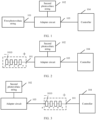
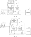
- the photovoltaic system includes an adapter circuit 103, a first photovoltaic string 101, a second photovoltaic string 102, and a controller 104.
- the first photovoltaic string 101 and the second photovoltaic string 102 are configured to provide electric energy for the controller 104.
- the adapter circuit 103 is configured to be connected to the first photovoltaic string 101 in series.
- the adapter circuit 103 is further configured to connect the second photovoltaic string 102 to the first photovoltaic string 101 in series when a voltage of the first photovoltaic string 101 is lower than a preset threshold.
- the controller 104 mentioned in this embodiment of this application may be an inverter, a combiner box, or another circuit, device, or the like having a direct current-alternating current conversion or string combination function.
- the description is applicable throughout the entire specification, and is not repeated below.
- the first photovoltaic string 101 includes one or more photovoltaic modules.
- the second photovoltaic string 102 includes one or more photovoltaic modules.
- the adapter circuit 103 includes a communications circuit.
- the communications circuit is configured to implement communication between the adapter circuit 103 and another circuit.
- the adapter circuit 103 receives a control instruction from the controller 104 by using the communications circuit.
- the control instruction is used to instruct the adapter circuit 103 to add the second string to the first string.
- the communications circuit may be a circuit based on a power line carrier (Power Line Carrier, PLC), RS485, wireless fidelity (Wireless-Fidelity, WI-FI), the zigbee protocol (zigbee), Lora, or an internet of things (Internet of things, IOT).
- PLC Power Line Carrier
- RS485 wireless fidelity
- WI-FI Wireless-Fidelity
- WI-FI wireless-Fidelity
- zigbee protocol zigbee
- Lora an internet of things (Internet of things, IOT).
- a working mode of an output end of the adapter circuit 103 includes a cut-in mode, a cut-out mode, a maximum power point tracking (Maximum Power Point Tracking, MPTT) mode, and a short-circuit mode.
- the cut-in mode means that when the voltage of the first string is lower than the preset threshold, the second string is connected to the first string.
- the cut-out mode means that when the voltage of the first string is relatively high, for example, the voltage of the first string exceeds the preset threshold, the adapter circuit 103 disconnects the first string from the controller 104.
- the MPTT mode means that the adapter circuit 103 can track a maximum power point and optimize output performance, to output maximum power.
- the short-circuit mode means that an output voltage of the adapter circuit 103 is 0.
- controller 104 may also work in an MPPT mode.
- the preset threshold includes a maximum allowable voltage of the photovoltaic system.
- the maximum allowable voltage is a lower voltage of a maximum input voltage of the controller 104 and a maximum output voltage of a photovoltaic string.
- the first threshold and the second threshold may be determined depending on a specific use scenario, and are not limited in this embodiment of this application.
- the voltage of the first photovoltaic string 101 may be detected by the adapter circuit 103, or may be detected by the controller 104.
- the adapter circuit 103 detects the voltage of the first photovoltaic string 101.
- the adapter circuit 103 detects the open-circuit voltage of the first photovoltaic string 101, and when the open-circuit voltage is less than or equal to the first threshold, the adapter circuit 103 connects the second photovoltaic string 102 to the first photovoltaic string 101 in series.
- the adapter circuit 103 detects the voltage to ground of the first photovoltaic string 101, and when detecting that the voltage to ground of the first photovoltaic string 101 is less than or equal to the second threshold, the adapter circuit 103 connects the second photovoltaic string 102 to the first photovoltaic string 101.
- the first photovoltaic string 101 and the adapter circuit 103 are connected in series in different manners.
- the voltage of the first photovoltaic string 101 is lower than the preset threshold means that the open-circuit voltage of the first photovoltaic string 101 is less than or equal to the first threshold.
- the adapter circuit 103 is connected to the first photovoltaic string 101 in series may be that an input end of the adapter circuit 103 is connected to an output end of the first photovoltaic string 101.
- the first photovoltaic string 101 includes four photovoltaic modules.
- That an input end of the adapter circuit 103 is connected to an output end of the first photovoltaic string 101 means that an output end, that is, an end e, of the entire first photovoltaic string 101 is connected to the input end of the adapter circuit 103.
- the output end of the adapter circuit 103 is connected to an input end of the controller 104.
- the output end of the adapter circuit 103 is connected to an input end, that is, an end a, of the entire first photovoltaic string 101.
- An output end of the first photovoltaic string 101 is connected to an input end of the controller 104.
- an input end of the adapter circuit 103 is connected to an output end of a front module of any two adjacent photovoltaic modules in the first photovoltaic string 101, and the output end of the adapter circuit 103 is connected to an input end of a rear module of the any two adjacent photovoltaic modules in the first photovoltaic string 101.
- the input end of the adapter circuit 103 is connected to an output end of a photovoltaic module 1012, and the output end of the adapter circuit 103 is connected to an input end of a photovoltaic module 1013.
- An output end of the photovoltaic module 1013 in the first photovoltaic string 101 is connected to an input end of the controller 104.
- the adapter circuit 103 may alternatively be connected between a photovoltaic module 1011 and the photovoltaic module 1012.
- a specific location of the adapter circuit 103 in the first photovoltaic string 101 is not limited in this embodiment of this application.
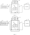
- that the adapter circuit 103 is connected to the first photovoltaic string 101 in series may be in a connection manner shown in FIG. 2 , which means that an input end of the adapter circuit 103 is connected to an output end of the entire first photovoltaic string 101; or may be in a connection manner shown in FIG. 3 , which means that the output end of the adapter circuit 103 is connected to an input end of the entire first photovoltaic string 101.
- a specific structure of the adapter circuit 103 may include the following two cases: Case 1: The adapter circuit 103 includes a control circuit 1031, a first switch K1, and a first element 1032.
- the photovoltaic system may have different specific structures.
- Three possible structures of the photovoltaic system provided in this embodiment of this application are as follows:
- a non-movable end of the first switch K1 is connected to the first end of the first element 1032 or an input end of the second photovoltaic string 102, a movable end of the first switch K1 is connected to the control circuit 1031, and the first switch K1 is configured to be opened or closed under control of the control circuit 1031, and connect the second photovoltaic string 102 to the first photovoltaic string 101 in a closed state. It should be noted that, when the controller 104 is not powered on, the first switch K1 is in an open-circuit state by default.
- an open-circuit state and an open state of a switch are a same concept.
- the description is applicable throughout the entire specification, and is not repeated below.
- the first switch K1 may be at least one of a mechanical switch, an electrical switch (for example, a switch of an electromagnetic relay type), and a power semiconductor (for example, an insulated gate bipolar transistor (IGBT, insulated gate bipolar transistor) switch).
- a mechanical switch for example, a switch of an electromagnetic relay type
- a power semiconductor for example, an insulated gate bipolar transistor (IGBT, insulated gate bipolar transistor) switch.
- IGBT insulated gate bipolar transistor
- An output end of the second photovoltaic string 102 is connected to the second end of the first element 1032.
- the control circuit 1031 is configured to: when the voltage of the first photovoltaic string 101 is lower than the preset threshold, control the first switch K1 to be closed.
- the first element 1032 is a transistor D1.
- the first element 1032 is the transistor D1
- a positive electrode of the transistor D1 is connected to the output end of the first photovoltaic string 101
- a negative electrode of the transistor D1 is connected to the input end of the controller 104.
- the transistor D1 When the controller 104 is not powered on, the transistor D1 is turned on to connect the first photovoltaic string 101 to the controller 104.
- the transistor D1 When the voltage of the first photovoltaic string 101 is lower than the preset threshold, the transistor D1 is cut off, to disable a path connection between the first photovoltaic string 101 and the controller 104.
- the transistor D1 When the voltage of the first photovoltaic string 101 exceeds the preset threshold or the controller 104 is not powered on, the transistor D1 is turned on. In this case, the path between the first photovoltaic string 101 and the controller 104 is formed.
- the first element 1032 may alternatively be a second switch K2.
- the first element 1032 is the second switch K2
- a non-movable end of the second switch K2 is connected to the output end of the first photovoltaic string 101 or the input end of the controller 104
- a movable end of the second switch K2 is connected to the control circuit 1031.
- the second switch K2 is configured to be closed by default when the controller 104 is not powered on, to form the path between the first photovoltaic string 101 and the controller 104.
- the second switch K2 is configured to separate the movable end from the input end of the controller 104 when the voltage of the first photovoltaic string 101 is lower than the preset threshold, for example, when the voltage of the first photovoltaic string 101 is relatively low, to disable the path between the first photovoltaic string 101 and the controller 104.
- the second switch K2 is further configured to separate the movable end from the input end of the controller 104 when the voltage of the first photovoltaic string 101 exceeds the preset threshold, to disable the path between the first photovoltaic string 101 and the controller 104, to avoid excessively high power input to the controller 104.
- the second switch K2 is configured to separate the movable end of the second switch K2 from the output end of the first photovoltaic string 101 when the voltage of the first photovoltaic string 101 is lower than the preset threshold, or the voltage of the first photovoltaic string 101 exceeds the preset threshold, to disable the path between the first photovoltaic string 101 and the controller 104.
- the second switch K2 may be at least one of a mechanical switch, an electrical switch (for example, a switch of an electromagnetic relay type), and a power semiconductor (for example, an insulated gate bipolar transistor (IGBT, insulated gate bipolar transistor) switch).
- a mechanical switch for example, a switch of an electromagnetic relay type
- a power semiconductor for example, an insulated gate bipolar transistor (IGBT, insulated gate bipolar transistor) switch.
- IGBT insulated gate bipolar transistor
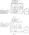
- FIG. 8 a structure of the photovoltaic system is as follows: A first end of the first element 1032 is connected to the first switch K1, and a second end of the first element 1032 is connected to the input end of the first photovoltaic string 101.
- the first element 1032 is configured to connect the first photovoltaic string 101 to the controller 104 when the controller 104 is not powered on, and further configured to disable a path between the first photovoltaic string 101 and the controller 104 when the voltage of the first photovoltaic string 101 is lower than the preset threshold or the voltage exceeds the preset threshold.
- a non-movable end of the first switch K1 is connected to the first end of the first element 1032 or the input end of the second photovoltaic string 102, a movable end of the first switch K1 is connected to the control circuit 1031, and the first switch K1 is configured to be opened or closed under control of the control circuit 1031, and connect the second photovoltaic string 102 to the first photovoltaic string 101 in a closed state.
- the controller 104 is not powered on, the first switch K1 is in an open state by default.
- An output end of the second photovoltaic string 102 is connected to the second end of the first element 1032.
- the control circuit 1031 is configured to: when the voltage of the first photovoltaic string 101 is lower than the preset threshold, control the first switch K1 to be closed.
- the output end of the first photovoltaic string 101 is connected to the controller 104.
- the transistor D1 when the first element 1032 is a transistor D1, a positive electrode of the transistor D1 is connected to the first switch K1, and a negative electrode of the transistor D1 is connected to the input end of the first photovoltaic string 101.
- the transistor D1 When the voltage of the first photovoltaic string 101 is lower than the preset threshold or the voltage exceeds the preset threshold, the transistor D1 is cut off, to disable a path connection between the first photovoltaic string 101 and the controller 104.
- the controller 104 When the controller 104 is not powered on, the transistor D1 is turned on. In this case, the path between the first photovoltaic string 101 and the controller 104 is formed.
- a non-movable end of the second switch K2 is connected to the first switch K1 or the input end of the first photovoltaic string 101, and a movable end of the second switch K2 is connected to the control circuit 1031.
- a specific structure of the photovoltaic system may be as follows: A first end of the first element 1032 is connected to the output end of the photovoltaic module 1012 in the first photovoltaic string 101, and a second end of the first element 1032 is connected to the input end of the photovoltaic module 1013 in the first photovoltaic string 101.
- the first element 1032 is configured to connect the first photovoltaic string 101 to the controller 104 when the controller 104 is not powered on, and further configured to disable a path between the first photovoltaic string 101 and the controller 104 when the voltage of the first photovoltaic string 101 is lower than the preset threshold, and to disable the path between the first photovoltaic string 101 and the controller 104 when the voltage of the first photovoltaic string 101 exceeds the preset threshold.
- a non-movable end of the first switch K1 is connected to the first end of the first element 1032 or an input end of the second photovoltaic string 102, a movable end of the first switch K1 is connected to the control circuit 1031, and the first switch K1 is configured to be opened or closed under control of the control circuit 1031, and connect the second photovoltaic string 102 to the first photovoltaic string 101 in a closed state.
- An output end of the second photovoltaic string 102 is connected to the second end of the first element 1032.
- the control circuit 1031 is configured to: when the voltage of the first photovoltaic string 101 is lower than the preset threshold, control the first switch K1 to be closed.
- the output end of the photovoltaic module 1013 at a tail end of the first photovoltaic string 101 is connected to the controller 104.
- the adapter circuit 103 is connected between the photovoltaic module 1012 and the photovoltaic module 1013 in the first photovoltaic string 101 in series is merely used as an example. In actual application, the adapter circuit 103 may be connected between any two adjacent photovoltaic modules in the first photovoltaic string 101 in series.
- the first element 1032 is a transistor D1
- a positive electrode of the transistor D1 is connected to the output end of the photovoltaic module 1012 in the first photovoltaic string 101
- a negative electrode of the transistor D1 is connected to the input end of the photovoltaic module 1013 in the first photovoltaic string 101.
- the transistor D1 is cut off, to disable a path connection between the first photovoltaic string 101 and the controller 104.
- the transistor D1 When the voltage of the first photovoltaic string 101 exceeds the preset threshold, the transistor D1 is cut off, to disable the path connection between the first photovoltaic string 101 and the controller 104. When the controller 104 is not powered on, the transistor D1 is turned on. In this case, the path between the first photovoltaic string 101 and the controller 104 is formed.
- a non-movable end of the second switch K2 is connected to the output end of the photovoltaic module 1012 in the first photovoltaic string 101 or the input end of the photovoltaic module 1013 in the first photovoltaic string 101, and a movable end of the second switch K2 is connected to the control circuit 1031.
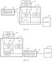
- the adapter circuit 103 includes a control circuit 1031, a converter circuit 1033, and a second element 1034.
- the photovoltaic system may also have different specific structures.
- Three possible structures of the photovoltaic system provided in this embodiment of this application are as follows:
- a first input end of the converter circuit 1033 is connected to an input end of the second photovoltaic string 102, a second input end of the converter circuit 1033 is connected to an output end of the second photovoltaic string 102, a first output end of the converter circuit 1033 is connected to the first end of the second element 1034, and a second output end of the converter circuit 1033 is connected to the second end of the second element 1034.
- the converter circuit 1033 is further connected to the control circuit 1031.
- the converter circuit 1033 is configured to connect the second photovoltaic string 102 to the first photovoltaic string 101 and output power to the controller 104 under control of the control circuit 1031. When the controller 104 is not powered on, an output voltage value between the first output end and the second output end of the converter circuit 1033 is 0 or a value less than a third threshold.
- the converter circuit 1033 may be a direct current-direct current (Direct Current-Direct Current, DC-DC) converter, or may be another circuit, device, or the like having a direct current-direct current conversion function.
- DC-DC direct current-direct current
- the converter circuit 1033 is a DC-DC converter.
- an input end of the DC-DC converter works in an MPTT mode. In this way, the DC-DC converter can track a maximum power point and optimize output performance, to output maximum power.
- an output end of the DC/DC converter works in a constant voltage mode or an adjustable mode.
- the constant voltage mode means that an output voltage of the DC-DC converter is a fixed value.
- inputting a voltage of a fixed value to the controller 104 having a constant voltage input requirement can optimize output performance of the controller 104.
- the adjustable mode means that an output voltage of the DC-DC converter is not a fixed value.
- a scanning speed in the MPTT mode of the DC-DC converter is different from a scanning speed of the controller 104, to reduce interference to power.
- Input power of the converter circuit 1033 is output power of the second photovoltaic string 102.
- the converter circuit 1033 converts, for example, steps up or down, the output power of the second photovoltaic string 102, to obtain output power between the first output end and the second output end of the converter circuit 1033.
- the converter circuit 1033 connects the second photovoltaic string 102 to the first photovoltaic string 101, which means that the first photovoltaic string 101 and the second photovoltaic string 102 jointly output power to the controller 104. This means that power that is output by the converter circuit 1033 to the controller 104, that is, input power of the controller 104, is greater than output power of the first photovoltaic string 101.
- the control circuit 1031 is configured to: when the voltage of the first photovoltaic string 101 is lower than the preset threshold, control output power of the converter circuit 1033.
- the control circuit 1031 is further configured to: when the controller 104 is not powered on, control the converter circuit 1033 to output a voltage 0 or output a voltage whose value is less than the third threshold.
- the second element 1034 is a transistor D1
- a positive electrode of the transistor D1 is connected to the output end of the first photovoltaic string 101
- a negative electrode of the transistor D1 is connected to the input end of the controller 104.
- the second element 1034 is a transistor D1
- a positive electrode of the transistor D1 is connected to the first output end of the converter circuit 1033
- a negative electrode of the transistor D1 is connected to the input end of the first photovoltaic string 101.
- a first end of the second element 1034 is connected to the output end of the photovoltaic module 1012 in the first photovoltaic string 101, and a second end of the second element 1034 is connected to the input end of the photovoltaic module 1013 in the first photovoltaic string 101.
- a positive electrode of the transistor D1 is connected to the output end of the photovoltaic module 1012 in the first photovoltaic string 101, and a negative electrode of the transistor D1 is connected to the input end of the photovoltaic module 1013 in the first photovoltaic string 101.
- a non-movable end of the second switch K2 is connected to the output end of the photovoltaic module 1012 in the first photovoltaic string 101 or the input end of the photovoltaic module 1013 in the first photovoltaic string 101, and a movable end of the second switch K2 is connected to the control circuit 1031.
- the photovoltaic system includes one adapter circuit and the adapter circuit controls connection of one string other than the first string is used as an example for description.
- the photovoltaic system may alternatively include two or more adapter circuits, and each adapter circuit may connect one or more photovoltaic strings to a current photovoltaic string in series.
- the adapter circuits may be connected in series or in parallel.
- Each adapter circuit may control one or more strings to be connected to a connected string in series, so that strings that are connected in series and that include more photovoltaic modules are connected to the photovoltaic system.
- FIG. 25 two adapter circuits are connected in series.
- FIG. 26 two adapter circuits are connected in parallel.
- an adapter circuit 1 and an adapter circuit 2 are connected in parallel, and the adapter circuit 1 and an adapter circuit 3 are connected in series.
- the photovoltaic system may further have the following structure:
- a switch (not shown in the figure) is disposed between the adapter circuit and the controller.
- the switch is configured to disable or enable a path between the adapter circuit and the controller.
- a switch may be disposed between the output end of the photovoltaic module 1013 and the controller.
- a switch is disposed between the second end of the diode and the input end of the photovoltaic module 1013.
- a switch is disposed between the output end of the first string and the positive electrode of the diode.
- a specific location of the switch may be flexibly determined depending on an application scenario. This is not limited herein.
- the photovoltaic system provided in this embodiment of this application includes the adapter circuit, the first photovoltaic string, the second photovoltaic string, and the controller.
- the first photovoltaic string and the second photovoltaic string are configured to provide electric energy for the controller.
- the adapter circuit is configured to be connected to the first photovoltaic string in series, and configured to connect the second photovoltaic string to the first photovoltaic string in series when the voltage of the first photovoltaic string is lower than the preset threshold.
- connecting the second photovoltaic string to the first photovoltaic string means that a quantity of photovoltaic strings that are connected to the photovoltaic system and that output power to the controller increases, so that a working voltage of an overall photovoltaic string can be increased, thereby increasing an electric energy yield.
- one adapter circuit may control the second photovoltaic string to be connected to the first photovoltaic string, which means that one adapter circuit may control a plurality of photovoltaic modules to be connected to the photovoltaic system in series. Therefore, there is no need to separately configure a connection control circuit for each photovoltaic module, thereby simplifying the structure of the photovoltaic system.
- a working process of the photovoltaic system includes the following steps.
- the first photovoltaic string is connected to the controller by using the first element in the adapter circuit.
- a string connected to the controller is the first photovoltaic string, and input power of the controller is equal to output power of the first photovoltaic string.
- the first photovoltaic string After the controller is powered on, the first photovoltaic string outputs power.
- the adapter circuit controls the first switch to be closed to connect the second string to the first string.
- a preset condition includes at least one of the following: The open-circuit voltage of the first photovoltaic string is less than or equal to the first threshold. The voltage to ground of the first photovoltaic string is less than or equal to the second threshold.
- the voltage of the first photovoltaic string may be detected by the controller, or a voltage detection procedure may be performed by the adapter circuit.
- the controller detects the open-circuit voltage or the voltage to ground of the first photovoltaic string, when detecting that the voltage to ground or the open-circuit voltage of the first photovoltaic string is lower than the preset threshold, the controller sends a control instruction to the adapter circuit, to notify the adapter circuit that the voltage of the first string is lower than the preset threshold.
- the adapter circuit controls a According to quantity of connected strings according to a voltage control policy determined by the adapter circuit.
- the adapter circuit determines, based on the voltage control policy of the adapter circuit, whether a voltage of all strings exceeds the preset threshold of the photovoltaic system after connection of another string. If the voltage of all the strings exceeds the preset threshold, the adapter circuit does not connect the another string to the first photovoltaic string. If the voltage of all the strings does not exceed the preset threshold after connection of the another string, the adapter circuit controls the another string to be connected to the first photovoltaic string.
- the voltage control policy may alternatively be determined by the controller and sent to the adapter circuit.
- the voltage control policy includes, but is not limited to, determining whether another string other than the first photovoltaic string needs to be connected to the photovoltaic system and a quantity of other strings that need to be connected to the photovoltaic system.
- the voltage of the first photovoltaic string may alternatively be detected by the adapter circuit.
- the photovoltaic string connected to the controller includes the first photovoltaic string and the second photovoltaic string.
- the input power of the controller is equal to a sum of output power of the first photovoltaic string and output power of the second photovoltaic string.
- the first element may be controlled by using the adapter circuit to disconnect the first string from the controller.
- another switch between the adapter circuit and the controller may be switched off to disconnect the first string from the controller.
- the first string may be connected to the controller by using the second element.
- a working process of the photovoltaic system may include the following steps.
- the voltage that is output by the adapter circuit has a relatively low value, a sum of the relatively low voltage value and the voltage of the first string does not exceed the preset threshold of the photovoltaic system.
- the adapter circuit After the controller is started, when the voltage of the first string is lower than the preset threshold, the adapter circuit outputs power, where a sum of the power and power of the first string is power that is input to the controller.
- the adapter circuit After the controller is started, when the voltage of the first string is greater than or equal to a fourth threshold, the adapter circuit output power, where the power is 0, or a value of the power is less than or equal to a fifth threshold.
- the adapter circuit limits output power of the adapter circuit to prevent the voltage of the string connected to the photovoltaic system from exceeding the preset threshold.
- the controller disconnects the first string from the controller.
- the first string may be connected to the controller by using the second element.
Landscapes
- Engineering & Computer Science (AREA)
- Power Engineering (AREA)
- Photovoltaic Devices (AREA)
- Control Of Electrical Variables (AREA)
Claims (3)
- Système photovoltaïque, comprenant un circuit d'adaptation (103), une première chaîne photovoltaïque (101), une deuxième chaîne photovoltaïque (102), et un contrôleur (104), le contrôleur (104) comportant un onduleur ou une boîte de combinaison ; etla première chaîne photovoltaïque (101) et la deuxième chaîne photovoltaïque (102) étant configurées de façon à fournir de l'énergie électrique pour le contrôleur (104) ; et le circuit d'adaptation (103) étant configuré de façon à être connecté en série à la première chaîne photovoltaïque (101) ;dans lequel, lorsqu'une tension de la première chaîne photovoltaïque (101) est plus basse qu'un seuil prédéterminé, le circuit d'adaptation (103) est configuré en outre de façon à : déterminer, en se basant sur une politique de contrôle de la tension du circuit d'adaptation (103), si une tension de la première chaîne photovoltaïque (101) et de la deuxième chaîne photovoltaïque (102) dépasse ou pas le seuil prédéterminé après la connexion de la deuxième chaîne photovoltaïque (102), la politique de contrôle de la tension comprenant la détermination si une autre chaîne autre que la première chaîne photovoltaïque (101) a besoin ou pas d'être connectée au système photovoltaïque et à une quantité d'autres chaînes qui ont besoin d'être connectées au système photovoltaïque ; et de façon à, en se basant sur la détermination que la tension de la première chaîne photovoltaïque (101) et de la deuxième chaîne photovoltaïque (102) ne dépasse pas le seuil prédéterminé, connecter en série la deuxième chaîne photovoltaïque (102) à la première chaîne photovoltaïque (101) ;le seuil prédéterminé comprenant une tension maximum admissible du système photovoltaïque, et la tension maximum admissible étant une tension plus basse parmi une tension d'entrée maximum du contrôleur (104) et une tension de sortie maximum de la première chaîne photovoltaïque (101),le circuit d'adaptation (103) comprenant :un circuit de commande (1031), un premier commutateur (K1) et un premier élément (1032),dans lequelune première extrémité du premier élément (1032) est connectée à une extrémité de sortie de la première chaîne photovoltaïque (101), une deuxième extrémité du premier élément (1032) est connectée à une extrémité d'entrée du contrôleur (104), et le premier élément (1032) est configuré de façon à connecter la première chaîne photovoltaïque (101) au contrôleur (104) lorsque le contrôleur (104) n'est pas sous tension, et est configuré en outre de façon à désactiver un chemin entre la première chaîne photovoltaïque (101) et le contrôleur (104) lorsque la tension de la première chaîne photovoltaïque (101) est plus basse que le seuil prédéterminé, et à désactiver le chemin entre la première chaîne photovoltaïque (101) et le contrôleur (104) lorsque la tension de la première chaîne photovoltaïque (101) dépasse le seuil prédéterminé ;une extrémité non mobile du premier commutateur (K1) est connectée à la première extrémité du premier élément (1032) ou à une extrémité d'entrée de la deuxième chaîne photovoltaïque (102), une extrémité mobile du premier commutateur (K1) est connectée au circuit de commande (1031), le premier commutateur (K1) est configuré de façon à être ouvert ou fermé sous la commande du circuit de commande (1031), et de façon à connecter en série la deuxième chaîne photovoltaïque (102) à la première chaîne photovoltaïque (101) dans un état fermé, et, lorsque le contrôleur (104) n'est pas sous tension, le premier commutateur (K1) est dans un état en circuit ouvert par défaut ;une extrémité de sortie de la deuxième chaîne photovoltaïque (102) est connectée à une extrémité de sortie du premier élément (1032) ; etle circuit de commande (1031) est configuré de façon à : lorsque la tension de la première chaîne photovoltaïque (101) est plus basse que le seuil prédéterminé, commander la fermeture du premier commutateur (K1).
- Système photovoltaïque selon la revendication 1, dans lequel le premier élément (1032) est un transistor (D1), une électrode positive du transistor (D1) est connectée à l'extrémité de sortie de la première chaîne photovoltaïque (101), et une électrode négative du transistor (D1) est connectée à l'extrémité d'entrée du contrôleur (104).
- Système photovoltaïque selon la revendication 1, dans lequel le premier élément (1032) est un deuxième commutateur (K2), une extrémité non mobile du deuxième commutateur (K2) est connectée à l'extrémité de sortie de la première chaîne photovoltaïque (101) ou à l'extrémité d'entrée du contrôleur (104), et une extrémité mobile du deuxième commutateur (K2) est connectée au circuit de commande (1031).
Applications Claiming Priority (2)
| Application Number | Priority Date | Filing Date | Title |
|---|---|---|---|
| CN201811641390.5A CN109638882B (zh) | 2018-12-29 | 2018-12-29 | 光伏系统 |
| PCT/CN2019/130037 WO2020135877A1 (fr) | 2018-12-29 | 2019-12-30 | Système photovoltaïque |
Publications (3)
| Publication Number | Publication Date |
|---|---|
| EP3855595A1 EP3855595A1 (fr) | 2021-07-28 |
| EP3855595A4 EP3855595A4 (fr) | 2021-10-27 |
| EP3855595B1 true EP3855595B1 (fr) | 2025-02-12 |
Family
ID=66054738
Family Applications (1)
| Application Number | Title | Priority Date | Filing Date |
|---|---|---|---|
| EP19906014.6A Active EP3855595B1 (fr) | 2018-12-29 | 2019-12-30 | Système photovoltaïque |
Country Status (4)
| Country | Link |
|---|---|
| US (1) | US11626738B2 (fr) |
| EP (1) | EP3855595B1 (fr) |
| CN (1) | CN109638882B (fr) |
| WO (1) | WO2020135877A1 (fr) |
Families Citing this family (4)
| Publication number | Priority date | Publication date | Assignee | Title |
|---|---|---|---|---|
| CN109638882B (zh) * | 2018-12-29 | 2022-08-09 | 华为数字技术(苏州)有限公司 | 光伏系统 |
| CN111565020A (zh) * | 2019-02-14 | 2020-08-21 | 阳光电源股份有限公司 | 一种组件限压方法及其应用装置和系统 |
| CN115552755A (zh) * | 2020-06-01 | 2022-12-30 | 华为数字能源技术有限公司 | 一种故障保护装置 |
| CN111695224B (zh) * | 2020-06-16 | 2023-09-05 | 浙江贝盛新能源开发有限公司 | 一种兆瓦级小型高效光伏电站设计方法及装置 |
Citations (2)
| Publication number | Priority date | Publication date | Assignee | Title |
|---|---|---|---|---|
| US20100288327A1 (en) * | 2009-05-13 | 2010-11-18 | National Semiconductor Corporation | System and method for over-Voltage protection of a photovoltaic string with distributed maximum power point tracking |
| US20110198935A1 (en) * | 2010-02-16 | 2011-08-18 | Greenvolts, Inc | Inverter for a three-phase ac photovoltaic system |
Family Cites Families (14)
| Publication number | Priority date | Publication date | Assignee | Title |
|---|---|---|---|---|
| US7602080B1 (en) * | 2008-11-26 | 2009-10-13 | Tigo Energy, Inc. | Systems and methods to balance solar panels in a multi-panel system |
| FR2923653B1 (fr) * | 2007-11-08 | 2009-11-27 | Harald Hauf | Procede de fonctionnement et dispositif de commande d'une installation energetique a modules photovoltaiques. |
| FR2946797B1 (fr) * | 2009-06-11 | 2012-03-23 | Photowatt Internat | Installation comprenant une pluralite de modules photovoltaique |
| US9287418B2 (en) * | 2012-06-29 | 2016-03-15 | Eaton Corporation | System and method for connection of photovoltaic arrays in series and parallel arrangements |
| US9356553B2 (en) * | 2013-03-15 | 2016-05-31 | Solantro Semiconductor Corp. | String continuity monitoring |
| CN203840274U (zh) * | 2013-12-18 | 2014-09-17 | 广西比迪光电科技工程有限责任公司 | 一种可变拓扑结构的太阳能光伏发电系统 |
| CN204031043U (zh) * | 2014-08-28 | 2014-12-17 | 常州天合光能有限公司 | 具有智能关断功能的光伏系统 |
| CN105811875A (zh) * | 2016-03-30 | 2016-07-27 | 西安理工大学 | 一种提升光伏发电系统发电量的光伏阵列变结构控制方法 |
| DE102016125219B4 (de) * | 2016-12-21 | 2019-01-17 | Sma Solar Technology Ag | Schaltung zur Spannungsbegrenzung in einem Photovoltaikfeld, Photovoltaikfeld und Verfahren zur Spannungsbegrenzung |
| CN106602504B (zh) * | 2017-02-28 | 2018-11-06 | 阳光电源股份有限公司 | 一种光伏快速关断装置及光伏系统 |
| US10931104B2 (en) * | 2017-05-30 | 2021-02-23 | Solaredge Technologies Ltd. | System and method for interconnected elements of a power system |
| CN107943194A (zh) * | 2017-10-25 | 2018-04-20 | 珠海格力电器股份有限公司 | 一种光伏组串及其串联控制方法、装置及光伏系统 |
| CN207543025U (zh) * | 2017-11-13 | 2018-06-26 | 丰郅(上海)新能源科技有限公司 | 可控制光伏组件被接入或旁路的串联式光伏发电系统 |
| CN109638882B (zh) * | 2018-12-29 | 2022-08-09 | 华为数字技术(苏州)有限公司 | 光伏系统 |
-
2018
- 2018-12-29 CN CN201811641390.5A patent/CN109638882B/zh active Active
-
2019
- 2019-12-30 WO PCT/CN2019/130037 patent/WO2020135877A1/fr not_active Ceased
- 2019-12-30 EP EP19906014.6A patent/EP3855595B1/fr active Active
-
2021
- 2021-06-22 US US17/353,925 patent/US11626738B2/en active Active
Patent Citations (2)
| Publication number | Priority date | Publication date | Assignee | Title |
|---|---|---|---|---|
| US20100288327A1 (en) * | 2009-05-13 | 2010-11-18 | National Semiconductor Corporation | System and method for over-Voltage protection of a photovoltaic string with distributed maximum power point tracking |
| US20110198935A1 (en) * | 2010-02-16 | 2011-08-18 | Greenvolts, Inc | Inverter for a three-phase ac photovoltaic system |
Also Published As
| Publication number | Publication date |
|---|---|
| CN109638882A (zh) | 2019-04-16 |
| WO2020135877A1 (fr) | 2020-07-02 |
| US11626738B2 (en) | 2023-04-11 |
| CN109638882B (zh) | 2022-08-09 |
| EP3855595A4 (fr) | 2021-10-27 |
| US20210313808A1 (en) | 2021-10-07 |
| EP3855595A1 (fr) | 2021-07-28 |
Similar Documents
| Publication | Publication Date | Title |
|---|---|---|
| US12255449B2 (en) | System and method for interconnected elements of a power system | |
| US11626738B2 (en) | Photovoltaic system | |
| EP3171478B1 (fr) | Onduleur photovoltaïque raccordé au réseau et son procédé de commande | |
| AU2020425507B2 (en) | Photovoltaic system | |
| JP6731607B2 (ja) | 電力変換システム | |
| US12107534B2 (en) | Photovoltaic system, inverter, and bus voltage control method for inverter | |
| US8809669B2 (en) | Photovoltaic arrays, in part having switches for short-circuiting of modules | |
| US10090701B2 (en) | Solar power generation system | |
| AU2013206703A1 (en) | Power converter module, photovoltaic system with power converter module, and method for operating a photovoltaic system | |
| US12074444B2 (en) | Power system | |
| WO2019213546A1 (fr) | Systèmes et procédés de conversion et de transmission de puissance en courant continu pour des champs solaires | |
| EP3485340A1 (fr) | Procédé de commande permettant d'améliorer le rendement de conversion d'un onduleur de mppt à canaux multiples | |
| EP3297117A1 (fr) | Système à puissance répartie, convertisseur cc-cc, et conditionneur d'énergie | |
| CN110429644B (zh) | 逆变装置及供电系统 | |
| EP4336697B1 (fr) | Système de production d'énergie photovoltaïque | |
| EP3944451A1 (fr) | Onduleur photovoltaïque, système photovoltaïque et procédé de commande de décharge | |
| KR20160129265A (ko) | 태양광 컨버터 및 에너지 저장 컨버터를 이용한 계통 연계형 통합 장치 | |
| US12051905B2 (en) | Power system | |
| KR20160129266A (ko) | 태양광 컨버터, 에너지 저장 컨버터 및 풍력 컨버터를 이용한 계통 연계형 통합 장치 | |
| CN112366751B (zh) | 一种不同特性组件混用的光伏系统 | |
| EP4311063A1 (fr) | Système d'alimentation électrique et procédé de commande de tension de sortie pour boîte de combinaison à courant continu | |
| EP3893374B1 (fr) | Systèmes de convertisseur de puissance avec stockage d'énergie intégré | |
| EP4181350B1 (fr) | Agencement de chargement de suiveur solaire |
Legal Events
| Date | Code | Title | Description |
|---|---|---|---|
| STAA | Information on the status of an ep patent application or granted ep patent |
Free format text: STATUS: THE INTERNATIONAL PUBLICATION HAS BEEN MADE |
|
| PUAI | Public reference made under article 153(3) epc to a published international application that has entered the european phase |
Free format text: ORIGINAL CODE: 0009012 |
|
| STAA | Information on the status of an ep patent application or granted ep patent |
Free format text: STATUS: REQUEST FOR EXAMINATION WAS MADE |
|
| 17P | Request for examination filed |
Effective date: 20210421 |
|
| AK | Designated contracting states |
Kind code of ref document: A1 Designated state(s): AL AT BE BG CH CY CZ DE DK EE ES FI FR GB GR HR HU IE IS IT LI LT LU LV MC MK MT NL NO PL PT RO RS SE SI SK SM TR |
|
| A4 | Supplementary search report drawn up and despatched |
Effective date: 20210924 |
|
| RIC1 | Information provided on ipc code assigned before grant |
Ipc: H02J 1/10 20060101ALI20210921BHEP Ipc: H02J 3/38 20060101AFI20210921BHEP |
|
| RAP1 | Party data changed (applicant data changed or rights of an application transferred) |
Owner name: HUAWEI DIGITAL POWER TECHNOLOGIES CO., LTD. |
|
| DAV | Request for validation of the european patent (deleted) | ||
| DAX | Request for extension of the european patent (deleted) | ||
| STAA | Information on the status of an ep patent application or granted ep patent |
Free format text: STATUS: EXAMINATION IS IN PROGRESS |
|
| 17Q | First examination report despatched |
Effective date: 20220908 |
|
| GRAP | Despatch of communication of intention to grant a patent |
Free format text: ORIGINAL CODE: EPIDOSNIGR1 |
|
| STAA | Information on the status of an ep patent application or granted ep patent |
Free format text: STATUS: GRANT OF PATENT IS INTENDED |
|
| INTG | Intention to grant announced |
Effective date: 20240801 |
|
| GRAS | Grant fee paid |
Free format text: ORIGINAL CODE: EPIDOSNIGR3 |
|
| GRAA | (expected) grant |
Free format text: ORIGINAL CODE: 0009210 |
|
| STAA | Information on the status of an ep patent application or granted ep patent |
Free format text: STATUS: THE PATENT HAS BEEN GRANTED |
|
| AK | Designated contracting states |
Kind code of ref document: B1 Designated state(s): AL AT BE BG CH CY CZ DE DK EE ES FI FR GB GR HR HU IE IS IT LI LT LU LV MC MK MT NL NO PL PT RO RS SE SI SK SM TR |
|
| REG | Reference to a national code |
Ref country code: GB Ref legal event code: FG4D |
|
| REG | Reference to a national code |
Ref country code: CH Ref legal event code: EP |
|
| REG | Reference to a national code |
Ref country code: DE Ref legal event code: R096 Ref document number: 602019065963 Country of ref document: DE |
|
| REG | Reference to a national code |
Ref country code: IE Ref legal event code: FG4D |
|
| REG | Reference to a national code |
Ref country code: NL Ref legal event code: MP Effective date: 20250212 |
|
| PG25 | Lapsed in a contracting state [announced via postgrant information from national office to epo] |
Ref country code: RS Free format text: LAPSE BECAUSE OF FAILURE TO SUBMIT A TRANSLATION OF THE DESCRIPTION OR TO PAY THE FEE WITHIN THE PRESCRIBED TIME-LIMIT Effective date: 20250512 |
|
| PG25 | Lapsed in a contracting state [announced via postgrant information from national office to epo] |
Ref country code: FI Free format text: LAPSE BECAUSE OF FAILURE TO SUBMIT A TRANSLATION OF THE DESCRIPTION OR TO PAY THE FEE WITHIN THE PRESCRIBED TIME-LIMIT Effective date: 20250212 |
|
| PG25 | Lapsed in a contracting state [announced via postgrant information from national office to epo] |
Ref country code: PL Free format text: LAPSE BECAUSE OF FAILURE TO SUBMIT A TRANSLATION OF THE DESCRIPTION OR TO PAY THE FEE WITHIN THE PRESCRIBED TIME-LIMIT Effective date: 20250212 |
|
| PG25 | Lapsed in a contracting state [announced via postgrant information from national office to epo] |
Ref country code: ES Free format text: LAPSE BECAUSE OF FAILURE TO SUBMIT A TRANSLATION OF THE DESCRIPTION OR TO PAY THE FEE WITHIN THE PRESCRIBED TIME-LIMIT Effective date: 20250212 |
|
| REG | Reference to a national code |
Ref country code: LT Ref legal event code: MG9D |
|
| PG25 | Lapsed in a contracting state [announced via postgrant information from national office to epo] |
Ref country code: IS Free format text: LAPSE BECAUSE OF FAILURE TO SUBMIT A TRANSLATION OF THE DESCRIPTION OR TO PAY THE FEE WITHIN THE PRESCRIBED TIME-LIMIT Effective date: 20250612 Ref country code: NO Free format text: LAPSE BECAUSE OF FAILURE TO SUBMIT A TRANSLATION OF THE DESCRIPTION OR TO PAY THE FEE WITHIN THE PRESCRIBED TIME-LIMIT Effective date: 20250512 |
|
| PG25 | Lapsed in a contracting state [announced via postgrant information from national office to epo] |
Ref country code: NL Free format text: LAPSE BECAUSE OF FAILURE TO SUBMIT A TRANSLATION OF THE DESCRIPTION OR TO PAY THE FEE WITHIN THE PRESCRIBED TIME-LIMIT Effective date: 20250212 |
|
| PG25 | Lapsed in a contracting state [announced via postgrant information from national office to epo] |
Ref country code: HR Free format text: LAPSE BECAUSE OF FAILURE TO SUBMIT A TRANSLATION OF THE DESCRIPTION OR TO PAY THE FEE WITHIN THE PRESCRIBED TIME-LIMIT Effective date: 20250212 |
|
| PG25 | Lapsed in a contracting state [announced via postgrant information from national office to epo] |
Ref country code: LV Free format text: LAPSE BECAUSE OF FAILURE TO SUBMIT A TRANSLATION OF THE DESCRIPTION OR TO PAY THE FEE WITHIN THE PRESCRIBED TIME-LIMIT Effective date: 20250212 Ref country code: PT Free format text: LAPSE BECAUSE OF FAILURE TO SUBMIT A TRANSLATION OF THE DESCRIPTION OR TO PAY THE FEE WITHIN THE PRESCRIBED TIME-LIMIT Effective date: 20250612 |
|
| PG25 | Lapsed in a contracting state [announced via postgrant information from national office to epo] |
Ref country code: BG Free format text: LAPSE BECAUSE OF FAILURE TO SUBMIT A TRANSLATION OF THE DESCRIPTION OR TO PAY THE FEE WITHIN THE PRESCRIBED TIME-LIMIT Effective date: 20250212 Ref country code: GR Free format text: LAPSE BECAUSE OF FAILURE TO SUBMIT A TRANSLATION OF THE DESCRIPTION OR TO PAY THE FEE WITHIN THE PRESCRIBED TIME-LIMIT Effective date: 20250513 |
|
| REG | Reference to a national code |
Ref country code: AT Ref legal event code: MK05 Ref document number: 1767041 Country of ref document: AT Kind code of ref document: T Effective date: 20250212 |
|
| PG25 | Lapsed in a contracting state [announced via postgrant information from national office to epo] |
Ref country code: SE Free format text: LAPSE BECAUSE OF FAILURE TO SUBMIT A TRANSLATION OF THE DESCRIPTION OR TO PAY THE FEE WITHIN THE PRESCRIBED TIME-LIMIT Effective date: 20250212 |
|
| PG25 | Lapsed in a contracting state [announced via postgrant information from national office to epo] |
Ref country code: SM Free format text: LAPSE BECAUSE OF FAILURE TO SUBMIT A TRANSLATION OF THE DESCRIPTION OR TO PAY THE FEE WITHIN THE PRESCRIBED TIME-LIMIT Effective date: 20250212 |
|
| PG25 | Lapsed in a contracting state [announced via postgrant information from national office to epo] |
Ref country code: DK Free format text: LAPSE BECAUSE OF FAILURE TO SUBMIT A TRANSLATION OF THE DESCRIPTION OR TO PAY THE FEE WITHIN THE PRESCRIBED TIME-LIMIT Effective date: 20250212 |
|
| PG25 | Lapsed in a contracting state [announced via postgrant information from national office to epo] |
Ref country code: IT Free format text: LAPSE BECAUSE OF FAILURE TO SUBMIT A TRANSLATION OF THE DESCRIPTION OR TO PAY THE FEE WITHIN THE PRESCRIBED TIME-LIMIT Effective date: 20250212 |
|
| PG25 | Lapsed in a contracting state [announced via postgrant information from national office to epo] |
Ref country code: AT Free format text: LAPSE BECAUSE OF FAILURE TO SUBMIT A TRANSLATION OF THE DESCRIPTION OR TO PAY THE FEE WITHIN THE PRESCRIBED TIME-LIMIT Effective date: 20250212 |
|
| PG25 | Lapsed in a contracting state [announced via postgrant information from national office to epo] |
Ref country code: EE Free format text: LAPSE BECAUSE OF FAILURE TO SUBMIT A TRANSLATION OF THE DESCRIPTION OR TO PAY THE FEE WITHIN THE PRESCRIBED TIME-LIMIT Effective date: 20250212 Ref country code: CZ Free format text: LAPSE BECAUSE OF FAILURE TO SUBMIT A TRANSLATION OF THE DESCRIPTION OR TO PAY THE FEE WITHIN THE PRESCRIBED TIME-LIMIT Effective date: 20250212 |
|
| PG25 | Lapsed in a contracting state [announced via postgrant information from national office to epo] |
Ref country code: RO Free format text: LAPSE BECAUSE OF FAILURE TO SUBMIT A TRANSLATION OF THE DESCRIPTION OR TO PAY THE FEE WITHIN THE PRESCRIBED TIME-LIMIT Effective date: 20250212 |
|
| PG25 | Lapsed in a contracting state [announced via postgrant information from national office to epo] |
Ref country code: SK Free format text: LAPSE BECAUSE OF FAILURE TO SUBMIT A TRANSLATION OF THE DESCRIPTION OR TO PAY THE FEE WITHIN THE PRESCRIBED TIME-LIMIT Effective date: 20250212 |
|
| REG | Reference to a national code |
Ref country code: DE Ref legal event code: R097 Ref document number: 602019065963 Country of ref document: DE |
|
| PLBE | No opposition filed within time limit |
Free format text: ORIGINAL CODE: 0009261 |
|
| STAA | Information on the status of an ep patent application or granted ep patent |
Free format text: STATUS: NO OPPOSITION FILED WITHIN TIME LIMIT |
|
| PGFP | Annual fee paid to national office [announced via postgrant information from national office to epo] |
Ref country code: DE Payment date: 20251104 Year of fee payment: 7 |
|
| 26N | No opposition filed |
Effective date: 20251113 |