EP3855642A1 - Diversité des fréquences temporelles hf ad hoc - Google Patents
Diversité des fréquences temporelles hf ad hoc Download PDFInfo
- Publication number
- EP3855642A1 EP3855642A1 EP21152588.6A EP21152588A EP3855642A1 EP 3855642 A1 EP3855642 A1 EP 3855642A1 EP 21152588 A EP21152588 A EP 21152588A EP 3855642 A1 EP3855642 A1 EP 3855642A1
- Authority
- EP
- European Patent Office
- Prior art keywords
- node
- transmission
- relay
- further configured
- originating
- Prior art date
- Legal status (The legal status is an assumption and is not a legal conclusion. Google has not performed a legal analysis and makes no representation as to the accuracy of the status listed.)
- Granted
Links
Images




Classifications
-
- H—ELECTRICITY
- H04—ELECTRIC COMMUNICATION TECHNIQUE
- H04W—WIRELESS COMMUNICATION NETWORKS
- H04W84/00—Network topologies
- H04W84/18—Self-organising networks, e.g. ad-hoc networks or sensor networks
-
- H—ELECTRICITY
- H04—ELECTRIC COMMUNICATION TECHNIQUE
- H04B—TRANSMISSION
- H04B7/00—Radio transmission systems, i.e. using radiation field
- H04B7/02—Diversity systems; Multi-antenna system, i.e. transmission or reception using multiple antennas
- H04B7/04—Diversity systems; Multi-antenna system, i.e. transmission or reception using multiple antennas using two or more spaced independent antennas
- H04B7/06—Diversity systems; Multi-antenna system, i.e. transmission or reception using multiple antennas using two or more spaced independent antennas at the transmitting station
-
- H—ELECTRICITY
- H04—ELECTRIC COMMUNICATION TECHNIQUE
- H04B—TRANSMISSION
- H04B7/00—Radio transmission systems, i.e. using radiation field
- H04B7/14—Relay systems
- H04B7/15—Active relay systems
- H04B7/155—Ground-based stations
- H04B7/15564—Relay station antennae loop interference reduction
- H04B7/15585—Relay station antennae loop interference reduction by interference cancellation
-
- H—ELECTRICITY
- H04—ELECTRIC COMMUNICATION TECHNIQUE
- H04B—TRANSMISSION
- H04B7/00—Radio transmission systems, i.e. using radiation field
- H04B7/14—Relay systems
- H04B7/15—Active relay systems
- H04B7/155—Ground-based stations
- H04B7/15592—Adapting at the relay station communication parameters for supporting cooperative relaying, i.e. transmission of the same data via direct - and relayed path
-
- H—ELECTRICITY
- H04—ELECTRIC COMMUNICATION TECHNIQUE
- H04B—TRANSMISSION
- H04B7/00—Radio transmission systems, i.e. using radiation field
- H04B7/22—Scatter propagation systems, e.g. ionospheric, tropospheric or meteor scatter
-
- H—ELECTRICITY
- H04—ELECTRIC COMMUNICATION TECHNIQUE
- H04W—WIRELESS COMMUNICATION NETWORKS
- H04W72/00—Local resource management
- H04W72/04—Wireless resource allocation
- H04W72/044—Wireless resource allocation based on the type of the allocated resource
- H04W72/0446—Resources in time domain, e.g. slots or frames
-
- H—ELECTRICITY
- H04—ELECTRIC COMMUNICATION TECHNIQUE
- H04W—WIRELESS COMMUNICATION NETWORKS
- H04W72/00—Local resource management
- H04W72/50—Allocation or scheduling criteria for wireless resources
- H04W72/54—Allocation or scheduling criteria for wireless resources based on quality criteria
- H04W72/541—Allocation or scheduling criteria for wireless resources based on quality criteria using the level of interference
-
- H—ELECTRICITY
- H04—ELECTRIC COMMUNICATION TECHNIQUE
- H04W—WIRELESS COMMUNICATION NETWORKS
- H04W74/00—Wireless channel access
- H04W74/08—Non-scheduled access, e.g. ALOHA
- H04W74/0808—Non-scheduled access, e.g. ALOHA using carrier sensing, e.g. carrier sense multiple access [CSMA]
Definitions
- Ad hoc high frequency communication systems may be utilized to provide beyond line of sight high frequency (HF) radio frequency communications in various types of operating conditions.
- HF communication systems are typically configured to handle two nodes in communication using traditional HF contention-based waveforms.
- These nodes are typically configured to keep track of other potential nodes during idle periods and use the potential nodes if the current communication link breaks. It is noted that if other nodes are used, those nodes will typically retransmit the transmission with the same control parameters as the originating node. It is also noted that there are performance issues associated with existing ad hoc HF communication systems.
- a high-frequency beyond line of sight ad-hoc communication system includes an originating node.
- the originating node is configured to transmit a transmission.
- the system includes a destination node.
- the destination node is configured to receive the transmission using one or more antennas.
- the system includes one or more relay nodes.
- the one or more relay nodes are configured to relay the transmission from the operating mode to the destination mode in a time diverse manner.
- the one or more relay nodes further comprise a controller.
- the controller is configured to facilitate high-frequency beyond line of sight communication between the originating node and the destination node, wherein the transmission is carried in accordance with a time division multiple access (TDMA) based waveform that supports frames and time slots.
- TDMA time division multiple access
- the one or more relay nodes are further configured to relay the transmission from the originating mode to the destination mode in a frequency diverse and/or a spatially diverse manner.
- the system includes an originating node.
- the originating node is configured to transmit a transmission.
- the system includes a destination node.
- the destination node is configured to receive the transmission using one or more antennas.
- the system includes one or more relay nodes.
- the one or more relay nodes are configured to relay the transmission from the operating mode to the destination mode in a frequency diverse manner.
- the one or more relay nodes further comprise a controller.
- the controller is configured to facilitate high-frequency beyond line of sight communication between the originating node and the destination node, wherein the transmission is carried in accordance with a time division multiple access (TDMA) based waveform that supports frames and time slots.
- TDMA time division multiple access
- the one or more relay nodes are further configured to relay the transmission from the originating mode to the destination mode in a time diverse and/or a spatially diverse manner.
- a letter following a reference numeral is intended to reference an embodiment of the feature or element that may be similar, but not necessarily identical, to a previously described element or feature bearing the same reference numeral (e.g., 1, 1a, 1b).
- reference numeral e.g. 1, 1a, 1b
- Such shorthand notations are used for purposes of convenience only and should not be construed to limit the disclosure in any way unless expressly stated to the contrary.
- any reference to “one embodiment” or “some embodiments” means that a particular element, feature, structure, or characteristic described in connection with the embodiment is included in at least one embodiment disclosed herein.
- the appearances of the phrase “in some embodiments” in various places in the specification are not necessarily all referring to the same embodiment, and embodiments may include one or more of the features expressly described or inherently present herein, or any combination of sub-combination of two or more such features, along with any other features which may not necessarily be expressly described or inherently present in the instant disclosure.
- Embodiments of the inventive concepts here are directed to high frequency (HF) communication systems capable of supporting HF tactical communications using relay nodes utilizing a single transmitter, and destination nodes capable of diversity reception while using a single antenna, the relay nodes cooperatively simulating a multiple input single output (MISO) or multiple input multiple output (MIMO) communication system.
- HF high frequency
- HF communications used in low-angle skywave systems were organized as point-to-point systems (e.g., no relays), while HF communications using near vertical incidence skywave (NVIS), ground wave or sea wave signals could be networked using a single frequency.
- NVIS near vertical incidence skywave
- BLOS low-angle beyond-line-of-sight
- the waveform may be a time division multiple access (TDMA) based waveform that supports time slots.
- the time slots can be allocated to users statically and/or dynamically for different purposes, including transmissions of data, voice, situational awareness, network management, as well as other overhead information.
- TDMA time division multiple access
- a TDMA based waveform e.g., which has the concept of time slots, groups of slots referred to as frames, and groups of frames referred to as epochs
- a conventional point to point contention-based waveform e.g., which does not depend on the knowledge of time).
- a TDMA based waveform may be better suited to support a large number of nodes, and that many of these nodes may be used to receive and retransmit data as a relay node, provide improved efficiency, efficacy, and resource allocation compared to a conventional contention-based waveform.
- FIG. 1A is a diagram depicting a communication system 100 in accordance with the inventive concepts disclosed herein.
- the communication system 100 includes an originating node 104.
- the originating node initially codes and transmits a transmission 108 in the communication system 100.
- the originating node 104 transmits from high-gain antennas with powerful amplifiers (e.g., from fixed-site nodes or maritime nodes with 1kW to 10kW capabilities).
- power constrained systems may be used as the originating node (e.g., vehicular, airborne or other mobile platforms).
- the communication system 100 further includes a destination node 112.
- the destination node 112 is the intended receiver of the transmission 108, where it both receives and decodes the transmission 108.
- the destination node 112 is a single antenna capable of receiving multiple channels simultaneously.
- the destination node 112 may be a single antenna receiver capable of receiving multiple transmissions that have been transmitted using different power levels (e.g., through successive interference cancellation as described herein).
- the destination node 112 may be a single antenna receiver capable of receiving up to six channels simultaneously (e.g., up to six different frequencies within the maximum and least usable frequency (MUF/LUF)).
- MUF/LUF maximum and least usable frequency
- receivers utilize one or more processors (e.g., FPGA, SoC, or IC) to process (e.g., digitize) incoming signals.
- processors e.g., FPGA, SoC, or IC
- the multi-frequency receivers are also capable of decoding several slot bursts per frame.
- the destination node 112 is a wideband HF receiver. In some embodiments, the destination node 112 is a wide band HF receiver along with a traditional HF receiver. For example, the wideband HF receiver may receive and digitize the entire spectrum, allowing reception of a single frequency or multiple frequency by the traditional HF receiver.
- the communication system 100 includes one or more relay nodes 116a-c.
- the relay nodes 116a-c are configured to opportunistically receive a transmission from the originating node 104 and retransmit the transmission 108 to the destination node 112.
- the relay nodes 116a-c include a controller 120.
- FIG. 1B is a block diagram illustrating a controller 120 for a relay node 116a-c, in accordance with one or more embodiments of this disclosure.
- the controller 120 provides processing functionality for the relay node and can include any number of processors 124.
- the one or more processors 124 may include any processors 124 used in the art including, but not limited to, field programmable gate arrays (FPGA), and application-specific integrated circuits (ASIC).
- the controller may utilize the one or more processors 124 to receive and decode incoming transmissions and recode and retransmit the relayed transmissions.
- the controller may also include resident or external memory 128 for storing data, executable code, and other information accessed or generated by the relay node 116.
- the controller 120 can execute one or more software programs embodied in a non-transitory computer readable medium (e.g., a memory 128) that implements techniques described herein.
- the controller 120 is not limited by the materials from which it is formed or the processing mechanisms employed therein.
- the memory 128 can be an example of a tangible, computer-readable storage medium that provides storage functionality to store various data and/or program code associated with operation of the relay node 116 and or controller 120, such as software programs and/or code segments, or other data to instruct the controller 120, and possibly other components of the relay node 116.
- the memory 128 can store data, such as a program of instructions for operating the relay node 116 and/or incoming data from the transmission 108. It should be noted that while a single memory 106 is described, a wide variety of types and combinations of memory 128 (e.g., tangible, non-transitory memory) can be employed.
- the memory 128 can be integral with the controller 104, can comprise stand-alone memory, or can be a combination of both.
- the memory 128 can include removable and non-removable memory components, such as random-access memory (RAM), read-only memory (ROM), flash memory (e.g., a secure digital (SD) memory card, a mini-SD memory card, and/or a micro-SD memory card), solid-state drive (SSD) memory, magnetic memory, optical memory, universal serial bus (USB) memory devices, hard disk memory, external memory, and so forth.
- RAM random-access memory
- ROM read-only memory
- flash memory e.g., a secure digital (SD) memory card, a mini-SD memory card, and/or a micro-SD memory card
- SSD solid-state drive
- magnetic memory magnetic memory
- optical memory optical memory
- USB universal serial bus
- the relay node includes a communication interface 132.
- the communication interface man be operatively configured to communicate with the components of the relay node 116 and the controller 120.
- the communication interface 132 can be configured to retrieve data from the controller 120 or other devices, transmit data for storage in memory 128, retrieve data from storage in memory, 128 and so forth.
- the communication interface 108 can also be communicatively coupled with the controller 120 to facilitate data transfer between components of the relay node 116 and the controller 120.
- the communication interface 132 is described as a component of the relay node 128, one or more components of the communication interface 132 can be implemented as external components communicatively coupled to the relay node 116 via a wire and/or wireless connection.
- the relay node 116 may also include and/or connect to one or more input/output (I/O) devices.
- the communication interface 132 includes or is coupled to a transmitter, receiver, transceiver, physical connection interface, or any combination thereof.
- the relay nodes 116a-c are selected to reduce the time of transmission and/or increase the data rate of a transmission of a signal that would have originally been transmitted without a relay. In some embodiments, the relay nodes 116a-c are selected to increase the robustness of a signal that would have originally been transmitted without a relay (e.g., through a multipath strategy).
- the relay node 116 may be or have been performing as a node in a separate communication system (e.g., acting as an originating, destination or relay node). In this situation, the originating node 104 contacts the relay node 116 to determine if the relay node 116 can assist in relaying a transmission 108 to the destination node 112.
- the ability of the opportunistic relay node 116 to assist the originating node 104 in relaying the transmission 108 may depend on several parameters including, but not limited to, the authority level of the originating node 104, the importance of the transmission 108, the transmission schedule of the relay node 116, and the probability of successfully retransmitting the transmission 108 to the destination node 112 than the originating node.
- the relay node 116 Once the relay node 116 has acknowledged the ability to retransmit a transmission 108 to the destination node 112, the originating node 104 will begin transmitting the transmission 108 to the relay node 116.
- FIG. 1 presents three relay nodes 116a-c in the communication system 100.
- the number of relay nodes 116a-c may vary between different communication systems 100.
- a communication system 100 may contain one relay node 116a.
- a communication system may contain 10 relay nodes 116a-c.
- a communication system may contain 264 relay nodes.
- relay nodes may consist of power constrained airborne, vehicular, or other mobile units (e.g., less than 1 kW).
- larger fixed site nodes or maritime nodes may also be used as a relay node, therefore the above description should not be interpreted as a limitation of the present disclosure, but merely an illustration.
- the communication system 100 takes advantage of spatial diversity to ensure that the transmission 108 reaches the destination node 112.
- Spatial diversity is a cooperative communication method where relays located at varied geographical points are used to relay the same transmission 108 from the originating node 104 to the destination node 112.
- relay node 116a geographically located a distance from both the originating node 104 and destination node 112 is able to receive the transmission 108 from the originating node and retransmit the transmission to the destination node.
- geographically separated relay nodes 116b and 116c are also able to receive the transmission 108 from the originating node 104 and retransmit the transmission to the destination node. Having multiple relay nodes 116a-c receiving and retransmitting the same transmission 108 increases the probability that the entirety of the transmission will successfully reach the destination node 112.
- FIGS. 2A-2D An example embodiment of cooperative communication through spatial diversity using relay nodes 116a-c are shown in FIGS. 2A-2D .
- a transmission is planned to be sent from an originating node 112 in Node A to the destination node 116 at Node B.
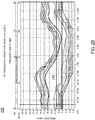
- FIG. 2A is a graph 200 showing the prediction of propagation of HF signals from Node A to Node B, in accordance with one or more embodiments of this disclosure.
- Competent propagation of a HF signal requires high signal-to-noise (SNR) ranges that vary with time. Operators use automatic link establishment (ALE) protocols to determine the highest data rate that can be supported by current SNR conditions, as SNR can vary drastically depending on the time of day.
- SNR signal-to-noise
- ALE automatic link establishment
- the SNR from node A to node B would range from a paltry 1 dB to 10 dB. Under these conditions (e.g., 10dB SNR), a 3 kHz bandwidth can deliver 2400 bps. However, the SNR improves later in the day.
- the maximum SNR 210 is predicted to be between 19 dB and 29 dB in a 3 kHz bandwidth, which can support data transmission at 16000 bps. It is noted that in order to transmit under maximal SNR 210, the frequencies used in the transmission will need to vary, requiring the originating node to vary the frequency at the appropriate time. Overall, the window of the maximal SNR 210 is rather narrow for a transmission to be sent from Node A to Node B with a high bit rate (e.g., over 20000 bps).
- FIG. 2B is a graph showing the prediction of the propagation of HF signals from Node A to Node C, in accordance with one or more embodiments of this disclosure.
- the predicted SNR for Node A to Node C propagation is generally higher than in the Node A to Node B prediction, with the maximal SNR 210 ranging from 25 dB to 37 dB, versus 19 dB to 29 predicted SNR for Node A to Node B.
- the window of the maximal SNR 210 is also considerably broader. At points where the SNR is approximately 37 dB, a wider channel of 9 kHz can be used, allowing data throughputs of 48000 bps.
- FIG. 2C is a graph showing the prediction of the propagation of HF signals from Node B to Node C, in accordance with one or more embodiments of this disclosure. Similar to the predicted propagation for Node A to Node C in FIG. 2B , the SNR has a high quartile of predicted SNR ranges (e.g., 28 dB to 40 dB) and a broad window of maximal SNR 210 that runs continuously through the day, allowing data throughputs of 48000 bps.
- the high SNR values shown in FIGS. 2B and 2C suggest that Node C could act as a relay node for a transmission from Node A to Node B with an overall greater bit rate than what would be possible for a direct communication between Node A and Node B.
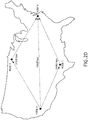
- FIG. 2D is a map of the contiguous United States showing possible routes of a HF transmission from Node A to Node B, in accordance with one or more embodiments of this disclosure.
- One of the possible routes for transmission is a direct hop from Node A to Node B, as referred to in FIG 2A .
- the low predicted SNR for this route also predicts a low average bit rate of 10600 bps.
- Node C as a relay, which has a higher predicted SNR for both Node A to Node C transmissions and Node B to Node C transmissions, a greater average predicted bit rate of 24000 bps is calculated.
- a similar increase in average predicted bit rate is seen when considering a second relay node 116 at Node D.
- an overall bit rate bit rate of 31500 bps was predicted for a transmission from Node A to Node B using Node D as a relay node. Therefore, the use of either Node C or Node D as a relay node is predicted to more than double the bit rate of a direct transmission between Node A and Node B.
- Spatial diversity allows an operator to choose a path around atmospheric disturbances, jamming devices, and other interfering phenomena.
- By taking advantage of available spatially diverse relay nodes further increases in transmission efficiency can be seen by sending the same transmission through multiple paths (e.g., each using one or more relay nodes) in a cooperative communication scheme.
- Selecting multiple relays to transmit simultaneously on the same frequency transforms the relay channel into a Multiple Input Single Output (MISO) like channel, which has the benefit of reducing the required SNR by a factor proportional to 1/SNR L , where L is the number of relays.
- MISO Multiple Input Single Output
- sending the same transmission through Node A and Node B decreases the outage probability for the transmission than if only one path were used.
- up to six relay nodes 116 may opportunistically receive a transmission 108 and retransmit the transmission 108 towards the destination node 112. In this instance, using six relay nodes 116 reduces the outage probability below 0.5%.
- the utilization of three relays reduces the average required SNR by approximately 10 dB. This 10dB reduction can substantially increase bit rates in a transmission.
- the transmission 108 is transmitted at a higher throughput (e.g., with greater capacity) than can be sustained individually for a given available SNR.
- Increased throughput of spatial diversity transmissions may be achieved by partitioning the transmission between two or more nodes 116.
- nodes 116a and 116b may transmit the even packets of a transmission
- node 116c e.g., and possibly another node 116
- the advantages of signal diversity are seen (e.g., increased probability of reception) along with a reduction of overall transmission time.
- the relay nodes 116 in the communication system 100 need only one antenna to receive and retransmit a transmission.
- the destination node 112 may also necessitate only one antenna if the signals from more than one relay nodes arrive instantaneously.
- legacy HF and WBHF receivers are not capable of diversity reception.
- non-instantaneous transmission e.g., through latency of the relay protocol or spatial delays
- require diversity reception capability e.g., HFGCS receivers, triple diversity receivers, and other multichannel receivers.
- control information sent from the originating node 104 may be exchanged between multiple relay nodes 116 that permit periodical time alignment of the relay node transmissions, permitting the transmissions 108 that are sent from the relay nodes 116 to arrive at the destination node 112 simultaneously, allowing reception by legacy HF and WBHF receivers.
- the relay nodes 116 of the communication system 100 are configured to use collaborative signal processing (CSP).
- CSP collaborative signal processing
- SIC successive interference modulation
- CSP collaborative signal processing
- SIC successive interference modulation
- SIC is used to isolate and decode simultaneously arriving packets by demodulating the strongest source based on a preamble detection metric, then canceling it out and iteratively decoding the next strongest signal.
- SIC is used to decode more than two simultaneous packets.
- the advantage of using of diversity-capable receivers with non-instantaneous transmissions sent from relay nodes 116 over instantaneous transmission is substantial. For example, a lightning strike in the vicinity of the destination node lasting 30 milliseconds (ms) may interfere with 30 ms of transmission, preventing the entire transmission from being received and decoded. Having a diversity of transmission spread over time allows multiple copies of the transmission to be received by the receiver. Sections of one transmission lost to the lightning strike may be regained by comparing the transmission 108 to another transmission 108 with a different time characteristic. By comparing multiple transmissions 108, a complete transmission 108 may be received and decoded.
- FIG. 3 is a diagram depicting a communication system 100 configured for single frequency transmit diversity relaying, in accordance with one or more embodiments of this disclosure.
- the originating node 104 transmits a transmission 108 to one or more relay nodes 316a-c.
- Each relay node 316a-c may incorporate one or more unique time delays (e.g., T 1 , T 2 , and T 3 ) that alters the time that the retransmission will reach the destination node 112.
- the time delay may be the result of multiple factors, including but not limited to, time delays purposefully set through instruction control data, spatial distances between nodes, and the latency of the relay node to receive and retransmit transmission. These time delays are coordinated so that the multiple relayed transmissions do not interfere with each other.
- the destination node 112 may then receive and decode retransmissions from one or more of the relay nodes 316a-c.
- Relay nodes 116 are also capable of receiving transmissions with one frequency, then retransmitting the message with a different frequency.
- a relay node 116 may change the frequency of the transmission to one that is suboptimal for interference by jamming devices that may be used between the relay node 116 and the destination node 112. Using multiple frequencies may also overwhelm a jammer's capabilities. For instance, six relays retransmitting the same transmission on six different frequencies would require the jammer to either dedicate 1/6 of power resources to jam each frequency, or divide power resources unequally, reducing interference in some channels.
- a relay node 116 may change the frequency of a transmission to one that is less affected by adverse SNR levels. For instance, in the graphs shown in FIGS.
- an 11 MHz transmission send from Node A at 0600 UTC to Node C would have an advantageous SNR range and capabilities to transmit at a high bit rate.
- retransmitting the transmission to Node B at the same frequency with the same high bit rate is not possible due to the lower SNR range at that time.
- a different frequency e.g., 6 to 8 kHz
- the transmission may be retransmitted at the same bit rate.
- having both Node C and Node D act as frequency optimizing relay nodes would further optimize the probability and efficiency of transmission reception.
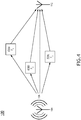
- FIG. 4 is a diagram depicting a communication system 100 configured for multiple frequency transmit diversity relaying, in accordance with one or more embodiments of the disclosure.
- the originating node 104 transmits a transmission 108 to one or more relay nodes 416a-c.
- Each relay node 416a-c may alter the frequency upon retransmission (e.g., to frequencies F 1 , F 2 , and/or F 3 ), where the retransmission may be received and decoded by a destination node capable of frequency diversity reception.
- a communication system 100 may incorporate polarization diversity.
- one or more relay nodes 116 may relay (e.g., retransmit) a transmission 108 to the destination node 112 that has different polarization characteristics than the transmission 108 that was sent from the originating node 104 to the relay node 116.
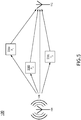
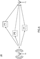
- FIG. 5 is a diagram depicting the communication system 100 configured for polarization diversity, in accordance with one or more embodiments of the disclosure. In this communication system 100, the originating node 104 transmits a transmission 108 to three relay nodes 516a-c.
- Each relay node 516a-c may alter the polarization (e.g., polarizations P 1 , P 2 and/or P 3 ) of the transmission 108 upon retransmission.
- the polarizations of signals sent from two relays nodes 516a-b may be orthogonal to each other.
- a third relay node 516c may retransmit the transmission 108 with a polarization (e.g., P 3 ) similar to P 1 or P 2 , or may utilize a separate polarization scheme.
- the retransmission may be received and decoded by a destination node 112 capable of polarization diversity reception. It is noted that polarization diversity may be better suited for LOS transmissions than BLOS transmissions, as ionospheric reflection of BLOS signals can cause fluctuations in polarization.
- a communication system 100 may incorporate time delay diversity with multi-frequency diversity.
- FIG. 6 is a diagram depicting a communication system 100 configured for time delay diversity and multiple frequency transmit diversity relaying, in accordance with one or more embodiments of this disclosure.
- the transmission 108 may also be opportunistically received and retransmitted by one or more relay nodes 616a-c in a time and frequency diverse manner.
- Each relay node 616a-c may alter the frequency upon retransmission (e.g., to frequencies F 1 , or F 2 ) as well as incorporating a time delay (e.g., T 1 , or T 2 ).
- the multi-channel receivers exist that receive up to six channels, simultaneously.
- the receiver may receive a single transmission from six relay nodes 116, each at a different frequency.
- the receiver may receive transmissions synchronized to two time points, with each time point transmitting in three different frequencies.
- the receiver may receive transmissions from synchronized to three time points, with each time point transmitting in two different frequencies.
- spatial diversity may be incorporated into time-diverse communications, frequency-diverse communications, or time- and frequency-diverse communications. Therefore, the above description should not be interpreted as a limitation of the present disclosure, but merely as an illustration.
- all nodes described within embodiments of the communication system 100 may possesses at least one of a controller 120, a memory 128, a processor 124 or a communication interface 132. Therefore, the above description should not be interpreted as a limitation, but merely as an illustration.
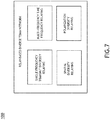
- FIG. 7 is a block diagram of a communication system 100 with multiple diversity components, in accordance with one or more embodiments of this disclosure.
- more than one diversity scheme can be implemented at one time, as time-diverse and a frequency-diverse signals were retransmitted from relay nodes 616a-c to the destination node 112.
- Spatial diversity may also be incorporated into the communication system 100 along with time diversity and frequency diversity.
- one relay node 616 may be greater than 100 feet from another relay node 616.
- one relay node 616 may be greater than 10 miles from another relay node 616.
- one relay node 616 may be greater than 100 miles from another relay node 616.
- the communication system 100 may include a polarization diversity scheme.
- the communication system 100 may incorporate a frequency diverse scheme and/or time diverse scheme with a polarization diverse scheme.
- the communication system 100 may encompass a time diverse scheme (e.g., single frequency transmit diversity relaying), a frequency diverse scheme (e.g., multi-frequency time frequency relaying), a spatially diversity scheme (e.g., spatial diversity relaying), or a polarization diverse scheme (e.g., polarization diversity relaying).
- the communication system 100 may comprise one, two, three, or four diversity schemes.
- the communication system 100 may also comprise any combination of diversity schemes. Therefore, the description herein should not be interpreted as a limitation of the present disclosure, but merely an illustration.
- an originating node 104 may develop a relay transmission arrangement that will allow the one or more relay nodes 116 to utilize one or more diversity schemes to diversity the transmission 108.
- the number of available channels used in the communication system 100 is only limited by the number of channels that may be utilized by the one or more multi-channel receivers at the destination node 112.
- a multi-channel receiver may be capable of receiving transmissions from six channels.
- a multi-channel receiver may be capable of receiving transmissions from more than six channels.
- a multi-channel receiver may be capable of receiving transmissions from less than six channels.
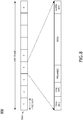
- FIG. 8 is a diagram of a TDMA scheme 800, in accordance with one or more embodiments of this disclosure.
- TDMA allows multiple transmissions (e.g., from one or more users) to be transmitted within one channel over the same period of time by dividing the time available for transmission into different time slots 810 that are organized within frames and dividing up a transmission to fit within each time slot 810.
- Each transmission in each data slot contains messaging data that is intended to be transmitted as well as control data (e.g., trail bits, synchronize bits, preamble, and guard data).
- Incorporated into the control data are instructions to the receiving node (e.g., relay node 116 and/or destination node 112) on how to encode and/or retransmit the data.
- the receiving node e.g., relay node 116 and/or destination node 112
- the relay nodes within the communication system 100 are configured to receive and retransmit TDMA transmissions.
- the relay nodes 116 are configured to transmit information to the destination node 112 using Space Time Block Codes (STBC).
- STBC Space Time Block Codes
- Alamouti STBC may be implemented within the communication system 100.
- Other STBC codes may be implemented as well including but not limited to QOSTBC and OSTBC (e.g., real OSTBC, complex OSTBC, generalized real OSTBC and generalized complex OSTBC).
- space time frequency block coding STFBC
- STFBC space time frequency block coding
- fixed-site environments like HFGCS that support split-site operation e.g., the transmit site and receive site are separated geographically to support full duplex communication
- MISO processing techniques like beamforming to improve communication performance
- the communication system 100 is configured to increase packet completion rates in time-diversity schemes (e.g., such as in point-to-point communications using STANAG 5066 protocols) through coding optimization, time slot optimization, and/or repeating slot data in one or more slots of the same TDMA frame.
- time-diversity schemes e.g., such as in point-to-point communications using STANAG 5066 protocols
- HF file transfer applications like STANAG 5066 generally set the SNR threshold to achieve 65% to 75% packet completion rates, as data is transmitted at a higher data rate that can be sustained by the available SNR.
- legacy HF and WBHF schemes that use STANAG 5066 typically use long preambles (e.g., approximately 240 ms) and robust coding (e.g., 1 ⁇ 2 to 1/8 th ) to aid channel estimation.
- long preambles e.g., approximately 240 ms
- robust coding e.g., 1 ⁇ 2 to 1/8 th
- a 3 MHz BPSK mode with a symbol rate of 2400 sps can deliver 105 bps (e.g., 150 bps assuming a slot completion rate of 70%).
- fades exceeding 20 dB are uncommon (e.g., less than a 10% probability and 75% of the fades are between 300 ms and one second long.
- a data delivery rate of 185 bps was achieved (e.g., 320 bps with a slot completion rate of 58%).
- the slot completion rate increased to 71% and an equivalent transfer rate to 113 bps.
- slot completion rates are achieved. Repeating the same information more than twice increases packet completion rates, but results in bit rates below 105 bps.
- embodiments of the methods disclosed herein may include one or more of the steps described herein. Further, such steps may be carried out in any desired order and two or more of the steps may be carried out simultaneously with one another. Two or more of the steps disclosed herein may be combined in a single step, and in some embodiments, one or more of the steps may be carried out as two or more sub-steps. Further, other steps or sub-steps may be carried in addition to, or as substitutes to one or more of the steps disclosed herein.
Landscapes
- Engineering & Computer Science (AREA)
- Computer Networks & Wireless Communication (AREA)
- Signal Processing (AREA)
- Quality & Reliability (AREA)
- Mobile Radio Communication Systems (AREA)
Applications Claiming Priority (1)
| Application Number | Priority Date | Filing Date | Title |
|---|---|---|---|
| US16/747,335 US11490452B2 (en) | 2020-01-20 | 2020-01-20 | Ad-hoc HF time frequency diversity |
Publications (2)
| Publication Number | Publication Date |
|---|---|
| EP3855642A1 true EP3855642A1 (fr) | 2021-07-28 |
| EP3855642B1 EP3855642B1 (fr) | 2026-04-15 |
Family
ID=74205617
Family Applications (1)
| Application Number | Title | Priority Date | Filing Date |
|---|---|---|---|
| EP21152588.6A Active EP3855642B1 (fr) | 2020-01-20 | 2021-01-20 | Diversité des fréquences temporelles hf ad hoc |
Country Status (2)
| Country | Link |
|---|---|
| US (1) | US11490452B2 (fr) |
| EP (1) | EP3855642B1 (fr) |
Cited By (2)
| Publication number | Priority date | Publication date | Assignee | Title |
|---|---|---|---|---|
| EP4443749A1 (fr) * | 2023-04-04 | 2024-10-09 | Rockwell Collins, Inc. | Algorithme de sélection de fréquence pour communication hf résiliente |
| US12501339B2 (en) | 2023-04-04 | 2025-12-16 | Rockwell Collins, Inc. | Joint optimization of frequency and relay selection for resilient HF communication |
Families Citing this family (3)
| Publication number | Priority date | Publication date | Assignee | Title |
|---|---|---|---|---|
| FR3121305A1 (fr) * | 2021-03-26 | 2022-09-30 | Orange | Procédé de contrôle d’une transmission multi-sauts dans un réseau de communication sans fil, procédé de traitement d’une transmission multi-sauts, dispositifs, système et programmes d’ordinateur correspondants. |
| FR3121306A1 (fr) * | 2021-03-26 | 2022-09-30 | Orange | Procédé de contrôle d’une transmission multi-sauts dans un réseau de communication sans fil, procédé de traitement d’une transmission multi-sauts, dispositifs, équipement relais, équipement de communication, équipement source, système et programmes d’ordinateur correspondants. |
| CN114827992B (zh) * | 2022-03-10 | 2024-09-06 | 西安电子科技大学 | 一种全双工miso物理层安全传输方法、系统及应用 |
Citations (5)
| Publication number | Priority date | Publication date | Assignee | Title |
|---|---|---|---|---|
| US20080175183A1 (en) * | 2007-01-22 | 2008-07-24 | Natasha Devroye | Asymmetric Cooperation in Downlink Cellular Networks with Relay stations |
| US20140098718A1 (en) * | 2012-10-04 | 2014-04-10 | Harris Corporation | Wireless communications system including single channel retransmission and related methods |
| US9282500B1 (en) | 2014-06-17 | 2016-03-08 | Rockwell Collins, Inc. | Ad hoc high frequency with advanced automatic link establishment system and related method |
| US10116382B1 (en) | 2017-02-24 | 2018-10-30 | Rockwell Collins, Inc. | Ad hoc high frequency network |
| WO2019070842A2 (fr) * | 2017-10-04 | 2019-04-11 | Skywave Networks Llc | Technique de sélection de la meilleure fréquence pour une transmission basée sur des conditions atmosphériques changeantes |
Family Cites Families (15)
| Publication number | Priority date | Publication date | Assignee | Title |
|---|---|---|---|---|
| US8089887B2 (en) | 2002-11-19 | 2012-01-03 | Massachusetts Institute Of Technology | Method for automatic signal routing in ad hoc networks |
| US7626966B1 (en) | 2005-01-06 | 2009-12-01 | Idealab | Ad hoc wireless communication system |
| US20060209892A1 (en) * | 2005-03-15 | 2006-09-21 | Radiospire Networks, Inc. | System, method and apparatus for wirelessly providing a display data channel between a generalized content source and a generalized content sink |
| US8139624B1 (en) | 2005-08-25 | 2012-03-20 | Rockwell Collins, Inc. | System and method for providing multiple ad hoc communication networks on a hardware channel |
| WO2008022175A2 (fr) | 2006-08-15 | 2008-02-21 | Comhouse Wireless Lp | Protocole de commande d'accès au support à arbitrage entre de nœuds pour des réseaux de diffusion ad hoc transportant une information éphémère |
| US8976727B2 (en) * | 2006-10-22 | 2015-03-10 | Viasat, Inc. | Cyclical obstruction communication system |
| US7746822B2 (en) * | 2007-03-29 | 2010-06-29 | Intel Corporation | Dynamic multi-access relaying for wireless networks |
| US20100232326A1 (en) | 2009-03-10 | 2010-09-16 | Harris Corporation, Corporation Of The State Of Delaware | Mobile ad-hoc network having interference mitigation and related methods |
| IL216282A (en) | 2011-11-10 | 2015-05-31 | Rafael Advanced Defense Sys | Mobile ad hoc network |
| FR2983668B1 (fr) | 2011-12-02 | 2014-06-27 | Thales Sa | Procede de communication dans un reseau ad hoc, station emettrice/receptrice et programme d'ordinateur associes |
| US9778368B2 (en) * | 2014-09-07 | 2017-10-03 | Trimble Inc. | Satellite navigation using side by side antennas |
| US20160197669A1 (en) * | 2014-12-11 | 2016-07-07 | Tesla Wireless Company LLC | Communication method and system that uses low latency/low data bandwidth and high latency/high data bandwidth pathways |
| CN115987342A (zh) * | 2016-08-10 | 2023-04-18 | Idac控股公司 | 用于上行链路(ul)信道相互性的方法、装置、系统和过程 |
| US10425148B2 (en) * | 2017-04-02 | 2019-09-24 | Parviz Jalali | Wireless communications system for broadband access to aerial platforms |
| US20210007008A1 (en) * | 2019-07-05 | 2021-01-07 | Huawei Technologies Co., Ltd. | Method and apparatus for data segmentation and reassembly over multiple wireless links |
-
2020
- 2020-01-20 US US16/747,335 patent/US11490452B2/en active Active
-
2021
- 2021-01-20 EP EP21152588.6A patent/EP3855642B1/fr active Active
Patent Citations (5)
| Publication number | Priority date | Publication date | Assignee | Title |
|---|---|---|---|---|
| US20080175183A1 (en) * | 2007-01-22 | 2008-07-24 | Natasha Devroye | Asymmetric Cooperation in Downlink Cellular Networks with Relay stations |
| US20140098718A1 (en) * | 2012-10-04 | 2014-04-10 | Harris Corporation | Wireless communications system including single channel retransmission and related methods |
| US9282500B1 (en) | 2014-06-17 | 2016-03-08 | Rockwell Collins, Inc. | Ad hoc high frequency with advanced automatic link establishment system and related method |
| US10116382B1 (en) | 2017-02-24 | 2018-10-30 | Rockwell Collins, Inc. | Ad hoc high frequency network |
| WO2019070842A2 (fr) * | 2017-10-04 | 2019-04-11 | Skywave Networks Llc | Technique de sélection de la meilleure fréquence pour une transmission basée sur des conditions atmosphériques changeantes |
Cited By (3)
| Publication number | Priority date | Publication date | Assignee | Title |
|---|---|---|---|---|
| EP4443749A1 (fr) * | 2023-04-04 | 2024-10-09 | Rockwell Collins, Inc. | Algorithme de sélection de fréquence pour communication hf résiliente |
| US12388480B2 (en) | 2023-04-04 | 2025-08-12 | Rockwell Collins, Inc. | Frequency selection algorithm for resilient HF communication |
| US12501339B2 (en) | 2023-04-04 | 2025-12-16 | Rockwell Collins, Inc. | Joint optimization of frequency and relay selection for resilient HF communication |
Also Published As
| Publication number | Publication date |
|---|---|
| US20210227626A1 (en) | 2021-07-22 |
| US11490452B2 (en) | 2022-11-01 |
| EP3855642B1 (fr) | 2026-04-15 |
Similar Documents
| Publication | Publication Date | Title |
|---|---|---|
| EP3855642B1 (fr) | Diversité des fréquences temporelles hf ad hoc | |
| US11757604B2 (en) | Distributed collaborative signaling in full duplex wireless transceivers | |
| Zlatanov et al. | Buffer-aided cooperative communications: opportunities and challenges | |
| US20090116419A1 (en) | Method and system of threshold selection for reliable relay stations grouping for downlink transmission | |
| US10396970B2 (en) | Adaptive relay schemes and virtual full-duplex relay operation | |
| Serror et al. | Channel coding versus cooperative ARQ: Reducing outage probability in ultra-low latency wireless communications | |
| KR101441431B1 (ko) | 메시지 중계 방법 및 시스템, 인코더 및 디코더 | |
| Schellmann et al. | Ultra-reliable V2X communication: On the value of user cooperation in the sidelink | |
| KR20060047562A (ko) | 양방향 무선 통신 방법 및 양방향 무선 통신 장치 | |
| EP4205440A1 (fr) | Procédés et systèmes d'accès à multiplexage par répartition dans le temps à canaux multiples | |
| Laghari et al. | Towards enabling multihop wireless local area networks for disaster communications | |
| Zhou et al. | Alternate distributed beamforming for decode-and-forward multi-relay systems using buffers | |
| Yang et al. | Outage performance of orthogonal space–time block codes transmission in opportunistic decode-and-forward cooperative networks with incremental relaying | |
| KR101434702B1 (ko) | 노드 사이의 메시지 전달 방법, 노드의 네트워크를 통한 메시지 중계 시스템, 통신 네트워크를 통한 메시지 중계 방법, 통신 네트워크를 통한 메시지 중계 시스템, 인코더 및 디코더 | |
| KR101511782B1 (ko) | 다중중계국기반 협력 무선통신시스템에서의 적응적 다이버시티 기법 및 이를 지원하는 장치 | |
| Le et al. | Analyses of transmit antenna selection to enhance security performance in cooperative radio communication networks under wiretap channel | |
| Sultan et al. | Buffered-relay selection in an underlay cognitive radio network | |
| Zhang et al. | Cooperative diversity for virtual MIMO system in geometry-based stochastic channel model | |
| Akram et al. | Performance analysis & latency calculation of cooperative communication protocols | |
| Dritsoula et al. | On the throughput potential of two-dimensional wireless multi-hop networks using directional antennas | |
| Yao et al. | A novel rateless coded protocol for half-duplex relaying systems with buffered relay | |
| Dong et al. | Maximum throughput adaptive rate transmission scheme for multihop diversity aided multihop links | |
| Kim | Throughput and delay performance with a cooperative retransmission scheme using distributed beamforming | |
| Zhou et al. | Achieving Resilient Communication for Self-Organizing Satellite Networks under Critical Conditions | |
| Mittal et al. | A cooperative spectrum sharing protocol for cognitive two-way AF relaying system |
Legal Events
| Date | Code | Title | Description |
|---|---|---|---|
| PUAI | Public reference made under article 153(3) epc to a published international application that has entered the european phase |
Free format text: ORIGINAL CODE: 0009012 |
|
| STAA | Information on the status of an ep patent application or granted ep patent |
Free format text: STATUS: THE APPLICATION HAS BEEN PUBLISHED |
|
| AK | Designated contracting states |
Kind code of ref document: A1 Designated state(s): AL AT BE BG CH CY CZ DE DK EE ES FI FR GB GR HR HU IE IS IT LI LT LU LV MC MK MT NL NO PL PT RO RS SE SI SK SM TR |
|
| STAA | Information on the status of an ep patent application or granted ep patent |
Free format text: STATUS: REQUEST FOR EXAMINATION WAS MADE |
|
| 17P | Request for examination filed |
Effective date: 20220128 |
|
| RBV | Designated contracting states (corrected) |
Designated state(s): AL AT BE BG CH CY CZ DE DK EE ES FI FR GB GR HR HU IE IS IT LI LT LU LV MC MK MT NL NO PL PT RO RS SE SI SK SM TR |
|
| STAA | Information on the status of an ep patent application or granted ep patent |
Free format text: STATUS: EXAMINATION IS IN PROGRESS |
|
| 17Q | First examination report despatched |
Effective date: 20230720 |
|
| GRAP | Despatch of communication of intention to grant a patent |
Free format text: ORIGINAL CODE: EPIDOSNIGR1 |
|
| STAA | Information on the status of an ep patent application or granted ep patent |
Free format text: STATUS: GRANT OF PATENT IS INTENDED |
|
| INTG | Intention to grant announced |
Effective date: 20260105 |
|
| GRAS | Grant fee paid |
Free format text: ORIGINAL CODE: EPIDOSNIGR3 |
|
| GRAA | (expected) grant |
Free format text: ORIGINAL CODE: 0009210 |
|
| STAA | Information on the status of an ep patent application or granted ep patent |
Free format text: STATUS: THE PATENT HAS BEEN GRANTED |
|
| AK | Designated contracting states |
Kind code of ref document: B1 Designated state(s): AL AT BE BG CH CY CZ DE DK EE ES FI FR GB GR HR HU IE IS IT LI LT LU LV MC MK MT NL NO PL PT RO RS SE SI SK SM TR |
|
| REG | Reference to a national code |
Ref country code: CH Ref legal event code: F10 Free format text: ST27 STATUS EVENT CODE: U-0-0-F10-F00 (AS PROVIDED BY THE NATIONAL OFFICE) Effective date: 20260415 |