EP3855811A1 - Verfahren und vorrichtung zur schätzung von pfadverlust zwischen endgeräten in einem drahtlosen kommunikationssystem - Google Patents
Verfahren und vorrichtung zur schätzung von pfadverlust zwischen endgeräten in einem drahtlosen kommunikationssystem Download PDFInfo
- Publication number
- EP3855811A1 EP3855811A1 EP19867813.8A EP19867813A EP3855811A1 EP 3855811 A1 EP3855811 A1 EP 3855811A1 EP 19867813 A EP19867813 A EP 19867813A EP 3855811 A1 EP3855811 A1 EP 3855811A1
- Authority
- EP
- European Patent Office
- Prior art keywords
- path loss
- transmission
- signal
- loss estimation
- reception
- Prior art date
- Legal status (The legal status is an assumption and is not a legal conclusion. Google has not performed a legal analysis and makes no representation as to the accuracy of the status listed.)
- Pending
Links
Images









Classifications
-
- H—ELECTRICITY
- H04—ELECTRIC COMMUNICATION TECHNIQUE
- H04W—WIRELESS COMMUNICATION NETWORKS
- H04W24/00—Supervisory, monitoring or testing arrangements
- H04W24/08—Testing, supervising or monitoring using real traffic
-
- H—ELECTRICITY
- H04—ELECTRIC COMMUNICATION TECHNIQUE
- H04W—WIRELESS COMMUNICATION NETWORKS
- H04W52/00—Power management, e.g. Transmission Power Control [TPC] or power classes
- H04W52/04—Transmission power control [TPC]
- H04W52/18—TPC being performed according to specific parameters
- H04W52/24—TPC being performed according to specific parameters using SIR [Signal to Interference Ratio] or other wireless path parameters
- H04W52/242—TPC being performed according to specific parameters using SIR [Signal to Interference Ratio] or other wireless path parameters taking into account path loss
-
- H—ELECTRICITY
- H04—ELECTRIC COMMUNICATION TECHNIQUE
- H04L—TRANSMISSION OF DIGITAL INFORMATION, e.g. TELEGRAPHIC COMMUNICATION
- H04L5/00—Arrangements affording multiple use of the transmission path
- H04L5/003—Arrangements for allocating sub-channels of the transmission path
- H04L5/0048—Allocation of pilot signals, i.e. of signals known to the receiver
- H04L5/0051—Allocation of pilot signals, i.e. of signals known to the receiver of dedicated pilots, i.e. pilots destined for a single user or terminal
-
- H—ELECTRICITY
- H04—ELECTRIC COMMUNICATION TECHNIQUE
- H04W—WIRELESS COMMUNICATION NETWORKS
- H04W24/00—Supervisory, monitoring or testing arrangements
- H04W24/10—Scheduling measurement reports ; Arrangements for measurement reports
-
- H—ELECTRICITY
- H04—ELECTRIC COMMUNICATION TECHNIQUE
- H04W—WIRELESS COMMUNICATION NETWORKS
- H04W52/00—Power management, e.g. Transmission Power Control [TPC] or power classes
- H04W52/04—Transmission power control [TPC]
- H04W52/18—TPC being performed according to specific parameters
- H04W52/24—TPC being performed according to specific parameters using SIR [Signal to Interference Ratio] or other wireless path parameters
- H04W52/245—TPC being performed according to specific parameters using SIR [Signal to Interference Ratio] or other wireless path parameters taking into account received signal strength
-
- H—ELECTRICITY
- H04—ELECTRIC COMMUNICATION TECHNIQUE
- H04W—WIRELESS COMMUNICATION NETWORKS
- H04W52/00—Power management, e.g. Transmission Power Control [TPC] or power classes
- H04W52/04—Transmission power control [TPC]
- H04W52/38—TPC being performed in particular situations
- H04W52/383—TPC being performed in particular situations power control in peer-to-peer links
-
- H—ELECTRICITY
- H04—ELECTRIC COMMUNICATION TECHNIQUE
- H04W—WIRELESS COMMUNICATION NETWORKS
- H04W56/00—Synchronisation arrangements
- H04W56/001—Synchronization between nodes
-
- H—ELECTRICITY
- H04—ELECTRIC COMMUNICATION TECHNIQUE
- H04W—WIRELESS COMMUNICATION NETWORKS
- H04W52/00—Power management, e.g. Transmission Power Control [TPC] or power classes
- H04W52/04—Transmission power control [TPC]
- H04W52/18—TPC being performed according to specific parameters
- H04W52/24—TPC being performed according to specific parameters using SIR [Signal to Interference Ratio] or other wireless path parameters
- H04W52/247—TPC being performed according to specific parameters using SIR [Signal to Interference Ratio] or other wireless path parameters where the output power of a terminal is based on a path parameter sent by another terminal
-
- H—ELECTRICITY
- H04—ELECTRIC COMMUNICATION TECHNIQUE
- H04W—WIRELESS COMMUNICATION NETWORKS
- H04W92/00—Interfaces specially adapted for wireless communication networks
- H04W92/16—Interfaces between hierarchically similar devices
- H04W92/18—Interfaces between hierarchically similar devices between terminal devices
Definitions
- the present disclosure relates to a method and apparatus for estimating inter-terminal sidelink path loss for transmission of control information and data information between terminals, and more particularly, to a method and apparatus for estimating path loss by using a signal for path loss estimation transmitted via a sidelink and controlling transmission power of the sidelink.
- 5G communication systems or pre-5G communication systems are called 'beyond 4G network communication systems' or'post long term evolution (LTE) systems'.
- 5G communication systems defined by the 3 rd generation partnership project (3GPP) are called new radio (NR) systems.
- 3GPP 3 rd generation partnership project
- NR new radio
- 5G communication systems In order to reduce the path loss of radio waves and increase a transmission distance of radio waves in ultra-high frequency bands, for 5G communication systems, technologies such as beamforming, massive multiple-input multiple-output (MIMO), full dimensional MIMO (FD-MIMO), array antenna, analog beamforming, and large scale antenna have been discussed, and have been applied to NR systems. Also, in order to improve system networks, for 5G communication systems, technologies such as evolved small cell, advanced small cell, cloud radio access network (cloud RAN), ultra-dense network, device-to-device (D2D) communication, wireless backhaul, moving network, cooperative communication, coordinated multi-points (CoMP), and interference cancellation have been developed.
- cloud RAN cloud radio access network
- D2D device-to-device
- CoMP coordinated multi-points
- ACM advanced coding modulation
- FQAM quadrature amplitude modulation
- SWSC sliding window superposition coding
- FBMC filter-bank multi-carrier
- NOMA non-orthogonal multiple access
- SCMA sparse code multiple access
- the Internet is evolving from a human-centered connection network through which humans create and consume information to an Internet of Things (loT) network through which distributed elements such as objects exchange and process information.
- Internet of Everything (loE) technology which is a combination of loT technology and big data processing technology through connection with a cloud server, is also emerging.
- technology elements such as sensing technology, wired/wireless communication and network infrastructure, service interface technology, and security technology are required, and thus technology for inter-object connection, such as sensor network, machine to machine (M2M) communication, or machine-type communication (MTC), has recently been studied.
- M2M machine to machine
- MTC machine-type communication
- intelligent Internet technology (IT) services that collect and analyze data generated by connected objects and create new value in human life may be provided.
- the loT may be applied to fields such as smart homes, smart buildings, smart cities, smart cars or connected cars, smart grids, health care, smart home appliances, and advanced medical services through convergence and integration of existing information technology (IT) and various industries.
- 5G communication systems to loT networks.
- technologies such as sensor network, M2M communication, and MTC are implemented by 5G communication technologies such as beamforming, MIMO, and array antenna.
- 5G communication technologies such as beamforming, MIMO, and array antenna.
- the application of a cloud RAN as big data processing technology may also be considered as an example of convergence between 5G technology and loT technology.
- V2X vehicle-to-everything
- D2D device-to-device
- V2X based on 5G or NR systems may support unicast communication, groupcast (or multicast) communication, broadcast communication, etc., between terminals.
- V2X based on 5G or NR systems aims at providing more advanced services such as platooning, advanced driving, extended sensor, and remote driving.
- V2X based on 5G or NR systems needs to support link adaptation based on measurement of the quality of a sidelink between terminals.
- Disclosed embodiments provide a method and apparatus for estimating inter-terminal sidelink path loss, to support high reliability and a high data rate.
- disclosed embodiments provide a method and apparatus for controlling inter-terminal sidelink transmission power according to path loss estimation.
- disclosed embodiments provide a method and apparatus for effectively providing a service in a mobile communication system.
- a path loss estimation method of a transmission terminal in a mobile communication system may include transmitting a signal for path loss estimation to a reception terminal, receiving a path loss estimation result report from the reception terminal in response to the signal for path loss estimation, configuring a transmission power based on the path loss estimation result report, and performing a sidelink transmission with the reception terminal with the configured transmission power.
- a path loss estimation method of a reception terminal in a wireless communication system may include receiving a signal for path loss estimation from a transmission terminal, measuring reference signal received power (RSRP) based on the signal for path loss estimation, and transmitting a path loss estimation result report including the RSRP to the transmission terminal.
- RSRP reference signal received power
- a transmission terminal may include a transceiver, a memory storing a path loss estimation method program and data of the transmission terminal, and a processor configured to execute the program stored in the memory to transmit a signal for path loss estimation to a reception terminal, receive a path loss estimation result report from the reception terminal in response to the signal for path loss estimation, configure transmission power based on the path loss estimation result report, and perform sidelink transmission with the reception terminal with the configured transmission power.
- a reception terminal may include a transceiver, a memory storing a path loss estimation method program and data of the reception terminal, and a processor configured to execute the program stored in the memory to receive a signal for path loss estimation from a transmission terminal, measure reference signal received power (RSRP) based on the signal for path loss estimation, and transmit a path loss estimation result report including the RSRP to the transmission terminal.
- RSRP reference signal received power
- transmission parameters of sidelink control information and data information may be adjusted according to channel quality of a sidelink. Accordingly, the reliability and a data rate of the sidelink control information and the data information in a vehicle communication system, a D2D system, etc. may be improved. Also, the amount of interference caused by a nearby cell or vehicle may be reduced. Accordingly, more efficient communication between terminals may be supported. Furthermore, a service may be effectively provided in a mobile communication system.
- a path loss estimation method of a transmission terminal in a mobile communication system may include transmitting a signal for path loss estimation to a reception terminal, receiving a path loss estimation result report from the reception terminal in response to the signal for path loss estimation, configuring transmission power based on the path loss estimation result report, and performing sidelink transmission with the reception terminal with the configured transmission power.
- the path loss estimation result report may include at least one layer 1 reference signal received power (L1-RSRP) measured by the reception terminal, wherein the receiving of the path loss estimation result report from the reception terminal in response to the signal for path loss estimation includes receiving the at least one L1-RSRP measured by the reception terminal via a sidelink feedback channel (physical sidelink feedback channel (PSFCH)) or a medium access control control element (MAC CE) transmitted via a sidelink data channel (physical sidelink shared channel (PSSCH)).
- L1-RSRP layer 1 reference signal received power
- the MAC CE may include the at least one L1-RSRP, wherein, when the MAC CE includes a plurality of L1-RSRPs, the MAC CE includes a user equipment (UE) ID.
- UE user equipment
- the path loss estimation result report may include layer 3 RSRP (L3-RSRP) measured by the reception terminal, wherein the receiving of the path loss estimation result report from the reception terminal in response to the signal for path loss estimation includes receiving the L3-RSRP measured by the reception terminal through a radio resource control (RRC) message transmitted via a sidelink data channel (PSSCH).
- RRC radio resource control
- the receiving of the path loss estimation result report from the reception terminal in response to the signal for path loss estimation may include receiving the path loss estimation result report after the signal for path loss estimation is transmitted to the reception terminal, before a pre-configured timer expires, or during a pre-configured second time before, after, or before and after a point of time when a pre-configured first time has elapsed or a point of time when a pre-configured number of slots are received.
- the path loss estimation method may further include transmitting, to the reception terminal, information indicating that the path loss estimation result report has not been received.
- the signal for path loss estimation may include at least one signal from among a sidelink synchronization signal including at least one of a primary sidelink synchronization signal (PSSS) and a secondary sidelink synchronization signal (SSSS), a demodulation reference signal (DMRS) transmitted via at least one of a sidelink broadcast channel (physical sidelink broadcast channel (PSBCH)), a sidelink control channel (physical sidelink control channel (PSCCH)), and a sidelink data channel (physical sidelink shared channel (PSSCH)), and a reference signal for supporting a sidelink operation.
- a sidelink synchronization signal including at least one of a primary sidelink synchronization signal (PSSS) and a secondary sidelink synchronization signal (SSSS), a demodulation reference signal (DMRS) transmitted via at least one of a sidelink broadcast channel (physical sidelink broadcast channel (PSBCH)), a sidelink control channel (physical sidelink control channel (PSCCH)), and a sidelink data channel (physical sidelink shared channel (PSSCH)
- the transmitting of the signal for path loss estimation to the reception terminal may include transmitting the signal for path loss estimation to the reception terminal, in at least one case from among a case where a command for transmission of the signal for path loss estimation is received from a base station, a case where reference signal received power (RSRP) measured by the transmission terminal for a signal for downlink path loss estimation transmitted by the base station is equal to or greater than a configured threshold value or equal to or less than a configured threshold value, a case where the transmission terminal determines that the signal for path loss estimation needs to be transmitted, and a case where a transmission request signal of the signal for path loss estimation is received from the reception terminal.
- RSRP reference signal received power
- the transmitting of the signal for path loss estimation to the reception terminal may include configuring, as transmission power of the signal for path loss estimation, at least one from among pre-configured transmission power, maximum transmission power of the transmission terminal, transmission power according to configuration of the base station, transmission power determined based on RSRP measured by the transmission terminal for a signal for downlink path loss estimation transmitted by the base station, and transmission power determined based on RSRP measured by the transmission terminal for a transmission request signal of the signal for path loss estimation received from the reception terminal.
- the receiving of the path loss estimation result report from the reception terminal in response to the signal for path loss estimation may include receiving the path loss estimation result report periodically or aperiodically according to at least one of configuration of a base station and sidelink control information.
- the path loss estimation method may further include transmitting, to the reception terminal, information on the transmission power of the signal for path loss estimation including at least one of offset information between a configured reference signal and a transmission power value of the signal for path loss estimation and the transmission power value of the signal for path loss estimation.
- the signal for path loss estimation and the information on the transmission power of the signal for path loss estimation may be transmitted via the same channel or different channels.
- the performing of the sidelink transmission with the reception terminal with the configured transmission power may include transmitting at least one of sidelink control information and sidelink data to the reception terminal.
- a path loss estimation method of a reception terminal in a wireless communication system may include receiving a signal for path loss estimation from a transmission terminal, measuring reference signal received power (RSRP) based on the signal for path loss estimation, and transmitting a path loss estimation result report including the RSRP to the transmission terminal.
- RSRP reference signal received power
- the RSRP may include at least one layer 1 RSRP (L1-RSRP), wherein the transmitting of the path loss estimation result report including the RSRP to the transmission terminal includes transmitting the at least one L1-RSRP via a sidelink feedback channel (physical sidelink feedback channel (PSFCH)) or a medium access control control element (MAC CE) transmitted via a sidelink data channel (physical sidelink shared channel (PSSCH)).
- L1-RSRP layer 1 RSRP
- PSFCH physical sidelink feedback channel
- MAC CE medium access control control element
- the MAC CE may include the at least one L1-RSRP, wherein, when the MAC CE includes a plurality of L1-RSRPs, the MAC CE includes a user equipment (UE) ID.
- UE user equipment
- the transmitting of the path loss estimation result report including the RSRP to the transmission terminal may include transmitting the L1-RSRP every pre-configured time or every pre-configured slots, after the signal for path loss estimation is received, until a pre-configured timer expires, or until a reporting stop command is received from the transmission terminal.
- the path loss estimation method may further include re-configuring the timer.
- the path loss estimation result report may include layer 3 RSRP (L3-RSRP), wherein the transmitting of the path loss estimation result report including the RSRP to the transmission terminal includes transmitting the L3-RSRP through a radio resource control (RRC) message transmitted via a sidelink data channel (physical sidelink shared channel (PSSCH)).
- RRC radio resource control
- the signal for path loss estimation may include at least one signal from among a sidelink synchronization signal including at least one of a primary sidelink synchronization signal (PSSS) and a secondary sidelink synchronization signal (SSSS), a demodulation reference signal (DMRS) transmitted via at least one of a sidelink broadcast channel (physical sidelink broadcast channel (PSBCH)), a sidelink control channel (physical sidelink control channel (PSCCH)), and a sidelink data channel (physical sidelink shared channel (PSSCH)), and a reference signal for supporting a sidelink operation.
- a sidelink synchronization signal including at least one of a primary sidelink synchronization signal (PSSS) and a secondary sidelink synchronization signal (SSSS), a demodulation reference signal (DMRS) transmitted via at least one of a sidelink broadcast channel (physical sidelink broadcast channel (PSBCH)), a sidelink control channel (physical sidelink control channel (PSCCH)), and a sidelink data channel (physical sidelink shared channel (PSSCH)
- the transmitting of the path loss estimation result report including the RSRP to the transmission terminal may include transmitting the path loss estimation result report periodically or aperiodically according to at least one of configuration of a base station and sidelink control information.
- the measuring of the RSRP based on the signal for path loss estimation may include measuring pre-configured transmission power, maximum transmission power of the reception terminal, transmission power according to configuration of a base station, and the RSRP for a signal for downlink path loss estimation transmitted by the base station.
- the path loss estimation method may further include receiving information on transmission power of the signal for path loss estimation including at least one of offset information between a configured reference signal and a transmission power value of the signal for path loss estimation and the transmission power value of the signal for path loss estimation.
- the signal for path loss estimation and the information on the transmission power of the signal for path loss estimation may be received via the same channel or different channels.
- a transmission terminal may include a transceiver, a memory storing a path loss estimation method program and data of the transmission terminal, and a process configured to execute the program stored in the memory to transmit a signal for path loss estimation to a reception terminal, receive a path loss estimation result report from the reception terminal in response to the signal for path loss estimation, configure transmission power based on the path loss estimation result report, and perform sidelink transmission with the reception terminal with the configured transmission power.
- a reception terminal may include a transceiver, a memory storing a path loss estimation method program and data of the reception terminal, and a processor configured to execute the program stored in the memory to receive a signal for path loss estimation from a transmission terminal, measure reference signal received power (RSRP) based on the signal for path loss estimation, and transmit a path loss estimation result report including the RSRP to the transmission terminal.
- RSRP reference signal received power
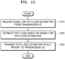
- a path loss estimation method of a transmission terminal in a wireless communication system may include receiving a signal for path loss estimation from a reception terminal, estimating a path loss based on the signal for path loss estimation, configuring transmission power based on the path loss estimation result, and performing sidelink transmission with the reception terminal with the configured transmission power.
- the signal for path loss estimation may include at least one from among a sidelink synchronization signal including at least one of a primary sidelink synchronization signal (PSSS) and a secondary sidelink synchronization signal (SSSS), a demodulation reference signal (DMRS) transmitted via at least one of a sidelink broadcast channel (physical sidelink broadcast channel (PSBCH)), a sidelink control channel (physical sidelink control channel (PSCCH)), and a sidelink data channel (physical sidelink shared channel (PSSCH)), and a reference signal for supporting a sidelink operation.
- a sidelink synchronization signal including at least one of a primary sidelink synchronization signal (PSSS) and a secondary sidelink synchronization signal (SSSS), a demodulation reference signal (DMRS) transmitted via at least one of a sidelink broadcast channel (physical sidelink broadcast channel (PSBCH)), a sidelink control channel (physical sidelink control channel (PSCCH)), and a sidelink data channel (physical sidelink shared channel (PSSCH)
- DMRS
- the path loss estimation method may further include transmitting a transmission request signal of the signal for path loss estimation to the reception terminal, in at least one case from among a case where a command for a transmission request of the signal for path loss estimation is received from a base station, a case where reference signal received power (RSRP) measured by the transmission terminal for a signal for sidelink path loss estimation transmitted by the base station is equal to or greater than a configured threshold value or equal to or less than a configured threshold value, and a case where the transmission terminal determines that the signal for path loss estimation needs to be transmitted.
- RSRP reference signal received power
- the transmitting of the transmission request signal of the signal for path loss estimation to the reception terminal may include configuring, as transmission power of the transmission request signal of the signal for path loss estimation, at least one of pre-configured transmission power, maximum transmission power of the transmission terminal, transmission power according to configuration of a base station, and transmission power determined based on RSRP measured by the transmission terminal for a signal for downlink path loss estimation transmitted by the base station.
- the path loss estimation method may further include receiving information on transmission power of the signal for path loss estimation including at least one of offset information between a configured reference signal and a transmission power value of the signal for path loss estimation and the transmission power value of the signal for path loss estimation.
- the signal for path loss estimation and the information on the transmission power of the signal for path loss estimation may be received via the same channel or different channels.
- a path loss estimation method of a reception terminal in a wireless communication system may include transmitting a signal for path loss estimation to a transmission terminal and performing sidelink transmission with the transmission terminal.
- the signal for path loss estimation may include at least one signal from among a sidelink synchronization signal including at least one of a primary sidelink synchronization signal (PSSS) and a secondary sidelink synchronization signal (SSSS), a demodulation reference signal (DMRS) transmitted via at least one of a sidelink broadcast channel (physical sidelink broadcast channel (PSBCH)), a sidelink control channel (physical sidelink control channel (PSCCH)), and a sidelink data channel (physical sidelink shared channel (PSSCH)), and a reference signal for supporting a sidelink operation.
- a sidelink synchronization signal including at least one of a primary sidelink synchronization signal (PSSS) and a secondary sidelink synchronization signal (SSSS), a demodulation reference signal (DMRS) transmitted via at least one of a sidelink broadcast channel (physical sidelink broadcast channel (PSBCH)), a sidelink control channel (physical sidelink control channel (PSCCH)), and a sidelink data channel (physical sidelink shared channel (PSSCH)
- the transmitting of the signal for path loss estimation to the transmission terminal may include transmitting the signal for path loss estimation to the transmission terminal, in at least one case from among a case where a command for transmission of the signal for path loss estimation is received from a base station, a case where reference signal received power (RSRP) measured by the reception terminal for a signal for downlink path loss estimation transmitted by the base station is equal to or greater than a pre-configured threshold value or equal to or less than a configured threshold value, a case where the reception terminal determines that the signal for path loss estimation needs to be transmitted, and a case where a transmission request signal of the signal for path loss estimation is received from the transmission terminal.
- RSRP reference signal received power
- the transmitting of the signal for path loss estimation to the transmission terminal may include configuring, as transmission power of the signal for path loss estimation, at least one of pre-configured transmission power, maximum transmission power of the reception terminal, transmission power according to configuration of a base station, transmission power determined based on RSRP measured by the reception terminal for a signal for downlink path loss estimation transmitted by the base station, and transmission power determined based on RSRP measured by the reception terminal for a transmission request signal of the signal for path loss estimation received from the transmission terminal.
- the path loss estimation method may further include transmitting, to the transmission terminal, information on the transmission power of the signal for path loss estimation including at least one of offset information between a configured reference signal and a transmission power value of the signal for path loss estimation and the transmission power value of the signal for path loss estimation.
- the signal for path loss estimation and the information on the transmission power of the signal for path loss estimation may be transmitted via the same channel or different channels.
- the performing of the sidelink transmission with the transmission terminal may include receiving at least one of sidelink control information and sidelink data from the transmission terminal.
- a transmission terminal may include a transceiver, a memory storing a path loss estimation method program and data of the transmission terminal, and a processor configured to execute the program stored in the memory to receive a signal for path loss estimation from a reception terminal, estimate a path loss based on the signal for path loss estimation, configure transmission power based on a path loss estimation result, and perform sidelink transmission with the reception terminal with the configured transmission power.
- a reception terminal may include a transceiver, a memory storing a path loss estimation method program and data of the reception terminal, and a processor configured to execute the program stored in the memory to transmit a signal for path loss estimation to a transmission terminal and perform sidelink transmission with the transmission terminal.
- each block of flowchart illustrations and combinations of blocks in the flowchart illustrations may be implemented by computer program instructions. Because these computer program instructions may be loaded into a processor of a general-purpose computer, a special purpose computer, or a programmable data processing device, the instructions, which are executed via the processor of the computer or another programmable data processing device, generate means for implementing functions described in the flowchart block(s). Because these computer program instructions may also be stored in a computer-usable or computer-readable memory that may direct a computer or another programmable data processing device to function in a particular manner, the instructions stored in the computer-usable or computer-readable memory may produce manufacturing items including instruction means that implement the functions described in the flowchart block(s).
- the computer program instructions may also be loaded into a computer or another programmable data processing device, a series of operational steps may be performed on the computer or other programmable device to produce a computer implemented process, and thus the instructions executed on the computer or other programmable device may provide steps for implementing the functions described in the flowchart block(s).
- each block of the flowchart illustrations may represent a module, segment, or portion of code, which includes one or more executable instructions for implementing specified logical function(s). It should also be noted that in some alternative implementations, functions noted in blocks may occur out of order. For example, two blocks shown in succession may actually be executed substantially concurrently or the blocks may sometimes be executed in a reverse order, depending upon the functionality involved.
- the term ' ⁇ unit' used in the present embodiment refers to a software or hardware component, such as a field-programmable gate array (FPGA) or an application-specific integrated circuit (ASIC), which performs certain tasks.
- FPGA field-programmable gate array
- ASIC application-specific integrated circuit
- the term ' ⁇ unit' is not limited to software or hardware.
- the term'- unit' may be configured to be in an addressable storage medium or configured to operate one or more processors.
- ' ⁇ unit' may include, by way of example, components such as software components, object-oriented software components, class components, and task components, processes, functions, attributes, procedures, and subroutines, segments of program code, drivers, firmware, microcode, circuitry, data, databases, data structures, tables, arrays, and variables.
- components and ' ⁇ units' may be combined into fewer components and ' ⁇ units', or may be further separated into additional components and ' ⁇ units'. Further, components and ' ⁇ units' may be implemented to operate one or more central processing units (CPUs) in a device or a secure multimedia card. Also, a '- unit' in an embodiment may include one or more processors.
- CPUs central processing units
- a '- unit' in an embodiment may include one or more processors.
- the present disclosure uses terms and names defined in standards regarding 5 th generation (5G), new radio (NR), or long term evolution (LTE) systems.
- 5G 5 th generation
- NR new radio
- LTE long term evolution
- the present disclosure is not limited by such terms and names, and may be equally applied to systems complying with other standards.
- a transmission terminal does not refer a terminal that transmits a signal for path loss estimation, but refers to a terminal that transmits sidelink data and control information.
- a reception terminal does not refer to a terminal that receives a signal for path loss estimation, but refers to a terminal that receives sidelink data and control information.
- FIG. 1 is a view for describing a vehicle-to-everything (V2X) system to which a disclosed embodiment is applied.
- V2X vehicle-to-everything
- the uplink (UL) and the downlink (DL) with the base station gNB/eNB/RSU and the V2X UEs UE-1 and UE-2 may be referred to as Uu interfaces, and the sidelink (SL) between the V2X UEs UE-1 and UE-2 may be referred to as a PC5 interface. Accordingly, in the present disclosure, these terms may be used interchangeably.
- a UE may refer to a vehicle supporting vehicle-to-vehicle (V2V) communication, a vehicle or a handset of a pedestrian (e.g., a smartphone) supporting vehicle-to-pedestrian (V2P) communication, a vehicle supporting vehicle-to-network (V2N) communication, or a vehicle supporting vehicle-to-infrastructure (V2I) communication.
- the UE may refer to a road side unit (RSU) having a UE function, an RSU having a base station function, or an RSU having a part of the UE function and a part of the base station function.
- RSU road side unit
- FIG. 2 is a view for describing a V2X communication method performed through a sidelink.
- a transmission UE and a reception UE may perform one-to-one communication, which may be referred to as unicast communication.
- a transmission UE and a reception UE may perform one-to-many communication, which may be referred to as groupcast or multicast communication.
- UE-1, UE-2, and UE-3 perform groupcast communication by forming one group (group A)
- UE-4, UE-5, UE-6, and UE-7 perform groupcast communication by forming another group (group B).
- group A group A
- group B group B
- Each UE performs groupcast communication only in a group to which the UE belongs, and communication is not performed between different groups.
- two groups are formed in (b) of FIG. 2 , a greater number of groups may be formed without being limited to the illustration.
- V2X UEs may perform broadcast communication.
- all V2X UEs receive data and control information transmitted by a V2X transmission UE through a sidelink.
- the V2X UE UE-1 is a transmission UE for broadcast communication
- all UEs UE-2, UE-3, UE-4, UE-5, UE-6, and UE-7 may receive data and control information transmitted by the V2X UE UE-1.
- FIG. 3 is a diagram for describing a method by which a UE estimates a downlink path loss (PL) in an existing cellular system.
- PL downlink path loss
- a UE TX UE may receive a parameter configuration for estimating a downlink path loss and a signal for estimating a path loss from a base station eNB/gNB.
- the UE TX UE may receive a path loss signal transmitted by the base station eNB/gNB for downlink path loss estimation, may measure reference signal received power (RSRP), and may measure a downlink path loss by using [Equation 1].
- RSRP reference signal received power
- downlink path loss transmission power of base station signal ⁇ RSRP measured by UE
- transmission power of a base station signal may be transmission power of a signal for downlink path loss estimation transmitted by the base station, and a signaling method may vary according to a type of the signal.
- an estimation signal is a cell-specific reference signal (CRS)
- the transmission power of the base station signal may refer to transmission power of the CRS, and may be transmitted to the UE through a parameter referenceSignalPower of system information.
- the transmission power of the base station signal may refer to transmission power of a demodulation reference signal (DMRS) transmitted via a physical broadcast channel (PBCH) and a secondary synchronization signal (SSS), and may be transmitted to the UE through a parameter ss-PBCH-BlockPower of the system information.
- DMRS demodulation reference signal
- PBCH physical broadcast channel
- SSS secondary synchronization signal
- the base station may transmit information on transmission power of the CSI-RS to the UE through a parameter powerControlOffsetSS of UE dedicated RRC information.
- powerControlOffsetSS may refer to a transmission power difference (offset) between the CSI-RS and the SSB.
- the UE TX UE may configure a transmission power value of uplink data and control information based on an estimated downlink path loss value and may perform uplink transmission.
- FIG. 4 is a diagram for describing a method of estimating an inter-UE sidelink path loss, according to a disclosed embodiment.
- a base station eNB/gNB may be considered as a receiver that receives uplink data and control information from a UE. That is, the receiver (base station) may transmit a signal for path loss estimation and transmission power of the signal for path loss estimation to a transmitter (UE), and the transmitter (UE) may configure a transmission power value for uplink data and control information transmission based on a path loss value estimated by the transmitter (UE) and may perform uplink transmission to the receiver (base station).
- a reception (RX) UE may transmit a signal for sidelink path loss estimation and information on transmission power to a transmission (TX) UE, and the TX UE may estimate a sidelink path loss value by using the signal and the information.
- the RX UE may configure transmission power of sidelink data and control information based on the estimated path loss value, and may perform sidelink transmission to the TX UE.
- the RX UE may transmit a signal for path loss estimation and information on transmission power of the signal to the TX UE.
- the TX UE may receive the signal for path loss estimation, may measure RSRP, and may estimate a path loss by using [Equation 1].
- the TX UE may configure sidelink transmission power based on the estimated path loss value, and may transmit sidelink control information and data information to the RX UE.
- the RX UE may transmit a signal for path loss estimation in response to a request of the TX UE.
- the TX UE may transmit a request for transmission of a signal for path loss estimation to the RX UE, and the RX UE receiving the request may transmit the signal for path loss estimation to the TX UE.
- the RX UE may transmit information on transmission power of the signal for path loss estimation to the TX UE.
- the TX UE may measure RSRP through the signal for path loss estimation and may estimate a path loss by using [Equation 1].
- the TX UE may configure sidelink transmission power based on the estimated path loss value, and may transmit sidelink control information and data information to the RX UE.
- a TX UE does not refer to a UE that transmits a signal for path loss estimation, but refers to a UE that transmits sidelink data and control information.
- an RX UE does not refer to a UE that receives a signal for path loss estimation, but refers to a UE that receives sidelink data and control information.
- FIG. 5 is a diagram illustrating a method of estimating an inter-UE sidelink path loss, according to another disclosed embodiment.
- a TX UE transmits a signal for path loss estimation, and an RX UE estimates a path loss.
- a signal for path loss estimation transmitted by the TX UE may be transmitted without a request of the RX UE ((a) of FIG. 5 ), or may be transmitted in response to a request of the TX UE ((b) of FIG. 5 ).
- the TX UE may transmit a signal for path loss estimation to the RX UE and may transmit information on transmission power of the signal.
- the RX UE may measure RSRP by using the signal for path loss estimation and may estimate a path loss by using [Equation 1].
- the RX UE may report information on the path loss value estimated by the RX UE to the TX UE.
- the TX UE may configure sidelink transmission power based on the information on the path loss value reported from the RX UE, and may transmit sidelink control information and data information to the RX UE.
- the RX UE may transmit a request for transmission of a signal for path loss estimation to the TX UE, and the TX UE receiving the request may transmit the signal for path loss estimation to the RX UE.
- the TX UE may transmit information on transmission power of the signal for path loss estimation to the RX UE.
- the RX UE may measure RSRP through the signal for path loss estimation and may estimate a path loss by using [Equation 1].
- the RX UE may report information on the path loss value estimated by the RX UE to the TX UE.
- the TX UE may configure sidelink transmission power based on the information on the path loss value reported from the RX UE and may transmit sidelink control information and data information to the RX UE.
- a signal for path loss estimation described with reference to FIGS. 4 and 5 may include at least one of the following signals.
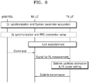
- FIG. 6 is a diagram for describing a method of transmitting and receiving a path loss measurement signal to estimate a sidelink path loss, according to a disclosed embodiment.
- FIG. 6 is a detailed diagram illustrating a process of (a) of FIG. 4 .
- a base station may be a base station that supports both V2X communication and general cellular communication, or a road side unit (RSU) that supports only V2X communication. Accordingly, unless otherwise specified in the present disclosure, the base station and the RSU may be used for the same concept and may be interchangeably used.
- RSU road side unit
- UL synchronization and RRC connection setup and command are each marked by a dashed line.
- a procedure or an operation marked by a dashed line may be an optional procedure or an optional operation. That is, a procedure or an operation marked by a dashed line may be performed or may not be performed. This is the same not only in FIG. 6 but also in other drawings below.
- V2X UEs in coverage of the base station may perform downlink synchronization and may obtain system information.
- the downlink synchronization may be performed through a primary synchronization signal/secondary synchronization signal (PSS/SSS) received from the base station, or may be performed through a synchronization signal received from a global navigation satellite system (GNSS).
- the V2X UEs performing the downlink synchronization may obtain system information related to V2X through a V2X dedicated system information block (SIB) transmitted by the base station gNB /RSU.
- the V2X UEs in the coverage may perform uplink synchronization through a random access procedure with the base station and may perform an RRC connection procedure.
- the uplink synchronization and the RRC connection procedure may be performed by only one of a transmission UE or a reception UE, or may be performed by both the transmission UE and the reception UE.
- Information on which UE from among the transmission UE and the reception UE is to perform the uplink synchronization and the RRC connection procedure may vary according to a transmission mode of sidelink control information/data information, a sidelink path loss estimation procedure, a signaling method, etc.
- a transmission mode of sidelink control information/data information For example, as shown in FIG. 6 , in a mode in which the base station transmits a command for transmission of a path loss signal to a V2X reception UE, the reception UE may have to perform the uplink synchronization and the RRC connection procedure with the base station.
- the transmission UE may have to perform the uplink synchronization and the RRC connection procedure with the base station.
- both the reception UE and the transmission UE may have to perform the uplink synchronization and the RRC connection procedure with the base station according to a signaling method.
- a command of the base station is transmitted to the V2X transmission UE and the V2X reception UE through downlink control information (DCI), a medium access control control element (MAC CE), or a UE dedicated RRC message
- DCI downlink control information
- MAC CE medium access control control element
- UE dedicated RRC message the V2X transmission UE and the V2X reception UE may perform the uplink synchronization and the RRC connection procedure with the base station.
- the V2X transmission UE and the V2X reception UE may not perform the uplink synchronization and the RRC connection procedure with the base station.
- a reception UE may refer to a UE that receives sidelink control information and data information
- a transmission UE may refer to a UE that transmits sidelink control information and data information. Accordingly, the reception UE and the transmission UE in FIG. 6 may not be related to transmission and reception of a path loss signal.
- a V2X transmission UE or a V2X reception UE performing downlink synchronization or uplink synchronization and RRC connection configuration with the base station may perform sidelink configuration for unicast communication.
- the unicast link configuration may be performed in a higher layer (e.g., an application layer), and as shown in FIG. 6 , the unicast link configuration may be performed between the V2X transmission UE that is to transmit V2X control information/data information in a unicast method and the V2X reception UE that is to receive the V2X control information/data information in the unicast method.
- the base station may engage in the unicast link configuration.
- the V2X transmission UE may transmit a request for the unicast link configuration to the base station, and the base station may transmit a response to the request to the V2X reception UE. Also, the base station may transmit a confirmation for the unicast link configuration to the V2X transmission UE and the V2X reception UE.
- the procedure may not be recognized by a physical layer and a MAC layer.
- the base station may transmit a command for transmission of a signal for path loss estimation to the V2X reception UE.
- the command of the base station may be transmitted to the V2X reception UE through UE-specific DCI (or group common DCI) for a sidelink or through a MAC CE or a UE-specific RRC message.
- the DCI may use a radio network temporary identifier (RNTI) different from UE-specific DCI or group common DCI used in existing cellular communication for distinguishment from existing cellular communication.
- RNTI radio network temporary identifier
- the V2X reception UE may transmit the signal for path loss estimation to the V2X transmission UE after unicast link configuration without the command of the base station.
- the V2X reception UE may start a timer at a point of time when a request for unicast link configuration is received from the base station or the V2X transmission UE or at a point of time when the unicast link configuration succeeds, and may transmit the signal for path loss estimation to the V2X transmission UE at a point of time when the timer expires.
- the V2X transmission UE may start a timer from a point of time when a request for unicast link configuration is transmitted or from a point of time when the unicast link configuration succeeds, and may expect to receive the signal for path loss estimation from the V2X reception UE at a point of time when the timer expires.
- the V2X reception UE may transmit the signal for path loss estimation after a certain period of time (e.g., after [x] subframes, [x] slots, or [x] ms) from a point of time when unicast link configuration succeeds.
- the V2X transmission UE may receive the signal for path loss estimation after a certain period of time (e.g., [x] subframes, [x] slots, or [x] ms) from a point of time when unicast link configuration succeeds.
- a certain period of time e.g., [x] subframes, [x] slots, or [x] ms
- the V2X reception UE transmits the signal for path loss estimation without the command of the base station
- an RSRP value measured by the V2X reception UE with the base station is equal to or greater than (or greater than) a specific threshold value configured by the base station or is equal to or less than (or less than) a specific threshold value
- the V2X reception UE may transmit the signal for path loss estimation to the V2X transmission UE.
- the base station may configure the RSRP threshold value in the V2X reception UE through a system transmission block for V2X (V2X SIB) or a UE-specific RRC/common RRC message for V2X.
- the V2X reception UE may transmit the signal for path loss estimation to the V2X transmission UE.
- the V2X reception UE satisfies a condition for the RSRP threshold value configured by the base station, when the base station sends a command for stopping transmitting the signal for path loss estimation, the V2X reception UE may stop transmitting the signal for path loss estimation.
- the V2X reception UE transmits the signal for path loss estimation without the command of the base station
- a modulation order of V2X data information received by the V2X reception UE is equal to or less than, or less than a certain level
- the V2X reception UE may transmit the signal for path loss estimation.
- the modulation order of the V2X data information received by the V2X reception UE is equal to or less than 16-quadrature amplitude modulation (QAM) (or is quadrature phase-shift keying (QPSK) less than 16-QAM
- the V2X reception UE may transmit the signal for path loss estimation to the V2X transmission UE.
- QAM quadrature phase-shift keying
- the V2X reception UE may transmit the signal for path loss estimation to the V2X transmission UE.
- TBS transport block
- the V2X reception UE may transmit the signal for path loss estimation to the V2X transmission UE.
- the V2X reception UE may transmit the signal for path loss estimation (e.g., when the aggregation level is equal to or greater than 8, or is equal to 16 that is greater than 8).
- the V2X reception UE transmits the signal for path loss estimation without the command of the base station to the V2X transmission UE
- an RSRP value of a sidelink channel previously measured by the V2X reception UE is equal to or greater than (or greater than) a specific threshold value configured by the base station, or is equal to or less than (or less than) a specific threshold value
- the V2X reception UE may transmit the signal for path loss estimation to the V2X transmission UE.
- the base station may configure the RSRP threshold value of the sidelink channel in the V2X reception UE through a system transmission block for V2X (V2X SIB) or a UE-specific RRC/common RRC message for V2X.
- the V2X reception UE may transmit the signal for path loss estimation to the V2X transmission UE.
- the V2X reception UE may transmit the signal for path loss estimation to the V2X transmission UE.
- X may be pre-defined, or may be configured by the base station.
- the V2X reception UE may transmit the signal for path loss estimation to the V2X transmission UE. Even when the V2X reception UE satisfies a condition for the RSRP threshold value of the sidelink channel, which is configured by the base station, when the base station transmits a command for stopping transmitting the signal for path loss estimation, the V2X reception UE may stop transmitting the signal for path loss estimation.
- a threshold value for the RSRP value of the sidelink channel or the variation of the RSRP value of the sidelink channel may be pre-configured without signaling from the base station.
- V2X reception UEs may refer to UEs having a capability to transmit a signal for V2X path loss estimation. Accordingly, from among UEs having the capability, V2X reception UEs satisfying the above conditions may transmit the signal for path loss estimation.
- the base station may transmit a command for transmission of the signal for path loss estimation to the V2X reception UE, and in this case, whether the V2X reception UE is capable of transmitting the signal for path loss estimation may be a V2X UE capability. That is, the base station may identify V2X UEs having a capability to transmit the signal for path loss estimation through a capability negotiation procedure with the V2X UEs, and may transmit the command for transmission of a signal for V2X path loss estimation only to UEs having a capability to transmit the signal for V2X path loss estimation.
- the command of the base station may be transmitted to the V2X reception UE through UE-specific DCI (or group common DCI) for a sidelink or through a UE-specific RRC message.
- the V2X reception UE receiving the command for transmission of the signal for path loss estimation may transmit the signal for path loss estimation to the V2X transmission UE.
- V2X reception UEs having a capability to transmit the signal for path loss estimation may transmit the signal for path loss estimation to the V2X transmission UE.
- the V2X transmission UE may obtain information on transmission power of the signal for path loss estimation by using at least one of the following various methods.
- the V2X reception UE may transmit the information on the transmission power of the signal for path loss estimation to the V2X transmission UE through at least one of the above embodiments.
- the V2X reception UE may configure transmission power information of the signal for path loss estimation through at least one of the following embodiments.
- the base station or the V2X reception UE may transmit a signal for path loss estimation and transmission power information of the signal for path loss estimation to the V2X transmission UE.
- the V2X transmission UE receiving the same may estimate a path loss value of a sidelink by using [Equation 1].
- the V2X transmission UE may configure a transmission power value of a physical channel (e.g., a sidelink control channel and a sidelink data channel) via which sidelink control information and data information are transmitted based on the estimated path loss value.
- the V2X transmission UE may transmit the sidelink control information and data information to the V2X reception UE based on the configured transmission power value.
- a groupcast communication method there may exist a group header functioning as a base station managing communication in a group. Because group headers function as base stations, V2X UEs may obtain a path loss value and may configure a transmission power value based on the path loss value.
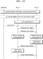
- FIG. 7 is a diagram for describing a method of transmitting and receiving a path loss measurement signal to estimate a sidelink path loss, according to another disclosed embodiment.
- FIG. 7 may correspond to a detailed embodiment of (b) of FIG. 4 .
- V2X UEs in coverage of a base station may perform downlink synchronization and may obtain system information.
- the downlink synchronization may be performed through a primary synchronization signal/secondary synchronization signal (PSS/SSS) received from the base station, or may be performed through a synchronization signal received from a global navigation satellite system (GNSS).
- PSS/SSS primary synchronization signal/secondary synchronization signal
- GNSS global navigation satellite system
- the V2X UEs performing the downlink synchronization may obtain system information related to V2X through a V2X dedicated system information block (SIB) transmitted by the base station gNB /RSU.
- SIB V2X dedicated system information block
- the V2X UEs in the coverage may perform uplink synchronization through a random access procedure with the base station and may perform an RRC connection procedure.
- the uplink synchronization and the RRC connection procedure may be performed by only one of a transmission UE or a reception UE, or may be performed by both the transmission UE and the reception UE.
- Information on which UE from among the transmission UE and the reception UE is to perform the uplink synchronization and the RRC connection procedure may vary according to a transmission mode of sidelink control information/data information, a sidelink path loss estimation procedure, a signaling method, etc.
- a transmission mode of sidelink control information/data information For example, as shown in FIG. 6 , in a mode in which the base station transmits a command for transmission of a path loss signal to a V2X reception UE, the reception UE may have to perform the uplink synchronization and the RRC connection procedure with the base station.
- the transmission UE may have to perform the uplink synchronization and the RRC connection procedure with the base station.
- both the reception UE and the transmission UE may have to perform the uplink synchronization and the RRC connection procedure with the base station according to a signaling method.
- a command of the base station is transmitted to the V2X transmission UE and the V2X reception UE through downlink control information (DCI), a MAC CE, or a UE dedicated RRC message
- DCI downlink control information
- MAC CE MAC CE
- UE dedicated RRC message the V2X transmission UE and the V2X reception UE may perform the uplink synchronization and the RRC connection procedure with the base station.
- the V2X transmission UE and the V2X reception UE may not perform the uplink synchronization and the RRC connection procedure with the base station.
- a reception UE may refer to a UE that receives sidelink control information and data information
- a transmission UE may refer to a UE that transmits sidelink control information and data information. Accordingly, the reception UE and the transmission UE in FIG. 7 may not be related to transmission and reception of a path loss signal.
- a V2X transmission UE or a V2X reception UE performing downlink synchronization or uplink synchronization and RRC connection configuration with the base station may perform sidelink configuration for unicast communication.
- Such unicast link configuration may be performed in a higher layer (e.g., an application layer), and as shown in FIG. 7 , the unicast link configuration may be performed between the V2X transmission UE that is to transmit V2X control information/data information in a unicast method and the V2X reception UE that is to receive the V2X control information/data information in the unicast method.
- the base station may engage in the unicast link configuration.
- the V2X transmission UE may transmit a request for the unicast link configuration to the base station, and the base station may transmit a response to the unicast link configuration to the V2X reception UE. Also, the base station may transmit a confirmation for the unicast link configuration to the V2X transmission UE and the V2X reception UE.
- the procedure may not be identified in a physical layer and a MAC layer.
- the base station may transmit a command for a transmission request of a signal for path loss estimation to the V2X transmission UE.
- the command of the base station may be transmitted to the V2X transmission UE through UE-specific DCI (or group common DCI) for a sidelink or through a MAC CE or a UE-specific RRC message.
- the DCI may use a radio network temporary identifier (RNTI) different from UE-specific DCI or group common DCI used in existing cellular communication for distinguishment from existing cellular communication.
- RNTI radio network temporary identifier
- a command transmitted by the base station to the V2X reception UE in FIG. 6 and a command transmitted by the base station to the V2X transmission UE in FIG. 7 may be transmitted through different UE-specific DCI (or group common DCI), MAC CEs, or UE-specific RRC.
- the different UE-specific DCI (or group common DCI) may be different DCI formats.
- the different MAC CEs may refer to different MAC CE formats.
- the V2X transmission UE receiving the command from the base station may transmit a request for transmission of a signal for path loss estimation to the V2X reception UE.
- the V2X reception UE receiving the request may transmit the signal for path loss estimation to the V2X transmission UE.
- the request for transmission of the signal for path loss estimation may be explicitly or implicitly performed.
- the V2X transmission UE may use a bit field for requesting to transmit the signal for path loss estimation in sidelink control information (SCI) transmitted via a sidelink control channel.
- SCI sidelink control information
- the implicit request may be performed when the V2X reception UE receives a specific signal from the V2X transmission UE.
- the V2X transmission UE may transmit a sidelink synchronization signal
- the V2X reception UE receiving the sidelink synchronization signal may transmit the signal for path loss estimation to the V2X transmission UE.
- the V2X transmission UE may transmit a request for transmission of the signal for path loss estimation to the V2X reception UE after unicast link configuration without the command of the base station.
- the V2X transmission UE may start a timer from a point of time when a request for unicast link configuration is received or from a point of time when the unicast link configuration succeeds, and may transmit the request of the signal for path loss estimation to the V2X reception UE at a point of time when the timer expires.
- the V2X reception UE may start a timer from a point of time when a request for unicast link configuration is transmitted or from a point of time when the unicast link configuration succeeds, and may expect to receive the request for transmission of the signal for path loss estimation from the V2X transmission UE at a point of time when the timer expires.
- the V2X transmission UE may transmit the request for transmission of the signal for path loss estimation to the V2X reception UE after a certain period of time (e.g., [x] subframes, [x] slots, or [x] ms) from a point of time when unicast link configuration succeeds.
- the V2X reception UE may expect to receive the request for transmission of the signal for path loss estimation after a certain period of time (e.g., [x] subframes, [x] slots, or [x] ms) from a point of time when unicast link configuration succeeds.
- a certain period of time e.g., [x] subframes, [x] slots, or [x] ms
- the V2X transmission UE transmits the request for transmission of the signal for path loss estimation to the V2X reception UE without the command of the base station
- an RSRP value measured by the V2X transmission UE with the base station is equal to or greater than (or greater than) a specific threshold value configured by the base station or is equal to or less than (or less than) a specific threshold value
- the V2X transmission UE may transmit the request for transmission of the signal for path loss estimation to the V2X reception UE.
- the base station may configure the RSRP threshold value in the V2X transmission UE through a system transmission block for V2X (V2X SIB) or a UE-specific RRC/common RRC message for V2X.
- the V2X transmission UE may transmit the request for transmission of the signal for path loss estimation to the V2X reception UE.
- the V2X transmission UE satisfies a condition for the RSRP threshold value configured by the base station, when the base station sends a command for stopping transmitting the request for transmission of the signal for path loss estimation, the V2X transmission UE may stop transmitting the request for transmission of the signal for path loss estimation.
- the V2X transmission UE transmits the request for transmission of the signal for path loss estimation to the V2X reception UE without the command of the base station
- a modulation order of V2X data information to be transmitted by the V2X transmission UE is equal to or greater than, or greater than a certain level
- the V2X transmission UE may transmit the request for transmission of the signal for path loss estimation to the V2X reception UE.
- the modulation order of the V2X data information to be transmitted by the V2X transmission UE is equal to or greater than 64-QAM (or is 256-QAM greater than 64-QAM)
- the V2X transmission UE may transmit the request for transmission of the signal for path loss estimation to the V2X reception UE.
- the V2X transmission UE may transmit the request for transmission of the signal for path loss estimation to the V2X reception UE.
- TBS transport block
- the V2X transmission UE may transmit the request for transmission of the signal for path loss estimation to the V2X reception UE.
- the V2X transmission UE may transmit the request for transmission of the signal for path loss estimation to the V2X reception UE (e.g., when the aggregation level is equal to or less than 8, or is equal to 4 that is less than 8).
- the V2X transmission UE transmits the signal for path loss estimation to the V2X reception UE without the command of the base station
- an RSRP value of a sidelink channel previously measured by the V2X transmission UE is equal to or greater than (or greater than) a specific threshold value configured by the base station, or is equal to or less than (or less than) a specific threshold value
- the V2X transmission UE may transmit the signal for path loss estimation to the V2X reception UE.
- the base station may configure the RSRP threshold value of the sidelink channel in the V2X transmission UE through a system transmission block for V2X (V2X SIB) or UE-specific RRC/common RRC message for V2X.
- the V2X transmission UE may transmit the signal for path loss estimation to the V2X reception UE.
- the V2X transmission UE may transmit the signal for path loss estimation to the V2X reception UE.
- X may be pre-defined, or may be configured by the base station.
- the V2X transmission UE may transmit the signal for path loss estimation to the V2X reception UE. Even when the V2X transmission UE satisfies a condition for the RSRP threshold value of the sidelink channel, which is configured by the base station, when the base station transmits a command for stopping transmitting the signal for path loss estimation, the V2X transmission UE may stop transmitting the signal for path loss estimation.
- a threshold value for the RSRP value of the sidelink channel or the variation of the RSRP value of the sidelink channel may be pre-configured without signaling from the base station.
- the V2X reception UE receiving the request for transmission of the signal for path loss estimation from the V2X transmission UE may transmit the signal for path loss estimation to the V2X transmission UE.
- the V2X transmission UE may receive information on transmission power of the signal for path loss estimation from the base station or the V2X reception UE.
- a method of transmitting the information on the transmission power of the signal for path loss estimation may be performed in various ways as described with reference to FIG. 6 .
- a method of configuring transmission power information of the signal for path loss estimation may be performed by using one of various examples described with reference to FIG. 6 .
- the V2X transmission UE receiving the signal for path loss estimation and the transmission power information of the signal for path loss estimation from the base station or the V2X reception UE may estimate a path loss value of a sidelink by using [Equation 1].
- the V2X transmission UE may configure a transmission power value of a physical channel (e.g., a sidelink control channel and a sidelink data channel) via which sidelink control information and data information are transmitted based on the estimated path loss value.
- the V2X transmission UE may transmit the sidelink control information and data information to the V2X reception UE based on the configured transmission power value.
- a groupcast communication method there may exist a group header functioning as a base station managing communication in a group. Because group headers function as base stations, V2X UEs may obtain a path loss value and may configure a transmission power value based on the path loss value.
- the V2X transmission UE may include timing information on timing when the signal for path loss estimation is to be transmitted by the V2X reception UE, in request information transmitted by the V2X transmission UE. That is, the V2X transmission UE may transmit timing-related information in a bit field of sidelink control information requesting the signal for path loss estimation, by using [z] bits.
- a unit representing the timing information may be the number of symbols (z symbols), the number of slots (z slots), or the number of subframes (z subframes). Accordingly, the V2X reception UE receiving the timing information may transmit the signal for path loss estimation after z symbols (or z slots or z subframes) from a point of time when the bit field is received.
- the timing information may be fixed, and the V2X transmission UE and the V2X reception UE may use a pre-agreed value.
- the base station may configure the timing information.
- the V2X transmission UE may transmit the timing information configured by the base station via a sidelink control channel, to a V2X reception UE existing out of coverage of the base station or to a V2X reception UE existing in a different base station.
- the V2X transmission UE may estimate a sidelink path loss value by using a signal for path loss estimation received from the V2X reception UE, and may configure a transmission power value of sidelink control information and data information based on the estimated sidelink path loss value.
- the V2X transmission UE may transmit a request for transmission of the signal for path loss estimation to the V2X reception UE, and the V2X reception UE may transmit a signal for sidelink path loss estimation to the V2X transmission UE based on the request.
- At least one of the following embodiments may be used.
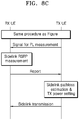
- FIG. 8A is a diagram for describing a method of transmitting and receiving a path loss measurement signal to estimate an inter-UE sidelink path loss, according to another disclosed embodiment.
- FIG. 8A may correspond to a detailed embodiment of (a) of FIG. 5 .
- V2X UEs in coverage of a base station may perform downlink synchronization and may obtain system information.
- the downlink synchronization may be performed through a primary synchronization signal/secondary synchronization signal (PSS/SSS) received from the base station, or may be performed through a synchronization signal received from a global navigation satellite system (GNSS).
- PSS/SSS primary synchronization signal/secondary synchronization signal
- GNSS global navigation satellite system
- the V2X UEs performing the downlink synchronization may obtain system information related to V2X through a V2X dedicated system information block (SIB) transmitted by the base station.
- SIB V2X dedicated system information block
- the V2X UEs in the coverage may perform uplink synchronization through a random access procedure with the base station and may perform an RRC connection procedure.
- the uplink synchronization and the RRC connection procedure may be performed by only one of a transmission UE or a reception UE, or may be performed by both the transmission UE and the reception UE.
- Information on which UE from among the transmission UE and the reception UE is to perform the uplink synchronization and the RRC connection procedure may vary according to a transmission mode of sidelink control information/data information, a sidelink path loss estimation procedure, and a signaling method. For example, as shown in FIG.
- a mode in which the base station transmits a command for transmission of a path loss signal to a V2X transmission UE the transmission UE may have to perform the uplink synchronization and the RRC connection procedure with the base station. Also, as shown in FIG. 9 , in a mode in which the base station transmits a command for transmission of a path loss signal to a V2X reception UE, the reception UE may have to perform the uplink synchronization and the RRC connection procedure with the base station.
- both the reception UE and the transmission UE may have to perform the uplink synchronization and the RRC connection procedure with the base station according to a signaling method. For example, when a command of the base station is transmitted to the V2X transmission UE and the V2X reception UE through DCI, a MAC CE, or UE dedicated RRC, the V2X transmission UE and the V2X reception UE may perform the uplink synchronization and the RRC connection procedure with the base station.
- the V2X transmission UE and the V2X reception UE may not perform the uplink synchronization and the RRC connection procedure with the base station.
- the V2X transmission UE or reception UE performing the uplink synchronization and the RRC connection configuration with the base station may perform unicast link configuration.
- the unicast link configuration may be performed in a higher layer (e.g., an application layer), and as shown in FIG. 8A , the unicast link configuration may be performed between the V2X transmission UE that is to transmit V2X control information/data information in a unicast method and the V2X reception UE that is to receive the V2X control information/data information in the unicast method.
- the base station may engage in the unicast link configuration.
- the V2X transmission UE may transmit a request for the unicast link configuration to the base station, and the base station may transmit a response to the request to the V2X reception UE. Also, the base station may transmit a confirmation for the unicast link configuration to the V2X transmission UE and the V2X reception UE.
- the procedure may not be identified in a physical layer and a MAC layer.
- the base station may transmit a command for transmission of a signal for path loss estimation to the V2X transmission UE.
- the command of the base station may be transmitted to the V2X transmission UE through UE-specific DCI (or group common DCI) for a sidelink or through a MAC CE or UE-specific RRC.
- the DCI may use a radio network temporary identifier (RNTI) different from UE-specific DCI or group common DCI used in existing cellular communication for distinguishment from existing cellular communication.
- RNTI radio network temporary identifier
- the V2X transmission UE may transmit the signal for path loss estimation after unicast link configuration without the command of the base station.
- the V2X transmission UE may start a timer from a point of time when a request for unicast link configuration is received or from a point of time when the unicast link configuration succeeds, and may transmit the signal for path loss estimation at a point of time when the timer expires.
- the V2X reception UE may start a timer from a point of time when a request for unicast link configuration is transmitted or from a point of time when the unicast link configuration succeeds, and may expect to receive the signal for path loss estimation from the V2X transmission UE at a point of time when the timer expires.
- the V2X transmission UE may transmit the signal for path loss estimation after a certain period of time (e.g., after [x] subframes, [x] slots, or [x] ms) from a point of time when unicast link configuration succeeds.
- the V2X reception UE may receive the signal for path loss estimation from the V2X transmission UE after a certain period of time (e.g., [x] subframes, [x] slots, or [x] ms) from a point of time when unicast link configuration succeeds.
- a certain period of time e.g., [x] subframes, [x] slots, or [x] ms
- the V2X transmission UE transmits the signal for path loss estimation without the command of the base station
- an RSRP value measured by the V2X transmission UE with the base station is equal to or greater than (or greater than) a specific threshold value configured by the base station or is equal to or less than (or less than) a specific threshold value
- the V2X transmission UE may transmit the signal for path loss estimation to the V2X reception UE.
- the base station may configure the RSRP value in the V2X transmission UE through a system transmission block for V2X SIB (V2XSIB), or a UE-specific RRC/common RRC message for V2X.
- V2XSIB system transmission block for V2X SIB
- UE-specific RRC/common RRC message for V2X.
- the V2X transmission UE may transmit the signal for path loss estimation to the V2X reception UE.
- the V2X transmission UE satisfies a condition for the RSRP value configured by the base station, when the base station sends a command for stopping transmitting the signal for path loss estimation, the V2X transmission UE may stop transmitting the signal for path loss estimation.
- the V2X transmission UE transmits the signal for path loss estimation without the command of the base station
- a modulation order of V2X data information to be transmitted by the V2X transmission UE is equal to or greater than, or greater than a certain level
- the V2X transmission UE may transmit the signal for path loss estimation.
- the modulation order of the V2X data information to be transmitted by the V2X transmission UE is equal to or greater than 64-QAM (or is 256-QAM greater than 64-QAM)
- the V2X transmission UE may transmit the signal for path loss estimation to the V2X reception UE.
- the V2X transmission UE may transmit the signal for path loss estimation (e.g., when the aggregation level is equal to or less than 8, or is equal to 4 that is less than 8).
- the V2X transmission UE may transmit the signal for path loss estimation to the V2X reception UE.
- the V2X transmission UE may always transmit the signal for path loss estimation to the V2X reception UE along with the sidelink control information and data information.
- the V2X transmission UE transmits the signal for path loss estimation to the V2X reception UE without the command of the base station
- an RSRP value of a sidelink channel previously measured by the V2X transmission UE is equal to or greater than (or greater than) a specific threshold value configured by the base station, or is equal to or less than (or less than) a specific threshold value
- the V2X transmission UE may transmit the signal for path loss estimation to the V2X reception UE.
- the base station may configure the RSRP threshold value of the sidelink channel in the V2X transmission UE through a system transmission block for V2X (V2X SIB), or a UE-specific RRC/common RRC message for V2X.
- the V2X transmission UE may transmit the signal for path loss estimation to the V2X reception UE.
- the V2X transmission UE may transmit the signal for path loss estimation to the V2X reception UE.
- X may be pre-defined or may be configured by the base station.
- the V2X transmission UE may transmit the signal for path loss estimation to the V2X reception UE. Even when the V2X transmission UE satisfies a condition for the sidelink RSRP threshold value of the sidelink channel, which is configured by the base station, when the base station transmits a command for stopping transmitting the signal for path loss estimation, the V2X transmission UE may stop transmitting the signal for path loss estimation.
- a threshold value of the RSRP value of the sidelink channel or the variation of the RSRP value of the sidelink channel may be pre-configured without signaling from the base station.
- V2X transmission UEs may refer to UEs having a capability to transmit a signal for V2X path loss estimation. Accordingly, from among UEs having the capability, V2X transmission UEs satisfying the above conditions may transmit the signal for path loss estimation.
- the base station may transmit a command for transmission of the signal for path loss estimation to the V2X transmission UE, and whether the V2X transmission UE is capable of transmitting the signal for path loss estimation may be a V2X UE capability (i.e., only UEs having a capability to transmit a signal for V2X path loss estimation may transmit the signal for V2X path loss estimation).
- the command of the base station may be transmitted to the V2X transmission UE having the capability through UE-specific DCI (or group common DCI) for a sidelink or through a UE-specific RRC message.
- the V2X transmission UE receiving the command for transmission of the signal for path loss estimation may transmit the signal for path loss estimation to the V2X reception UE.
- the V2X transmission UE that is to transmit the signal for path loss estimation may transmit the signal for path loss estimation to the V2X reception UE.
- the V2X reception UE may obtain information on transmission power of the signal for path loss estimation by using one of the following various methods.
- a method of transmitting the information on the transmission power of the signal for path loss estimation according to an embodiment will be described below.
- the V2X transmission UE may transmit the information on the transmission power of the signal for path loss estimation to the V2X reception UE through at least one of the above embodiments.
- the V2X transmission UE may configure transmission power information of the signal for path loss estimation by using at least one of the following embodiments.
- the base station or the V2X transmission UE may transmit a signal for path loss estimation and transmission power information of the signal for path loss estimation to the V2X reception UE.
- the V2X reception UE receiving the same may estimate a path loss value of a sidelink by using [Equation 1].
- the V2X reception UE may report an estimation result to the V2X transmission UE.
- a reporting method may be performed through one of the following various methods.
- the V2X reception UE may report a path loss estimation result to the V2X transmission UE, and in this case, the V2X reception UE may report RSRP measured by the V2X reception UE itself or may directly report a path loss value estimated by the V2X reception UE itself.
- the V2X reception UE may report RSRP measured by the V2X reception UE itself or may report a path loss value measured by the V2X reception UE itself to the V2X transmission UE.
- a reported RSRP value or a path loss value may be transmitted via the following channels.
- a channel via which reported information is transmitted according to an embodiment will be described below.
- V2X reception UE When a specific V2X reception UE reports an RSRP value or a path loss value by using the above channels, other V2X reception UEs may also be performing reporting. Accordingly, in order to prevent collision and interference between resources used by different V2X reception UEs, it may be necessary to allocate and control a resource in which reported information is transmitted. To this end, there may be the following methods.
- the V2X reception UE may periodically or aperiodically report the result.
- periodic or aperiodic reporting may have a relationship with an interval in which the V2X reception UE is to perform reporting.
- a reception UE may continuously perform reporting during a reporting interval, that is, between a start time and an end time of reporting.
- the reception UE may perform reporting once at a reporting time rather than configuring an interval during which reporting is performed.
- the V2X reception UE needs to determine a reporting timing regarding when to perform reporting.
- a reporting time according to an embodiment will be described below.
- the V2X reception UE When the V2X reception UE receives a signal for path loss estimation from the V2X transmission UE and then reports a result to the V2X transmission UE, the V2X reception UE needs to determine how to configure a transmission power value of a channel for reporting.
- the V2X transmission UE may transmit sidelink control information and data information to the V2X reception UE based on an RSRP value or a path loss estimation value reported from the V2X reception UE.
- a groupcast communication method there may exist a group header functioning as a base station managing communication in a group.
- Such group headers may function as base stations.
- FIG. 8B is a diagram for describing in more detail a method of estimating an inter-UE sidelink path loss according to an embodiment of FIG. 8A .
- a transmission UE may transmit a signal for path loss estimation to a reception UE, the reception UE receiving the signal may measure RSRP by using a path loss estimation signal and may report the RSRP to the transmission UE, and the transmission UE may estimate a path loss value of a sidelink by using the received RSRP.
- the RSRP reported by the reception UE to the transmission UE may be L1-RSRP or L3-RSRP.
- FIG. 8B illustrates a specific example where the reception UE reports L1-RSRP to the transmission UE.
- FIG. 8B the same procedure as that in FIG. 8A will not be described.
- downlink synchronization with a base station and system parameter acquisition, uplink synchronization and RRC connection configuration, and unicast link configuration (PC-5 RRC connection configuration) between the transmission UE and the reception UE may be performed in the same manner as that in FIG. 8A .
- the transmission UE may receive a command for transmission of a sidelink path loss estimation signal from the base station.
- an L3-RSRP value filtered in layer 3 is required.
- a physical layer may calculate an L1-RSRP value and may transmit the L1-RSRP value to layer 3, and the layer 3 may obtain the L3-RSRP value by obtaining an average in a time domain, or a time domain and a spatial domain by using the L1-RSRP value received from the physical layer.
- an average needs to be obtained during a sufficiently long time.
- the reception UE When the reception UE reports L1-RSRP to the transmission UE, the above L3 filtering operation has to be performed during a sufficiently long time for accurate path loss estimation. To this end, the reception UE may have to report the L1-RSRP to the transmission UE several times. Because the L1-RSRP is a value calculated in the layer 1, the L1-RSRP may be transmitted via a sidelink feedback channel (physical sidelink feedback channel (PSFCH)) or a sidelink data channel (physical sidelink shared channel (PSSCH)). Accordingly, when the reception UE has to report the L1-RSRP to the transmission UE several times, it means that the reception UE has to transmit the PSFCH or the PSSCH to the transmission UE several times.
- a sidelink feedback channel physical sidelink feedback channel (PSFCH)
- PSSCH sidelink shared channel
- the reception UE may not be able to simultaneously perform transmission and reception, the reception UE may not be able to receive sidelink control information and data information that may be transmitted from another transmission UE while the reception UE transmits the PSFCH or the PSSCH several times. Also, the V2X UE may not be able to simultaneously transmit two or more different channels in one carrier (i.e., two or more different channels may not be frequency-divided and transmitted in one carrier). Accordingly, while the reception UE transmits the PSFCH or the PSSCH to the transmission UE several times to report the L1-RSRP, the reception UE may not be able to transmit sidelink control information and data information to another UE. In order to solve these problems, N L1-RSRP reports may be transmitted in the time domain once through a MAC CE shown in (c) or (d) of FIG. 8D .
- agreement related to transmission and reception of the L1-RSRP may be required between the transmission UE and the reception UE so that the transmission UE receives the L1-RSRP transmitted by the reception UE and performs L3 filtering.
- agreement as to when to report the L1-RSRP to the transmission UE may be required.
- the transmission UE needs to know a point of time when an L1-RSRP report is transmitted from the reception UE after the sidelink path loss estimation signal is transmitted.
- the transmission UE may expect that the L1-RSRP is to be reported from the reception UE after [x1] ms or [x2] slots, from a slot on which the sidelink path loss estimation signal is transmitted.
- the reception UE may not be able to report the L1-RSRP to the transmission UE. Accordingly, in order for the transmission UE to perform L3 filtering by using the L1-RSRP reported from the reception UE, a sufficiently long reception window time needs to be secured.
- the transmission UE may attempt to receive the L1-RSRP during + ⁇ 1 ms or - ⁇ 1 ms from [x1] ms, or may attempt to receive the L1-RSRP during + ⁇ 2 ms or - ⁇ 2 ms from [x2] slots.
- the transmission UE may have to perform filtering during a total of [x4] ms or a total of [x3] L1-RSRP values reported from the reception UE every [x1] ms or every [x2] slots. Accordingly, the reception UE may have to continuously perform transmission to the transmission UE, until the number of L1-RSRP values reported every [x1] ms or [x2] slots is a total of [x3] (the total number of L1-RSRP values reported by the reception UE to the transmission UE is N in FIG. 8B ). Alternatively, the reception UE may have to continuously transmit, to the transmission UE, the L1-RSRP reported every [x1] ms or [x2] slots up to a total of [x4] ms.
- the transmission UE may transmit a command for stopping reporting the L1-RSRP to the reception UE.
- the reception UE may report the L1-RSRP every [x1] ms or [x2] slots, until the reception UE receives the command for stopping reporting the L1-RSRP from the transmission UE.
- the command for stopping reporting the L1-RSRP may be included in PC-5 RRC signaling, a MAC CE, or SCI information.
- an operation may be performed based on a timer.
- the transmission UE may transmit a sidelink path loss estimation signal and may start a T1 timer.
- the transmission UE may maintain a reception window for receiving an L1-RSRP value reported from the reception UE until the T1 timer expires.
- the transmission UE may derive a layer-3 RSRP value by using an L1-RSRP report received until the T1 timer expires.
- the reception UE may receive the sidelink path loss estimation signal and may start a T2 timer.
- the reception UE may transmit an L1-RSRP value to the transmission UE at least once on an available resource until the T2 timer expires.
- the reception UE may stop transmitting the L1-RSRP report.
- T1 and T2 may be the same or different from each other.
- the transmission UE may transmit information for notifying this (e.g., HARQ-NACK) to the reception UE.
- the reception UE receiving the information may re-configure the T2 timer that is previously running (i.e., reset the T2 timer that is previously running) and may report the L1-RSRP to the transmission UE.
- the transmission UE when the transmission UE secures sufficient L1-RSRP samples for performing layer-3 filtering before the T1 timer expires (i.e., when N RSRP values are secured), the transmission UE may transmit information for notifying this (e.g., transmission of HARQ-ACK) to the reception UE and may terminate the T1 timer.
- the reception UE receives the information indicating that sufficient L1-RSRP samples are secured from the transmission UE and the T2 timer of the reception UE does not expire, the reception UE may terminate the T2 timer.
- [x1], [x2], [x3], [x4], ⁇ 1, ⁇ 2, T1, T2 and filtering coefficients for performing L3 filtering may be configured by the base station through system information or RRC signaling.
- the transmission UE and the reception UE may perform PC-5 RRC connection configuration during unicast link connection configuration, and in this case, through PC-5 RRC signaling.
- the parameters may be fixed values, which may refer to values embedded in the transmission UE and the reception UE.
- FIG. 8C is another diagram for describing in more detail a method of estimating an inter-UE sidelink path loss according to an embodiment of FIG. 8A .
- FIG. 8C the same procedure as that in FIG. 8A will not be described.
- downlink synchronization with a base station and system parameter acquisition, uplink synchronization and RRC connection configuration, and unicast link configuration (PC-5 RRC connection configuration) between a transmission UE and a reception UE may be performed in the same manner as that in FIG. 8A .
- the transmission UE may receive a command for transmission of a sidelink path loss estimation signal from the base station.
- the reception UE when the reception UE reports L1-RSRP to the transmission UE, the reception UE may report RSRP to the transmission UE only once. Accordingly, problems occurring when the reception UE reports L1-RSRP to the transmission UE may be solved. However, in the case of L3-RSRP reporting, because a final value of reported RSRP is generated in layer 3, L3-RSRP has to be reported from RRC of the reception UE and transmitted to RRC of the transmission UE, and may be transmitted via a PSSCH.
- Agreement may be required between the transmission UE and the reception UE so that the transmission UE receives the L3-RSRP transmitted by the reception UE and estimates a sidelink path loss value.
- agreement as to when to report the L3-RSRP to the transmission UE may be required.
- the transmission UE needs to know a point of time when an L3-RSRP report is transmitted from the reception UE after the sidelink path loss estimation signal is transmitted.
- the transmission UE may expect that the L3-RSRP is to be reported from the reception UE after [x1] ms or [x2] slots, from a slot on which the sidelink path loss estimation signal is transmitted.
- the reception UE may not be able to report the L3-RSRP to the transmission UE. Accordingly, in order for the transmission UE to estimate a sidelink path loss value by using the L3-RSRP reported from the reception UE, a sufficiently long reception window time needs to be secured.
- the transmission UE may attempt to receive the L3-RSRP during + ⁇ 1 ms or - ⁇ 1 ms from [x1] ms, or may attempt to receive the L3-RSRP during + ⁇ 2 ms or - ⁇ 2 ms from [x2] slots.
- an operation may be performed based on a timer.
- the transmission UE may transmit a sidelink path loss estimation signal and may start a T1 timer.
- the transmission UE may main a reception window for receiving an L3-RSRP value reported from the reception UE until the T1 timer expires.
- the reception UE may receive the sidelink path loss estimation signal and may start a T2 timer.
- the reception UE may perform an operation for finding an available resource for reporting the L3-RSRP value to the transmission UE (e.g., a sensing and resource selection operation) until the T2 timer expires.
- the reception UE not finding the available resource for reporting the L3-RSRP until the T2 timer expires may stop reporting the L3-RSRP.
- T1 and T2 may be the same or different from each other.
- the transmission UE may give up receiving the L3-RSRP.
- the transmission UE may transmit information indicating this (e.g., HARQ-NACK) to the reception UE.
- the reception UE receiving the information may re-configure the T2 timer that is previously running (i.e., reset the T2 timer that is previously running), and may re-report the L3-RSRP to the transmission UE.
- [x1], [x2] through ⁇ 1, ⁇ 2, T1, T2 and filtering coefficients for performing L3 filtering may be configured by the base station through system information or RRC signaling.
- the transmission UE and the reception UE may perform PC-5 RRC connection configuration during unicast link connection configuration, and in this case, through PC-5 RRC signaling.
- the parameters may be fixed values, which may refer to values embedded in the transmission UE and the reception UE.
- FIG. 8D is a diagram for describing a MAC CE format for reporting an inter-UE sidelink RSRP value.
- the reception UE may be configured with information on whether to report L1-RSRP by using the MAC CE of (a) of FIG. 8D or to report L1-RSRP by using the MAC CE of (c) and/or (d) of FIG. 8D . It means that the transmission UE may be configured with information on whether to receive L1-RSRP by using the MAC CE of (a) of FIG. 8D or to receive L1-RSRP by using the MAC CE of (c) and/or (d) of FIG. 8D .
- This configuration may be received through system information or RRC signaling of a base station or may be received through PC-5 RRC signaling. In another example, this configuration may be pre-configured.
- FIG. 9 is a diagram for describing a method of transmitting and receiving a path loss measurement signal to estimate an inter-UE sidelink path loss, according to another disclosed embodiment.
- FIG. 9 may correspond to a detailed embodiment of (b) of FIG. 5 .
- V2X UEs in coverage of a base station may perform downlink synchronization and may obtain system information.
- the downlink synchronization may be performed through a primary synchronization signal/secondary synchronization signal (PSS/SSS) received from the base station, or may be performed through a synchronization signal received from a global navigation satellite system (GNSS).
- PSS/SSS primary synchronization signal/secondary synchronization signal
- GNSS global navigation satellite system
- the V2X UEs performing the downlink synchronization may obtain system information related to V2X through a V2X dedicated system information block (SIB) transmitted by the base station gNB /RSU.
- SIB V2X dedicated system information block
- the V2X UEs in the coverage may perform uplink synchronization through a random access procedure with the base station and may perform an RRC connection procedure.
- the uplink synchronization and the RRC connection procedure may be performed by only one of a transmission UE or a reception UE, or may be performed by both the transmission UE and the reception UE.
- Information on which UE from among the transmission UE and the reception UE is to perform the uplink synchronization and the RRC connection procedure may vary according to a transmission mode of sidelink control information/data information, a sidelink path loss estimation procedure, a signaling method, etc.
- a transmission mode of sidelink control information/data information For example, as shown in FIG. 8A , in a mode in which the base station transmits a command for transmission of a path loss signal to a V2X transmission UE, the transmission UE may have to perform the uplink synchronization and the RRC connection procedure with the base station.
- the reception UE may have to perform the uplink synchronization and the RRC connection procedure with the base station.
- both the reception UE and the transmission UE may perform the uplink synchronization and the RRC connection procedure with the base station according to a signaling method.
- a reception UE may refer to a UE that receives sidelink control information and data information
- a transmission UE may refer to a UE that transmits sidelink control information and data information. Accordingly, the reception UE and the transmission UE in FIG. 9 may not be related to transmission and reception of a path loss signal.
- a V2X transmission UE or a V2X reception UE performing uplink synchronization and RRC connection configuration with the base station may perform unicast link configuration.
- This unicast link configuration may be performed in a higher layer (e.g., an application layer), and as shown in FIG. 9 , the unicast link configuration may be performed between the V2X transmission UE that is to transmit V2X control information/data information in a unicast method and the V2X reception UE that is to receive the V2X control information/data information in the unicast method.
- the base station may engage in the unicast link configuration.
- the V2X transmission UE may transmit a request for the unicast link configuration to the base station, and the base station may transmit a response to the unicast link configuration to the V2X reception UE. Also, the base station may transmit a confirmation for the unicast link configuration to the V2X transmission UE and the V2X reception UE.
- the procedure may not be identified in a physical layer and a MAC layer.
- the base station may transmit a command for a transmission request of a signal for path loss estimation to the V2X reception UE.
- the command of the base station may be transmitted to the V2X reception UE through UE-specific DCI (group common DCI) for a sidelink or through a MAC CE or a UE-specific RRC message.
- the DCI may use a radio network temporary identifier (RNTI) different from UE-specific DCI or group common DCI used in existing cellular communication for distinguishment from existing cellular communication.
- RNTI radio network temporary identifier
- the V2X reception UE may transmit a request for transmission of the signal for path loss estimation to the V2X transmission UE after unicast link configuration without the command of the base station.
- the V2X reception UE may start a timer from a point of time when a request for unicast link configuration is received or from a point of time when the unicast link configuration succeeds, and may transmit the request for transmission of the signal for path loss estimation at a point of time when the timer expires.
- the V2X transmission UE may start a timer from a point of time when a request for unicast link configuration is transmitted or from a point of time when the unicast link configuration succeeds, and may expect to receive the request for transmission of the signal for path loss estimation from the V2X reception UE at a point of time when the timer expires.
- the V2X reception UE may transmit the request for transmission of the signal for path loss estimation to the V2X transmission UE after a certain period of time (e.g., after [x] subframes, [x] slots, or [x] ms) from a point of time when unicast link configuration succeeds.
- the V2X transmission UE may expect to receive the request for transmission of the signal for path loss estimation from the V2X reception UE after a certain period of time (e.g., [x] subframes, [x] slots, or [x] ms) from a point of time when unicast link configuration succeeds.
- a certain period of time e.g., [x] subframes, [x] slots, or [x] ms
- the V2X reception UE transmits the request of the signal for path loss estimation to the V2X transmission UE without the command of the base station
- an RSRP value measured by the V2X reception UE with the base station is equal to or greater than (or greater than) a specific threshold value configured by the base station or is equal to or less than (or less than) a specific threshold value
- the V2X reception UE may transmit the request of the signal for path loss estimation to the V2X transmission UE.
- the base station may configure the RSRP threshold value in the V2X reception UE through a system transmission block for V2X (V2X SIB) or a UE-specific RRC/common RRC message for V2X.
- the V2X reception UE may transmit the request for transmission of the signal for path loss estimation to the V2X transmission UE.
- the V2X reception UE satisfies a condition for the RSRP value configured by the base station, when the base station sends a command for stopping transmitting the request for transmission of the signal for path loss estimation, the V2X reception UE may stop transmitting the request for transmission of the signal for path loss estimation.
- the V2X reception UE transmits the request of the signal for path loss estimation to the V2X transmission UE without the command of the base station
- an RSRP value of a sidelink channel measured by the V2X reception UE is equal to or greater than (or greater than) a specific threshold value configured by the base station or is equal to or less than (or less than) a specific threshold value
- the V2X reception UE may transmit the request for transmission of the signal for path loss estimation to the V2X transmission UE.
- the base station may configure the RSRP value of the sidelink channel in the V2X reception UE through a system transmission block for V2X (V2X SIB) or a UE-specific RRC/common RRC message for V2X.
- the V2X reception UE may transmit the request for transmission of the signal for path loss estimation to the V2X transmission UE.
- the V2X reception UE may transmit the request of the signal for path loss estimation to the V2X transmission UE.
- X may be pre-defined, or may be configured by the base station.
- the V2X reception UE may transmit the request for transmission of the signal for path loss estimation to the V2X transmission UE. Even when the V2X reception UE satisfies a condition for the RSRP value of the sidelink channel, which is configured by the base station, when the base station transmits a command for stopping transmitting the request for transmission of the signal for path loss estimation, the V2X reception UE may stop transmitting the request for transmission of the signal for path loss estimation.
- a threshold value for the RSRP value of the sidelink channel or the variation of the RSRP value of the sidelink channel may be pre-configured without signaling from the base station.
- V2X transmission UEs may refer to UEs having a capability to transmit a signal for V2X path loss estimation. Accordingly, it may be assumed that the V2X reception UE may previously know information on the V2X transmission UEs having the capability to transmit the signal for path loss estimation.
- the base station may transmit a command for transmission of the request of the signal for path loss estimation to the V2X reception UE, and whether the V2X transmission UE is capable of transmitting the signal for path loss estimation may be a V2X UE capability (i.e., only UEs having a capability to transmit a signal for V2X path loss estimation may transmit the signal for V2X path loss estimation). Accordingly, the base station may transmit the command to the V2X reception UE by considering the capability of the V2X transmission UE. In this case, the command of the base station may be transmitted to the V2X reception UE through UE-specific DCI (or group common DCI) for a sidelink or through UE-specific RRC.
- UE-specific DCI or group common DCI
- the V2X reception UE receiving the command for transmission of the request of the signal for path loss estimation may transmit the request for transmission of the signal for path loss estimation to the V2X transmission UE.
- the V2X reception UE that is to transmit the request for transmission of the signal for path loss estimation may transmit the request for transmission of the signal for path loss estimation to the V2X transmission UE.
- the V2X transmission UE receiving the request may transmit the signal for path loss estimation to the V2X reception UE.
- the V2X reception UE may obtain information on transmission power of the signal for path loss estimation from the V2X transmission UE by using various methods.
- a method of transmitting the information on the transmission power of the signal for path loss estimation may be performed in various ways as described with reference to FIG. 8A . Also, a method of configuring transmission power information of the signal for path loss estimation may be performed by using one of various examples described with reference to FIG. 8A .
- the V2X reception UE receiving the signal for path loss estimation and the transmission power information of the signal for path loss estimation from the base station or the V2X transmission UE may estimate a path loss value of a sidelink by using [Equation 1], and may report the estimated path loss value to the V2X transmission UE.
- [Equation 1] the path loss value of a sidelink
- the V2X reception UE may report an RSRP value measured by the V2X reception UE itself, instead of reporting a path loss value.
- a reporting method a channel in which reported information is transmitted, a resource in which reported information is transmitted, a point of time when reported information is transmitted, and a method of configuring an initial transmission power value of a channel in which reported information is transmitted, there may be various methods as described with reference to FIG. 8A .
- the V2X reception UE may estimate a sidelink path loss value by using a signal for path loss estimation received from the V2X transmission UE, and may configure a transmission power value of sidelink control information and data information based on the estimated sidelink path loss value. In this case, it may be necessary to determine how to configure a transmission power value of the signal for path loss estimation transmitted to the V2X reception UE.
- the V2X reception UE may transmit a request for transmission of the signal for path loss estimation to the V2X transmission UE, and the V2X transmission UE may transmit a signal for sidelink path loss estimation to the V2X reception UE based on the request.
- it may be necessary to determine how to configure transmission power values of the request for transmission of the signal for path loss estimation transmitted by the V2X reception UE to the V2X transmission UE and the signal for sidelink path loss estimation transmitted by the V2X transmission UE to the V2X reception UE.
- at least one of the following methods may be used.
- FIG. 10 is a diagram illustrating a method of transmitting and receiving a path loss measurement signal to estimate an inter-UE sidelink path loss, according to another embodiment of the present disclosure.
- FIG. 10 is a diagram illustrating a method of estimating a path loss in both directions.
- estimation in both directions may refer to a case where a V2X reception UE estimates a path loss value by receiving a signal for path loss estimation transmitted by a V2X transmission UE and the V2X transmission UE estimates a path loss value by receiving a signal for path loss estimation transmitted by the V2X reception UE.
- V2X UEs in coverage of a base station may perform downlink synchronization and may obtain system information.
- the downlink synchronization may be performed through a primary synchronization signal/secondary synchronization signal (PSS/SSS) received from the base station, or may be performed through a synchronization signal received from a global navigation satellite system (GNSS).
- the V2X UEs performing the downlink synchronization may obtain system information related to V2X through a V2X dedicated system information block (SIB) transmitted by the base station gNB/RSU.
- the V2X UEs in the coverage may perform uplink synchronization through a random access procedure with a base station and may perform an RRC connection procedure.
- the uplink synchronization and the RRC connection procedure may be performed by only one of a transmission UE or a reception UE, or may be performed by both the transmission UE and the reception UE.
- Information on which UE from among the transmission UE and the reception UE is to perform the uplink synchronization and the RRC connection procedure may vary according to a transmission mode of sidelink control information/data information, a sidelink path loss estimation procedure, a signaling method, etc.
- a mode in which the base station transmits a command for transmission of a path loss signal to a V2X transmission UE the transmission UE may have to perform the uplink synchronization and the RRC connection procedure with the base station.
- the reception UE in a mode in which the base station transmits a command for transmission of a path loss signal to a V2X reception UE, the reception UE may have to perform the uplink synchronization and the RRC connection procedure with the base station.
- both the reception UE and the transmission UE may perform the uplink synchronization and the RRC connection procedure with the base station according to a signaling method by which the base station transmits a command for transmission of a path loss signal
- a signaling method by which the base station transmits a command for transmission of a path loss signal
- the reception UE and the transmission UE may perform the uplink synchronization and the RRC connection procedure with the base station.
- the command for transmission of the path loss signal is transmitted through a V2X dedicated SIB, the reception UE and the transmission UE may not perform the uplink synchronization and the RRC connection procedure with the base station.
- a reception UE may refer to a UE that receives sidelink control information and data information
- a transmission UE may refer to a UE that transmits sidelink control information and data information. Accordingly, the reception UE and the transmission UE in FIG. 10 may not be related to transmission and reception of a path loss signal.
- a V2X transmission UE or a V2X reception UE may perform unicast link configuration.
- the unicast link configuration may be performed in a higher layer (e.g., an application layer), and as shown in FIG. 10 , the unicast link configuration may be performed between the V2X transmission UE that is to transmit V2X control information/data information in a unicast method and the V2X reception UE that is to receive the V2X control information/data information in the unicast method.
- the base station may engage in the unicast link configuration.
- the V2X transmission UE may transmit a request for the unicast link configuration to the base station, and the base station may transmit a response to the unicast link configuration to the V2X reception UE. Also, the base station may transmit a confirmation for the unicast link configuration to the V2X transmission UE and the V2X reception UE.
- the procedure may not be identified in a physical layer and a MAC layer.
- the base station may transmit a command for transmission of a signal for path loss estimation to the V2X transmission UE and the V2X reception UE.
- the command of the base station may be transmitted to the V2X transmission UE through UE-specific DCI (group common DCI) for a sidelink or through a MAC CE or UE-specific RRC.
- the DCI may use a radio network temporary identifier (RNTI) different from UE-specific DCI or group common DCI used in existing cellular communication for distinguishment from existing cellular communication.
- RNTI radio network temporary identifier
- RRC parameters may include at least one of a time resource, a frequency resource, and a code resource in which the signal for path loss estimation is transmitted.
- the time resource may include at least one information from among a start point at which the signal for path loss estimation is transmitted (at least one of a symbol index, a slot index, or a subframe index) and a transmission period.
- the frequency resource may include at least one information from among a start point of a resource block (RB) at which the signal for path loss estimation is transmitted, a size of the RB, a resource pool, and a bandwidth index (when a partial bandwidth is used).
- the code resource may include at least one information from among a sequence index used for the signal for path loss estimation, a scrambling ID, and a cyclic shift.
- information on a transmission resource of the signal for path loss estimation may be configured in the V2X transmission UE and the V2X reception UE through UE-specific RRC or common RRC signaling, and a transmission time of the signal for path loss estimation is activated through a MAC CE, UE-specific DCI, or group common DCI.
- the V2X transmission UE receiving the signal may transmit the signal for path loss estimation to the V2X reception UE in response.
- Information on when the V2X reception UE is to transmit the signal for path loss estimation may be determined by using one of various embodiments described with reference to FIG. 6 .
- the V2X reception UE receiving the request may transmit the signal for path loss estimation to the V2X transmission UE and the V2X transmission UE may transmit the signal for path loss estimation to the V2X reception UE in response.
- Information on when the V2X transmission UE is to transmit the request of the signal for path loss estimation to the V2X reception UE may be determined by using one of various embodiments described with reference to FIG. 7 .
- the V2X reception UE receiving the signal may transmit the signal for path loss estimation to the V2X transmission UE in response.
- Information on when the V2X transmission UE is to transmit the signal for path loss estimation may be determined by using one of various methods described with reference to FIG. 8A .
- the base station transmits a command for transmission of a request for transmission of the signal for path loss estimation to the V2X reception UE and the V2X reception UE transmits the request for transmission of the signal for path loss estimation to the V2X transmission UE
- the V2X transmission UE receiving the request may transmit the signal for path loss estimation to the V2X reception UE and the V2X reception UE may transmit the signal for path loss estimation to the V2X transmission UE in response.
- Information on when the V2X reception UE is to transmit the request of the signal for path loss estimation may be determined by using one of various embodiments described with reference to FIG. 9 .
- the V2X transmission UE and the V2X reception UE may transmit and receive the signal for path loss estimation after unicast link configuration, without the command of the base station.
- the V2X transmission UE may start a timer from a point of time when a request for unicast link configuration is received or from a point of time when the unicast link configuration succeeds, and may transmit the signal for path loss estimation at a point of time when the timer expires.
- the V2X reception UE may start a timer from a point of time when a request for unicast link configuration is transmitted or from a point of time when the unicast link configuration succeeds, and may transmit the signal for path loss estimation to the V2X transmission UE at a point of time when the timer expires.
- the V2X transmission UE may transmit the signal for path loss estimation after a certain period of time (e.g., after [x] subframes, [x] slots, or [x] ms) from a point of time when unicast link configuration succeeds.
- the V2X reception UE may transmit the signal for path loss estimation to the V2X transmission UE after a certain period of time (e.g., [x] subframes, [x] slots, or [x] ms) from a point of time when unicast link configuration succeeds.
- a certain period of time e.g., [x] subframes, [x] slots, or [x] ms
- pre-defined (pre-configured) parameters may be used and may include at least one of a time resource, a frequency resource, and a code resource in which the signal for path loss estimation is transmitted.
- the time resource may include at least one information from among a start point at which the signal for path loss estimation is transmitted (at least one of a symbol index, a slot index, or a subframe index) and a transmission period.
- the frequency resource may include at least one information from among a start point of a resource block (RB) at which the signal for path loss estimation is transmitted, a size of the RB, a resource pool, and a bandwidth index (when a partial bandwidth is used).
- the code resource may include at least one information from among a sequence index used for the signal for path loss estimation, a scrambling ID, and a cyclic shift.
- the V2X transmission UE and the V2X reception UE transmit the signal for path loss estimation without the command of the base station
- the V2X transmission UE receiving the signal may transmit the signal for path loss estimation to the V2X reception UE in response.
- Information on when the V2X reception UE is to transmit the signal for path loss estimation may be determined by using one of various embodiments described with reference to FIG. 6 .
- the V2X transmission UE transmits a request for transmission of the signal for path loss estimation to the V2X reception UE
- the V2X reception UE receiving the request may transmit the signal for path loss estimation to the V2X transmission UE and the V2X transmission UE may transmit the signal for path loss estimation to the V2X reception UE in response.
- Information on when the V2X transmission UE is to transmit the request of the signal for path loss estimation to the V2X reception UE may be determined by using one of various embodiments described with reference to FIG. 7 .
- the V2X reception UE receiving the signal may transmit the signal for path loss estimation to the V2X transmission UE in response.
- Information on when the V2X transmission UE is to transmit the signal for path loss estimation may be determined by using one of various embodiments described with reference to FIG. 8A .
- the V2X transmission UE receiving the request may transmit the signal for path loss estimation to the V2X reception UE and the V2X reception UE may transmit the signal for path loss estimation to the V2X transmission UE in response.
- Information on when the V2X reception UE is to transmit the request of the signal for path loss estimation to the V2X transmission UE may be determined by using of various embodiments described with reference to FIG. 9 .
- transmission of the signal for path loss estimation starts from the V2X transmission UE and the V2X reception UE transmits the signal for path loss estimation to the V2X transmission UE in response in FIG. 10
- the reverse case may be possible. That is, transmission of the signal for path loss estimation may start from the V2X reception UE and the V2X transmission UE may transmit the signal for path loss estimation to the V2X reception UE in response.
- Information on which UE will first transmit the signal for path loss estimation may be pre-agreed (e.g., a transmission UE always first transmits), or may be determined by the command of the base station.
- the V2X reception UE may include timing information on timing at which the V2X reception UE has to transmit the signal for path loss estimation in a sidelink broadcast channel or a sidelink control channel. That is, the V2X transmission UE may transmit timing-related information in a bit field of the sidelink broadcast channel or control channel by using [z] bits.
- a unit representing the [z] bits may be the number of symbols (z1 symbols), the number of slots (z2 slots), or the number of subframes (z3 subframes).
- the V2X reception UE receiving the information may transmit the signal for path loss estimation after z1 symbols (or z2 slots or z3 subframes) from a point of time when the bit field is received.
- the timing information may be fixed, and the V2X transmission UE and the V2X reception UE may use a pre-agreed value.
- the base station may configure the timing information.
- the V2X transmission UE may transmit the timing information configured by the base station via the sidelink broadcast channel or the sidelink control channel, to a V2X reception UE existing out of coverage of the base station or a V2X reception UE existing in a different base station.
- the V2X reception UE may operate like the V2X transmission UE in the above example, and the V2X transmission UE may operate like the V2X reception UE in the above example.
- a V2X UE (the V2X transmission UE or the V2X reception UE) that transmits the signal for path loss estimation may transmit information on transmission power of the signal for path loss estimation. Transmission power information may be transmitted through various embodiments described with reference to FIGS. 6 through 9 .
- a V2X UE (the V2X transmission UE or the V2X reception UE) that receives the signal for path loss estimation may measure RSRP through the received signal for path loss estimation, and may estimate a path loss value through information on transmission power of the obtained signal for path loss estimation.
- the V2X transmission UE may configure a transmission power value for sidelink control information and data information transmission based on the path loss value estimated by the V2X transmission UE itself and may perform sidelink transmission.
- the V2X reception UE receiving the information may configure a transmission power value for sidelink feedback channel transmission based on the path loss value estimated by the V2X reception UE itself and may transmit a sidelink feedback to the V2X transmission UE.
- the sidelink feedback information may include hybrid ARQ-acknowledgement (HARQ-ACK), channel state information (CSI), a rank indicator (RI), a precoder matrix indicator (PMI), a layer indicator (LI), or a scheduling request (SR) of a sidelink channel.
- HARQ-ACK hybrid ARQ-acknowledgement
- CSI channel state information
- RI rank indicator
- PMI precoder matrix indicator
- LI layer indicator
- SR scheduling request
- the various feedback information may be multiplexed and may be transmitted via the sidelink feedback channel.
- FIG. 11 is a flowchart illustrating a path loss estimation operation of a transmission UE, according to a disclosed embodiment.
- FIG. 11 illustrates an operation of a transmission UE of FIGS. 5 , 8A , and 9 .
- a transmission UE transmits a signal for path loss estimation to a reception UE.
- the signal for path loss estimation may include a sidelink synchronization signal such as a primary sidelink synchronization signal (PSSS) or a secondary sidelink synchronization signal (SSSS), a demodulation reference signal (DMRS) transmitted via a sidelink broadcast channel (physical sidelink broadcast channel (PSBCH)), a sidelink control channel (physical sidelink control channel (PSCCH)), or a sidelink data channel (physical sidelink shared channel (PSSCH)), and a reference signal for supporting a sidelink operation such as a sidelink sounding reference signal (SRS), a sidelink channel state information reference signal (CSI-RS), or a sidelink phase tracking reference signal (PTRS).
- PSSS primary sidelink synchronization signal
- SSSS secondary sidelink synchronization signal
- DMRS demodulation reference signal
- PSBCH sidelink broadcast channel
- PSCCH physical sidelink control channel
- PSSCH sidelink data channel
- SRS sidelink
- the transmission UE may transmit the signal for path loss estimation to the reception UE, at a point of when the transmission UE receives a command for transmission of the signal for path loss estimation from a base station, when reference signal received power (RSRP) measured by the transmission UE for a signal for downlink path loss estimation transmitted by the base station is equal to or greater than a configured threshold value or equal to or less than a configured threshold value, when the transmission UE determines that the signal for path loss estimation needs to be transmitted, or when the transmission UE receives a transmission request signal of the signal for path loss estimation from the reception UE.
- RSRP reference signal received power
- the transmission UE may configure, as transmission power of the signal for path loss estimation, pre-configured transmission power, maximum transmission power of the transmission UE, transmission power according to configuration of the base station, transmission power determined based on RSRP measured by the transmission UE for a signal for downlink path loss estimation transmitted by the base station, or transmission power determined based on RSRP measured by the transmission UE for a transmission request signal of the signal for path loss estimation received from the reception UE.
- the transmission UE receives a path loss estimation result report from the reception UE in response to the signal for path loss estimation.
- the path loss estimation result report may include layer 1 RSRP (L1-RSRP) measured by the reception UE, layer 3 RSRP (L3-RSRP), and a path loss value estimated by the reception UE.
- the transmission UE may receive the path loss estimation result report via a sidelink feedback channel, a sidelink control channel, a sidelink data channel, or a MAC control element (CE).
- CE MAC control element
- the transmission UE may allocate and control a resource in which reported information is transmitted in order to prevent collision and interference between resources of different V2X UEs.
- the transmission UE may periodically or aperiodically receive the path loss estimation result report according to configuration of the base station and sidelink control information.
- the transmission UE configures transmission power based on the path loss estimation result report.
- the transmission UE may perform sidelink transmission with the reception UE with the configured transmission power.
- the transmission UE may transmit sidelink control information and sidelink data with the configured transmission power.
- the transmission UE may transmit information on the transmission power of the signal for path loss estimation to the reception UE.
- the transmission UE may transmit a transmission power value of the signal for path loss estimation, and offset information between a configured reference signal and the transmission power value of the signal for path loss estimation to the reception UE.
- the signal for path loss estimation and the information on the transmission power of the signal for path loss estimation may be transmitted via the same channel or different channels.
- FIG. 12 is a flowchart illustrating a path loss estimation operation of a reception UE, according to a disclosed embodiment.
- FIG. 12 illustrates an operation of a reception UE of FIGS. 5 , 8A , and 9 .
- a reception UE receives a signal for path loss estimation from a transmission UE.
- the signal for path loss estimation may include a sidelink synchronization signal such as a primary sidelink synchronization signal (PSSS) or a secondary sidelink synchronization signal (SSSS), a demodulation reference signal (DMRS) transmitted via a sidelink broadcast channel (physical sidelink broadcast channel (PSBCH)), a sidelink control channel (physical sidelink control channel (PSCCH)), or a sidelink data channel (physical sidelink shared channel (PSSCH)), and a reference signal for supporting a sidelink operation such as a sidelink sounding reference signal (SRS), a sidelink channel state information reference signal (CSI-RS), or a sidelink phase tracking reference signal (PTRS).
- PSSS primary sidelink synchronization signal
- SSSS secondary sidelink synchronization signal
- DMRS demodulation reference signal
- PSBCH sidelink broadcast channel
- PSCCH physical sidelink control channel
- PSSCH sidelink data channel
- SRS sidelink
- the reception UE estimates a path loss based on the signal for path loss estimation.
- the reception UE transmits a path loss estimation result report to the transmission UE.
- the path loss estimation result report may include layer 1 RSRP (L1-RSRP) measured by the reception UE, layer 3 RSRP (L3-RSRP), and a path loss value estimated by the reception UE.
- the reception UE may transmit the path loss estimation result report via a sidelink feedback channel, a sidelink control channel, a sidelink data channel, or a MAC control element (CE).
- CE MAC control element
- the reception UE may allocate and control a resource in which reported information is transmitted in order to prevent collision and interference between resources of different V2X UEs,.
- the reception UE may periodically or aperiodically transmit the path loss estimation result report according to configuration of a base station and sidelink control information.
- the reception UE may configure, as transmission power of a path loss estimation report signal, pre-configured transmission power, maximum transmission power of the reception UE, transmission power according to configuration of the base station, or transmission power determined based on RSRP measured by the reception UE for a signal for downlink path loss estimation transmitted by the base station.
- the reception UE may transmit a transmission request signal of the signal for path loss estimation to the transmission UE, at a point of time when the reception UE receives a command for a transmission request of the signal for path loss estimation from the base station, when RSRP measured by the reception UE for a signal for downlink path loss estimation transmitted by the base station is equal to or greater than a configured threshold value or equal to or less than a configured threshold value, or when the reception UE determines that the signal for path loss estimation needs to be transmitted.
- the reception UE may configure, as transmission power of the transmission request signal of the signal for path loss estimation, pre-configured transmission power, maximum transmission power of the reception UE, transmission power according to configuration of the base station, or transmission power determined based on RSRP measured by the reception UE for a signal for downlink path loss estimation transmitted by the base station.
- the reception UE may receive information on the transmission power of the signal for path loss estimation.
- the reception UE may receive a transmission power value of the signal for path loss estimation, and offset information between a configured reference signal and the transmission power value of the signal for path loss estimation.
- the signal for path loss estimation and the information on the transmission power of the signal for path loss estimation may be received via the same channel or different channels.
- FIG. 13 is a flowchart illustrating a path loss estimation operation of a transmission UE, according to another disclosed embodiment.
- FIG. 13 illustrates an operation of a transmission UE of FIGS. 4 , 6 , and 7 .
- a transmission UE receives a signal for path loss estimation from a reception UE.
- the signal for path loss estimation may include a sidelink synchronization signal such as a primary sidelink synchronization signal (PSSS) or a secondary sidelink synchronization signal (SSSS), a demodulation reference signal (DMRS) transmitted via a sidelink broadcast channel (physical sidelink broadcast channel (PSBCH)), a sidelink control channel (physical sidelink control channel (PSCCH)), or a sidelink data channel (physical sidelink shared channel (PSSCH)), and a reference signal for supporting a sidelink operation such as a sidelink sounding reference signal (SRS), a sidelink channel state information reference signal (CSI-RS), or a sidelink phase tracking reference signal (PTRS).
- PSSS primary sidelink synchronization signal
- SSSS secondary sidelink synchronization signal
- DMRS demodulation reference signal
- PSBCH sidelink broadcast channel
- PSCCH physical sidelink control channel
- PSSCH sidelink data channel
- SRS sidelink
- the transmission UE estimates a path loss based on the signal for path loss estimation.
- the transmission UE configures transmission power based on a path loss estimation result.
- the transmission UE performs sidelink transmission with the reception UE with the configured transmission power.
- the transmission UE may transmit sidelink control information and sidelink data with the configured transmission power.
- the transmission UE may transmits a transmission request signal of the signal for path loss estimation to the transmission UE, at a point of time when the transmission UE receives a command for a transmission request of the signal for path loss estimation from a base station, when RSRP measured by the transmission UE for a signal for downlink path loss estimation transmitted by the base station is equal to or greater than a configured threshold value or equal to or less than a configured threshold value, or when the transmission UE determines that the signal for path loss estimation needs to be transmitted.
- the transmission UE may configure, as transmission power of the transmission request signal of the signal for path loss estimation, pre-configured transmission power, maximum transmission power of the transmission UE, transmission power according to configuration of the base station, or transmission power determined based on RSRP measured by the transmission UE for a signal for downlink path loss estimation transmitted by the base station.
- the transmission UE may receive information on the transmission power of the signal for path loss estimation.
- the transmission UE may receive a transmission power value of the signal for path loss estimation, and offset information between a configured reference signal and the transmission power value of the signal for path loss estimation.
- the signal for path loss estimation and the information on the transmission power of the signal for path loss estimation may be received via the same channel or different channels.
- FIG. 14 is a flowchart illustrating a path loss estimation operation of a reception UE, according to another disclosed embodiment.
- FIG. 14 illustrates an operation of a transmission UE of FIGS. 4 , 6 , and 7 .
- a reception UE transmits a signal for path loss estimation to a transmission UE.
- the signal for path loss estimation may include a sidelink synchronization signal such as a primary sidelink synchronization signal (PSSS) or a secondary sidelink synchronization signal (SSSS), a demodulation reference signal (DMRS) transmitted via a sidelink broadcast channel (physical sidelink broadcast channel (PSBCH)), a sidelink control channel (physical sidelink control channel (PSCCH)), or a sidelink data channel (physical sidelink shared channel (PSSCH)), and a reference signal for supporting a sidelink operation such as a sidelink sounding reference signal (SRS), a sidelink channel state information reference signal (CSI-RS), or a sidelink phase tracking reference signal (PTRS).
- PSSS primary sidelink synchronization signal
- SSSS secondary sidelink synchronization signal
- DMRS demodulation reference signal
- PSBCH sidelink broadcast channel
- PSCCH physical sidelink control channel
- PSSCH sidelink data channel
- SRS sidelink
- the reception UE performs sidelink transmission with the transmission UE.
- the reception UE may transmit a transmission request signal of the signal for path loss estimation to the transmission UE, at a point of time when the reception UE receives a command for transmission of the signal for path loss estimation from a base station, when RSRP measured by the reception UE for a signal for downlink path loss estimation transmitted by the base station is equal to or greater than a configured threshold value or equal to or less than a configured threshold value, when the reception UE determines that the signal for path loss estimation needs to be transmitted, or when the reception UE receives the transmission request signal of the signal for path loss estimation from the transmission UE.
- the reception UE may configure, as transmission power of the signal for path loss estimation, pre-configured transmission power, maximum transmission power of the reception UE, transmission power according to configuration of the base station, transmission power determined based on RSRP measured by the reception UE for a signal for downlink path loss estimation transmitted by the base station, or transmission power determined based on RSRP measured by the reception UE for a transmission request signal of the signal for path loss estimation received from the transmission UE.
- the reception UE may transmit information on the transmission power of the signal for path loss estimation.
- the reception UE may transmit a transmission power value of the signal for path loss estimation, and offset information between a configured reference signal and the transmission power value of the signal for path loss estimation.
- the signal for path loss estimation and the information on the transmission power of the signal for path loss estimation may be transmitted via the same channel or different channels.
- the reception UE performs sidelink transmission with the transmission UE.
- the reception UE may receive sidelink control information and sidelink data from the transmission UE.
- operations of the transmission UE and the reception UE of FIG. 10 may be similar to operations of the transmission UE and the reception UE described with reference to FIGS. 11 through 14 .
- some operations of the transmission UE and the reception UE described with reference to FIGS. 11 through 14 may be applied to operations in FIG. 10 such as transmission and reception of a signal for path loss estimation of the transmission UE and the reception UE, estimation of a path loss based on the signal for path loss estimation, transmission and reception of a path loss estimation result report corresponding to the signal for path loss estimation, configuration of transmission power based on the path loss estimation result report, and sidelink transmission with the configured transmission power.
- each of the transmission UEs and/or the reception UEs may transmit and receive a signal for path loss estimation.
- FIG. 15 is a block diagram illustrating a structure of a transmission UE, according to an embodiment.
- a transmission UE of the present disclosure may include a transceiver 1510, a memory 1520, and a processor 1530.
- the processor 1530, the transceiver 1510, and the memory 1520 may operate according to the above-described communication method of the transmission UE.
- elements of the transmission UE are not limited thereto.
- the transmission UE may include more or fewer elements than those illustrated in FIG. 15 .
- the processor 1530, the transceiver 1510, and the memory 1520 may be implemented as one chip.
- the processor 1530 may include at least one processor.
- the transceiver 1510 may collectively refer to a receiver and a transmitter of the transmission UE, and may transmit and receive a signal to and from a base station.
- the signal transmitted and received to and from the base station may include control information and data.
- the transceiver 1510 may include a radio frequency (RF) transmitter that up-converts and amplifies a frequency of a transmitted signal, and an RF receiver that performs low-noise amplification on a received signal and down-converts a frequency.
- RF radio frequency
- the transceiver 1510 may receive a signal via a wireless channel and may output a signal to the processor 1530, and may transmit a signal output from the processor 1530 via the wireless channel.
- the memory 1520 may store a program and data required to operate the transmission UE. Also, the memory 1520 may store control information or data included in a signal obtained by the transmission UE.
- the memory 1520 may include a storage medium such as a read-only memory (ROM), a random-access memory (RAM), a hard disk, a compact disc (CD)-ROM, or a digital versatile disc (DVD), or a combination thereof.
- the processor 1530 may control a series of processes so that the transmission UE operates according to the above-described embodiment of the disclosure.
- the transceiver 1510 may receive a data signal including a control signal, and the processor 1530 may determine a reception result for the data signal.
- the processor 1530 may transmit a signal for path loss estimation to a reception UE, may receive a path loss estimation result report from the reception UE in response to the signal for path loss estimation, may configure transmission power based on the path loss estimation result report, and may perform sidelink transmission with the reception UE with the configured transmission power.
- the processor 1530 may receive a signal for path loss estimation from a reception UE, may estimate a path loss based on the signal for path loss estimation, may configure transmission power based on a path loss estimation result, and may perform sidelink transmission with the reception UE with the configured transmission power.
- FIG. 16 is a block diagram illustrating a structure of a reception UE, according to an embodiment.
- a reception UE of the present disclosure may include a transceiver 1610, a memory 1620, and a processor 1630.
- the processor 1630, the transceiver 1610, and the memory 1620 may operate according to the above-described communication method of the reception UE.
- elements of the reception UE are not limited thereto.
- the reception UE may include more or fewer elements than those illustrated in FIG. 16 .
- the processor 1630, the transceiver 1610, and the memory 1620 may be implemented as one chip.
- the processor 1630 may include at least one processor.
- the transceiver 1610 may collectively refer to a receiver and a transmitter of the reception UE, and may transmit and receive a signal to and from a base station.
- the signal transmitted and received to and from the base station may include control information and data.
- the transceiver 1610 may include an RF transmitter that up-converts and amplifies a frequency of a transmitted signal, and an RF receiver that performs low-noise amplification on a received signal and down-converts a frequency.
- this is merely an example, and elements of the transceiver 1610 are not limited to the RF transmitter and the RF receiver.
- the transceiver 1610 may receive a signal via a wireless channel and may output a signal to the processor 1630, and may transmit a signal output from the processor 1630 via the wireless channel.
- the memory 1620 may store a program and data required to operate the reception UE. Also, the memory 1620 may store control information or data included in a signal obtained by the reception UE.
- the memory 1620 may include a storage medium such as a ROM, a RAM, a hard disk, a CD-ROM, or a DVD, or a combination thereof.
- the processor 1630 may control a series of processes so that the reception UE operates according to the above-described embodiment of the disclosure.
- the transceiver 1610 may receive a data signal including a control signal, and the processor 1630 may determine a reception result for the data signal.
- the processor 1630 may control to receive a signal for path loss estimation from a transmission UE, estimate a path loss based on the signal for path loss estimation, and transmit a path loss estimation result report to the transmission UE.
- the processor 1630 may transmit a signal for path loss estimation to a transmission UE, and may perform sidelink transmission with the transmission UE.
- a computer-readable storage medium or a computer program product storing one or more programs (software modules) may be provided.
- the one or more programs stored in the computer-readable storage medium or the computer program product are configured to be executable by one or more processors in an electronic device.
- the one or more programs include instructions for allowing the electronic device to execute the methods according to the claims or embodiments of the present disclosure described herein.
- programs may be stored in a random-access memory (RAM), a non-volatile memory including a flash memory, a read-only memory (ROM), an electrically erasable programmable read-only memory (EEPROM), a magnetic disc storage device, a compact disc (CD)-ROM, a digital versatile disc (DVD), another optical storage device, or a magnetic cassette.
- RAM random-access memory
- ROM read-only memory
- EEPROM electrically erasable programmable read-only memory
- magnetic disc storage device a compact disc (CD)-ROM, a digital versatile disc (DVD), another optical storage device, or a magnetic cassette.
- CD compact disc
- DVD digital versatile disc
- the programs may be stored in a memory configured by combining some or all of the storage devices.
- each of the memories may include a plurality of memories.
- the programs may be stored in an attachable storage device that is accessible through a communication network, such as the Internet, an intranet, a local area network (LAN), a wide LAN (WLAN), or a storage area network (SAN), or a combination thereof.
- a storage device may access a device performing an embodiment of the present disclosure through an external port.
- a separate storage device in a communication network may access a device performing an embodiment of the present disclosure.
- components included in the present disclosure have been expressed as singular or plural according to the detailed embodiments of the present disclosure.
- singular or plural expressions have been selected properly for a condition provided for convenience of description, and the present disclosure is not limited to singular or plural components.
- Components expressed as plural may be configured as a single component, or a component expressed as singular may be configured as plural components.
Landscapes
- Engineering & Computer Science (AREA)
- Signal Processing (AREA)
- Computer Networks & Wireless Communication (AREA)
- Mobile Radio Communication Systems (AREA)
Applications Claiming Priority (3)
| Application Number | Priority Date | Filing Date | Title |
|---|---|---|---|
| KR20180115354 | 2018-09-27 | ||
| KR1020190078301A KR102853856B1 (ko) | 2018-09-27 | 2019-06-28 | 무선 통신 시스템에서 단말 간 경로감쇄 추정 방법 및 장치 |
| PCT/KR2019/012244 WO2020067682A1 (ko) | 2018-09-27 | 2019-09-20 | 무선 통신 시스템에서 단말 간 경로감쇄 추정 방법 및 장치 |
Publications (2)
| Publication Number | Publication Date |
|---|---|
| EP3855811A1 true EP3855811A1 (de) | 2021-07-28 |
| EP3855811A4 EP3855811A4 (de) | 2022-03-16 |
Family
ID=69953045
Family Applications (1)
| Application Number | Title | Priority Date | Filing Date |
|---|---|---|---|
| EP19867813.8A Pending EP3855811A4 (de) | 2018-09-27 | 2019-09-20 | Verfahren und vorrichtung zur schätzung von pfadverlust zwischen endgeräten in einem drahtlosen kommunikationssystem |
Country Status (3)
| Country | Link |
|---|---|
| US (2) | US12213081B2 (de) |
| EP (1) | EP3855811A4 (de) |
| WO (1) | WO2020067682A1 (de) |
Cited By (5)
| Publication number | Priority date | Publication date | Assignee | Title |
|---|---|---|---|---|
| EP3934340A4 (de) * | 2020-04-06 | 2022-06-22 | Samsung Electronics Co., Ltd. | Verfahren und vorrichtung zur steuerung der sendeleistung eines endgeräts in einem drahtlosen kommunikationssystem |
| EP4068657A1 (de) * | 2021-03-31 | 2022-10-05 | Apple Inc. | Pfadverlustschätzung von sidelink-relais in drahtloser kommunikation |
| WO2024006605A1 (en) * | 2022-06-30 | 2024-01-04 | Qualcomm Incorporated | Power control mechanism for positioning |
| EP4144137A4 (de) * | 2020-04-29 | 2024-01-24 | Qualcomm Incorporated | Verfahren zum konfigurieren einer gemeinsamen dzi-gruppe für mu-mimo |
| EP4152792A4 (de) * | 2020-05-28 | 2024-02-21 | Huawei Technologies Co., Ltd. | Kommunikationsverfahren und -vorrichtung |
Families Citing this family (25)
| Publication number | Priority date | Publication date | Assignee | Title |
|---|---|---|---|---|
| US11057841B2 (en) * | 2019-02-13 | 2021-07-06 | Samsung Electronics Co., Ltd. | Method and apparatus for controlling ue transmission power in wireless communication system |
| WO2020190106A1 (ko) * | 2019-03-21 | 2020-09-24 | 엘지전자 주식회사 | Nr v2x에서 단말 간 채널 상태를 기지국으로 보고 하는 방법 및 장치 |
| WO2020191699A1 (en) * | 2019-03-28 | 2020-10-01 | Panasonic Intellectual Property Corporation Of America | User equipment and wireless communication method |
| CN113785628B (zh) * | 2019-04-09 | 2023-12-19 | Lg电子株式会社 | 确定nr v2x中的副链路发送功率的方法以及同步 |
| WO2021003742A1 (zh) * | 2019-07-11 | 2021-01-14 | 北京小米移动软件有限公司 | 直连通信的功率控制方法、装置、终端及存储介质 |
| JP2022549552A (ja) * | 2019-07-23 | 2022-11-28 | 日本電気株式会社 | 通信のための方法、端末装置及びコンピュータ可読媒体 |
| CN114731314B (zh) * | 2019-09-27 | 2025-07-04 | 日本电气株式会社 | 用于通信的方法、设备和计算机存储介质 |
| CN114424631B (zh) * | 2019-10-02 | 2024-04-23 | 华为技术有限公司 | 用于在组播通信中进行功率控制的第一通信设备和第二通信设备 |
| WO2021087691A1 (zh) * | 2019-11-04 | 2021-05-14 | Oppo广东移动通信有限公司 | 功率控制方法、传输资源的确定方法、装置、终端及介质 |
| BR112022008349A2 (pt) * | 2019-11-06 | 2022-08-09 | Beijing Xiaomi Mobile Software Co Ltd | Método para calcular uma perda de caminho para controle de potência, e, dispositivo emissor |
| EP4040889A4 (de) * | 2019-11-08 | 2022-10-12 | Huawei Technologies Co., Ltd. | Ressourcenkonfigurationsverfahren und -vorrichtung |
| WO2021087954A1 (zh) * | 2019-11-08 | 2021-05-14 | 北京小米移动软件有限公司 | 直连混合自动重传请求harq反馈指示方法及装置 |
| US11889541B2 (en) * | 2020-01-24 | 2024-01-30 | Qualcomm Incorporated | Superposition transmission of sidelink and uplink |
| US11778566B2 (en) * | 2020-02-10 | 2023-10-03 | Qualcomm Incorporated | Transmission parameter modification for uplink communications |
| US12363710B2 (en) * | 2020-03-16 | 2025-07-15 | Qualcomm Incorporated | Resource allocation for sidelink-assisted uplink transmission |
| WO2021109358A1 (en) * | 2020-03-17 | 2021-06-10 | Zte Corporation | System and method for sidelink configuration |
| US11723016B2 (en) * | 2020-05-07 | 2023-08-08 | Qualcomm Incorporated | Physical sidelink channel packet-based synchronization |
| WO2022016517A1 (en) | 2020-07-24 | 2022-01-27 | Apple Inc. | User equipment operating as relay via a sidelink connection |
| US11553477B2 (en) * | 2020-12-23 | 2023-01-10 | Qualcomm Incorporated | Dynamic switching among sidelink bandwidth parts associated with sidelink communication |
| US12279144B2 (en) * | 2021-01-19 | 2025-04-15 | Mediatek Singapore Pte. Ltd. | Resource allocation enhancements for sidelink communications |
| US20240196250A1 (en) * | 2021-04-12 | 2024-06-13 | Ntt Docomo, Inc. | Terminal, radio communication method, and base station |
| US11974299B2 (en) * | 2021-04-13 | 2024-04-30 | Qualcomm Incorporated | Techniques for transmitting a communication based at least in part on an average environmental channel estimation |
| US12362892B2 (en) * | 2021-10-01 | 2025-07-15 | Nokia Technologies Oy | Interference mitigation for sidelink transmissions in shared carrier |
| US20230142933A1 (en) * | 2021-11-11 | 2023-05-11 | Apple Inc. | Data plane layer communication for user equipment groups |
| WO2026065516A1 (zh) * | 2024-09-30 | 2026-04-02 | 壹泛尼提株式会社 | 测量方法、测量装置和通信系统 |
Family Cites Families (20)
| Publication number | Priority date | Publication date | Assignee | Title |
|---|---|---|---|---|
| US8369800B2 (en) | 2006-09-15 | 2013-02-05 | Qualcomm Incorporated | Methods and apparatus related to power control and/or interference management in a mixed wireless communications system |
| US8929281B2 (en) | 2006-09-15 | 2015-01-06 | Qualcomm Incorporated | Methods and apparatus related to peer to peer device |
| US8965283B2 (en) | 2009-08-10 | 2015-02-24 | Qualcomm Incorporated | Setting up a direct link in a peer to peer wireless network |
| WO2012096493A2 (ko) * | 2011-01-10 | 2012-07-19 | 엘지전자 주식회사 | 단말 간 통신을 지원하는 무선통신 시스템에서 단말 간 상향링크 신호 전송을 위한 전송 전력을 결정하는 방법 및 이를 위한 장치 |
| US9642114B2 (en) * | 2011-11-04 | 2017-05-02 | Intel Corporation | Path-loss estimation for uplink power control in a carrier aggregation environment |
| CN104105185B (zh) | 2013-04-03 | 2018-11-27 | 电信科学技术研究院 | 设备到设备通信中的发射功率控制方法、装置及系统 |
| NO2710652T3 (de) | 2014-03-18 | 2018-03-17 | ||
| CN105207705A (zh) * | 2014-06-23 | 2015-12-30 | 北京三星通信技术研究有限公司 | 有源天线系统中的参考信号收发方法及设备 |
| CN105323839A (zh) | 2014-07-28 | 2016-02-10 | 宇龙计算机通信科技(深圳)有限公司 | 资源配置方法及配置系统、基站和终端 |
| JP6359757B2 (ja) | 2014-08-07 | 2018-07-18 | エルジー エレクトロニクス インコーポレイティド | 無線通信システムにおけるデータを送受信するための方法及び装置 |
| WO2016182410A1 (ko) * | 2015-05-14 | 2016-11-17 | 엘지전자 (주) | 무선 통신 시스템에서 d2d 신호 송수신 방법 및 이를 위한 장치 |
| EP3379893B1 (de) * | 2015-11-19 | 2021-02-17 | LG Electronics Inc. -1- | Vorrichtung-zu-vorrichtung-kommunikationsverfahren in drahtloskommunikationssystem und vorrichtung dafür |
| US11147044B2 (en) * | 2016-03-04 | 2021-10-12 | Lg Electronics Inc. | V2X transmission resource selecting method implemented by terminal in wireless communication system and terminal using same |
| CN108702244B (zh) * | 2016-04-01 | 2022-04-29 | 英特尔公司 | 用于低复杂度设备到设备(d2d)通信的链路适配 |
| CN109479245B (zh) * | 2016-08-12 | 2021-05-14 | 华为技术有限公司 | 功率控制方法、装置、终端及网络设备 |
| CN110121905B (zh) * | 2016-12-30 | 2023-09-22 | 华为技术有限公司 | 路径损耗估计方法和设备 |
| EP4075884A1 (de) * | 2017-06-16 | 2022-10-19 | Huawei Technologies Co., Ltd. | Verfahren und systeme zur leistungsregelung für uplink-übertragung |
| WO2019027288A1 (ko) * | 2017-08-03 | 2019-02-07 | 엘지전자 주식회사 | 단말 간 통신을 지원하는 무선통신시스템에서 단말이 레인징 정보를 산출하는 방법 및 이를 위한 장치 |
| WO2019027287A1 (ko) * | 2017-08-03 | 2019-02-07 | 엘지전자 주식회사 | 단말 간 통신을 지원하는 무선통신시스템에서 단말이 레인징 정보를 획득하는 방법 및 이를 위한 장치 |
| KR102169260B1 (ko) * | 2017-09-08 | 2020-10-26 | 아서스테크 컴퓨터 인코포레이션 | 무선 통신 시스템에서 빔 포밍 전송을 고려한 무허가 스펙트럼에서의 채널 사용 방법 및 장치 |
-
2019
- 2019-09-20 US US17/281,197 patent/US12213081B2/en active Active
- 2019-09-20 EP EP19867813.8A patent/EP3855811A4/de active Pending
- 2019-09-20 WO PCT/KR2019/012244 patent/WO2020067682A1/ko not_active Ceased
-
2024
- 2024-11-07 US US18/939,819 patent/US20250063513A1/en active Pending
Cited By (8)
| Publication number | Priority date | Publication date | Assignee | Title |
|---|---|---|---|---|
| EP3934340A4 (de) * | 2020-04-06 | 2022-06-22 | Samsung Electronics Co., Ltd. | Verfahren und vorrichtung zur steuerung der sendeleistung eines endgeräts in einem drahtlosen kommunikationssystem |
| US12414088B2 (en) | 2020-04-06 | 2025-09-09 | Samsung Electronics Co., Ltd. | Method and apparatus for controlling transmission power of UE in wireless communication system |
| EP4144137A4 (de) * | 2020-04-29 | 2024-01-24 | Qualcomm Incorporated | Verfahren zum konfigurieren einer gemeinsamen dzi-gruppe für mu-mimo |
| US12526813B2 (en) | 2020-04-29 | 2026-01-13 | Qualcomm Incorporated | Methods of configuring group common DCI for MU-MIMO |
| EP4152792A4 (de) * | 2020-05-28 | 2024-02-21 | Huawei Technologies Co., Ltd. | Kommunikationsverfahren und -vorrichtung |
| EP4068657A1 (de) * | 2021-03-31 | 2022-10-05 | Apple Inc. | Pfadverlustschätzung von sidelink-relais in drahtloser kommunikation |
| US12267910B2 (en) | 2021-03-31 | 2025-04-01 | Apple Inc. | Sidelink relay selection and re-selection in wireless communication |
| WO2024006605A1 (en) * | 2022-06-30 | 2024-01-04 | Qualcomm Incorporated | Power control mechanism for positioning |
Also Published As
| Publication number | Publication date |
|---|---|
| WO2020067682A1 (ko) | 2020-04-02 |
| US12213081B2 (en) | 2025-01-28 |
| EP3855811A4 (de) | 2022-03-16 |
| US20220110067A1 (en) | 2022-04-07 |
| US20250063513A1 (en) | 2025-02-20 |
Similar Documents
| Publication | Publication Date | Title |
|---|---|---|
| US20250063513A1 (en) | Method and device for estimating inter-terminal path loss in wireless communication system | |
| US12418329B2 (en) | Apparatus and method for sidelink beam operation in wireless communication system | |
| US11750332B2 (en) | Method and apparatus for feedback transmission or reception in wireless communication system | |
| US11424871B2 (en) | Resource allocation method and apparatus in wireless communication system | |
| US11805486B2 (en) | Method and apparatus for controlling transmission power in wireless communication system | |
| US11563528B2 (en) | Method and device for providing HARQ feedback in wireless communication system | |
| US11973555B2 (en) | Method and device for measuring and reporting channel state in sidelink communication | |
| EP4366189A2 (de) | Vorrichtung und verfahren zur auslösung und konfiguration von klangreferenzsignalen in einem neuen funknetzwerk | |
| CN113170400B (zh) | 无线通信系统中用于估计终端间路径损耗的方法和设备 | |
| US12356435B2 (en) | Method and apparatus for resource allocation by sidelink inter-UE coordination in communication system | |
| US11974241B2 (en) | Method and device for transmitting or receiving synchronization signal in wireless communication system | |
| US20140185529A1 (en) | Method for supporting device-to-device communication in a cellular network, and apparatus for same | |
| US12593343B2 (en) | Apparatus and method for processing sidelink resource required for sidelink DRX operation in wireless communication system | |
| EP4373189A1 (de) | Verfahren und vorrichtung zur inter-ue-koordination von sidelink in einem drahtloskommunikationssystem | |
| CN118985153A (zh) | 无线通信中的侧行链路定位方案 | |
| KR102956428B1 (ko) | 무선 통신 시스템에서 사이드링크의 빔 운용을 위한 장치 및 방법 | |
| WO2024208652A1 (en) | Technique enabling initial transmission beam selection for a sidelink connection |
Legal Events
| Date | Code | Title | Description |
|---|---|---|---|
| STAA | Information on the status of an ep patent application or granted ep patent |
Free format text: STATUS: THE INTERNATIONAL PUBLICATION HAS BEEN MADE |
|
| PUAI | Public reference made under article 153(3) epc to a published international application that has entered the european phase |
Free format text: ORIGINAL CODE: 0009012 |
|
| STAA | Information on the status of an ep patent application or granted ep patent |
Free format text: STATUS: REQUEST FOR EXAMINATION WAS MADE |
|
| 17P | Request for examination filed |
Effective date: 20210420 |
|
| AK | Designated contracting states |
Kind code of ref document: A1 Designated state(s): AL AT BE BG CH CY CZ DE DK EE ES FI FR GB GR HR HU IE IS IT LI LT LU LV MC MK MT NL NO PL PT RO RS SE SI SK SM TR |
|
| RIC1 | Information provided on ipc code assigned before grant |
Ipc: H04W 52/38 20090101ALI20211018BHEP Ipc: H04W 92/18 20090101ALI20211018BHEP Ipc: H04B 17/318 20150101ALI20211018BHEP Ipc: H04W 24/10 20090101ALI20211018BHEP Ipc: H04W 52/24 20090101AFI20211018BHEP |
|
| DAV | Request for validation of the european patent (deleted) | ||
| DAX | Request for extension of the european patent (deleted) | ||
| A4 | Supplementary search report drawn up and despatched |
Effective date: 20220216 |
|
| RIC1 | Information provided on ipc code assigned before grant |
Ipc: H04W 52/38 20090101ALI20220210BHEP Ipc: H04W 92/18 20090101ALI20220210BHEP Ipc: H04B 17/318 20150101ALI20220210BHEP Ipc: H04W 24/10 20090101ALI20220210BHEP Ipc: H04W 52/24 20090101AFI20220210BHEP |
|
| STAA | Information on the status of an ep patent application or granted ep patent |
Free format text: STATUS: EXAMINATION IS IN PROGRESS |
|
| 17Q | First examination report despatched |
Effective date: 20220926 |