EP3855814B1 - Datenübertragungsverfahren und vorrichtung - Google Patents
Datenübertragungsverfahren und vorrichtung Download PDFInfo
- Publication number
- EP3855814B1 EP3855814B1 EP20214795.5A EP20214795A EP3855814B1 EP 3855814 B1 EP3855814 B1 EP 3855814B1 EP 20214795 A EP20214795 A EP 20214795A EP 3855814 B1 EP3855814 B1 EP 3855814B1
- Authority
- EP
- European Patent Office
- Prior art keywords
- synchronization source
- synchronization
- carrier
- configuration information
- data
- Prior art date
- Legal status (The legal status is an assumption and is not a legal conclusion. Google has not performed a legal analysis and makes no representation as to the accuracy of the status listed.)
- Active
Links
Images


Classifications
-
- H—ELECTRICITY
- H04—ELECTRIC COMMUNICATION TECHNIQUE
- H04W—WIRELESS COMMUNICATION NETWORKS
- H04W56/00—Synchronisation arrangements
- H04W56/001—Synchronization between nodes
- H04W56/0015—Synchronization between nodes one node acting as a reference for the others
-
- H—ELECTRICITY
- H04—ELECTRIC COMMUNICATION TECHNIQUE
- H04W—WIRELESS COMMUNICATION NETWORKS
- H04W56/00—Synchronisation arrangements
-
- H—ELECTRICITY
- H04—ELECTRIC COMMUNICATION TECHNIQUE
- H04W—WIRELESS COMMUNICATION NETWORKS
- H04W72/00—Local resource management
- H04W72/02—Selection of wireless resources by user or terminal
-
- H—ELECTRICITY
- H04—ELECTRIC COMMUNICATION TECHNIQUE
- H04W—WIRELESS COMMUNICATION NETWORKS
- H04W72/00—Local resource management
- H04W72/50—Allocation or scheduling criteria for wireless resources
- H04W72/56—Allocation or scheduling criteria for wireless resources based on priority criteria
-
- H—ELECTRICITY
- H04—ELECTRIC COMMUNICATION TECHNIQUE
- H04W—WIRELESS COMMUNICATION NETWORKS
- H04W4/00—Services specially adapted for wireless communication networks; Facilities therefor
- H04W4/30—Services specially adapted for particular environments, situations or purposes
- H04W4/40—Services specially adapted for particular environments, situations or purposes for vehicles, e.g. vehicle-to-pedestrians [V2P]
Definitions
- Embodiments of the present invention relate to the wireless communications field, and more specifically, to a data transmission method and apparatus.
- an in-vehicle device may obtain traffic information or receive an information service in time through vehicle-to-vehicle (Vehicle to Vehicle, V2V) communication, vehicle-to-infrastructure (Vehicle to Infrastructure, V2I) communication, vehicle-to-pedestrian (Vehicle to Pedestrian, V2P) communication, vehicle-to-network (Vehicle to Network, V2N) communication, and the like.
- V2V and V2I are used as a common example.
- An in-vehicle device may broadcast, to another surrounding in-vehicle device through the V2V communication, information such as a speed, a driving direction, or a specific position of the vehicle, or whether an emergency braking is performed, so that the driver can obtain such information to better know a status of traffic outside a line of sight, to discover early and avoid a risk.
- a roadside infrastructure may further provide various types of service information for the in-vehicle device, enable the in-vehicle device to access a data network, charge the vehicle without stopping the vehicle, and provide in-vehicle entertainment, so that transportation is more intelligent.
- V2X vehicle-to-everything
- data in V2X transmission is referred to as V2X data
- a network used for V2X communication is referred to as Internet of Vehicles.
- a transmission carrier used by user equipment (User Equipment, UE) for V2X transmission and a service carrier on which the UE camps may be different carriers, in other words, the transmission carrier and the service carrier may be located on different frequencies.
- a base station may configure, by using the service carrier, a synchronization source for the transmission carrier used by the UE to transmit V2X data.
- the UE may obtain, based on the synchronization source, a synchronization clock on the transmission carrier, and transmit data.
- the base station configures, for the UE, a global navigation satellite system (Global Navigation Satellite System, GNSS) as the synchronization source of the transmission carrier for the V2X data, and all resources configured by the base station for the UE are based on a synchronization source clock (namely, a GNSS clock).
- GNSS Global Navigation Satellite System
- the UE may calculate a frame number and a subframe number that are corresponding to the moment.
- the base station may indicate a specific time-frequency location of a transmission resource that may be used by the UE (for example, all frequency domain resources of a tenth subframe of a frame #1 may be used to transmit V2X data).
- the UE may send data when a frame number and a subframe number that are corresponding to a current GNSS moment arrives at a moment of a resource allocated by the base station.
- the UE may occasionally be out of synchronization with the synchronization source, in other words, synchronization between the UE and the synchronization source may fail. For example, when the UE enters a tunnel or a garage, the UE may not receive a signal sent by the GNSS. In this case, the UE cannot obtain a frame number and a subframe number. Consequently, the UE cannot determine a valid moment of a resource allocated by the base station, and the UE cannot transmit data normally.
- 3GPP TSG RAN WG1 Meeting #85, R1-164101 discloses that remaining priority rules for synchronization sources and timing issues for V2V PC5, eNB instructs vehicle UE to prioritize either eNB-based synchronization or GNSS or GNSS-equivalent, the carrier that UE camps on can be different carrier other than the carrier that the priority is configured, UE can try to synchronize to SLSS associated with GNSS, if it cannot detect any, it can simply fall back to use the eNB timing reference.
- 3GPP TSG RAN WG1 Meeting #85, R1-165045 discloses that whether eNB timing or GNSS timing is prioritized can be per carrier cell-specifically configured by the cell on which an UE camps, the carrier that UE camps on can be different carrier other than the carrier that the priority is configured. In these cases it is sometimes possible that the correct synchronization information is forwarded to the UE.
- Embodiments of the present invention provide a data transmission method and apparatus, so as to implement normal data transmission after user equipment is out of synchronization with a synchronization source.
- the invention is described in the embodiments of the appended independent claims. Further detailed embodiments are given in the dependent claims.
- a Global System for Mobile Communications Global System for Mobile Communications, GSM
- GSM Global System for Mobile Communications
- CDMA Code Division Multiple Access
- WCDMA Wideband Code Division Multiple Access
- GPRS General Packet Radio Service
- LTE Long Term Evolution
- FDD Frequency Division Duplex
- TDD Time Division Duplex
- UMTS Universal Mobile Telecommunications System
- WiMAX Worldwide Interoperability for Microwave Access
- a base station may be a base station (Base Transceiver Station, BTS) in GSM or CDMA, a base station (NodeB, NB) in WCDMA, or may be an evolved NodeB (evolved NodeB, eNB or e-NodeB) in LTE.
- BTS Base Transceiver Station
- NodeB NodeB
- NB base station
- eNB evolved NodeB
- LTE Long Term Evolution-NodeB
- User Equipment may be referred to as a terminal (Terminal), a mobile station (Mobile Station, MS), a mobile terminal (Mobile Terminal), or the like.
- the user equipment may communicate with one or more core networks through a radio access network (Radio Access Network, RAN).
- RAN Radio Access Network
- the user equipment may be a mobile phone (also referred to as a "cellular" phone) or a computer with a mobile terminal function.
- the user equipment may be a portable, pocket-sized, handheld, computer built-in, or in-vehicle mobile apparatus, which exchanges voice and/or data with the radio access network.
- the user equipment in the embodiments of the present invention may be an in-vehicle device.
- FIG. 1 is a schematic diagram of a scenario of a communications system applicable to an embodiment of the present invention.
- the communications system in FIG. 1 includes user equipment UE 11, a device X 12, an access network device 13, and a synchronization source 14.
- the UE in this embodiment of the present invention may be an in-vehicle device, or may be a terminal-type roadside unit device, a handheld terminal, a wearable device, or the like.
- the access network device in this embodiment of the present invention may be a base station, a station-type roadside unit, or the like.
- the device X in this embodiment of the present invention may be any device.
- the device X may be an in-vehicle device, a network, a pedestrian, a roadside infrastructure, or the like.
- the UE is an in-vehicle device and the access network device is a base station herein.
- V2X data transmission may be performed between the UE and the device X, and the UE 11 is within a signal coverage area of the base station 13.
- a transmission carrier of the V2X data transmission may be different from a service carrier, deployed by the base station, on which the UE camps, in other words, frequencies of the transmission carrier and the service carrier may be different.
- a synchronization source of the UE on a V2X data transmission carrier may be configured by using a service carrier.
- the base station configures, for the UE, a GNSS as the synchronization source of the V2X data transmission carrier. All resources configured by the base station for the UE are based on a synchronization source GNSS clock.
- the UE may calculate, based on a GNSS moment, a frame number and a subframe number that are corresponding to the moment.
- the base station may indicate a specific time-frequency location of a transmission resource that may be used by the UE, for example, a frame number and a subframe number that are of the transmission resource that may be used by the UE.
- the UE may send data when a frame number and a subframe number that are corresponding to a GNSS moment are equal to the frame number and the subframe number that are of the transmission resource and that are indicated by the base station.
- the UE may be out of synchronization with the synchronization source, in other words, synchronization between the UE and the synchronization source may fail.
- the UE may not receive a signal sent by the GNSS.
- the UE cannot obtain a frame number and a subframe number. Consequently, the UE cannot determine a valid moment of a resource allocated by the base station, and the UE cannot transmit data normally.
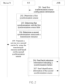
- FIG. 2 is a schematic interactive flowchart of a data transmission method according to an embodiment of the present invention.
- an access network device is an eNB and data is V2X data.
- information exchange between UE and an eNB and information exchange between the UE and a device X are used as examples for description of data transmission.
- the eNB sends first synchronization source configuration information to the UE on a first carrier, and the UE receives the first synchronization source configuration information sent by the eNB on the first carrier.
- the eNB sends the first synchronization source configuration information to the UE.
- the first synchronization source configuration information may be used to configure, for the UE, a current synchronization source required for transmitting V2X data on a second carrier.
- the first synchronization source configuration information carries an identifier of a first synchronization source, so that the UE determines, based on the identifier of the first synchronization source, the current synchronization source required for transmitting V2X data.
- the first synchronization source configuration information in this embodiment of the present invention may indicate that the first synchronization source is any one of a GNSS, a mobile terminal or a cell synchronized with a GNSS, a cell currently serving the UE, a specified cell, and a specified mobile terminal synchronization source.
- the first synchronization source configuration information may indicate that the first synchronization source is a GNSS, and correspondingly the identifier of the first synchronization source is a GNSS identifier.
- the eNB is deployed on the first carrier, and V2X data transmission is performed by using the second carrier.
- a frequency of the first carrier is different from a frequency of the second carrier.
- the frequency of the first carrier (a service carrier of the UE) may be 2 GHz
- the frequency of the second carrier (a transmission carrier used by the UE to transmit V2X data) may be 5.9 GHz.
- the service carrier may be used to configure a transmission resource (for example, a dynamic transmission resource, a semi-persistent transmission resource, a transmission resource pool, and a receiving resource pool) on the transmission carrier for the UE.
- the configuration information may further include frequency information of the second carrier, so that a first UE may perform data transmission on the frequency of the second carrier.
- no base station is deployed on the second carrier.
- the V2X data may be transmitted in a direct connection communication manner in which two devices directly communicate with each other, or may be transmitted in a communication manner in which a base station acts as a relay.
- the V2X data is transmitted on the second carrier in the direct connection communication manner.
- the eNB may send the configuration information to the UE by using radio resource control (Radio Resource Control, RRC) dedicated signaling or a broadcast message.
- RRC Radio Resource Control
- the UE may always be within a network coverage area of the eNB.
- the UE in a connected state may normally exchange signaling and data with the base station, and the UE in an idle state may normally receive system information and paging information sent by the base station.
- the UE determines a first synchronization source.
- the UE receives the first synchronization source configuration information, and uses, based on the first synchronization source configuration information, the first synchronization source as a synchronization source for transmitting the V2X data.
- the UE may determine the first synchronization source based on the identifier of the first synchronization source.
- the UE may further implement synchronization between the UE and the first synchronization source.
- the first synchronization source is a GNSS
- the UE may directly synchronize with the GNSS system by using a GNSS receiver of the UE, or may search for a GNSS-dedicated direct-connection link synchronization signal to use a mobile terminal with a GNSS clock as an intermediate synchronization source, and synchronize with the intermediate synchronization source to implement synchronization with the GNSS system.
- the UE may implement data transmission by using a corresponding resource and based on the synchronization source. For example, after synchronizing with the first synchronization source, the UE may receive resource allocation information sent by the base station.
- the resource allocation information indicates at least one of a dynamic transmission resource, a semi-persistent transmission resource, a sending resource pool, and a receiving resource pool that are available on a direct connection link.
- the resource allocation information herein is configured based on a clock of the first synchronization source.
- the UE transmits data by using a corresponding resource and based on the received resource allocation information. Specifically, the UE may send corresponding V2X data by using a sending resource and receive corresponding V2X data by using a receiving resource.
- the UE determines that synchronization with the first synchronization source fails.
- Step 202 indicates that the UE may implement data transmission by using a corresponding resource and based on the first synchronization source. However, the UE may be out of synchronization with the first synchronization source, for example, when the UE enters a tunnel or a garage.
- the UE may determine a failure of the synchronization with the first synchronization source by using many methods, and a specific determining method is not limited in this embodiment of the present invention.
- a synchronization timer on the UE may start timing when a latest synchronization signal is received. If the UE does not receive a synchronization signal from the first synchronization source when the synchronization timer of the UE exceeds a specified time, it may be considered that the synchronization between the UE and the first synchronization source fails.
- the UE may receive a synchronization signal from a synchronization source.
- a first preset threshold When strength of a synchronization signal received by the UE from the first synchronization source is less than a first preset threshold, it may be considered that the synchronization between the UE and the first synchronization source fails. For still another example, when average strength of synchronization signals received by the UE from the first synchronization source in specified duration T is less than a second preset threshold, it may be considered that the synchronization between the UE and the first synchronization source fails.
- the failure of the synchronization between the UE and the first synchronization source may be that the UE is out of synchronization with the first synchronization source.
- the UE detects a better synchronization source other than the first synchronization source it may also be considered that the synchronization between the UE and the first synchronization source fails. For example, when the UE detects a second synchronization source, signal strength of the second synchronization source is greater than a third preset threshold, and a priority of the second synchronization source is higher than a priority of the first synchronization source, the UE may determine that the synchronization with the first synchronization source fails.
- the UE determines that the synchronization with the first synchronization source fails.
- a priority of a synchronization source may be preconfigured by the system, or may be configured by the base station, for example, the base station sends system broadcast information to the UE on the first carrier for configuration, or the base station sends radio resource control RRC dedicated signaling to the UE on the first carrier for configuration.
- the UE determines a second synchronization source and a transmission resource.
- a transmission resource may be allocated based on a clock of the second synchronization source.
- the transmission resource herein may be configured by the base station or may be preconfigured by the system.
- the second synchronization source and a corresponding transmission resource may be obtained through preconfiguration or may be obtained by the base station through signaling configuration.
- the signaling configuration of the base station may be that the UE receives, on the first carrier, signaling configuration information sent by the base station.
- the UE may determine, in the following manner, the second synchronization source required for transmitting V2X data.
- the UE obtains second synchronization source configuration information sent by the access network device on the first carrier, the second synchronization source configuration information may carry an identifier of the second synchronization source, and the UE may determine, based on the identifier of the second synchronization source, the second synchronization source required for transmitting V2X data.
- the second synchronization source configuration information sent by the access network device to the UE may be configured by using a broadcast message or may be configured by sending radio resource control RRC dedicated signaling.
- the UE may obtain, by using preconfigured information, second synchronization source configuration information that carries an identifier of the second synchronization source, and determine, based on the identifier of the second synchronization source, the second synchronization source required for transmitting V2X data.
- the UE may use a clock of the UE as the second synchronization source.
- the clock of the UE may be a clock or a timer currently independently maintained inside the UE.
- the UE may use a clock of the current base station as the clock of the UE, or may independently determine a clock as the clock of the UE.
- the UE may determine, in the following manner, a transmission resource required for transmitting V2X data.
- the UE obtains resource pool configuration information, determines a transmission resource pool based on the transmission resource pool configuration information, and determines the transmission resource based on the transmission resource pool.
- the resource pool configuration information may be preconfigured information, or may be configured by the access network device by using signaling.
- the resource pool configuration information indicates available transmission resource pools, for example, a receiving resource pool or a sending resource pool.
- the UE may randomly select one resource pool from the available resource pools, and select one resource from the selected resource pool as the transmission resource for transmitting the data on the second carrier, in other words, performing corresponding data transmission or reception.
- the transmission resource in this embodiment of the present invention may be a dynamic transmission resource or a semi-persistent transmission resource.
- the UE may alternatively determine, in the following manner, the transmission resource required for transmitting V2X data.
- the UE receives resource scheduling information sent by the access network device, and determines the transmission resource based on the resource scheduling information, so that the UE may transmit the data on the second carrier by using the determined transmission resource and based on the second synchronization source.
- the resource scheduling information herein is used for dynamic resource scheduling or semi-persistent resource scheduling.
- a resource number during first scheduling may be specified, and a change rule or period of a resource number during each scheduling may be specified, so as to perform semi-persistent resource scheduling at intervals of a specified quantity of resources.
- the dynamic resource scheduling in this embodiment of the present invention means that a resource is dynamically scheduled each time the resource is used.
- the UE determines the transmission resource by using the clock of the second synchronization source as a reference synchronization clock.
- the UE transmits data on a transmission carrier (for example, a second carrier) by using the transmission resource and based on the second synchronization source determined in step 204, and the device X receives, on the second carrier, the data transmitted by the UE.
- a transmission carrier for example, a second carrier
- that the UE transmits data on the transmission carrier may be that the UE sends data or that the UE receives data.
- a corresponding transmission resource may be a sending resource or a receiving resource.
- the UE transmits the data on the second carrier is that the UE performs data transmission with another device (for example, the device X).
- the UE in this embodiment of the present invention may be an in-vehicle device, and the device X may be an in-vehicle device, a network, a roadside infrastructure, a handheld terminal of a pedestrian, or the like.
- Data transmitted between the UE and the device X may be V2X data.
- the UE sends, to the eNB, indication information indicating that synchronization fails, and the eNB receives the indication information indicating that synchronization fails, which is sent by the UE.
- Step 206 is an optional step.
- the UE may feed back the indication information to the eNB, and the indication information is used to indicate that the synchronization between the UE and the first synchronization source fails.
- the UE feeds back a synchronization failure to the eNB, so that the eNB does not need to send signaling, a configuration resource, and the like to the UE, so as to reduce signaling overheads.
- the eNB may also send new synchronization source configuration information to the eNB, and optionally, the new synchronization source configuration information may be the second synchronization source configuration information.
- step 206 may be performed before step 204 in which the new second synchronization source is re-determined, or step 206 may be performed after step 204, or step 206 and step 204 may be performed at the same time. This is not limited in this embodiment of the present invention.
- the UE sends identification information of the second synchronization source to the eNB, and the eNB receives the identification information of the second synchronization source, which is sent by the UE.
- Step 207 is an optional step.
- the UE may further send the identification information of the second synchronization source to the eNB.
- the identification information of the second synchronization source may carry the identifier of the second synchronization source, and may be used to instruct the UE to use the clock of the second synchronization source as a synchronization clock required for transmitting the data on the second carrier.
- the eNB may record related information of a current synchronization source (the second synchronization source) of the UE in the eNB, so that the eNB obtains a new synchronization source and uses a clock of the new synchronization source as a synchronization clock for resource configuration.
- the data in this embodiment of the present invention may be V2X data.
- user equipment determines, based on synchronization source information configured by a base station, a synchronization source required for transmitting data. After being out of synchronization with the synchronization source, the UE re-determines a new synchronization source, and uses the new synchronization source for data transmission. In this way, when frequencies of a transmission carrier and a service carrier are different, normal data transmission can still be implemented after the UE is out of synchronization with an original synchronization source.
- step 207 may be performed at any moment after step 204 in which the new second synchronization source is re-determined, for example, step 207 is performed before or after step 205 in which data is transmitted, or step 207 and step 205 are performed at the same time. This is not limited in this embodiment of the present invention.
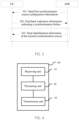
- FIG. 3 is a schematic interactive flowchart of a data transmission method according to another embodiment of the present invention.
- an access network device is an eNB
- V2X data is transmitted
- information is exchanged between UE and the eNB.
- the eNB sends first synchronization source configuration information to the user equipment UE on a first carrier, and the UE receives the first synchronization source configuration information sent by the eNB on the first carrier.
- the first synchronization source configuration information may carry an identifier of a first synchronization source.
- the eNB is deployed on the first carrier.
- the UE (for example, an eNB) receives the first synchronization source configuration information sent by a base station.
- the UE may synchronize with the first synchronization source based on the first synchronization source configuration information, and transmit data on a second carrier based on the first synchronization source.
- the UE sends indication information to the eNB on the first carrier, and the eNB receives, on the first carrier, the indication information sent by the UE.
- the indication information is used to indicate that the synchronization between the UE and the first synchronization source fails. After detecting that the synchronization with the first synchronization source fails, the UE may send the indication information to the eNB.
- the UE may send the indication information to the eNB.
- a method for determining a synchronization failure by the UE refer to description in step 203 in FIG. 2 . Details are not described herein again to avoid repetition.
- the access network device in this embodiment of the present invention configures a synchronization source for the UE, and after synchronization between the UE and the synchronization source fails, receives indication information that is sent by the UE and that indicates that the synchronization with the synchronization source fails. In this way, after the synchronization between the UE and the synchronization source fails, based on the indication information, the access network device may skip sending signaling to the UE or configuring a resource corresponding to the first synchronization source for the UE, so as to save a signaling overhead.
- the eNB may send second synchronization source configuration information to the UE on the first carrier, and the UE receives, on the first carrier, the second synchronization source configuration information sent by the eNB.
- the second synchronization source configuration information is used by the UE to determine a second synchronization source based on the second synchronization source configuration information after the synchronization with the first synchronization source fails, and transmit the data on the second carrier based on the second synchronization source.
- a frequency of the first carrier is different from a frequency of the second carrier.
- Step 303 is an optional step.
- the eNB may reconfigure a synchronization source for the UE, for example, by sending the second synchronization source configuration information to the UE on the first carrier.
- the second synchronization source configuration information may include an identifier of the second synchronization source.
- the UE may synchronize with the second synchronization source based on the second synchronization source configuration information, so as to continue to transmit the data on the second carrier based on the second synchronization source, and ensure normal data transmission.
- the eNB may receive identification information that is of the second synchronization source and that is sent by the UE, so that the base station obtains an identifier of a new synchronization source (the second synchronization source), and configures a transmission resource corresponding to the second synchronization source for the second synchronization source.
- Step 303 is an optional step.
- the access network device may further send the second synchronization source configuration information to the UE on the first carrier.
- the second synchronization source configuration information is used by the UE to determine the second synchronization source based on the second synchronization source configuration information after the synchronization with the first synchronization source fails, and transmit the data on the second carrier based on the second synchronization source.
- the frequency of the first carrier is different from the frequency of the second carrier.
- the access network device can learn of a new synchronization source (for example, the second synchronization source), so as to configure a transmission resource corresponding to the second synchronization source for the second synchronization source.
- a new synchronization source for example, the second synchronization source
- the access network device may configure, for the UE, a transmission resource corresponding to the second synchronization source, and send the transmission resource to the UE, so that the UE transmits data on the transmission resource based on the second synchronization source. In this way, the UE can still perform normal data transmission after the synchronization with the first synchronization source fails.
- the data is vehicle-to-everything V2X communication data.
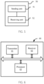
- FIG. 4 is a block diagram of a data transmission apparatus according to an embodiment of the present invention.
- the apparatus in FIG. 4 may perform steps performed by the UE in the method embodiment in FIG. 2 .
- An apparatus 40 in FIG. 4 includes a receiving unit 41, a processing unit 42 and a transmission unit 43.
- the receiving unit 41 is configured to receive first synchronization source configuration information on a first carrier, where the first synchronization source configuration information is used to determine a first synchronization source.
- the processing unit 42 is configured to: determine the first synchronization source based on the first synchronization source configuration information received by the receiving unit; determine that synchronization with the first synchronization source fails; and determine a second synchronization source and a transmission resource.
- the first synchronization source is used to provide a synchronization clock required for transmitting data on a second carrier, and a frequency of the first carrier is different from a frequency of the second carrier.
- the transmission unit 43 is configured to transmit the data on the second carrier by using the transmission resource and based on the second synchronization source determined by the processing unit.
- the user equipment determines, based on synchronization source information configured by a base station, a synchronization source required for transmitting data. After being out of synchronization with the synchronization source, the UE re-determines a new synchronization source, and uses the new synchronization source for data transmission. In this way, when frequencies of a transmission carrier and a service carrier are different, normal data transmission can still be implemented after the UE is out of synchronization with an original synchronization source.
- the data transmission apparatus in this embodiment of the present invention may be applied to specific steps and an execution procedure of the UE in the data transmission method of the embodiments of the present invention, and units/modules of the apparatus and other operations and/or functions described above are respectively for implementing corresponding procedures of the UE in the method shown in FIG. 2 . Details are not described herein again for brevity.
- the receiving unit may be a receiver
- the processing unit may be a processor
- the transmission unit can be a transmitter.
- the receiver, the processor, and the transmitter may be configured to respectively perform methods performed by the receiving unit, the processing unit, and the transmission unit. Details are not described again to avoid repetition.
- FIG. 5 is a block diagram of a data transmission apparatus according to another embodiment of the present invention.
- the apparatus in FIG. 5 may perform steps performed by the eNB in the method embodiments in FIG. 2 and FIG. 3 .
- An apparatus 50 in FIG. 5 includes a sending unit 51 and a receiving unit 52.
- the sending unit 51 is configured to send first synchronization source configuration information to user equipment UE by using a first carrier.
- the first synchronization source configuration information carries an identifier of a first synchronization source, and the first configuration information is used to determine the first synchronization source.
- the receiving unit 52 is configured to receive indication information sent by the UE.
- the indication information is used to indicate that synchronization between the UE and the first synchronization source fails.
- the first synchronization source is used to provide the UE with a synchronization clock required for transmitting data on a second carrier. A frequency of the first carrier is different from a frequency of the second carrier.
- the access network device configures a synchronization source for the UE, and after synchronization between the UE and the synchronization source fails, may receive indication information that is sent by the UE and that indicates that the synchronization with the synchronization source fails. In this way, after the synchronization between the UE and the synchronization source fails, based on the indication information, the access network device may skip sending signaling to the UE or configuring a resource corresponding to the first synchronization source for the UE, so as to save a signaling overhead.
- the sending unit 51 is further configured to send second synchronization source configuration information to the UE on the first carrier.
- the second synchronization source configuration information is used by the UE to determine a second synchronization source based on the second synchronization source configuration information after the synchronization with the first synchronization source fails, and transmit the data on the second carrier based on the second synchronization source.
- the eNB may reconfigure a synchronization source for the UE after receiving the indication information indicating a synchronization failure, for example, send the second synchronization source configuration information to the UE on the first carrier.
- the second synchronization source configuration information may include an identifier of the second synchronization source.
- the UE may synchronize with the second synchronization source based on the second synchronization source configuration information, so as to continue to transmit the data on the second carrier based on the second synchronization source, and ensure normal data transmission.
- the data transmission apparatus in this embodiment of the present invention may be applied to specific steps and an execution procedure of the eNB in the data transmission method of the embodiments of the present invention, and units/modules of the apparatus and other operations and/or functions described above are respectively for implementing corresponding procedures of the eNB in the method shown in FIG. 3 . Details are not described herein again for brevity.
- the receiving unit may be a receiver and the sending unit may be a transmitter.
- the receiver and the transmitter may be configured to respectively perform methods performed by the receiving unit and the sending unit. Details are not described again to avoid repetition.
- FIG. 6 is a block diagram of a data transmission apparatus according to another embodiment of the present invention.
- An apparatus 60 in FIG. 6 includes a transmitter 61, a receiver 62, and a processor 63.
- the processor 63 controls an operation of the apparatus 60 and may be configured to process a signal.
- the method disclosed in the foregoing embodiments of the present invention may be applied to the processor 63, or may be implemented by the processor 43. In an implementation process, steps in the foregoing method may be completed by using an integrated logic circuit of hardware or an instruction in a form of software in the processor 63.
- the processor 63 may be a general-purpose processor, a digital signal processor, an application-specific integrated circuit, a field programmable gate array or another programmable logic device, a discrete gate or a transistor logic device, or a discrete hardware component, and may implement or perform methods, steps, and logic block diagrams that are disclosed in the embodiments of the present invention.
- the general-purpose processor may be a microprocessor, any conventional processor, or the like.
- the steps of the methods disclosed with reference to the embodiments of the present invention may be directly implemented by using a hardware processor, or may be implemented by using a combination of hardware and a software module in the processor.
- the receiver 62 may receive first synchronization source configuration information on a first carrier.
- the first synchronization source configuration information is used to determine a first synchronization source.
- the processor 63 may determine the first synchronization source based on the first synchronization source configuration information; determine that synchronization with the first synchronization source fails; and determine a second synchronization source and a transmission resource.
- the first synchronization source is used to provide UE with a synchronization clock required for transmitting data on a second carrier.
- a frequency of the first carrier is different from a frequency of the second carrier.
- the transmitter 61 may transmit the data on the second carrier by using the transmission resource and based on the second synchronization source.
- user equipment determines, based on synchronization source information configured by a base station, a synchronization source required for transmitting data. After being out of synchronization with the synchronization source, the UE re-determines a new synchronization source, and uses the new synchronization source for data transmission. In this way, when frequencies of a transmission carrier and a service carrier are different, normal data transmission can still be implemented after the UE is out of synchronization with an original synchronization source.
- the data transmission apparatus in this embodiment of the present invention may be applied to specific steps and an execution procedure of the UE in the data transmission method of the embodiments of the present invention, and units/modules of the apparatus and other operations and/or functions described above are respectively for implementing corresponding procedures of the UE in the method shown in FIG. 2 . Details are not described herein again for brevity.
- FIG. 7 is a block diagram of a data transmission apparatus according to another embodiment of the present invention.
- An apparatus 70 in FIG. 7 includes a transmitter 71 and a receiver 72.
- the transmitter 71 may send first synchronization source configuration information to user equipment UE by using a first carrier, where the first synchronization source configuration information carries an identifier of a first synchronization source, and the first synchronization source configuration information is used to determine the first synchronization source.
- the receiver 72 may receive indication information sent by the UE.
- the indication information is used to indicate that synchronization between the UE and the first synchronization source fails.
- the first synchronization source is used to provide the UE with a synchronization clock required for transmitting data on a second carrier. A frequency of the first carrier is different from a frequency of the second carrier.
- the access network device in this embodiment of the present invention configures a synchronization source for the UE, and after synchronization between the UE and the synchronization source fails, receives indication information that is sent by the UE and that indicates that the synchronization with the synchronization source fails. In this way, after the synchronization between the UE and the synchronization source fails, based on the indication information, the access network device may skip sending signaling to the UE or configuring a resource corresponding to the first synchronization source for the UE, so as to save a signaling overhead.
- the transmitter 71 may further be configured to send second synchronization source configuration information to the UE on the first carrier.
- the second synchronization source configuration information is used by the UE to determine a second synchronization source based on the second synchronization source configuration information after the synchronization with the first synchronization source fails, and transmit the data on the second carrier based on the second synchronization source.
- the data transmission apparatus in this embodiment of the present invention may be applied to specific steps and an execution procedure of the eNB in the data transmission method of the embodiments of the present invention, and units/modules of the apparatus and other operations and/or functions described above are respectively for implementing corresponding procedures of the eNB in the method shown in FIG. 3 . Details are not described herein again for brevity.
- an embodiment mentioned in the whole specification does not mean that particular features, structures, or characteristics related to the embodiment are included in at least one embodiment of the present invention. Therefore, “in an embodiment” or “in an embodiment” appearing throughout the specification does not refer to a same embodiment. In addition, these particular features, structures, or characteristics may be combined in one or more embodiments by using any appropriate manner.
- sequence numbers of the foregoing processes do not mean execution sequences in various embodiments of the present invention.
- the execution sequences of the processes should be determined according to functions and internal logic of the processes, and should not be construed as any limitation on the implementation processes of the embodiments of the present invention.
- B corresponding to A indicates that B is associated with A, and B may be determined based on A.
- determining A based on B does not mean that B is determined based on A only; in other words, B may be determined based on A and/or other information.
- the disclosed system, apparatus, and method may be implemented in other manners.
- the described apparatus embodiment is merely an example.
- the unit division is merely logical function division and may be other division in actual implementation.
- a plurality of units or components may be combined or integrated into another system, or some features may be ignored or not performed.
- the displayed or discussed mutual couplings or direct couplings or communication connections may be implemented by using some interfaces.
- the indirect couplings or communication connections between the apparatuses or units may be implemented in electronic, mechanical, or other forms.
- the units described as separate parts may or may not be physically separate, and parts displayed as units may or may not be physical units, may be located in one position, or may be distributed on a plurality of network units. Some or all of the units may be selected based on actual requirements to achieve the objectives of the solutions of the embodiments.
- functional units in the embodiments of the present invention may be integrated into one processing unit, or each of the units may exist alone physically, or two or more units are integrated into one unit.
- the functions When the functions are implemented in the form of a software functional unit and sold or used as an independent product, the functions may be stored in a computer-readable storage medium. Based on such an understanding, the technical solutions of the present invention essentially, or the part contributing to the prior art, or some of the technical solutions may be implemented in a form of a software product.
- the computer software product is stored in a storage medium, and includes several instructions for instructing a computer device (which may be a personal computer, a server, or a network device) to perform all or some of the steps of the methods described in the embodiments of the present invention.
- the foregoing storage medium includes: any medium that can store program code, such as a USB flash drive, a removable hard disk, a read-only memory (Read-Only Memory, ROM), a random access memory (Random Access Memory, RAM), a magnetic disk, or an optical disc.
- program code such as a USB flash drive, a removable hard disk, a read-only memory (Read-Only Memory, ROM), a random access memory (Random Access Memory, RAM), a magnetic disk, or an optical disc.
Landscapes
- Engineering & Computer Science (AREA)
- Computer Networks & Wireless Communication (AREA)
- Signal Processing (AREA)
- Mobile Radio Communication Systems (AREA)
Claims (15)
- Datenübertragungsverfahren, das Folgendes umfasst:Empfangen (201), durch eine Benutzereinrichtung bzw. UE, von ersten Synchronisationsquellenkonfigurationsinformationen auf einem ersten Träger, wobei die ersten Synchronisationsquellenkonfigurationsinformationen zum Bestimmen einer ersten Synchronisationsquelle verwendet werden;Bestimmen (202), durch die UE, der ersten Synchronisationsquelle basierend auf den ersten Synchronisationsquellenkonfigurationsinformationen, wobei die erste Synchronisationsquelle zum Bereitstellen eines zur Übertragung von Daten auf einem zweiten Träger für die UE erforderlichen Synchronisationstakts verwendet wird und sich eine Frequenz des ersten Trägers von einer Frequenz des zweiten Trägers unterscheidet;Bestimmen (204), durch die UE, einer zweiten Synchronisationsquelle und einer Übertragungsressource, wobei die Übertragungsressource mit der zweiten Synchronisationsquelle assoziiert ist, Bestimmen (203), durch die UE, dass eine Synchronisation mit der ersten Synchronisationsquelle fehlschlägt, wenn die Signalstärke der zweiten Synchronisationsquelle größer als eine erste voreingestellte Schwelle ist und eine Signalstärke der ersten Synchronisationsquelle kleiner als eine zweite Schwelle ist und eine Priorität der zweiten Synchronisationsquelle gleich oder kleiner als eine Priorität der ersten Synchronisationsquelle ist; undÜbertragen (205), durch die UE, der Daten auf der Übertragungsressource des zweiten Trägers und basierend auf der zweiten Synchronisationsquelle.
- Verfahren nach Anspruch 1, wobei das Bestimmen (203), durch die UE, dass eine Synchronisation mit der ersten Synchronisationsquelle fehlschlägt, eine beliebige der folgenden Weisen umfasst:wenn die UE kein Synchronisationssignal von der ersten Synchronisationsquelle empfängt, wenn ein Synchronisationstimer der UE eine vorgegebene Zeit überschreitet, Bestimmen, durch die UE, dass die Synchronisation mit der ersten Synchronisationsquelle fehlschlägt; oderwenn eine durchschnittliche Stärke von durch die UE von der ersten Synchronisationsquelle in einer vorgegebenen Dauer T empfangenen Synchronisationssignalen kleiner als die zweite voreingestellte Schwelle ist, Bestimmen, durch die UE, dass die Synchronisation mit der ersten Synchronisationsquelle fehlschlägt.
- Verfahren nach einem der Ansprüche 1 bis 2, wobei das Bestimmen (204), durch die UE, einer zweiten Synchronisationsquelle und einer Übertragungsressource Folgendes umfasst:Erhalten, durch die UE, von Ressourcenpoolkonfigurationsinformationen, wobei die Ressourcenpoolkonfigurationsinformationen vorkonfiguriert sind oder die Ressourcenpoolkonfigurationsinformationen basierend auf auf dem ersten Träger empfangenen Signalisierungskonfigurationsinformationen erhalten werden; undBestimmen, durch die UE, eines Übertragungsressourcenpools basierend auf den Ressourcenpoolkonfigurationsinformationen und Bestimmen der Übertragungsressource basierend auf dem Übertragungsressourcenpool.
- Verfahren nach einem der Ansprüche 1 bis 3, das ferner Folgendes umfasst:
Senden, durch die UE auf dem ersten Träger, von Identifikationsinformationen der zweiten Synchronisationsquelle an die Zugangsnetzvorrichtung, wobei die Identifikationsinformationen der zweiten Synchronisationsquelle zum Angeben einer aktuellen Synchronisationsquelle der UE verwendet werden. - Verfahren nach einem der Ansprüche 1 bis 4, wobei die erste Synchronisationsquelle ein globales Navigationssatellitensystem bzw. GNSS ist.
- Verfahren nach einem der Ansprüche 1 bis 5, wobei das Übertragen (205), durch die UE, der Daten auf der Übertragungsressource des zweiten Trägers und basierend auf der zweiten Synchronisationsquelle Folgendes umfasst:
Übertragen, durch die UE, der Daten auf eine Direktverbindungskommunikationsweise auf der Übertragungsressource des zweiten Trägers basierend auf der zweiten Synchronisationsquelle. - Verfahren nach einem der Ansprüche 1 bis 6, wobei es sich bei den Daten um "Vehicle-to-Everything"- bzw. V2X-Kommunikationsdaten handelt.
- Datenübertragungsvorrichtung, die Folgendes umfasst:eine Empfangseinheit (41), ausgelegt zum Empfangen von ersten Synchronisationsquellenkonfigurationsinformationen auf einem ersten Träger, wobei die ersten Synchronisationsquellenkonfigurationsinformationen zum Bestimmen einer ersten Synchronisationsquelle verwendet werden;eine Verarbeitungseinheit (42), ausgelegt zum Bestimmen der ersten Synchronisationsquelle basierend auf den durch die Empfangseinheit (41) empfangenen ersten Synchronisationsquellenkonfigurationsinformationen, wobei die erste Synchronisationsquelle zum Bereitstellen eines zur Übertragung von Daten auf einem zweiten Träger erforderlichen Synchronisationstakts verwendet wird und sich eine Frequenz des ersten Trägers von einer Frequenz des zweiten Trägers unterscheidet, wobeidie Verarbeitungseinheit (42) ferner ausgelegt ist zum Bestimmen einer zweiten Synchronisationsquelle und einer Übertragungsressource, wobei die Übertragungsressource mit der zweiten Synchronisationsquelle assoziiert ist, die Verarbeitungseinheit (42) ferner ausgelegt ist zum Bestimmen, dass eine Synchronisation mit der ersten Synchronisationsquelle fehlschlägt, wenn die Signalstärke der zweiten Synchronisationsquelle größer als eine erste voreingestellte Schwelle ist und eine Signalstärke der ersten Synchronisationsquelle kleiner als eine zweite Schwelle ist und eine Priorität der zweiten Synchronisationsquelle gleich oder kleiner als eine Priorität der ersten Synchronisationsquelle ist; undeine Übertragungseinheit (43), ausgelegt zum Übertragen der Daten auf der Übertragungsressource des zweiten Trägers und basierend auf der durch die Verarbeitungseinheit (42) bestimmten zweiten Synchronisationsquelle.
- Vorrichtung nach Anspruch 8, wobei die Verarbeitungseinheit (42) insbesondere ausgelegt ist zum Bestimmen, auf eine beliebige der folgenden Weisen, dass die Synchronisation mit der ersten Synchronisationsquelle fehlschlägt: wenn kein Synchronisationssignal von der ersten Synchronisationsquelle empfangen wird, bevor ein Synchronisationstimer eine vorgegebene Zeit überschreitet, Bestimmen, dass die Synchronisation mit der ersten Synchronisationsquelle fehlschlägt; und wenn eine durchschnittliche Stärke von von der ersten Synchronisationsquelle in einer vorgegebenen Dauer T empfangenen Synchronisationssignalen kleiner als die zweite voreingestellte Schwelle ist, Bestimmen, dass die Synchronisation mit der ersten Synchronisationsquelle fehlschlägt.
- Vorrichtung nach einem der Ansprüche 8 bis 9, wobei die Verarbeitungseinheit (42) insbesondere zu Folgendem ausgelegt ist: Erhalten von Ressourcenpoolkonfigurationsinformationen, wobei die Ressourcenpoolkonfigurationsinformationen vorkonfiguriert sind oder die Ressourcenpoolkonfigurationsinformationen basierend auf auf dem ersten Träger empfangenen Signalisierungskonfigurationsinformationen erhalten werden; Bestimmen eines Übertragungsressourcenpools basierend auf den Ressourcenpoolkonfigurationsinformationen, und Bestimmen der Übertragungsressource basierend auf dem Übertragungsressourcenpool.
- Vorrichtung nach einem der Ansprüche 8 bis 10, wobei die Vorrichtung eine Benutzereinrichtung bzw. UE ist und die Übertragungseinheit (43) ferner ausgelegt ist zum Senden von Identifikationsinformationen der zweiten Synchronisationsquelle an die Zugangsnetzvorrichtung, wobei die Identifikationsinformationen der zweiten Synchronisationsquelle zum Angeben einer aktuellen Synchronisationsquelle der UE verwendet werden.
- Vorrichtung nach einem der Ansprüche 8 bis 11, wobei die erste Synchronisationsquelle ein globales Navigationssatellitensystem bzw. GNSS ist.
- Vorrichtung nach einem der Ansprüche 8 bis 12, wobei die Übertragungseinheit (43) insbesondere ausgelegt ist zum Übertragen von Daten auf eine Direktverbindungskommunikationsweise auf der Übertragungsressource des zweiten Trägers basierend auf der zweiten Synchronisationsquelle.
- Vorrichtung nach einem der Ansprüche 8 bis 13, wobei es sich bei den Daten um "Vehicle-to-Everything"- bzw. V2X-Kommunikationsdaten handelt.
- Computerprogramm, das Anweisungen umfasst, wobei die Anweisungen bei Ausführung durch einen Computer bewirken, dass der Computer das Verfahren nach einem der Ansprüche 1 bis 7 durchführt.
Priority Applications (1)
| Application Number | Priority Date | Filing Date | Title |
|---|---|---|---|
| EP20214795.5A EP3855814B1 (de) | 2016-08-11 | 2016-08-11 | Datenübertragungsverfahren und vorrichtung |
Applications Claiming Priority (3)
| Application Number | Priority Date | Filing Date | Title |
|---|---|---|---|
| EP20214795.5A EP3855814B1 (de) | 2016-08-11 | 2016-08-11 | Datenübertragungsverfahren und vorrichtung |
| PCT/CN2016/094607 WO2018027790A1 (zh) | 2016-08-11 | 2016-08-11 | 传输数据的方法和装置 |
| EP16912245.4A EP3484217B1 (de) | 2016-08-11 | 2016-08-11 | Verfahren und vorrichtung zur datenübertragung |
Related Parent Applications (2)
| Application Number | Title | Priority Date | Filing Date |
|---|---|---|---|
| EP16912245.4A Division EP3484217B1 (de) | 2016-08-11 | 2016-08-11 | Verfahren und vorrichtung zur datenübertragung |
| EP16912245.4A Division-Into EP3484217B1 (de) | 2016-08-11 | 2016-08-11 | Verfahren und vorrichtung zur datenübertragung |
Publications (2)
| Publication Number | Publication Date |
|---|---|
| EP3855814A1 EP3855814A1 (de) | 2021-07-28 |
| EP3855814B1 true EP3855814B1 (de) | 2025-02-19 |
Family
ID=61161564
Family Applications (2)
| Application Number | Title | Priority Date | Filing Date |
|---|---|---|---|
| EP20214795.5A Active EP3855814B1 (de) | 2016-08-11 | 2016-08-11 | Datenübertragungsverfahren und vorrichtung |
| EP16912245.4A Active EP3484217B1 (de) | 2016-08-11 | 2016-08-11 | Verfahren und vorrichtung zur datenübertragung |
Family Applications After (1)
| Application Number | Title | Priority Date | Filing Date |
|---|---|---|---|
| EP16912245.4A Active EP3484217B1 (de) | 2016-08-11 | 2016-08-11 | Verfahren und vorrichtung zur datenübertragung |
Country Status (6)
| Country | Link |
|---|---|
| US (2) | US12047891B2 (de) |
| EP (2) | EP3855814B1 (de) |
| JP (1) | JP6886511B2 (de) |
| KR (1) | KR102209453B1 (de) |
| CN (2) | CN109479248B (de) |
| WO (1) | WO2018027790A1 (de) |
Families Citing this family (12)
| Publication number | Priority date | Publication date | Assignee | Title |
|---|---|---|---|---|
| WO2019127283A1 (zh) * | 2017-12-28 | 2019-07-04 | Oppo广东移动通信有限公司 | 无线通信的方法、终端设备和网络设备 |
| US12150074B2 (en) | 2019-07-18 | 2024-11-19 | Lg Electronics Inc. | Method and apparatus for selecting synchronization reference in NR V2X |
| US11757706B2 (en) * | 2019-07-19 | 2023-09-12 | Razberi Secure Technologies, Llc | Switch monitoring system and method of use |
| US11696241B2 (en) * | 2019-07-30 | 2023-07-04 | Qualcomm Incorporated | Techniques for synchronizing based on sidelink synchronization signal prioritization |
| KR20220149687A (ko) * | 2020-03-02 | 2022-11-08 | 광동 오포 모바일 텔레커뮤니케이션즈 코포레이션 리미티드 | 동기화 방법 및 장치 |
| CN114915988B (zh) * | 2021-02-10 | 2025-12-19 | 维沃移动通信有限公司 | 信息传输方法、通信设备及存储介质 |
| US11663907B2 (en) | 2021-06-21 | 2023-05-30 | Ettifos Co. | Method and apparatus for transmitting and receiving vehicle-to-pedestrian (V2P) message |
| KR102354630B1 (ko) * | 2021-06-21 | 2022-01-25 | 에티포스 시오 | V2p 메시지를 송수신하기 위한 방법 및 장치 |
| CN115515215B (zh) * | 2021-06-22 | 2025-04-18 | 大唐移动通信设备有限公司 | 时钟同步方法、装置、设备及产品 |
| CN118104329A (zh) * | 2021-12-30 | 2024-05-28 | Oppo广东移动通信有限公司 | 无线通信的方法、终端设备和网络设备 |
| WO2024045020A1 (en) * | 2022-08-31 | 2024-03-07 | Qualcomm Incorporated | Sidelink timing synchronization enhancements |
| CN120111645B (zh) * | 2025-03-11 | 2025-09-19 | 广东博纬通信科技有限公司 | 一种基于EMM information消息的基站授时方法及系统 |
Family Cites Families (20)
| Publication number | Priority date | Publication date | Assignee | Title |
|---|---|---|---|---|
| US20090286569A1 (en) * | 2008-05-19 | 2009-11-19 | Nokia Corporation | Apparatus method and computer program for interference reduction |
| EP2991261B1 (de) * | 2011-05-31 | 2023-12-06 | NEC Corporation | Synchronisationsvorrichtung und synchronisationsverfahren |
| US9036550B2 (en) * | 2011-09-14 | 2015-05-19 | Electronics And Telecommunications Research Institute | Method and terminal for direct communication between terminals |
| JP2014143608A (ja) * | 2013-01-24 | 2014-08-07 | Ntt Docomo Inc | 無線通信システム、無線通信方法、無線基地局及びユーザ端末 |
| EP2995133B1 (de) * | 2013-05-06 | 2018-09-05 | Intel IP Corporation | Zugangsnetzerkennung und -auswahl |
| CN103828398A (zh) | 2013-07-26 | 2014-05-28 | 华为终端有限公司 | 同步信号的承载方法和用户设备 |
| JP5864034B2 (ja) * | 2013-10-11 | 2016-02-17 | 京セラ株式会社 | 通信制御方法、ユーザ端末及び通信装置 |
| US9572171B2 (en) * | 2013-10-31 | 2017-02-14 | Intel IP Corporation | Systems, methods, and devices for efficient device-to-device channel contention |
| WO2015066524A1 (en) * | 2013-10-31 | 2015-05-07 | Huawei Technologies Co., Ltd. | System and method for device-to-device synchronization |
| WO2015116940A1 (en) * | 2014-01-31 | 2015-08-06 | Intel Corporation | Systems, methods, and devices for synchronization and resource allocation for device-to-device communication |
| US10813068B2 (en) * | 2014-05-08 | 2020-10-20 | Apple Inc. | Systems, methods, and devices for synchronization source selection for device-to-device communication |
| CN106464396B (zh) * | 2014-05-09 | 2020-08-14 | 太阳专利信托公司 | 设备到设备同步源选择 |
| WO2015194859A1 (ko) * | 2014-06-17 | 2015-12-23 | 엘지전자 주식회사 | 무선 통신 시스템에서 단말 간 직접 통신을 위한 동기 신호를 수신하는 방법 및 이를 위한 장치 |
| WO2016019529A1 (zh) * | 2014-08-06 | 2016-02-11 | 华为技术有限公司 | 同步通信的方法和通信节点 |
| WO2016036182A1 (ko) * | 2014-09-05 | 2016-03-10 | 엘지전자 주식회사 | 무선 통신 시스템에서 디바이스들 간의 통신을 수행하는 방법 및 이를 수행하는 장치 |
| WO2017024541A1 (zh) * | 2015-08-12 | 2017-02-16 | 华为技术有限公司 | 同步通信方法及终端 |
| US20170054204A1 (en) * | 2015-08-21 | 2017-02-23 | Laird Technologies, Inc. | V2x antenna systems |
| US10652846B2 (en) * | 2015-09-24 | 2020-05-12 | Intel Corporation | Systems, methods and devices for cellular synchronization references |
| EP3404970A4 (de) * | 2016-01-15 | 2019-08-14 | LG Electronics Inc. -1- | Zeitsynchronisationsverfahren für v2v-endgerät |
| EP3442283B1 (de) * | 2016-05-12 | 2023-10-04 | Huawei Technologies Co., Ltd. | Informationsübertragungsverfahren und benutzergerät |
-
2016
- 2016-08-11 EP EP20214795.5A patent/EP3855814B1/de active Active
- 2016-08-11 WO PCT/CN2016/094607 patent/WO2018027790A1/zh not_active Ceased
- 2016-08-11 EP EP16912245.4A patent/EP3484217B1/de active Active
- 2016-08-11 CN CN201680087663.9A patent/CN109479248B/zh active Active
- 2016-08-11 KR KR1020197005749A patent/KR102209453B1/ko active Active
- 2016-08-11 JP JP2019507131A patent/JP6886511B2/ja active Active
- 2016-08-11 CN CN201910506946.8A patent/CN110278606B/zh active Active
-
2019
- 2019-02-11 US US16/271,954 patent/US12047891B2/en active Active
-
2024
- 2024-07-08 US US18/765,596 patent/US20240365263A1/en active Pending
Also Published As
| Publication number | Publication date |
|---|---|
| WO2018027790A1 (zh) | 2018-02-15 |
| EP3484217A1 (de) | 2019-05-15 |
| KR20190034603A (ko) | 2019-04-02 |
| US20240365263A1 (en) | 2024-10-31 |
| CN110278606B (zh) | 2020-07-24 |
| US20190174444A1 (en) | 2019-06-06 |
| JP2019531004A (ja) | 2019-10-24 |
| EP3855814A1 (de) | 2021-07-28 |
| CN109479248A (zh) | 2019-03-15 |
| US12047891B2 (en) | 2024-07-23 |
| CN109479248B (zh) | 2021-01-29 |
| JP6886511B2 (ja) | 2021-06-16 |
| CN110278606A (zh) | 2019-09-24 |
| EP3484217B1 (de) | 2021-02-24 |
| KR102209453B1 (ko) | 2021-01-28 |
| EP3484217A4 (de) | 2019-06-05 |
Similar Documents
| Publication | Publication Date | Title |
|---|---|---|
| US20240365263A1 (en) | Data transmission method and apparatus | |
| EP3432662B1 (de) | Verfahren und vorrichtung zur konfigurierung und bestimmung einer semipersistenten planung | |
| EP3448097B1 (de) | Synchronisationsverfahren für endgerät sowie endgerät | |
| EP3217582B1 (de) | Datenübertragungsverfahren und vorrichtung in einem unlizensierten frequenzband | |
| EP3454611B1 (de) | Ta-erfassungsverfahren und -vorrichtung | |
| US10945257B2 (en) | Data sending method, terminal device, and access network device | |
| US10098155B2 (en) | Communication control device, communication control method, terminal communication control device, communication control method, terminal device, and information processing apparatus | |
| EP4014694B1 (de) | Verbesserte multi-verbindungsoperationen | |
| WO2021083815A1 (en) | Method and apparatus for switching of data transmission between radio access technologies for early data transmission | |
| WO2018174763A1 (en) | Resource allocation methods and nodes with self-adapting to different synchronizations | |
| EP3340677B1 (de) | Verfahren für drahtlose kommunikation, netzwerkvorrichtung und endgerätevorrichtung | |
| EP2975891A1 (de) | Informationsübertragungsverfahren, basisstation und benutzergerät | |
| CN110035551A (zh) | 一种laa调度方法和装置 | |
| EP3605986B1 (de) | Nachrichtendecodierungsverfahren, sendeendgerätvorrichtung und empfangsendgerätvorrichtung | |
| EP3462792B1 (de) | Ressourcenverarbeitungsverfahren, -vorrichtung und -endgerät | |
| EP3461208B1 (de) | Verfahren und vorrichtung zur ressourcenzuweisung | |
| CN108024337A (zh) | 一种子帧指示、确定方法及装置 | |
| CN109644438B (zh) | 一种数据发送方法、基站和通信节点 | |
| HK40078773A (en) | Enhanced multi-connection operations | |
| HK40078773B (en) | Enhanced multi-connection operations | |
| EP4406332A1 (de) | Systeme und verfahren für erweiterte direktzugriffsverfahren |
Legal Events
| Date | Code | Title | Description |
|---|---|---|---|
| PUAI | Public reference made under article 153(3) epc to a published international application that has entered the european phase |
Free format text: ORIGINAL CODE: 0009012 |
|
| STAA | Information on the status of an ep patent application or granted ep patent |
Free format text: STATUS: REQUEST FOR EXAMINATION WAS MADE |
|
| 17P | Request for examination filed |
Effective date: 20201217 |
|
| AC | Divisional application: reference to earlier application |
Ref document number: 3484217 Country of ref document: EP Kind code of ref document: P |
|
| AK | Designated contracting states |
Kind code of ref document: A1 Designated state(s): AL AT BE BG CH CY CZ DE DK EE ES FI FR GB GR HR HU IE IS IT LI LT LU LV MC MK MT NL NO PL PT RO RS SE SI SK SM TR |
|
| GRAP | Despatch of communication of intention to grant a patent |
Free format text: ORIGINAL CODE: EPIDOSNIGR1 |
|
| STAA | Information on the status of an ep patent application or granted ep patent |
Free format text: STATUS: GRANT OF PATENT IS INTENDED |
|
| RIC1 | Information provided on ipc code assigned before grant |
Ipc: H04W 56/00 20090101AFI20240816BHEP |
|
| INTG | Intention to grant announced |
Effective date: 20240924 |
|
| GRAS | Grant fee paid |
Free format text: ORIGINAL CODE: EPIDOSNIGR3 |
|
| GRAA | (expected) grant |
Free format text: ORIGINAL CODE: 0009210 |
|
| STAA | Information on the status of an ep patent application or granted ep patent |
Free format text: STATUS: THE PATENT HAS BEEN GRANTED |
|
| AC | Divisional application: reference to earlier application |
Ref document number: 3484217 Country of ref document: EP Kind code of ref document: P |
|
| AK | Designated contracting states |
Kind code of ref document: B1 Designated state(s): AL AT BE BG CH CY CZ DE DK EE ES FI FR GB GR HR HU IE IS IT LI LT LU LV MC MK MT NL NO PL PT RO RS SE SI SK SM TR |
|
| REG | Reference to a national code |
Ref country code: GB Ref legal event code: FG4D |
|
| REG | Reference to a national code |
Ref country code: CH Ref legal event code: EP |
|
| REG | Reference to a national code |
Ref country code: DE Ref legal event code: R096 Ref document number: 602016091324 Country of ref document: DE |
|
| REG | Reference to a national code |
Ref country code: IE Ref legal event code: FG4D |
|
| REG | Reference to a national code |
Ref country code: NL Ref legal event code: MP Effective date: 20250219 |
|
| PG25 | Lapsed in a contracting state [announced via postgrant information from national office to epo] |
Ref country code: RS Free format text: LAPSE BECAUSE OF FAILURE TO SUBMIT A TRANSLATION OF THE DESCRIPTION OR TO PAY THE FEE WITHIN THE PRESCRIBED TIME-LIMIT Effective date: 20250519 |
|
| PG25 | Lapsed in a contracting state [announced via postgrant information from national office to epo] |
Ref country code: FI Free format text: LAPSE BECAUSE OF FAILURE TO SUBMIT A TRANSLATION OF THE DESCRIPTION OR TO PAY THE FEE WITHIN THE PRESCRIBED TIME-LIMIT Effective date: 20250219 |
|
| PG25 | Lapsed in a contracting state [announced via postgrant information from national office to epo] |
Ref country code: PL Free format text: LAPSE BECAUSE OF FAILURE TO SUBMIT A TRANSLATION OF THE DESCRIPTION OR TO PAY THE FEE WITHIN THE PRESCRIBED TIME-LIMIT Effective date: 20250219 |
|
| PG25 | Lapsed in a contracting state [announced via postgrant information from national office to epo] |
Ref country code: ES Free format text: LAPSE BECAUSE OF FAILURE TO SUBMIT A TRANSLATION OF THE DESCRIPTION OR TO PAY THE FEE WITHIN THE PRESCRIBED TIME-LIMIT Effective date: 20250219 |
|
| REG | Reference to a national code |
Ref country code: LT Ref legal event code: MG9D |
|
| PG25 | Lapsed in a contracting state [announced via postgrant information from national office to epo] |
Ref country code: IS Free format text: LAPSE BECAUSE OF FAILURE TO SUBMIT A TRANSLATION OF THE DESCRIPTION OR TO PAY THE FEE WITHIN THE PRESCRIBED TIME-LIMIT Effective date: 20250619 Ref country code: NO Free format text: LAPSE BECAUSE OF FAILURE TO SUBMIT A TRANSLATION OF THE DESCRIPTION OR TO PAY THE FEE WITHIN THE PRESCRIBED TIME-LIMIT Effective date: 20250519 |
|
| PG25 | Lapsed in a contracting state [announced via postgrant information from national office to epo] |
Ref country code: NL Free format text: LAPSE BECAUSE OF FAILURE TO SUBMIT A TRANSLATION OF THE DESCRIPTION OR TO PAY THE FEE WITHIN THE PRESCRIBED TIME-LIMIT Effective date: 20250219 |
|
| PG25 | Lapsed in a contracting state [announced via postgrant information from national office to epo] |
Ref country code: HR Free format text: LAPSE BECAUSE OF FAILURE TO SUBMIT A TRANSLATION OF THE DESCRIPTION OR TO PAY THE FEE WITHIN THE PRESCRIBED TIME-LIMIT Effective date: 20250219 |
|
| PG25 | Lapsed in a contracting state [announced via postgrant information from national office to epo] |
Ref country code: PT Free format text: LAPSE BECAUSE OF FAILURE TO SUBMIT A TRANSLATION OF THE DESCRIPTION OR TO PAY THE FEE WITHIN THE PRESCRIBED TIME-LIMIT Effective date: 20250620 Ref country code: LV Free format text: LAPSE BECAUSE OF FAILURE TO SUBMIT A TRANSLATION OF THE DESCRIPTION OR TO PAY THE FEE WITHIN THE PRESCRIBED TIME-LIMIT Effective date: 20250219 |
|
| PG25 | Lapsed in a contracting state [announced via postgrant information from national office to epo] |
Ref country code: GR Free format text: LAPSE BECAUSE OF FAILURE TO SUBMIT A TRANSLATION OF THE DESCRIPTION OR TO PAY THE FEE WITHIN THE PRESCRIBED TIME-LIMIT Effective date: 20250520 Ref country code: BG Free format text: LAPSE BECAUSE OF FAILURE TO SUBMIT A TRANSLATION OF THE DESCRIPTION OR TO PAY THE FEE WITHIN THE PRESCRIBED TIME-LIMIT Effective date: 20250219 |
|
| REG | Reference to a national code |
Ref country code: AT Ref legal event code: MK05 Ref document number: 1769593 Country of ref document: AT Kind code of ref document: T Effective date: 20250219 |
|
| PG25 | Lapsed in a contracting state [announced via postgrant information from national office to epo] |
Ref country code: SE Free format text: LAPSE BECAUSE OF FAILURE TO SUBMIT A TRANSLATION OF THE DESCRIPTION OR TO PAY THE FEE WITHIN THE PRESCRIBED TIME-LIMIT Effective date: 20250219 |
|
| PG25 | Lapsed in a contracting state [announced via postgrant information from national office to epo] |
Ref country code: SM Free format text: LAPSE BECAUSE OF FAILURE TO SUBMIT A TRANSLATION OF THE DESCRIPTION OR TO PAY THE FEE WITHIN THE PRESCRIBED TIME-LIMIT Effective date: 20250219 |
|
| PG25 | Lapsed in a contracting state [announced via postgrant information from national office to epo] |
Ref country code: DK Free format text: LAPSE BECAUSE OF FAILURE TO SUBMIT A TRANSLATION OF THE DESCRIPTION OR TO PAY THE FEE WITHIN THE PRESCRIBED TIME-LIMIT Effective date: 20250219 |
|
| PGFP | Annual fee paid to national office [announced via postgrant information from national office to epo] |
Ref country code: DE Payment date: 20250702 Year of fee payment: 10 |
|
| PG25 | Lapsed in a contracting state [announced via postgrant information from national office to epo] |
Ref country code: IT Free format text: LAPSE BECAUSE OF FAILURE TO SUBMIT A TRANSLATION OF THE DESCRIPTION OR TO PAY THE FEE WITHIN THE PRESCRIBED TIME-LIMIT Effective date: 20250219 |
|
| PGFP | Annual fee paid to national office [announced via postgrant information from national office to epo] |
Ref country code: GB Payment date: 20250703 Year of fee payment: 10 |
|
| PG25 | Lapsed in a contracting state [announced via postgrant information from national office to epo] |
Ref country code: AT Free format text: LAPSE BECAUSE OF FAILURE TO SUBMIT A TRANSLATION OF THE DESCRIPTION OR TO PAY THE FEE WITHIN THE PRESCRIBED TIME-LIMIT Effective date: 20250219 |
|
| PG25 | Lapsed in a contracting state [announced via postgrant information from national office to epo] |
Ref country code: EE Free format text: LAPSE BECAUSE OF FAILURE TO SUBMIT A TRANSLATION OF THE DESCRIPTION OR TO PAY THE FEE WITHIN THE PRESCRIBED TIME-LIMIT Effective date: 20250219 Ref country code: CZ Free format text: LAPSE BECAUSE OF FAILURE TO SUBMIT A TRANSLATION OF THE DESCRIPTION OR TO PAY THE FEE WITHIN THE PRESCRIBED TIME-LIMIT Effective date: 20250219 |
|
| PG25 | Lapsed in a contracting state [announced via postgrant information from national office to epo] |
Ref country code: RO Free format text: LAPSE BECAUSE OF FAILURE TO SUBMIT A TRANSLATION OF THE DESCRIPTION OR TO PAY THE FEE WITHIN THE PRESCRIBED TIME-LIMIT Effective date: 20250219 |
|
| PG25 | Lapsed in a contracting state [announced via postgrant information from national office to epo] |
Ref country code: SK Free format text: LAPSE BECAUSE OF FAILURE TO SUBMIT A TRANSLATION OF THE DESCRIPTION OR TO PAY THE FEE WITHIN THE PRESCRIBED TIME-LIMIT Effective date: 20250219 |
|
| REG | Reference to a national code |
Ref country code: DE Ref legal event code: R097 Ref document number: 602016091324 Country of ref document: DE |
|
| PLBE | No opposition filed within time limit |
Free format text: ORIGINAL CODE: 0009261 |
|
| STAA | Information on the status of an ep patent application or granted ep patent |
Free format text: STATUS: NO OPPOSITION FILED WITHIN TIME LIMIT |
|
| REG | Reference to a national code |
Ref country code: CH Ref legal event code: L10 Free format text: ST27 STATUS EVENT CODE: U-0-0-L10-L00 (AS PROVIDED BY THE NATIONAL OFFICE) Effective date: 20251231 |
|
| 26N | No opposition filed |
Effective date: 20251120 |
|
| REG | Reference to a national code |
Ref country code: CH Ref legal event code: H13 Free format text: ST27 STATUS EVENT CODE: U-0-0-H10-H13 (AS PROVIDED BY THE NATIONAL OFFICE) Effective date: 20260324 |
|
| PG25 | Lapsed in a contracting state [announced via postgrant information from national office to epo] |
Ref country code: MC Free format text: LAPSE BECAUSE OF FAILURE TO SUBMIT A TRANSLATION OF THE DESCRIPTION OR TO PAY THE FEE WITHIN THE PRESCRIBED TIME-LIMIT Effective date: 20250219 |
|
| PG25 | Lapsed in a contracting state [announced via postgrant information from national office to epo] |
Ref country code: LU Free format text: LAPSE BECAUSE OF NON-PAYMENT OF DUE FEES Effective date: 20250811 |