EP3855820A1 - Dispositif de communication, dispositif de station de base, et système de communication - Google Patents
Dispositif de communication, dispositif de station de base, et système de communication Download PDFInfo
- Publication number
- EP3855820A1 EP3855820A1 EP18934068.0A EP18934068A EP3855820A1 EP 3855820 A1 EP3855820 A1 EP 3855820A1 EP 18934068 A EP18934068 A EP 18934068A EP 3855820 A1 EP3855820 A1 EP 3855820A1
- Authority
- EP
- European Patent Office
- Prior art keywords
- resource
- communication
- data
- resource pool
- terminal
- Prior art date
- Legal status (The legal status is an assumption and is not a legal conclusion. Google has not performed a legal analysis and makes no representation as to the accuracy of the status listed.)
- Granted
Links
Images


Classifications
-
- H—ELECTRICITY
- H04—ELECTRIC COMMUNICATION TECHNIQUE
- H04W—WIRELESS COMMUNICATION NETWORKS
- H04W72/00—Local resource management
- H04W72/12—Wireless traffic scheduling
- H04W72/1263—Mapping of traffic onto schedule, e.g. scheduled allocation or multiplexing of flows
-
- H—ELECTRICITY
- H04—ELECTRIC COMMUNICATION TECHNIQUE
- H04W—WIRELESS COMMUNICATION NETWORKS
- H04W72/00—Local resource management
- H04W72/02—Selection of wireless resources by user or terminal
-
- H—ELECTRICITY
- H04—ELECTRIC COMMUNICATION TECHNIQUE
- H04W—WIRELESS COMMUNICATION NETWORKS
- H04W72/00—Local resource management
- H04W72/50—Allocation or scheduling criteria for wireless resources
- H04W72/535—Allocation or scheduling criteria for wireless resources based on resource usage policies
-
- H—ELECTRICITY
- H04—ELECTRIC COMMUNICATION TECHNIQUE
- H04W—WIRELESS COMMUNICATION NETWORKS
- H04W72/00—Local resource management
- H04W72/50—Allocation or scheduling criteria for wireless resources
- H04W72/54—Allocation or scheduling criteria for wireless resources based on quality criteria
- H04W72/543—Allocation or scheduling criteria for wireless resources based on quality criteria based on requested quality, e.g. QoS
-
- H—ELECTRICITY
- H04—ELECTRIC COMMUNICATION TECHNIQUE
- H04W—WIRELESS COMMUNICATION NETWORKS
- H04W92/00—Interfaces specially adapted for wireless communication networks
- H04W92/16—Interfaces between hierarchically similar devices
- H04W92/18—Interfaces between hierarchically similar devices between terminal devices
Definitions
- the present invention relates to a communication apparatus, a base station apparatus, and a communication system.
- the traffic of mobile terminals occupies most of the network resources in current networks.
- the traffic used by mobile terminals is expected to expand further in the future.
- Non-Patent Literature 13 to 40 Technical studies on the 5th generation communication standards are in progress in the working groups (for example, TSG-RAN WG1, TSG-RAN WG2, etc.) of the Third Generation Partnership Project (3GPP) (Non-Patent Literature 13 to 40).
- 3GPP Third Generation Partnership Project
- 5G is intended to support many use cases that are classified into Enhanced Mobile Broad Band (eMBB), Massive Machine Type Communications (MTC), and Ultra-Reliable and Low Latency Communication (URLLC).
- eMBB Enhanced Mobile Broad Band
- MTC Massive Machine Type Communications
- URLLC Ultra-Reliable and Low Latency Communication
- V2D communication is also called sidelink communication.
- V2X Vehicle to Everything
- V2X is a general term for communication using a sidelink channel, such as Vehicle to Vehicle (V2V) indicating communication between vehicles, Vehicle to Pedestrian (V2P) indicating communication between a vehicle and a pedestrian, and Vehicle to Infrastructure (V2I) indicating communication between a vehicle and a road infrastructure such as a road sign. Specifications of V2X are described in, for example, Non-Patent Literature 1.
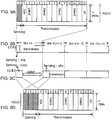
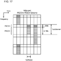
- FIG. 17 illustrates an example of resource allocation of V2X.
- the example in FIG. 17 illustrates resource allocation of a case where a Physical Sidelink Control CHannel (PSCCH), which is a control channel, and a PSSCH, which is a data channel, are allocated adjacent to each other.
- PSCCH Physical Sidelink Control CHannel
- the horizontal axis represents the time axis direction
- the vertical axis represents the frequency axis direction.
- the example illustrated in FIG. 17 includes four subchannels in the frequency axis direction.
- a PSCCH including two Resource Blocks (RBs) and a PSSCH including m (m is an integer of 3 or more) RBs are allocated adjacent to each other in each subchannel.
- RBs Resource Blocks
- m is an integer of 3 or more
- a PSCCH resource represented by the diagonal lines and a PSSCH resource represented by the horizonal lines are used for actual transmission.
- Sidelink Control Information including information such as a modulation method and a coding rate of corresponding PSSCH data is mapped to the PSCCH resource.
- FIG. 18 also illustrates an example of resource allocation of V2X.
- the example in FIG. 18 illustrates resource allocation of a case where a PSCCH and a PSSCH are not allocated adjacent to each other.
- a PSCCH resource represented by the diagonal lines and a PSSCH resource represented by the horizontal lines are used for actual transmission.
- the PSCCH and PSSCH resources are not adjacent to each other. SCI about the corresponding PSSCH is mapped to the PSCCH resource.
- Examples of the resource allocation method for V2X in 4G include a centralized resource allocation method (In-coverage RRC_CONNECTED UEs) and a distributed resource allocation method (In-coverage RRC_IDLE UEs or out-of-coverage UEs).
- the centralized allocation method is applicable when a terminal apparatus that implements V2X is within the coverage of a mobile communication system and is also called mode 3.
- the distributed resource allocation method is applicable even when a terminal apparatus is not within the coverage of a mobile communication system and is also called mode 4.
- mode 4 no communication is performed between the terminal apparatus and the mobile communication system for resource allocation so that a transmission delay that occurs after transmission data is generated by the terminal apparatus is shortened, and a strict delay requirement can be satisfied.
- each terminal apparatus senses the frequency band used for V2X when transmission data is generated, excludes resources that are likely to be used by other terminal apparatuses based on the sensing result, and selects the resource to be used for transmitting the data.
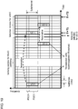
- FIG. 19 illustrates an example of resource selection.
- a terminal apparatus or User Equipment (UE) #3 sets a selection window with a time width of [T+T1, T+T2].
- T1 ⁇ 4, 10 ⁇ T2 ⁇ 100, and specific numerical values of T1 and T2 are determined by the implementation of the terminal.
- UE#3 then excludes resources from the selection window based on control information in the PSCCH in a sensing window having a time width of 1000 ms up to time T and an energy measurement of the corresponding PSSCH.
- the step of excluding resources as described above may be referred to as a resource exclusion step.
- UE#3 sets a threshold higher than the threshold currently set (for example, "3 dB" higher) to relax (or loosen) the exclusion condition.
- UE#3 uses the increased threshold to perform the resource exclusion step again and repeats the resource exclusion step until the candidate resources remaining without being excluded are 20% or more of all the resources in the selection window.
- UE#3 further narrows down the remaining candidate resources to 20% or more of all the resources in ascending order of average receiving power and randomly selects one resource therefrom.
- UE#3 excludes the resources of UE#1 and UE#2 in the selection window. UE#3 then narrows down the candidate resources that are not excluded in the selection window in ascending order of the average receiving power. UE#3 selects any one of 20% or more of all the remaining resources and uses the selected resource to transmit control information and data.
- a wireless terminal that selects a control information resource from a first control information resource pool to transmit priority data and selects a control information resource from a second control information resource pool to transmit non-priority data.
- a wireless communication system that supports D2D communication can avoid or reduce failure in priority data communication.
- a wireless terminal that uses any one of a plurality of resource pools provided for each communication service based on resource map information indicating allocation pattern of the plurality of resource pools.
- Non-Patent Literature 1 As described in the above Non-Patent Literature 1, a very high level of communication delay and reliability is needed for V2X communication in 5G.
- the selection window has a minimum size of 10 ms.
- a delay of 10 ms may be generated by the terminal apparatus between the start of resource selection and the data transmission. With this level of delay of 10 ms, there is a case where the communication delay needed by 5G is not satisfied.
- the terminal apparatus can select a resource.
- the available resources are 20%, 80% of the resources are used by other terminal apparatuses may be included in the set of candidate resources.
- the terminal apparatus selects a candidate resource and transmits a signal to a different terminal apparatus, a signal transmitted from the different terminal apparatus may become an interference source. Packet data may collide due to the occurrence of interference. If the remaining candidate resources are only about 20%, there is a case where the communication reliability needed by 5G is not satisfied.
- control information resource is selected from a different control information resource pool for transmission of priority data and for transmission of non-priority data, provides no solution to the issue on communication delay and reliability.
- the above-mentioned technique in which any one of a plurality of resource pools provided for each communication service is used based on the resource map information, provides no solution to the issue on communication delay and reliability.
- an object of the disclosed technique is to provide a communication apparatus, a base station apparatus, and a communication system capable of reducing communication delay and improving communication reliability.
- a communication apparatus that supports sidelink communication, the communication apparatus includes, a scheduler configured to select one resource pool from a plurality of resource pools based on a selection criterion set for an individual one of the plurality of resource pools and information regarding sidelink communication, and a transmission unit configured to transmit control information and data by using a resource included in the resource pool selected by the scheduler, wherein the information regarding sidelink communication is a QoS (Quality of Service) condition requested when the data is transmitted via sidelink communication.
- QoS Quality of Service
- the 3GPP specifications are updated as needed. Therefore, the latest specifications at the time of filing the present application may be used as the specifications described above. Further, the terms and technical contents described in the latest specifications may appropriately be used in the present description.
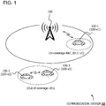
- FIG. 1 illustrates a configuration example of a communication system 10 according to a first embodiment.
- the communication system 10 includes a plurality of terminal apparatuses (or communication devices, which may hereinafter be referred to as "terminals”) 100-2 and 100-3.
- the communication system 10 may include a base station apparatus (which may hereinafter be referred to as a "base station") 200 and a terminal 100-1.
- the terminal 100-1 can receive information about a selection criterion, etc. from the base station 200 and use the received information to perform wireless communication with the other terminals 100-2 and 100-3.
- the terminals 100-2 and 100-3 can receive information about a selection criterion within the coverage range of the base station 200.
- the terminals 100-1 to 100-3 are, for example, communication devices capable of wireless communication, such as wireless communication chipsets, feature phones, smartphones, personal computers, tablet terminals and game devices.
- the terminals 100-1 to 100-3 can perform wireless communication via V2X communication, for example.
- V2X is a general term for V2V, V2P, V2I, or the like.
- the terminal 100-3 which is a communication peer, may be held by a pedestrian, rather than a vehicle, or provided on a road sign.
- the terminals 100-1 to 100-3 are provided on vehicles 100-v1 to 100-v3, respectively.
- the terminals 100-1 to 100-3 can perform wireless communication via V2X communication in mode 4, for example.
- mode 4 is, for example, a method in which the terminals 100-1 to 100-3 can autonomously select resources.
- the terminal 100-1 can perform V2X communication in mode 4 when in a Radio Resource Control (RRC) idle (RRC_IDLE) state and in an RRC connected state within the coverage range of the base station 200.
- RRC Radio Resource Control
- the terminals 100-2 and 100-3 can perform V2X communication in mode 4 outside the coverage range of the base station 200.
- the RRC idle state is, for example, a standby state in which the terminal 100-1 is not RRC-connected to the network side including the base station 200.
- the RRC connected state (RRC_CONNECTED) is, for example, a state in which the terminal 100-2 is connected to the network including the base station 200 so that data can be transmitted and received.
- the number of terminals 100-2 and 100-3 included in the communication system 10 is not limited to two, but may be three or more.
- terminals 100-1 to 100-3 may be hereinafter referred to as the terminal 100.
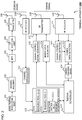
- FIG. 2 illustrates a configuration example of the terminal 100.
- the terminal 100 includes a data traffic processing unit 101, a channel encoder 102, an Inverse Fast Fourier transform (IFFT) 103, a Cyclic Prefix (CP) addition unit 104, a Radio Frequency (RF) transmitter 105, and a transmission antenna 106.
- the terminal 100 includes a reception antenna 110, an RF receiver 111, and a channel demodulator 112.
- the data traffic processing unit 101 generates data to be used in cellular communication, such as voice data and image data.
- the data traffic processing unit 101 outputs the generated data to the channel encoder 102.
- the channel encoder 102 performs error correction encoding processing (which may hereinafter be referred to as "encoding processing") and modulation processing, etc. on the data to covert the data into a transmission signal.
- the channel encoder 102 outputs the converted transmission signal to the IFFT 103.
- the IFFT 103 performs an inverse fast Fourier transform on the transmission signal to covert the transmission signal in the frequency domain into a transmission signal in the time domain.
- the IFFT 103 outputs the transmission signal in the time domain to the CP addition unit 104.
- the CP addition unit 104 adds a cyclic prefix (CP) to the transmission signal in the time domain.
- the CP addition unit 104 outputs the transmission signal, to which the CP is added, to the RF transmitter 105.
- CP cyclic prefix
- the RF transmitter 105 performs Digital-to-Analogue (D/A) conversion processing, frequency conversion processing, etc. on the transmission signal, to which the CP is added, to generate a cellular signal of a radio band.
- the RF transmitter 105 outputs the cellular signal to the transmission antenna 106.
- the transmission antenna 106 transmits the cellular signal to the base station 200.
- the reception antenna 110 receives the cellular signal transmitted from the base station 200 and outputs the received cellular signal to the RF receiver 111.
- the RF receiver 111 performs frequency conversion processing, Analogue-to-Digital (A/D) conversion processing, etc. on the cellular signal to convert the cellular signal of the radio band into a reception signal of the base band.
- the RF receiver 111 outputs the reception signal to the channel demodulator 112.
- the channel demodulator 112 performs demodulation processing, error correction decoding processing (which may hereinafter be referred to as "decoding processing"), etc. on the reception signal to reproduce (or extract) the data, the control information, or the like.
- decoding processing error correction decoding processing
- the channel demodulator 112 stores the reproduced information about the resource pool and information about the selection criterion in a resource information memory 113.
- the information about the resource pool and the information about the selection criterion may collectively be referred to as the resource information.
- the terminal 100 includes the resource information memory 113, a sidelink scheduler (which may hereinafter be referred to as a "scheduler") 114, a signal (PSCCH: Physical Sidelink Control Channel) generator (which may hereinafter be referred to as a “control signal generator”) 115 including Sidelink Control Information (SCI).
- a signal including sidelink control information (SCI) may be referred to as sidelink control signal.
- the terminal 100 includes a sidelink data generator (which may hereinafter be referred to as a "data generator”) 116, an RF transmitter 117, a transmission antenna 118, a reception antenna 120, and an RF receiver 121.
- the terminal 100 includes a sidelink control signal detector (which may hereinafter be referred to as a “control signal detector”) 122, a sidelink data detector (which may hereinafter be referred to as a “data detector”) 123, and an energy measuring device 124.
- a sidelink control signal detector which may hereinafter be referred to as a "control signal detector”
- a sidelink data detector which may hereinafter be referred to as a "data detector”
- an energy measuring device 124 an energy measuring device
- the resource information memory 113 stores resource information (information about the resource pool and information about the selection criterion).
- the information about the resource pool includes information 113-a about the resource pool (k-1) and information 113-b about the resource pool k.
- the information 113-a about the resource pool (k-1) includes information indicating the resource range of the resource pool (k-1), namely, the range of the frequency resources and time resources to be used by the resource pool (k-1), for example.
- the information 113-b about the resource pool k includes information indicating the resource range of the resource pool k, namely, the range of the frequency resources and the time resources to be used by the resource pool k, for example.
- the information about the selection criterion is, for example, information about usage ranking indicating that at least one of the resource pool k and the resource pool (k-1) is preferentially used per Quality of Service (QoS).
- the information about the selection criterion includes, for example, QoS and usage ranking.
- the terminal 100 selects the resource pool k or the resource pool (k-1) in order of the usage ranking based on whether QoS matches the conditions.
- FIG. 6 illustrates an example of a selection criteria table 113-c in which the information about the selection criteria is summarized in a table format.
- FIG. 6 will be described in detail below.
- the selection criteria table 113-c is stored in the resource information memory 113.
- QoS is, for example, QoS requested when data is transmitted via sidelink communication.
- QoS is also parameters related to the data or information about sidelink communication. Details of the QoS will be described below.
- the scheduler 114 performs scheduling related to sidelink communication. Specifically, the scheduler 114 selects the resource pool k or the resource pool (k-1) in accordance with the selection criterion set for each of the resource pool k and resource pool (k-1) and the information about sidelink communication. That is, for example, the scheduler 114 selects at least one resource pool that corresponds to the QoS output from the data generator 116 by using the selection criteria table 113-c (for example, FIG. 6 ). Next, the scheduler 114 performs carrier sense by using a sensing method set for each of the resource pool k and the resource pool (k-1) selected.
- sensing and “carrier sense” may be used without distinction.
- FIG. 5 illustrates an example of resource allocation of the resource pool k and the resource pool (k-1).
- the resource pool k is, for example, a resource pool in which slot-level (or subframe) sensing is performed.
- the scheduler 114 sets a past number ms (for example, 1000 ms) before the resource selection as the sensing window and sets the selection window in the range of 10 ms to 100 ms after the resource selection.
- the scheduler 114 then performs a resource exclusion step and a resource narrowing step on each resource in the selection window on a slot basis (or on a subframe basis) based on each resource in the sensing window.
- the resource exclusion step and the resource narrowing step are performed based on a reception energy measurement for the reception signal received using each resource, as described with reference to FIG. 19 , for example.
- the scheduler 114 performs the resource exclusion step and the resource narrowing step based on the reception energy of each resource output from the energy measuring device 124.
- the scheduler 114 randomly selects any one of the candidate resources narrowed down in the selection window.
- the scheduler 114 also determines a Modulation and Coding Scheme (MCS), the number of repetitions, etc.
- MCS Modulation and Coding Scheme
- the scheduler 114 outputs information about the selected resource, the MCS, the number of repetitions, etc. to the control signal generator 115 and the data generator 116 as control information.
- one subframe is composed of 14 symbols in 4G
- one slot is composed of 14 symbols in 5G.
- one resource unit is one subframe in 4G
- one resource unit is one slot in 5G.
- one resource unit may be described as a slot.
- sensing is performed on a symbol basis. While details will be described below, for example, the scheduler 114 performs sensing at the "0th" symbol as illustrated in FIG. 9A or performs sensing using three symbols from the "0th" to "2nd” symbols as illustrated in FIG. 9D . In this case, the scheduler 114 determines whether the slot including the measured symbol can be used, based on the symbol-based reception energy measurement result output from the energy measuring device 124. For example, when the reception energy measurement result is equal to or greater than a threshold, the scheduler 114 determines "busy" and defers the transmission by its own terminal.
- the scheduler 114 determines "idle” and determines that the slot can be used. When determining that the slot can be used, the scheduler 114 determines the slot as information about the resource. The scheduler 114 also determines the MCS, the number of repetitions, etc. The scheduler 114 outputs these items of information to the control signal generator 115 as control information.
- the control signal generator 115 generates a control signal by performing encoding processing and modulation processing on the control information.
- the control signal generator 115 outputs the generated control signal to the RF transmitter 117.
- the data generator (or data generation unit) 116 generates data to be transmitted by the terminal 100.
- the data generator 116 determines QoS based on the parameters of the generated data. Examples of such parameters include communication delay, communication reliability, and priority of the data.
- the data generator 116 may determine the delay and reliability based on a use case (or a scenario) in which the data is used.
- the use case include a case in which a vehicle equipped with the terminal 100 performs vehicle platooning, automatic driving (advanced driving), extended sensors, remote driving, or the like.
- the data generator 116 may determine the delay and reliability based on whether the vehicle equipped with the terminal 100 performs semi-automatic driving or fully automatic driving.
- the data generator 116 may determine the data priority based on the type of data, for example, whether or not the data is urgent data.
- the data generator 116 determines the delay and reliability based on the use case or the like and determines the priority based on the type of data, for example.
- the data generator 116 uses the delay, the reliability, and all or part of the priority to determine QoS of the data.
- the data generator 116 outputs the determined QoS to the scheduler 114.
- the data generator 116 receives MCS from the scheduler 114, performs encoding processing, modulation processing, etc. on the generated data in accordance with the MCS, and generates a transmission signal.
- the data generator 116 outputs the transmission signal to the RF transmitter 117.
- the RF transmitter 117 performs D/A conversion processing, frequency conversion processing, etc. on the control signal and the transmission signal to convert these signals into a sidelink signal of the radio band.
- the RF transmitter 117 transmits the sidelink signal to another terminal via the transmission antenna 118.
- the RF transmitter 117 transmits the sidelink signal in accordance with the information about the resource included in the control signal. This enables the control signal to be transmitted by using the PSCCH and the data to be transmitted by using the PSSCH.
- the RF transmitter 117 is also a transmission unit that transmits the control signal and the data to another terminal, for example.
- the transmission antenna 118 transmits a sidelink signal to another terminal.
- the reception antenna 120 receives a sidelink signal transmitted from another terminal and outputs the received sidelink signal to the RF receiver 121.
- the RF receiver 121 performs frequency conversion processing, A/D conversion processing, etc. on the sidelink signal to convert the sidelink signal into a reception signal of the base band.
- the RF receiver 121 outputs the reception signal to the control signal detector 122 and the data detector 123.
- the control signal detector 122 extracts the reception signal received by using the PSCCH as a control signal, performs demodulation processing and decoding processing on the extracted control signal, and reproduces (or extracts) the control information.
- the control signal detector 122 outputs the reproduced control information to the data detector 123.
- the data detector 123 senses the reception signal received by using the PSSCH as a data signal based on the control information.
- the data detector 123 outputs the sensed data signal to the energy measuring device 124.
- the data detector 123 may perform demodulation processing, decoding processing, etc. on the sensed data signal to reproduce the data and output the reproduced data to an application processing unit or the like.
- the energy measuring device 124 measures the reception energy of the sensed data signal.
- FIG. 4 illustrates a configuration example of the energy measuring device 124.
- a reception signal y R (t) is converted into a digital signal by an Analogue-to-Digital Converter (ADC) 1211 of the RF receiver 121 and is converted from the signal in the time domain to a signal in the frequency domain by a Fast Fourier Transform (FFT) 1231 of the data detector 123.
- ADC Analogue-to-Digital Converter
- FFT Fast Fourier Transform
- the energy measuring device 124 includes squaring coefficients 1241 and mean value 1242.
- the squaring coefficients 1241 calculates, for example, a square of the reception signal y R (t) in the frequency domain to obtain reception energy of the reception signal y R (t).
- the mean value 1242 calculates an average value E R of the reception energy.
- the energy measuring device 124 outputs the average reception energy E R to the scheduler 114 as a reception energy measurement result. As described above, the scheduler 114 compares the reception energy measurement result with a threshold to determine "busy" or "idle".
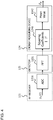
- FIG. 3 illustrates a configuration example of the base station 200.
- the base station 200 includes a radio unit 210, a processor 211, and an Interface (IF).
- IF Interface
- the radio unit 210 includes a transmission unit 201 and a reception unit 202.
- the transmission unit 201 performs encoding processing, modulation processing, frequency conversion processing, etc. on resource information output from a scheduler 203 to convert the resource information into a cellular signal.
- the transmission unit 201 transmits the cellular signal to the terminal 100.
- the reception unit 202 receives the cellular signal transmitted from the terminal 100, performs frequency conversion processing, demodulation processing, decoding processing, etc. on the received cellular signal, and reproduces the information transmitted from the terminal 100.
- the reception unit 202 outputs the reproduced information to the scheduler 203.
- the processor 211 includes the scheduler 203.
- the scheduler 203 performs scheduling of the wireless communication for each terminal 100 within the coverage range of the base station 200.
- the scheduler 203 generates resource information and transmits the generated resource information to the terminal 100-1 via the transmission unit 201.
- the processor 211 may be, for example, a Central Processing Unit (CPU), a Micro Processing Unit (MPU), a Digital Signal Processor (DSP), or a Field Programmable Gate Array (FPGA).
- CPU Central Processing Unit
- MPU Micro Processing Unit
- DSP Digital Signal Processor
- FPGA Field Programmable Gate Array
- the IF 212 includes a backhaul communication unit 204.
- the backhaul communication unit 204 transmits information output from the scheduler 203 to a server device connected via a wired network and other base stations and outputs information received from a server device and other base stations to the scheduler 203.
- a plurality of resource pools k and k-1 are used as illustrated in FIG. 5 .
- the resource pool k or k-1 can be selected based on QoS of data.
- FIG. 6 illustrates an example of the selection criteria table 113-c.
- QoS represents, for example, transmission delay (latency) and communication reliability.
- QoS0 represents QoS that requests a delay of 3 ms or less and reliability of 10 -5 .
- a delay of "3 ms” represents, for example, that an allowable transmission delay is 3 ms or less.
- Reliability of "10 -5 " represents, for example, a degree of reliability such that, when the amount of transmission packet data is "100,000", the terminal on the reception side can receive "99,999" transmission packets.
- QoS1 represents QoS that requests a delay of 10 ms or less and reliability of 10 -4 . That is, an allowable transmission delay is 10 ms or less, and a degree of reliability is such that, when the amount of transmission packet data is "10,000", the terminal on the reception side can receive "9,999" transmission packets.
- the terminal 100 can use the resource pool (k-1) with a higher usage ranking than the resource pool k in accordance with the selection criteria table 113-c. This is because, for example, "QoS0" represents the strictest conditions (low delay and high reliability) in the QoS levels illustrated in FIG. 6 , and the use of the resource pool (k-1) in which symbol-level sensing is performed enables data transmission that satisfies such strict conditions. That is, the terminal 100 can perform communication with low delay and high reliability by using the resource pool (k-1).
- the terminal 100 can use the resource pool k with a higher usage ranking than the resource pool (k-1) in accordance with the selection criteria. This is because, for example, "QoS1" is a QoS level that needs normal delay and reliability, and the use of the resource pool k in which slot-level sensing is performed is sufficient to satisfy such a level of QoS.
- the resource pool k can be used, and even when QoS is "QoS1", the resource pool (k-1) can be used.
- the resource pool (k-1) can be used. For example, if only the resource pool (k-1) is used for all the cases of "QoS0", While the resources of the resource pool (k-1) are used by many terminals 100 for data transmission, the resources of the resource pool k are hardly used. Such a situation may occur. Thus, for example, to prevent deterioration of resource utilization efficiency, another resource pool can be utilized.
- resource pool (k-1) is illustrates as the resource pool in which symbol-level sensing is performed.
- symbol-level sensing may be performed in a plurality of resource pools (k-1), (k-2), and so on.
- any one of the resource pools (k-1), (k-2), ..., in which symbol-level sensing is performed may serve as "Priority 1".
- the resource pools (k-1), (k-2), ..., in which symbol-level sensing is performed may be allocated in accordance with the type of data (whether or not the data is emergency data) to be transmitted or the type of service.
- FIG. 6 illustrates the example with two types of QoS, which are "QoS0" and "QoS1".
- QoS0 the number of types of QoS
- QoS1 the number of types of QoS
- three or more types of QoS such as "QoS3", “"QoS4", ..., may also be used.
- the QoS may be allocated in accordance with the magnitude of the delay and the degree of the reliability.
- the magnitude of the delay and the degree of the reliability of each QoS illustrated in FIG. 6 are also examples.
- the delay may be 2 ms and the reliability may be 10 -5 for "QoS0".
- FIGS. 7 to 11 illustrate usage examples of the resource pools. Specific examples of symbol-level sensing will be described by referring to these usage examples.
- the terminal 100-1 (UE#1) transmits "QoS0" data
- the terminal 100-2 (UE#2) transmits "QoS1" data.
- the delay and reliability of "QoS0" and "QoS1" are assumed to be the same as those illustrated in FIG. 6 .
- the horizontal axis represents time
- the vertical axis represents frequency.
- the terminal 100-2 generates "QoS1" data and performs resource selection at the timing of the second slot from the beginning (S10).
- QoS of the data is "QoS1”
- the terminal 100-2 selects the resource pool k in accordance with the selection criteria table 113-c.
- the terminal 100-2 sets a selection window in the resource pool k and performs the resource exclusion step and the resource narrowing step within the range of the selection window.
- the terminal 100-1 generates "QoS0" data and performs resource selection at the timing of the fourth slot from the beginning (S11). In this case, since QoS of the data is "QoS0", the terminal 100-1 selects the resource pool (k-1) in accordance with the selection criteria table 113-c.
- the terminal 100-1 performs symbol-level sensing in the resource pool (k-1) at the time of the fifth slot (S12).
- FIG. 9A illustrates an example of symbol-level sensing performed by the terminal 100-1.
- FIG. 9A an example of a PSSCH of the resource pool (k-1) is illustrated.
- a PSSCH is allocated to a different frequency band of the same slot.
- FIG. 9A illustrates an example in which the leading "0" symbol is used for sensing.
- the terminal 100-1 performs carrier sense on the leading "0" symbol before data transmission.
- the terminal 100-1 determines that the resource in the resource pool (k-1) that has been sensed is "busy". In this case, the terminal 100-1 postpones (defers) its own data transmission.
- the terminal 100-1 determines "idle” and starts the transmission from the "1" symbol.
- the example illustrated in FIG. 9A includes a symbol in which Automatic Gain Control (AGC) is performed and a symbol used for transmitting a Demodulation Reference Signal (DMRS), and blank symbols other than the above are used for data transmission.
- AGC Automatic Gain Control
- DMRS Demodulation Reference Signal
- the terminal 100-1 uses the "3" symbol, the "4" symbol, the "6” symbol, and the like to transmit the "QoS0" data.
- FIGS. 9C and 9D illustrate examples in which the terminal 100-2 performs sensing on the same frequency band (the resource pool (k-1)) at the same timing as the terminal 100-1.
- the terminal 100-2 performs carrier sense by using the first three symbols, namely, from the "0" to "2" symbols.
- the terminal 100-2 also performs symbol-level sensing when using the resource pool (k-1).
- the terminal 100-2 performs sensing by using three symbols.
- the number of symbols used by the terminal 100-1 for sensing is "1"
- the number of symbols used by the terminal 100-2 for sensing is "3"
- the number of symbols used for sensing varies even for the same resource pool (k-1). This is because QoS of the data transmitted by the terminal 100-1 and QoS of the data transmitted by the terminal 100-2 are different. That is, since the terminal 100-1 transmits the "QoS0" data, low delay and high reliability are needed. Thus, the terminal 100-1 performs sensing by using the first one symbol. In contrast, since the terminal 100-2 transmits the "QoS1" data, normal delay and normal reliability are needed. Thus, the terminal 100-2 uses more symbols than in the case of transmission of the "QoS0" data to perform sensing. That is, in the example of FIG. 9D , the terminal 100-2 uses three symbols to perform sensing.
- the number of symbols (or the number of resources used for sensing on a symbol basis) differs depending on the QoS level.
- the number of symbols used for sensing is equal to or less than a second threshold
- the number of symbols used for sensing is more than the second threshold
- the terminal 100-1 when transmitting "QoS” data, the terminal 100-1 may set no sensing symbol. Further, when transmitting "QoS1" data, the terminal 100-2 may set two symbols (two symbols, which are the "0" symbol and the "1" symbol) as sensing symbols. Any number of symbols may be set to be used for sensing as long as the number of symbols is smaller for "QoS0" than for "QoS1".
- the terminal 100-2 determines "busy” and defers its own transmission for one slot.
- the terminal 100-2 then performs carrier sense on the same frequency band (the frequency band of the resource pool (k-1)) in the (n+1)th slot next and obtains the result that the reception energy of the signal transmitted from another terminal 100-1 is lower than the threshold.
- the terminal 100-2 transmits the "QoS1" data by using the "3rd” symbol from the (n+1)th slot onward.
- the terminal 100-2 performs sensing (S10), and subsequently, the terminal 100-1 performs sensing (S11).
- S11 As a result of performing carrier sense on the resource pool (k-1), the terminal 100-1 obtains the result "idle".
- the terminal 100-1 transmits "QoS0" data by using the resource in the resource pool (k-1) (S12).
- this example will be described.
- the terminal 100-2 repeats the resource exclusion step n (n is an integer of 2 or more) times in the selection window of the resource pool k, and after n times of repetitions, remaining candidate resources are less than 20% of all the resources within the range of the selection window.
- the terminal 100-2 switches the resource pool from the resource pool k to the resource pool (k-1) and performs symbol-level sensing in the resource pool (k-1) (S13).
- the terminal 100-2 senses "idle”, as a result of the carrier sense, and thus transmits "QoS1" data by using the resource in the resource pool (k-1) (S14).
- the terminal 100-2 selects the resource pool k in accordance with the selection criteria table 113-c to transmits "QoS1" data as the next data.
- the terminal 100-2 then performs the resource exclusion step in the selection window of the resource pool k, selects one resource from the remaining candidate resources, and transmits the "QoS1" data (S15).
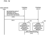
- FIG. 12 illustrates an example of a sequence performed by the base station 200 and the terminals 100-1 and 100-2. It is assumed that the terminals 100-1 and 100-2 are within the coverage range of the base station 200 and in an RRC-connected state with the base station 200.
- the base station 200 transmits resource information to the terminals 100-1 and 100-2 (S20, S21).
- the scheduler 203 or the transmission unit 201 may transmit the resource information to the terminals 100-1 and 100-2 using the RRC protocol.
- the scheduler 203 or the transmission unit 201 may be a transmission unit that transmits the resource information.
- the terminals 100-1 and 100-2 store the received resource information in the resource information memory 113 (S22, S23).
- the resource information is received by the RF receiver 111 of each of the terminals 100-1 and 100-2, reproduced by the channel demodulator 112, and stored in the resource information memory 113 by the channel demodulator 112.
- the RF receiver 111 is also a reception unit that receives the resource information, for example.
- information about the resource pool (k-1) 113-a, information about the resource pool k 113-b, and the selection criteria table 113-c are stored in the resource information memory 113.
- the terminals 100-1 and 100-2 transmit and receive data via V2X communication (S24) while being in the coverage range of the base station 200 and being in an RRC idle state or while being outside the coverage range of the base station 200.
- the base station 200 can determine (or designate) the selection criterion and the resource pool, and the terminal 100 can perform V2X communication by using the selection criterion and resource pool determined by the base station 200.
- FIG. 13 is a flowchart illustrating an operation example of the terminal 100-1.
- the terminal 100-1 may be referred to as the terminal 100.
- the terminal 100 starts processing (S30) and generates data (S31).
- the data generator 116 generates the data.
- the scheduler 114 may select the resource pool k, which has the second highest usage ranking.
- An example of the certain conditions includes a case where many remaining or narrowed resources with good quality are within the range of the selection window of the resource pool k (for example, the remaining resources are X% or more, the energy measured for the narrowed resources is smaller than a threshold, etc.).
- the terminal 100 determines whether no transmission from another terminal is sensed as a result of the sensing (S36). For example, the scheduler 114 makes this determination by obtaining, from the energy measuring device 124, an average reception energy E R of a reception signal y R (t) received using the sensing symbol of the resource pool (k-1) and determining whether the average reception energy E R is smaller than a threshold.
- the terminal 100 transmits the data by using a resource in the resource pool (k-1), which has been sensed (S37). For example, the terminal 100 performs the following processing.
- the scheduler 114 determines that the resource in the resource pool (k-1) is in an "idle" state.
- the scheduler 114 then outputs the resource allocation information illustrated in FIG. 9A to the control signal generator 115.
- the control signal generator 115 generates a control signal including the resource allocation information and outputs the resource allocation information to the RF transmitter 117.
- the RF transmitter 117 transmits the control signal by using the PSCCH of the resource pool (k-1) and the data by using the PSSCH of the resource pool (k-1) to another terminal (for example, the terminal 100-2).
- the terminal 100 ends the series of processes (S38).
- the terminal 100 defers its own transmission (S40). For example, the terminal 100 performs the following processing.
- the scheduler 114 determines that the resource pool (k-1) is in a "busy" state. Consequently, the scheduler 114 outputs no resource allocation information to the control signal generator 115 and controls the data generator 116 to defer the data output to the RF transmitter 117 for a period of one slot.
- the terminal 100 then repeats the processing of S35 onward in the next slot.
- n represents the number of repetitions of the resource exclusion step.
- the terminal 100 sets the selection window and the sensing window in the resource pool k and performs the resource exclusion step and the resource narrowing step (S42).
- the terminal 100 determines whether the candidate resources remain 20% or more of all the resources in the selection window as a result of the resource exclusion step, (S43). If the candidate resources remain 20% or more (Yes in S43), the terminal 100 randomly selects one resource from the candidate resources (S44). Next, the terminal 100 transmits the data by using the selected resource (S37). The terminal 100 then ends the series of processes (S38).
- the terminal 100 determines whether the number of repetitions n is smaller than a limit count N QoS (S45).
- the terminal 100 increases the threshold for the reception energy (or relaxes the conditions) and repeats the resource exclusion step.
- a limit is given to the number of repetitions n, and the terminal 100 determines whether the number of repetitions n has reached the limit count N QoS .
- the scheduler 114 counts the number of repetitions n of the resource exclusion step and determines whether the number of repetitions n counted is less than the limit count N QoS .
- the terminal 100 increments the number of repetitions n (S46), increases the threshold for the reception energy, and performs the resource exclusion step again (S42). For example, when the number of repetitions n is less than the limit count N QoS , the scheduler 114 increments the number of repetitions n, increases the threshold for the reception energy, and performs the resource exclusion step again.
- the terminal 100 repeats the resource exclusion step (a loop of S42, S43, S45, and S46), and when the number of repetitions n reaches the limit count N QoS (No in S45), the terminal 100 switches the resource pool from the resource pool k to the resource pool (k-1) and preforms the processing of S35 onward.
- This process corresponds to, for example, the process of S13 in FIG. 10 .
- the scheduler 114 switches the resource pool from the resource pool k to the resource pool (k-1) and performs symbol-level sensing in the resource pool (k-1).
- the terminal 100 switches the resource pool from the resource pool k to the resource pool (k-1) since, when the number of repetitions n reaches the limit count N QoS , even if the resource exclusion step is further performed, the candidate resources are highly unlikely to be 20% or more.
- the terminal 100 uses the resource pool (k-1) instead. Subsequently, the terminal 100 performs the processing of S35 onward.
- the terminal 100 selects the resource pool k in accordance with the selection criteria table 113-c. The terminal 100 then perform the processing of S41 onward. In this case, too, when the candidate resources are less than 20% (No in S43) and when the number of repetitions n of the resource exclusion step reaches the limit count N QoS (No in S45), the terminal 100 switches to the resource pool (k-1) and performs the resource selection (S35 to S38).
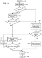
- FIG. 14 is a flowchart illustrating another operation example of the terminal 100.
- the terminal 100 performs the resource exclusion step in the resource pool k (S42), selects the resource in the resource pool k when the available resources are a% or more in the selection window (Yes in S50), selects a resource in the resource pool k (S44), and transmits the data by using the selected resource (S37).
- the resource pool (k-1) is immediately used without repeatedly performing the resource exclusion step. In this way, data transmission that satisfies such a strict QoS can be performed.
- FIG. 15 illustrates another example of the selection criteria table 113-c.
- the selection criteria table 113-c in FIG. 15 illustrates a case where the resource pool k and the resource pool (k-1) have the same usage ranking for "QoS0".
- the scheduler 114 may select the resource pool k or the resource pool (k-1) when the QoS is "QoS0".
- the terminal 100 may select the resource pool k, when the terminal 100 selects the resource pool (k-1), symbol-level sensing is performed.
- the communication delay can be reduced, and the communication reliability can be improved.
- the resource information is transmitted from the base station 200 and received by the terminal 100, and the terminal 100 performs V2X communication by using the received resource information.
- the resource information may be stored in the resource information memory 113 at the time of factory shipment.
- the terminal 100 can perform V2X communication with another terminal by using the resource information stored in the resource information memory 113 without receiving the resource information from the base station 200.
- the selection criterion may be determined by the terminal 100 or by the base station 200 as described above in ⁇ 6.1 Example of Sequence Performed by Base Station Apparatus and Terminal Apparatuses>, for example.
- the selection criterion determined (or designated) by the base station 200 may be used by performing the above ⁇ 6.1 Example of Sequence Performed by Base Station Apparatus and Terminal Apparatuses>, for example.
- the terminal 100 can select any one of the resource pool (k-1), in which symbol-level sensing is performed, and the resource pool k, in which slot-level sensing is performed, based on the QoS and the selection criterion of the data to be transmitted. Since the sensing is performed on a symbol basis in the resource pool (k-1), for example, when the resource pool (k-1) is selected, a communication delay requirement of 3 ms can be achieved. Thus, the terminal 100 according to the first embodiment can reduce the communication delay.
- the terminal 100 can use any one of the resource pools. This allows the resource pools to be allocated to the individual terminals. For example, while one terminal uses the resource pool k, another terminal uses the resource pool (k-1). Thus, according to the first embodiment, compared with the case where only one of the resource pools is used, the probability that only one resource pool is used can be reduced. Therefore, according to the first embodiment, the communication reliability can be improved.
- the resource utilization efficiency may decrease.
- the terminal 100 can use any one of the resource pools, more resources are available, compared with the case where only one of the resource pools is used. Consequently, the resource utilization efficiency can also be improved.
- FIG. 16 illustrates an example of a hardware configuration of the terminal 100.
- the terminal 100 includes a Read Only (ROM) 130, a Random Access Memory (RAM) 131, a processor 132, a memory 133, a radio unit 134, and an antenna 140.
- ROM Read Only
- RAM Random Access Memory
- the processor 132 reads a program stored in the ROM 130, loads the program onto the RAM 131, and executes the loaded program to realize the functions of the data traffic processing unit 101, the channel encoder 102, the IFFT 103, and the CP addition unit 104. In addition, the processor 132 executes the program to realize the functions of the channel demodulator 112, the scheduler 114, the control signal generator 115, the data generator 116, the control signal detector 122, the data detector 123, and the energy measuring device 124.
- the processor 132 corresponds to, for example, the data traffic processing unit 101, the channel encoder 102, the IFFT 103, the CP addition unit 104, the channel demodulator 112, and the scheduler 114 in the first embodiment.
- the processor 132 corresponds to, for example, the control signal generator 115, the data generator 116, the control signal detector 122, the data detector 123 and the energy measuring device 124 in the first embodiment.
- the memory 133 corresponds to, for example, the resource information memory 113 in the first embodiment.
- the radio unit 134 corresponds to, for example, the RF transmitters 105 and 117 and the RF receivers 111 and 121 in the first embodiment.
- the antenna 140 corresponds to, for example, the transmission antennas 106 and 118 and the reception antennas 110 and 120 in the first embodiment.
Landscapes
- Engineering & Computer Science (AREA)
- Computer Networks & Wireless Communication (AREA)
- Signal Processing (AREA)
- Mobile Radio Communication Systems (AREA)
Applications Claiming Priority (1)
| Application Number | Priority Date | Filing Date | Title |
|---|---|---|---|
| PCT/JP2018/034662 WO2020059045A1 (fr) | 2018-09-19 | 2018-09-19 | Dispositif de communication, dispositif de station de base, et système de communication |
Publications (3)
| Publication Number | Publication Date |
|---|---|
| EP3855820A1 true EP3855820A1 (fr) | 2021-07-28 |
| EP3855820A4 EP3855820A4 (fr) | 2021-09-08 |
| EP3855820B1 EP3855820B1 (fr) | 2023-08-02 |
Family
ID=69886986
Family Applications (1)
| Application Number | Title | Priority Date | Filing Date |
|---|---|---|---|
| EP18934068.0A Active EP3855820B1 (fr) | 2018-09-19 | 2018-09-19 | Dispositif de communication, dispositif de station de base, et système de communication |
Country Status (5)
| Country | Link |
|---|---|
| US (2) | US12245218B2 (fr) |
| EP (1) | EP3855820B1 (fr) |
| JP (1) | JP7116341B2 (fr) |
| CN (1) | CN112740781B (fr) |
| WO (1) | WO2020059045A1 (fr) |
Families Citing this family (6)
| Publication number | Priority date | Publication date | Assignee | Title |
|---|---|---|---|---|
| CN113455077B (zh) * | 2018-10-31 | 2024-06-18 | 皇家飞利浦有限公司 | 无线通信系统及其操作方法 |
| CN116567828A (zh) * | 2019-02-14 | 2023-08-08 | 北京小米移动软件有限公司 | 资源确定方法及装置 |
| CN115226230A (zh) * | 2019-07-15 | 2022-10-21 | 上海朗帛通信技术有限公司 | 一种被用于无线通信的节点中的方法和装置 |
| CN112584343B (zh) * | 2019-09-30 | 2022-05-10 | 华为技术有限公司 | 通信方法及相关产品 |
| US12335947B2 (en) * | 2020-10-23 | 2025-06-17 | Qualcomm Incorporated | Resource allocation techniques for sidelink transmissions, and dynamic selection between resource allocation techniques based on sidelink communication reliability |
| US12185279B2 (en) | 2020-10-23 | 2024-12-31 | Qualcomm Incorporated | Receiver assisted sidelink resource allocation using an adaptive threshold |
Family Cites Families (26)
| Publication number | Priority date | Publication date | Assignee | Title |
|---|---|---|---|---|
| WO2015022029A1 (fr) * | 2013-08-15 | 2015-02-19 | Telefonaktiebolaget L M Ericsson (Publ) | Définition d'un modèle de ressource adapté pour un nœud d'accès |
| JP2017515431A (ja) * | 2014-03-19 | 2017-06-08 | インターデイジタル パテント ホールディングス インコーポレイテッド | デバイスツーデバイス同期 |
| WO2015194916A1 (fr) | 2014-06-20 | 2015-12-23 | 엘지전자 주식회사 | Procédé de détermination de ressources pour la communication de dispositif à dispositif (d2d) dans un système de communication sans fil et appareil associé |
| JP2016096475A (ja) * | 2014-11-14 | 2016-05-26 | Kddi株式会社 | 無線制御装置、端末装置、および通信方法 |
| CN107852727B (zh) * | 2015-04-09 | 2022-01-18 | 夏普株式会社 | 对覆盖范围外无线终端进行侧链路直接发现资源池分配的方法及装置 |
| US10390357B2 (en) * | 2015-07-13 | 2019-08-20 | Lg Electronics Inc. | Method and apparatus for transmitting or receiving data in wireless communication system |
| WO2017026409A1 (fr) * | 2015-08-11 | 2017-02-16 | 京セラ株式会社 | Terminal sans fil |
| CN106688300B (zh) * | 2015-08-21 | 2021-05-18 | 华为技术有限公司 | 无线通信的方法、网络设备、用户设备和系统 |
| JP6726679B2 (ja) | 2015-11-05 | 2020-07-22 | 富士通株式会社 | 通信装置および無線通信方法 |
| WO2017122949A1 (fr) * | 2016-01-14 | 2017-07-20 | 엘지전자 주식회사 | Procédé pour mesurer et rapporter une ressource de dispositif à dispositif (d2d) dans un système de communication sans fil, et appareil associé |
| WO2017145867A1 (fr) | 2016-02-23 | 2017-08-31 | 京セラ株式会社 | Terminal sans fil |
| WO2017150956A1 (fr) * | 2016-03-04 | 2017-09-08 | 엘지전자 주식회사 | Procédé de sélection de ressource de transmission v2x implémenté par un terminal dans un système de communication sans fil, et terminal l'utilisant |
| WO2017163545A1 (fr) * | 2016-03-23 | 2017-09-28 | 日本電気株式会社 | Dispositif et procédé destinés à commander une communication de dispositif à dispositif |
| WO2017171514A1 (fr) * | 2016-04-01 | 2017-10-05 | 엘지전자 주식회사 | Procédé de gestion de connexion d'ue pour l'émission et la réception d'un message v2x dans un système de communication sans fil, et appareil associé |
| US10757550B2 (en) * | 2016-04-07 | 2020-08-25 | Lg Electronics Inc. | Method for performing sensing during terminal-specific sensing period in wireless communication system, and terminal using same |
| WO2017188803A2 (fr) * | 2016-04-29 | 2017-11-02 | Lg Electronics Inc. | Procédé et appareil pour configurer une structure de trame pour une nouvelle technologie d'accès radio dans un système de communication sans fil |
| JP2019149593A (ja) * | 2016-07-15 | 2019-09-05 | シャープ株式会社 | 端末装置および方法 |
| WO2018027528A1 (fr) * | 2016-08-09 | 2018-02-15 | Panasonic Intellectual Property Corporation Of America | Sélection et détection améliorées de ressources radio destinées aux transmissions v2x |
| WO2018031086A1 (fr) * | 2016-08-12 | 2018-02-15 | Intel Corporation | Procédés de sélection de ressource autonome d'ue dans des communications de véhicule à véhicule avec détermination de valeur seuil de puissance |
| EP3506707B1 (fr) * | 2016-09-21 | 2022-04-27 | Guangdong Oppo Mobile Telecommunications Corp., Ltd. | Procédé et appareil d'émission de signal |
| WO2018081979A1 (fr) * | 2016-11-03 | 2018-05-11 | Panasonic Intellectual Property Corporation Of America | Procédé, appareil et système de communication sans fil |
| US11190976B2 (en) * | 2017-07-03 | 2021-11-30 | Ntt Docomo, Inc. | User apparatus and transmission method |
| EP3672338B1 (fr) * | 2017-09-29 | 2022-11-30 | LG Electronics Inc. | Procédé de transmission d'un message v2x effectué par un terminal dans un système de communication sans fil, et terminal mettant en oeuvre ce procédé |
| JP7213884B2 (ja) * | 2018-02-05 | 2023-01-27 | オッポ広東移動通信有限公司 | リソース予約方法及び装置、並びにコンピュータ記憶媒体 |
| US20200029340A1 (en) * | 2018-07-19 | 2020-01-23 | Samsung Electronics Co., Ltd. | Method and apparatus for nr v2x resource selection |
| WO2020033422A1 (fr) * | 2018-08-07 | 2020-02-13 | Idac Holdings, Inc. | Procédés et appareils pour sélection de ressource autonome dans une communication véhicule-à-tout nouvelle radio (nrv2x) |
-
2018
- 2018-09-19 WO PCT/JP2018/034662 patent/WO2020059045A1/fr not_active Ceased
- 2018-09-19 CN CN201880097765.8A patent/CN112740781B/zh active Active
- 2018-09-19 EP EP18934068.0A patent/EP3855820B1/fr active Active
- 2018-09-19 JP JP2020547517A patent/JP7116341B2/ja active Active
-
2021
- 2021-03-17 US US17/204,337 patent/US12245218B2/en active Active
-
2025
- 2025-01-24 US US19/036,161 patent/US20250184995A1/en active Pending
Also Published As
| Publication number | Publication date |
|---|---|
| US20250184995A1 (en) | 2025-06-05 |
| CN112740781B (zh) | 2024-08-13 |
| US12245218B2 (en) | 2025-03-04 |
| EP3855820B1 (fr) | 2023-08-02 |
| CN112740781A (zh) | 2021-04-30 |
| JP7116341B2 (ja) | 2022-08-10 |
| US20210298044A1 (en) | 2021-09-23 |
| WO2020059045A1 (fr) | 2020-03-26 |
| JPWO2020059045A1 (ja) | 2021-08-30 |
| EP3855820A4 (fr) | 2021-09-08 |
Similar Documents
| Publication | Publication Date | Title |
|---|---|---|
| US12245218B2 (en) | Communication apparatus, base station apparatus, and communication system | |
| US12470943B2 (en) | Radio communication device and radio communication method | |
| KR102919671B1 (ko) | 단말 및 송신 방법 | |
| US20160255647A1 (en) | Device-to-device data channel signaling | |
| CN108632968A (zh) | 用于上行功率控制的方法和装置 | |
| KR102263629B1 (ko) | 단말 장치, 기지국 장치, 무선 통신 시스템 및 무선 통신 방법 | |
| CN112469127B (zh) | 一种通信方法、终端及网络设备 | |
| JP2019503626A (ja) | 通信方法、ネットワーク側装置、及び端末 | |
| JPWO2020166179A1 (ja) | 端末装置、通信方法及び集積回路 | |
| CN108702699B (zh) | 无线局域网中的接入点、站点和其中用于接入点选择的方法 | |
| JP6390789B2 (ja) | 基地局、端末、無線通信システム、基地局の制御方法および端末の制御方法 | |
| CN119032290A (zh) | 侧链路定位 | |
| EP3158673B1 (fr) | Procédés et appareils pour la transmission répétée de blocs radio | |
| CN114175777A (zh) | 通信方法、设备及其计算机可读介质 | |
| JP7807504B2 (ja) | 情報伝送方法、通信装置、コンピュータ可読記憶媒体およびチップ | |
| CN111587603A (zh) | 网络节点、无线通信设备及其中用于接入免许可无线电频带的方法 | |
| US20220386282A1 (en) | Communications device, infrastructure equipment and methods | |
| CN111108769A (zh) | 基站装置、终端装置、无线通信系统及发送时机设定方法 | |
| CN116406523A (zh) | 功率控制方法和装置 | |
| EP4462701A1 (fr) | Procédé d'apprentissage de faisceau et appareil de communication | |
| US20250151029A1 (en) | Methods and apparatuses of resource selection for sidelink communication | |
| CN107294692A (zh) | 一种数据包的传输方法、装置及基站 | |
| CN121794940A (en) | Reporting delay differences between transmitting and receiving points | |
| CN121666723A (zh) | 侧链路定位参考信号 | |
| WO2018142549A1 (fr) | Dispositif de station de base, équipement terminal et procédé de transmission |
Legal Events
| Date | Code | Title | Description |
|---|---|---|---|
| STAA | Information on the status of an ep patent application or granted ep patent |
Free format text: STATUS: THE INTERNATIONAL PUBLICATION HAS BEEN MADE |
|
| PUAI | Public reference made under article 153(3) epc to a published international application that has entered the european phase |
Free format text: ORIGINAL CODE: 0009012 |
|
| STAA | Information on the status of an ep patent application or granted ep patent |
Free format text: STATUS: REQUEST FOR EXAMINATION WAS MADE |
|
| 17P | Request for examination filed |
Effective date: 20210317 |
|
| AK | Designated contracting states |
Kind code of ref document: A1 Designated state(s): AL AT BE BG CH CY CZ DE DK EE ES FI FR GB GR HR HU IE IS IT LI LT LU LV MC MK MT NL NO PL PT RO RS SE SI SK SM TR |
|
| A4 | Supplementary search report drawn up and despatched |
Effective date: 20210811 |
|
| RIC1 | Information provided on ipc code assigned before grant |
Ipc: H04W 92/18 20090101ALI20210805BHEP Ipc: H04W 72/08 20090101ALI20210805BHEP Ipc: H04W 72/02 20090101AFI20210805BHEP |
|
| DAV | Request for validation of the european patent (deleted) | ||
| DAX | Request for extension of the european patent (deleted) | ||
| GRAP | Despatch of communication of intention to grant a patent |
Free format text: ORIGINAL CODE: EPIDOSNIGR1 |
|
| STAA | Information on the status of an ep patent application or granted ep patent |
Free format text: STATUS: GRANT OF PATENT IS INTENDED |
|
| RIC1 | Information provided on ipc code assigned before grant |
Ipc: H04W 92/18 20090101ALI20230208BHEP Ipc: H04W 72/02 20090101AFI20230208BHEP |
|
| INTG | Intention to grant announced |
Effective date: 20230303 |
|
| GRAS | Grant fee paid |
Free format text: ORIGINAL CODE: EPIDOSNIGR3 |
|
| GRAA | (expected) grant |
Free format text: ORIGINAL CODE: 0009210 |
|
| STAA | Information on the status of an ep patent application or granted ep patent |
Free format text: STATUS: THE PATENT HAS BEEN GRANTED |
|
| AK | Designated contracting states |
Kind code of ref document: B1 Designated state(s): AL AT BE BG CH CY CZ DE DK EE ES FI FR GB GR HR HU IE IS IT LI LT LU LV MC MK MT NL NO PL PT RO RS SE SI SK SM TR |
|
| REG | Reference to a national code |
Ref country code: GB Ref legal event code: FG4D |
|
| REG | Reference to a national code |
Ref country code: CH Ref legal event code: EP |
|
| REG | Reference to a national code |
Ref country code: DE Ref legal event code: R096 Ref document number: 602018054841 Country of ref document: DE |
|
| REG | Reference to a national code |
Ref country code: IE Ref legal event code: FG4D |
|
| REG | Reference to a national code |
Ref country code: LT Ref legal event code: MG9D |
|
| REG | Reference to a national code |
Ref country code: NL Ref legal event code: MP Effective date: 20230802 |
|
| REG | Reference to a national code |
Ref country code: AT Ref legal event code: MK05 Ref document number: 1596262 Country of ref document: AT Kind code of ref document: T Effective date: 20230802 |
|
| PG25 | Lapsed in a contracting state [announced via postgrant information from national office to epo] |
Ref country code: GR Free format text: LAPSE BECAUSE OF FAILURE TO SUBMIT A TRANSLATION OF THE DESCRIPTION OR TO PAY THE FEE WITHIN THE PRESCRIBED TIME-LIMIT Effective date: 20231103 |
|
| PG25 | Lapsed in a contracting state [announced via postgrant information from national office to epo] |
Ref country code: IS Free format text: LAPSE BECAUSE OF FAILURE TO SUBMIT A TRANSLATION OF THE DESCRIPTION OR TO PAY THE FEE WITHIN THE PRESCRIBED TIME-LIMIT Effective date: 20231202 |
|
| PG25 | Lapsed in a contracting state [announced via postgrant information from national office to epo] |
Ref country code: SE Free format text: LAPSE BECAUSE OF FAILURE TO SUBMIT A TRANSLATION OF THE DESCRIPTION OR TO PAY THE FEE WITHIN THE PRESCRIBED TIME-LIMIT Effective date: 20230802 Ref country code: RS Free format text: LAPSE BECAUSE OF FAILURE TO SUBMIT A TRANSLATION OF THE DESCRIPTION OR TO PAY THE FEE WITHIN THE PRESCRIBED TIME-LIMIT Effective date: 20230802 Ref country code: PT Free format text: LAPSE BECAUSE OF FAILURE TO SUBMIT A TRANSLATION OF THE DESCRIPTION OR TO PAY THE FEE WITHIN THE PRESCRIBED TIME-LIMIT Effective date: 20231204 Ref country code: NO Free format text: LAPSE BECAUSE OF FAILURE TO SUBMIT A TRANSLATION OF THE DESCRIPTION OR TO PAY THE FEE WITHIN THE PRESCRIBED TIME-LIMIT Effective date: 20231102 Ref country code: NL Free format text: LAPSE BECAUSE OF FAILURE TO SUBMIT A TRANSLATION OF THE DESCRIPTION OR TO PAY THE FEE WITHIN THE PRESCRIBED TIME-LIMIT Effective date: 20230802 Ref country code: LV Free format text: LAPSE BECAUSE OF FAILURE TO SUBMIT A TRANSLATION OF THE DESCRIPTION OR TO PAY THE FEE WITHIN THE PRESCRIBED TIME-LIMIT Effective date: 20230802 Ref country code: LT Free format text: LAPSE BECAUSE OF FAILURE TO SUBMIT A TRANSLATION OF THE DESCRIPTION OR TO PAY THE FEE WITHIN THE PRESCRIBED TIME-LIMIT Effective date: 20230802 Ref country code: IS Free format text: LAPSE BECAUSE OF FAILURE TO SUBMIT A TRANSLATION OF THE DESCRIPTION OR TO PAY THE FEE WITHIN THE PRESCRIBED TIME-LIMIT Effective date: 20231202 Ref country code: HR Free format text: LAPSE BECAUSE OF FAILURE TO SUBMIT A TRANSLATION OF THE DESCRIPTION OR TO PAY THE FEE WITHIN THE PRESCRIBED TIME-LIMIT Effective date: 20230802 Ref country code: GR Free format text: LAPSE BECAUSE OF FAILURE TO SUBMIT A TRANSLATION OF THE DESCRIPTION OR TO PAY THE FEE WITHIN THE PRESCRIBED TIME-LIMIT Effective date: 20231103 Ref country code: FI Free format text: LAPSE BECAUSE OF FAILURE TO SUBMIT A TRANSLATION OF THE DESCRIPTION OR TO PAY THE FEE WITHIN THE PRESCRIBED TIME-LIMIT Effective date: 20230802 Ref country code: AT Free format text: LAPSE BECAUSE OF FAILURE TO SUBMIT A TRANSLATION OF THE DESCRIPTION OR TO PAY THE FEE WITHIN THE PRESCRIBED TIME-LIMIT Effective date: 20230802 |
|
| PG25 | Lapsed in a contracting state [announced via postgrant information from national office to epo] |
Ref country code: PL Free format text: LAPSE BECAUSE OF FAILURE TO SUBMIT A TRANSLATION OF THE DESCRIPTION OR TO PAY THE FEE WITHIN THE PRESCRIBED TIME-LIMIT Effective date: 20230802 |
|
| PG25 | Lapsed in a contracting state [announced via postgrant information from national office to epo] |
Ref country code: ES Free format text: LAPSE BECAUSE OF FAILURE TO SUBMIT A TRANSLATION OF THE DESCRIPTION OR TO PAY THE FEE WITHIN THE PRESCRIBED TIME-LIMIT Effective date: 20230802 |
|
| PG25 | Lapsed in a contracting state [announced via postgrant information from national office to epo] |
Ref country code: SM Free format text: LAPSE BECAUSE OF FAILURE TO SUBMIT A TRANSLATION OF THE DESCRIPTION OR TO PAY THE FEE WITHIN THE PRESCRIBED TIME-LIMIT Effective date: 20230802 Ref country code: RO Free format text: LAPSE BECAUSE OF FAILURE TO SUBMIT A TRANSLATION OF THE DESCRIPTION OR TO PAY THE FEE WITHIN THE PRESCRIBED TIME-LIMIT Effective date: 20230802 Ref country code: ES Free format text: LAPSE BECAUSE OF FAILURE TO SUBMIT A TRANSLATION OF THE DESCRIPTION OR TO PAY THE FEE WITHIN THE PRESCRIBED TIME-LIMIT Effective date: 20230802 Ref country code: EE Free format text: LAPSE BECAUSE OF FAILURE TO SUBMIT A TRANSLATION OF THE DESCRIPTION OR TO PAY THE FEE WITHIN THE PRESCRIBED TIME-LIMIT Effective date: 20230802 Ref country code: DK Free format text: LAPSE BECAUSE OF FAILURE TO SUBMIT A TRANSLATION OF THE DESCRIPTION OR TO PAY THE FEE WITHIN THE PRESCRIBED TIME-LIMIT Effective date: 20230802 Ref country code: CZ Free format text: LAPSE BECAUSE OF FAILURE TO SUBMIT A TRANSLATION OF THE DESCRIPTION OR TO PAY THE FEE WITHIN THE PRESCRIBED TIME-LIMIT Effective date: 20230802 Ref country code: SK Free format text: LAPSE BECAUSE OF FAILURE TO SUBMIT A TRANSLATION OF THE DESCRIPTION OR TO PAY THE FEE WITHIN THE PRESCRIBED TIME-LIMIT Effective date: 20230802 |
|
| REG | Reference to a national code |
Ref country code: CH Ref legal event code: PL |
|
| REG | Reference to a national code |
Ref country code: DE Ref legal event code: R097 Ref document number: 602018054841 Country of ref document: DE |
|
| PG25 | Lapsed in a contracting state [announced via postgrant information from national office to epo] |
Ref country code: LU Free format text: LAPSE BECAUSE OF NON-PAYMENT OF DUE FEES Effective date: 20230919 |
|
| REG | Reference to a national code |
Ref country code: BE Ref legal event code: MM Effective date: 20230930 |
|
| PG25 | Lapsed in a contracting state [announced via postgrant information from national office to epo] |
Ref country code: LU Free format text: LAPSE BECAUSE OF NON-PAYMENT OF DUE FEES Effective date: 20230919 Ref country code: IT Free format text: LAPSE BECAUSE OF FAILURE TO SUBMIT A TRANSLATION OF THE DESCRIPTION OR TO PAY THE FEE WITHIN THE PRESCRIBED TIME-LIMIT Effective date: 20230802 Ref country code: MC Free format text: LAPSE BECAUSE OF FAILURE TO SUBMIT A TRANSLATION OF THE DESCRIPTION OR TO PAY THE FEE WITHIN THE PRESCRIBED TIME-LIMIT Effective date: 20230802 |
|
| PLBE | No opposition filed within time limit |
Free format text: ORIGINAL CODE: 0009261 |
|
| STAA | Information on the status of an ep patent application or granted ep patent |
Free format text: STATUS: NO OPPOSITION FILED WITHIN TIME LIMIT |
|
| REG | Reference to a national code |
Ref country code: IE Ref legal event code: MM4A |
|
| PG25 | Lapsed in a contracting state [announced via postgrant information from national office to epo] |
Ref country code: IE Free format text: LAPSE BECAUSE OF NON-PAYMENT OF DUE FEES Effective date: 20230919 |
|
| 26N | No opposition filed |
Effective date: 20240503 |
|
| PG25 | Lapsed in a contracting state [announced via postgrant information from national office to epo] |
Ref country code: CH Free format text: LAPSE BECAUSE OF NON-PAYMENT OF DUE FEES Effective date: 20230930 |
|
| PG25 | Lapsed in a contracting state [announced via postgrant information from national office to epo] |
Ref country code: IE Free format text: LAPSE BECAUSE OF NON-PAYMENT OF DUE FEES Effective date: 20230919 Ref country code: CH Free format text: LAPSE BECAUSE OF NON-PAYMENT OF DUE FEES Effective date: 20230930 Ref country code: SI Free format text: LAPSE BECAUSE OF FAILURE TO SUBMIT A TRANSLATION OF THE DESCRIPTION OR TO PAY THE FEE WITHIN THE PRESCRIBED TIME-LIMIT Effective date: 20230802 |
|
| PG25 | Lapsed in a contracting state [announced via postgrant information from national office to epo] |
Ref country code: BE Free format text: LAPSE BECAUSE OF NON-PAYMENT OF DUE FEES Effective date: 20230930 |
|
| PG25 | Lapsed in a contracting state [announced via postgrant information from national office to epo] |
Ref country code: BG Free format text: LAPSE BECAUSE OF FAILURE TO SUBMIT A TRANSLATION OF THE DESCRIPTION OR TO PAY THE FEE WITHIN THE PRESCRIBED TIME-LIMIT Effective date: 20230802 |
|
| PG25 | Lapsed in a contracting state [announced via postgrant information from national office to epo] |
Ref country code: BG Free format text: LAPSE BECAUSE OF FAILURE TO SUBMIT A TRANSLATION OF THE DESCRIPTION OR TO PAY THE FEE WITHIN THE PRESCRIBED TIME-LIMIT Effective date: 20230802 |
|
| PG25 | Lapsed in a contracting state [announced via postgrant information from national office to epo] |
Ref country code: CY Free format text: LAPSE BECAUSE OF FAILURE TO SUBMIT A TRANSLATION OF THE DESCRIPTION OR TO PAY THE FEE WITHIN THE PRESCRIBED TIME-LIMIT; INVALID AB INITIO Effective date: 20180919 |
|
| PG25 | Lapsed in a contracting state [announced via postgrant information from national office to epo] |
Ref country code: HU Free format text: LAPSE BECAUSE OF FAILURE TO SUBMIT A TRANSLATION OF THE DESCRIPTION OR TO PAY THE FEE WITHIN THE PRESCRIBED TIME-LIMIT; INVALID AB INITIO Effective date: 20180919 |
|
| PGFP | Annual fee paid to national office [announced via postgrant information from national office to epo] |
Ref country code: DE Payment date: 20250820 Year of fee payment: 8 |
|
| PGFP | Annual fee paid to national office [announced via postgrant information from national office to epo] |
Ref country code: GB Payment date: 20250820 Year of fee payment: 8 |
|
| PGFP | Annual fee paid to national office [announced via postgrant information from national office to epo] |
Ref country code: FR Payment date: 20250820 Year of fee payment: 8 |
|
| REG | Reference to a national code |
Ref country code: DE Ref legal event code: R081 Ref document number: 602018054841 Country of ref document: DE Owner name: 1FINITY INC., KAWASAKI-SHI, JP Free format text: FORMER OWNER: FUJITSU LIMITED, KAWASAKI-SHI, KANAGAWA, JP |
|
| PG25 | Lapsed in a contracting state [announced via postgrant information from national office to epo] |
Ref country code: TR Free format text: LAPSE BECAUSE OF FAILURE TO SUBMIT A TRANSLATION OF THE DESCRIPTION OR TO PAY THE FEE WITHIN THE PRESCRIBED TIME-LIMIT Effective date: 20230802 |
|
| REG | Reference to a national code |
Ref country code: GB Ref legal event code: 732E Free format text: REGISTERED BETWEEN 20251127 AND 20251203 |