EP3855837A1 - Kommunikationsverfahren und -vorrichtung - Google Patents
Kommunikationsverfahren und -vorrichtung Download PDFInfo
- Publication number
- EP3855837A1 EP3855837A1 EP19878306.0A EP19878306A EP3855837A1 EP 3855837 A1 EP3855837 A1 EP 3855837A1 EP 19878306 A EP19878306 A EP 19878306A EP 3855837 A1 EP3855837 A1 EP 3855837A1
- Authority
- EP
- European Patent Office
- Prior art keywords
- bwp
- terminal device
- frequency domain
- information
- network device
- Prior art date
- Legal status (The legal status is an assumption and is not a legal conclusion. Google has not performed a legal analysis and makes no representation as to the accuracy of the status listed.)
- Granted
Links
Images


Classifications
-
- H—ELECTRICITY
- H04—ELECTRIC COMMUNICATION TECHNIQUE
- H04L—TRANSMISSION OF DIGITAL INFORMATION, e.g. TELEGRAPHIC COMMUNICATION
- H04L5/00—Arrangements affording multiple use of the transmission path
- H04L5/003—Arrangements for allocating sub-channels of the transmission path
- H04L5/0037—Inter-user or inter-terminal allocation
-
- H—ELECTRICITY
- H04—ELECTRIC COMMUNICATION TECHNIQUE
- H04L—TRANSMISSION OF DIGITAL INFORMATION, e.g. TELEGRAPHIC COMMUNICATION
- H04L5/00—Arrangements affording multiple use of the transmission path
- H04L5/0001—Arrangements for dividing the transmission path
- H04L5/0003—Two-dimensional division
- H04L5/0005—Time-frequency
-
- H—ELECTRICITY
- H04—ELECTRIC COMMUNICATION TECHNIQUE
- H04L—TRANSMISSION OF DIGITAL INFORMATION, e.g. TELEGRAPHIC COMMUNICATION
- H04L5/00—Arrangements affording multiple use of the transmission path
- H04L5/0091—Signalling for the administration of the divided path, e.g. signalling of configuration information
- H04L5/0092—Indication of how the channel is divided
-
- H—ELECTRICITY
- H04—ELECTRIC COMMUNICATION TECHNIQUE
- H04L—TRANSMISSION OF DIGITAL INFORMATION, e.g. TELEGRAPHIC COMMUNICATION
- H04L5/00—Arrangements affording multiple use of the transmission path
- H04L5/0091—Signalling for the administration of the divided path, e.g. signalling of configuration information
- H04L5/0096—Indication of changes in allocation
- H04L5/0098—Signalling of the activation or deactivation of component carriers, subcarriers or frequency bands
-
- H—ELECTRICITY
- H04—ELECTRIC COMMUNICATION TECHNIQUE
- H04W—WIRELESS COMMUNICATION NETWORKS
- H04W4/00—Services specially adapted for wireless communication networks; Facilities therefor
- H04W4/70—Services for machine-to-machine communication [M2M] or machine type communication [MTC]
-
- H—ELECTRICITY
- H04—ELECTRIC COMMUNICATION TECHNIQUE
- H04W—WIRELESS COMMUNICATION NETWORKS
- H04W72/00—Local resource management
- H04W72/04—Wireless resource allocation
- H04W72/044—Wireless resource allocation based on the type of the allocated resource
- H04W72/0453—Resources in frequency domain, e.g. a carrier in FDMA
-
- H—ELECTRICITY
- H04—ELECTRIC COMMUNICATION TECHNIQUE
- H04W—WIRELESS COMMUNICATION NETWORKS
- H04W72/00—Local resource management
- H04W72/20—Control channels or signalling for resource management
- H04W72/21—Control channels or signalling for resource management in the uplink direction of a wireless link, i.e. towards the network
-
- H—ELECTRICITY
- H04—ELECTRIC COMMUNICATION TECHNIQUE
- H04W—WIRELESS COMMUNICATION NETWORKS
- H04W72/00—Local resource management
- H04W72/50—Allocation or scheduling criteria for wireless resources
- H04W72/51—Allocation or scheduling criteria for wireless resources based on terminal or device properties
-
- H—ELECTRICITY
- H04—ELECTRIC COMMUNICATION TECHNIQUE
- H04W—WIRELESS COMMUNICATION NETWORKS
- H04W72/00—Local resource management
- H04W72/50—Allocation or scheduling criteria for wireless resources
- H04W72/56—Allocation or scheduling criteria for wireless resources based on priority criteria
-
- H—ELECTRICITY
- H04—ELECTRIC COMMUNICATION TECHNIQUE
- H04L—TRANSMISSION OF DIGITAL INFORMATION, e.g. TELEGRAPHIC COMMUNICATION
- H04L5/00—Arrangements affording multiple use of the transmission path
- H04L5/0001—Arrangements for dividing the transmission path
- H04L5/0003—Two-dimensional division
- H04L5/0005—Time-frequency
- H04L5/0007—Time-frequency the frequencies being orthogonal, e.g. OFDM(A) or DMT
- H04L5/001—Time-frequency the frequencies being orthogonal, e.g. OFDM(A) or DMT the frequencies being arranged in component carriers
-
- H—ELECTRICITY
- H04—ELECTRIC COMMUNICATION TECHNIQUE
- H04W—WIRELESS COMMUNICATION NETWORKS
- H04W72/00—Local resource management
- H04W72/20—Control channels or signalling for resource management
- H04W72/23—Control channels or signalling for resource management in the downlink direction of a wireless link, i.e. towards a terminal
Definitions
- This application relates to the field of communications technologies, and in particular, to a communications method and apparatus.
- a terminal device and a base station perform wireless communication based on a radio communications technology.
- An uplink (uplink, UL) carrier is used to support uplink communication between the terminal device and the base station
- a downlink (downlink, DL) carrier is used to support downlink communication between the terminal device and the base station.
- a conventional base station-centric service provisioning mode cannot meet service requirements of a large quantity of users in different environments, a device-to-device (for example, vehicle-to-vehicle (vehicle-to-vehicle), vehicle-to-infrastructure (vehicle-to-infrastructure), and vehicle-to-user (vehicle-to-pedestrians)) communications technology emerges, and a sidelink (sidelink, SL) carrier is used to support device-to-device communication.
- SL sidelink
- this application provides a communications method and apparatus, to provide a BWP configuration idea and method, so that a first terminal device can communicate on a first BWP and a second BWP at the same time.
- an embodiment of this application provides a communication method.
- the method includes:
- a first terminal device receives first information sent by a network device, where the first information is used to configure a BWP set; the BWP set includes a first BWP and a second BWP; and the first BWP is used for communication between the first terminal device and the network device, and the second BWP is used for communication between the first terminal device and a second terminal device; and further the first terminal device communicates on at least one first BWP and/or at least one second BWP in the BWP set.
- the network device configures the BWP set for the terminal device, that is, establishes an association relationship (or a correspondence) between the first BWP and the second BWP, so that the first terminal device can communicate on the first BWP and the second BWP that are associated with each other.
- the foregoing manner provides a BWP configuration idea and method, so that the first terminal device can communicate on the first BWP and the second BWP at the same time.
- the first BWP is used for uplink communication between the first terminal device and the network device
- the second BWP is used for uplink communication between the first terminal device and the second terminal device.
- the BWP set further includes a third BWP, and the third BWP is used for downlink communication between the first terminal device and the network device.
- the method further includes: The first terminal device sends second information to the network device, where the second information includes a radio frequency bandwidth supported by the first terminal device.
- An offset value between a first frequency domain position and a second frequency domain position in frequency domain is less than or equal to the radio frequency bandwidth supported by the first terminal device.
- the first frequency domain position is a highest frequency domain position of the first BWP in the BWP set in frequency domain or a highest frequency domain position of the second BWP in the BWP set in frequency domain.
- the second frequency domain position is a lowest frequency domain position of the first BWP in the BWP set in frequency domain or a lowest frequency domain position of the second BWP in the BWP set in frequency domain.
- the first terminal device reports the radio frequency bandwidth supported by the first terminal device to the network device, so that the network device can configure the BWP set based on the radio frequency bandwidth supported by the first terminal device. Because the first BWP and the second BWP in the BWP set meet the foregoing content, it can be ensured that the first terminal device sends data on a UL BWP and an SL BWP in the BWP set at the same time.
- the method further includes: The first terminal device sends third information to the network device, where the third information is used to indicate whether the first terminal device supports communication on the first BWP and the second BWP at the same time.
- the method further includes: The first terminal device receives fourth information, where the fourth information is used to indicate to activate the at least one first BWP or the at least one second BWP; and the first terminal device activates the at least one first BWP and the at least one second BWP based on the fourth information.
- frame structure parameters of the at least one first BWP and the at least one second BWP are different. That the first terminal device communicates on at least one first BWP or at least one second BWP in the first BWP set includes: The first terminal device chooses, based on priorities of the frame structure parameters of the at least one first BWP and the at least one second BWP, to communicate on the at least one first BWP or the at least one second BWP.
- an embodiment of this application provides a communication method.
- the method includes:
- a network device sends first information to a first terminal device, where the first information is used to configure a BWP set; the BWP set includes a first BWP and a second BWP; and the first BWP is used for communication between the first terminal device and the network device, and the second BWP is used for communication between the first terminal device and a second terminal device.
- the network device configures the first BWP and the second BWP into one BWP set, that is, establishes an association relationship (or a correspondence) between the first BWP and the second BWP, so that the first terminal device can communicate on the first BWP and the second BWP that are associated with each other.
- the foregoing manner provides a BWP configuration idea and method, so that the first terminal device can communicate on the first BWP and the second BWP at the same time.
- the first BWP is used for uplink communication between the first terminal device and the network device
- the second BWP is used for uplink communication between the first terminal device and the second terminal device.
- the BWP set further includes a third BWP, and the third BWP is used for downlink communication between the first terminal device and the network device.
- the method further includes: The network device receives second information sent by the first terminal device, where the second information includes a radio frequency bandwidth supported by the first terminal device.
- That a network device sends first information to a first terminal device includes: The network device sends the first information to the first terminal device based on the radio frequency bandwidth supported by the first terminal device.
- An offset value between a first frequency domain position and a second frequency domain position in frequency domain is less than or equal to the radio frequency bandwidth supported by the first terminal device.
- the first frequency domain position is a highest frequency domain position of the first BWP in the BWP set in frequency domain or a highest frequency domain position of the second BWP in the BWP set in frequency domain.
- the second frequency domain position is a lowest frequency domain position of the first BWP in the BWP set in frequency domain or a lowest frequency domain position of the second BWP in the BWP set in frequency domain.
- the method further includes: The network device receives third information sent by the first terminal device, where the third information is used to indicate whether the first terminal device supports communication on the first BWP and the second BWP at the same time. That a network device sends first information to a first terminal device includes: The network device sends the first information to the first terminal device based on the third information if determining that the first terminal device supports communication on the first BWP and the second BWP at the same time.
- the method further includes: The network device sends fourth information to the first terminal device, where the fourth information is used to indicate to activate the at least one first BWP or the at least one second BWP.
- an embodiment of this application provides an apparatus.
- the apparatus may be a network device or a terminal device, or may be a semiconductor chip disposed in a network device or a terminal device.
- the apparatus has a function of implementing various possible implementations of the first aspect and the second aspect.
- the function may be implemented by hardware, or may be implemented by hardware executing corresponding software.
- the hardware or software includes one or more units or modules corresponding to the foregoing function.
- an embodiment of this application provides an apparatus, including a processor and a memory.
- the memory is configured to store computer-executable instructions.
- the processor executes the computer-executable instructions stored in the memory, to enable the apparatus to perform the method performed by the terminal device according to any one of the first aspect or the possible implementations of the first aspect, or to enable the apparatus to perform the method performed by the network device according to any one of the second aspect or the possible implementations of the second aspect.
- an embodiment of this application further provides a communications system.
- the communications system includes the terminal device in any design of the first aspect and the network device in any design of the second aspect.
- an embodiment of this application further provides a computer-readable storage medium
- the computer-readable storage medium stores instructions. When the instructions are run on a computer, the computer is enabled to perform the methods according to the foregoing aspects.
- an embodiment of this application further provides a computer program product including instructions.
- the computer program product runs on a computer, the computer is enabled to perform the methods according to the foregoing aspects.
- the network device may be a device that communicates with a terminal device, for example, may be a base station or a base station controller.
- the network device may provide communication coverage for a particular geographical area, and may communicate with a terminal device located in the coverage area (a cell).
- the network device may be a base transceiver station (base transceiver station, BTS) in a global system for mobile communications (global system for mobile communications, GSM) system or code division multiple access (code division multiple access, CDMA) system, or may be a NodeB (NodeB, NB) in a wideband code division multiple access (wideband code division multiple access, WCDMA) system, or may be an evolved NodeB (evolved NodeB, eNB or eNodeB) in an LTE system, or may be a radio controller in a cloud radio access network (cloud radio access network, CRAN) scenario, or the network device may be a relay station, an access point, a vehicle-mounted device, a wearable device, or a network device in a future 5G network, for example, a gNodeB (gNodeB or gNB) or a transmission reception point (transmission receiving point/transmission reception point, TRP) in new radio (new radio, NR), or the network device may be
- Terminal device is a device having a wireless transceiver function, and may be deployed on land, where the deployment includes indoor or outdoor, handheld, or wearable or vehicle-mounted deployment; may be deployed on water (for example, on a ship); or may be deployed in air (for example, on an airplane, a balloon, and a satellite).
- the terminal device may be a mobile phone (mobile phone), a tablet (Pad), a computer having a wireless transceiver function, a virtual reality (virtual reality, VR) terminal device, an augmented reality (augmented reality, AR) terminal device, a wireless terminal in industrial control (industrial control), a wireless terminal in self driving (self driving), a wireless terminal in telemedicine (remote medical), a wireless terminal in a smart grid (smart grid), a wireless terminal in transportation safety (transportation safety), a wireless terminal in a smart city (smart city), a wireless terminal in a smart home (smart home), or the like.
- An application scenario is not limited in the embodiments of this application.
- the terminal device may sometimes be referred to as user equipment (user equipment, UE), an access terminal device, a UE unit, a UE station, a mobile station, a mobile console, a remote station, a remote terminal device, a mobile device, a UE terminal device, a terminal device, a wireless communications device, a UE agent, a UE apparatus, or the like.
- UE user equipment
- a BWP may be configured for the terminal device in a bandwidth supported by a carrier (which may be referred to as a carrier bandwidth, and whose specific value may be 10 MHz, 15 MHz, 20 MHz, 50 MHz, 100 MHz, 400 MHz, or the like).
- a plurality of BWPs may be configured on one carrier, for example, four BWPs can be configured on one carrier.
- the BWP may also be sometimes referred to as a carrier bandwidth part (carrier bandwidth part), a subband (subband) bandwidth, a narrowband (narrowband) bandwidth, or another name.
- carrier bandwidth part carrier bandwidth part
- subband subband
- narrowband narrowband
- K K > 0 subcarrier
- one BWP is a frequency domain resource on which N non-overlapping RBs are located, and a subcarrier spacing of the RBs may be 15 kHz, 30 kHz, 60 kHz, 120 kHz, 240 kHz, 480 kHz, or another value.
- one BWP is a frequency domain resource on which M non-overlapping resource block groups (resource block group, RBG) are located.
- RBG includes P (P > 0) consecutive RBs, and a subcarrier spacing (subcarrier spacing, SCS) of the RBs maybe 15 kHz, 30 kHz, 60 kHz, 120 kHz, 240 kHz.
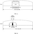
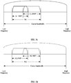
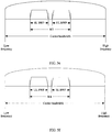
- FIG. 1a to FIG. 1c show three BWP configurations in a carrier bandwidth according to an embodiment of this application.
- FIG. 1a shows a case in which one BWP is configured in the carrier bandwidth.
- a network device may first allocate a BWP within a bandwidth capability range of a terminal to the terminal device, and certainly, may further allocate some or all resources in the BWP to the terminal device for communication.
- the network device can configure different BWPs for the terminal device based on actual scenarios. For example, to reduce power consumption of the terminal device, the network device may allocate a BWP to the terminal device based on a service volume of the terminal device.
- a relatively small BWP such as a BWP 1 shown in FIG. 1b
- a relatively large BWP such as a BWP 2 shown in FIG. 1b
- the network device may allocate a corresponding BWP to the terminal device based on different service types of the terminal device. As shown in FIG.
- one BWP may correspond to one service type.
- a frame structure parameter (numerology) that can meet the service requirement may be configured for the BWP.
- FIG. 1b different BWPs may occupy partially overlapping frequency domain resources.
- FIG. 1c different BWPs may also occupy completely different frequency domain resources and use different numerologies.
- numerologies corresponding to different BWPs may be the same or may be different. This is not limited in this application. It may be understood that in FIG. 1a to FIG. 1c , an example in which one or two BWPs are configured in one carrier is used for description.
- the frame structure parameter is a parameter used in a communications system.
- the frame structure parameter may be a series of physical layer parameters in an air interface.
- One BWP may correspond to one numerology.
- An NR system may support a plurality of numerologies, and the plurality of numerologies may be used at the same time.
- the numerology may include one or more of the following parameter information: a subcarrier spacing, information about a cyclic prefix (cyclic prefix, CP), information about a time unit, a bandwidth, and the like.
- the information about the CP may include a CP length and/or a CP type.
- the CP may be a normal CP (normal CP, NCP) or an extended CP (extended CP, ECP).
- the time unit is used to indicate a time unit in time domain, and may be, for example, a sampling point, a symbol, a mini-slot (mini-slot), a slot (slot), a subframe (subframe), or a radio frame.
- the information about the time unit may include a type, a length, a structure, or the like of the time unit.
- the numerology may include a subcarrier spacing and a CP.
- Table 1 shows numerologies that can be currently supported in the NR system and that is defined by the subcarrier spacing and the CP.
- a network device may allocate a BWP with a subcarrier spacing of 15 kHz and a BWP with a subcarrier spacing of 30 kHz to the terminal.
- the terminal can switch to different BWPs for signal transmission based on different scenarios and service requirements.
- numerologies corresponding to different BWPs may be the same or may be different.
- the subcarrier spacing may be an integer greater than or equal to 0.
- the subcarrier spacing may be 15 kHz, 30 kHz, 60 kHz, 120 kHz, 240 kHz, 480 kHz, or the like.
- a subcarrier spacing is a value of a spacing between central positions or peak positions of two adjacent subcarriers in frequency domain in an orthogonal frequency division multiplexing (orthogonal frequency division multiplexing, OFDM) system.
- a subcarrier spacing in an LTE system is 15 kHz
- a subcarrier spacing in an NR system may be 15 kHz, 30 kHz, 60 kHz, 120 kHz, or the like.
- Radio frequency bandwidth and quantity of radio frequencies A terminal device is used as an example. The terminal device may perform transmission on a radio frequency signal (that is, send or receive a radio frequency signal) through a radio frequency module.
- the radio frequency module may include one or more of an antenna switch module, a filter, an amplifier, a mixer, or a module such as an analog-to-digital conversion module/digital-to-analog conversion module.
- the radio frequency bandwidth may be understood as a maximum transmission bandwidth of a radio frequency signal, and the radio frequency bandwidth may include a transmit bandwidth and/or a receive bandwidth.
- a radio frequency capability of the terminal device may include a radio frequency bandwidth supported by the terminal device.
- the radio frequency bandwidth supported by the terminal device may be understood as a maximum transmission bandwidth that is of a radio frequency signal, that is supported by the terminal device, and that is used to indicate the radio frequency capability of the terminal device.
- the radio frequency bandwidth supported by the terminal device may include a transmit bandwidth supported by the terminal device and/or a receive bandwidth supported by the terminal device.
- a transmit bandwidth of a radio frequency signal is less than or equal to the transmit bandwidth supported by the terminal device, the terminal device can normally send the radio frequency signal.
- a transmit bandwidth of a radio frequency signal is greater than the transmit bandwidth supported by the terminal device, the terminal device may fail to normally send the radio frequency signal. For example, if the terminal device sends a radio frequency signal on a BWP, the terminal device can normally send the radio frequency signal when the transmit bandwidth supported by the terminal device is greater than or equal to a bandwidth of the BWP; otherwise, the terminal device may fail to normally send the radio frequency signal.
- the terminal device can normally send the radio frequency signals when the transmit bandwidth supported by the terminal device is greater than or equal to a sum of bandwidths of the two BWPs and a bandwidth of a frequency band between the two BWPs; otherwise, the terminal device may fail to normally send the radio frequency signals.
- the terminal device can normally receive the radio frequency signal.
- the terminal device may fail to normally receive the radio frequency signal.
- the terminal device can normally receive the radio frequency signal when the receive bandwidth supported by the terminal device is greater than or equal to a bandwidth of the BWP; otherwise, the terminal device may fail to normally receive the radio frequency signal.
- the terminal device receives radio frequency signals on two BWPs (for example, the two BWPs do not overlap in frequency domain) at the same time, the terminal device can normally receive the radio frequency signals when the receive bandwidth supported by the terminal device is greater than or equal to a sum of bandwidths of the two BWPs and a bandwidth of a frequency band between the two BWPs; otherwise, the terminal device may fail to normally receive the radio frequency signals.
- the radio frequency capability of the terminal device may further include a quantity of radio frequencies (including a quantity of transmit radio frequencies and a quantity of receive radio frequencies) supported by the terminal device.
- the quantity of transmit radio frequencies is used as an example. If the quantity of transmit radio frequencies supported by the terminal device is two, it indicates that the terminal device supports two transmit bandwidths, and each transmit radio frequency corresponds to one transmit bandwidth.
- the quantity of radio frequencies supported by the terminal device is related to a quantity of radio frequency modules disposed in the terminal device. For example, if one radio frequency module is disposed in the terminal device, the quantity of radio frequencies supported by the terminal device is one. If two radio frequency modules are disposed in the terminal device, the quantity of radio frequencies supported by the terminal device is two. This is not specifically limited.
- the radio frequency capability of the terminal device may include at least one of the following: the radio frequency bandwidth supported by the terminal device, the quantity of radio frequencies supported by the terminal device, and whether the terminal device supports communication on the first BWP and the second BWP (which are specifically described below) at the same time.
- the radio frequency capability of the terminal device may further include other content. This is not specifically limited. (5) Numberals such as “first" and “second” in the embodiments of this application are merely used for differentiation for ease of description, and are not used to limit a scope of the embodiments of this application or represent a sequence.
- the term "and/or" describes an association relationship for describing associated objects and represents that three relationships may exist.
- a and/or B may represent the following three cases: Only A exists, both A and B exist, and only B exists.
- At least one means one or more.
- At least two means two or more.
- At least one means any combination of these items, including a singular item (piece) or any combination of plural items (pieces).
- at least one (pieces or types) of a, b, or c may indicate: a, b, c, a and b, a and c, b and c, or a, b, and c, where a, b, and c may be singular or plural.
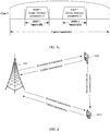
- FIG. 2 is a schematic diagram of a possible architecture of a communications system to which an embodiment of this application is applicable.
- the communications system shown in FIG. 2 includes a network device (for example, a network device 101) and a terminal device (for example, a first terminal device 1021 and a second terminal device 1022).
- FIG. 2 is merely a schematic diagram of an architecture of the communications system.
- a quantity of network devices and a quantity of terminal devices in the communications system are not limited in this embodiment of this application.
- the communications system to which this embodiment of this application is applicable may further include another device such as a core network device, a wireless relay device, and a wireless backhaul device. This is not limited in this embodiment of this application either.
- the network device in this embodiment of this application may integrate all functions into one independent physical device, or may distribute the functions on a plurality of independent physical devices. This is not limited in this embodiment of this application either.
- the terminal device in this embodiment of this application may be connected to the network device in a wireless manner.
- a communications system to which the foregoing system architecture is applicable includes but is not limited to: time division duplex-long term evolution (Time Division Duplexing-Long Term Evolution, TDD LTE), frequency division duplex-long term evolution (Frequency Division Duplexing-Long Term Evolution, FDD LTE), long term evolution-advanced (Long Term Evolution-Advanced, LTE-A), and various future evolved wireless communications systems (for example, a 5G NR communications system).
- the network device 101 may perform data transmission with the first terminal device 1021 and the second terminal device 1022 on an air interface resource.
- the air interface resource may include a time domain resource, a frequency domain resource, and a code domain resource.
- the network device may allocate, by using control information, resources of a data channel, for example, a physical downlink shared channel (physical downlink shared channel, PDSCH) or a physical uplink shared channel (physical uplink shared channel, PUSCH), to the terminal.
- the control information may indicate a symbol and/or an RB to which the data channel is mapped.
- the network device and the terminal device perform data transmission on the allocated time-frequency resources by using the data channel.
- the data transmission may include downlink data transmission and/or uplink data transmission.
- the downlink data (for example, data carried on the PDSCH) transmission may be that the network device sends data to the terminal device
- the uplink data (for example, data carried on the PUSCH) transmission may be that the terminal device sends data to the network device.
- the data may be data in a broad sense, for example, may be user data, or may be system information, broadcast information, or other information.
- the first terminal device 1021 and the second terminal device 1022 may perform data transmission on a sidelink resource. Similar to the air interface resource, the sidelink resource may also include a time domain resource, a frequency domain resource, and a code domain resource.
- a physical channel used by the first terminal device and the second terminal device to perform data transmission may include a physical sidelink shared channel (physical sidelink shared channel, PSSCH) and/or a physical sidelink control channel (physical sidelink control channel, PSCCH).
- PSSCH physical sidelink shared channel
- PSCCH physical sidelink control channel
- the PSSCH is used to transmit data
- the PSCCH is used to transmit control information, for example, scheduling assignment (scheduling assignment, SA) information.
- the uplink transmission is used as an example.
- a data channel used by the network device and the terminal device to perform uplink data transmission may be carried on a UL carrier (for ease of description, the UL carrier is referred to as a first UL carrier for short).
- a data channel used by the first terminal device and the second terminal device to perform data transmission may be carried on an SL carrier.
- the SL carrier may be a UL carrier (for ease of description, the UL carrier is referred to as a second UL carrier for short).
- the first UL carrier and the second UL carrier may be a same carrier, or may be different carriers.
- the network device needs to configure a UL BWP and an SL BWP for the terminal device (for example, the first terminal device) on the UL carrier, where the UL BWP is used by the first terminal device and the network device to perform uplink communication, the SL BWP is used by the first terminal device and the second terminal device to perform communication (for example, the first terminal device sends data to the second terminal device).
- the first terminal device may send data to the second terminal device and receive data sent by the second terminal device on a same SL BWP.
- the SL BWP is used by the first terminal device to send and receive data.
- a BWP used by the first terminal device to send information to the second terminal device may be referred to as an SL transmit BWP (or another name, which is not limited)
- a BWP used by the first terminal device to receive data sent by the second terminal device may be referred to as an SL receive BWP (or another name, which is not limited).
- the SL transmit BWP is used by the first terminal device to send data (for example, the BWP cannot be used by the first terminal device to receive data), and the SL receive BWP is used by the first terminal device to receive data (for example, the BWP cannot be used by the first terminal device to send data).
- the SL transmit BWP and the SL receive BWP may be collectively referred to as an SL BWP.
- the SL BWP may be specifically the SL transmit BWP.
- the SL BWP may be specifically that the SL receive BWP.
- the network device may independently configure a UL BWP and an SL BWP on the UL carrier. For example, the network device configures a UL BWP 0, a UL BWP 1, an SL BWP 0, an SL BWP 1, and an SL BWP 2 for the first terminal device on the UL carrier. Because each UL BWP and each SL BWP exist independently, activation and switching of a UL BWP and an SL BWP are highly random. In this case, the first terminal device may not be able to send data on an activated UL BWP and an activated SL BWP at the same time due to a capability limitation of the first terminal device.
- the embodiments of this application provide a communication method.
- the method includes: A network device determines first information and sends the first information to a first terminal device, where the first information is used to configure a BWP set; the BWP set includes a first BWP and a second BWP; and the first BWP is a BWP used for communication between the first terminal device and the network device, and the second BWP is a BWP used for communication between the first terminal device and a second terminal device; and correspondingly the first terminal device receives the first information and sends data on at least one first BWP and/or at least one second BWP in the BWP set.
- the network device configures the first BWP and the second BWP into one BWP set, that is, establishes an association relationship (or a correspondence) between the first BWP and the second BWP, so that the first terminal device can communicate on the first BWP and the second BWP that are associated with each other.
- the foregoing manner provides a BWP configuration idea and method, so that the first terminal device can communicate on the first BWP and the second BWP at the same time.
- the first BWP may be specifically a UL BWP
- the second BWP may be specifically an SL BWP (or an SL transmit BWP).
- the first BWP may be specifically a DL BWP
- the second BWP may be specifically an SL BWP (or an SL receive BWP).
- the first BWP may include a UL BWP and a DL BWP
- the second BWP may include an SL BWP (or an SL transmit BWP and an SL receive BWP).
- a case in which a first terminal device supports data sending on a first BWP and a second BWP (the first BWP is a UL BWP, and the second BWP is an SL BWP) at the same time is mainly described in detail.
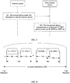
- FIG. 3 is a schematic flowchart corresponding to a communication method according to Embodiment 1 of this application. As shown in FIG. 3 , the method includes the following steps.
- Step 301 A network device sends first information to the first terminal device, where the first information is used to configure a BWP set, and the BWP set includes the UL BWP and the SL BWP.
- a channel for information transmission between the network device and the first terminal device and a channel for information transmission between the first terminal device and a second terminal device may be carried on a same UL carrier.
- the network device may configure one or more UL BWPs and one or more SL BWPs for the first terminal device on the UL carrier. Further, the network device may configure the one or more UL BWPs and the one or more SL BWPs into one or more BWP sets.
- a BWP set may include a UL BWP and an SL BWP.
- the network device allocates a UL BWP 0, a UL BWP 1, a UL BWP 2, a UL BWP 3, an SL BWP 0, an SL BWP 1, an SL BWP 2 and an SL BWP 3 to the first terminal device on the UL carrier.
- Table 2 describes the example 1 of BWP sets configured by the network device.
- Table 2 Example of BWP sets configured by the network device BWP set ULBWP SL BWP Description BWP set 0 UL BWP 0 SL BWP 0 One-to-one BWP set 1 UL BWP 1 SL BWP 1 and SL BWP 2 One-to-many BWP set UL BWP SL BWP Description BWP set 2 UL BWP 2 and UL BWP 3 SL BWP 3 Many-to-one
- the BWP set 0 includes the UL BWP 0 and the SL BWP 0; the BWP set 1 includes the UL BWP 1, the SL BWP 1, and the SL BWP 2; and the BWP set 2 includes the UL BWP 2, the UL BWP 3, and the SL BWP 3.
- a quantity relationship between the UL BWP and the SL BWP included in the BWP set may be one-to-one, one-to-many, many-to-one, or many-to-many. This is not specifically limited.
- a BWP set may include a UL BWP, a DL BWP, and an SL BWP.
- the network device may allocate a UL BWP 0, a UL BWP 1, a UL BWP 2, a UL BWP 3, an SL BWP 0, an SL BWP 1, an SL BWP 2, and an SL BWP 3 to the first terminal device on the UL carrier.
- the network device may allocate a DL BWP 0, a DL BWP 1, a DL BWP 2, and a DL BWP 3 to the first terminal device on a DL carrier.
- Table 3 describes the example 2 of BWP sets configured by the network device.
- Example of BWP sets configured by the network device BWP set ULBWP SL BWP DLBWP BWP set 0 UL BWP 0 SL BWP 0 DL BWP 0 BWP set 1 UL BWP 1 SL BWP 1 and SL BWP 2 DL BWP 1 BWP set 2 UL BWP 2 and UL BWP 3 SL BWP 3 DL BWP 2 and DL BWP 3
- the network device determines to configure the BWP set.
- the first terminal device may not be able to send data on the UL BWP and the SL BWP at the same time due to a radio frequency capability limitation of the first terminal device.
- a quantity of transmit radio frequencies supported by the first terminal device is one, and a transmit bandwidth supported by the first terminal device is 10M.
- the network device activates both the UL BWP 0 and the SL BWP 2, and an offset value between highest frequency domain positions of the UL BWP 0 and the SL BWP 2 and lowest frequency domain positions of the UL BWP 0 and the SL BWP 2 in frequency domain is 15M (greater than 10M).
- the first terminal device cannot send data on the UL BWP 0 and the SL BWP 2 at the same time.
- the network device activates both the UL BWP 0 and the SL BWP 0, and an offset value between highest frequency domain positions of the UL BWP 0 and the SL BWP 0 and lowest frequency domain positions of the UL BWP 0 and the SL BWP 0 in frequency domain is 9M (less than 10M).
- the first terminal device can send data on the UL BWP 0 and the SL BWP 0 at the same time.
- the first terminal device cannot send data on the UL BWP 0 and the SL BWP 2 at the same time.
- the network device activates both the UL BWP 0 and the SL BWP 0, and the first terminal device sends data on the UL BWP 0 and the SL BWP 0 at the same time.
- the first terminal device cannot send data on the UL BWP 1 and the SL BWP 0 at the same time.
- the network device may configure the BWP set based on a radio frequency capability of the first terminal device.
- the network device configures the UL BWP and the SL BWP into one BWP set based on the radio frequency capability of the first terminal device, that is, establishes an association relationship between the UL BWP and the SL BWP, so that the first terminal device can communicate normally on the UL BWP and the SL BWP that are associated with each other.
- the network device may configure the BWP set based on the transmit bandwidth supported by the first terminal device.
- the network device may allocate the UL BWP and the SL BWP to the first terminal device and configure the BWP set on the UL carrier based on the transmit bandwidth supported by the first terminal device and according to a predefined pairing rule of the UL BWP and the SL BWP in the BWP set. For example, on the UL carrier, the network device allocates one or more UL BWPs and one or more SL BWPs to the first terminal device based on the transmit bandwidth supported by the first terminal device, and configures, according to a numbering rule, the BWP set by setting numbers for the one or more UL BWPs and the one or more SL BWPs.
- the network device allocates two UL BWPs and two SL BWPs to the first terminal device on the UL carrier based on the transmit bandwidth supported by the first terminal device, configures a number of one UL BWP as UL BWP 0 and a number of the other UL BWP as UL BWP 1, and configures a number of one SL BWP as SL BWP 0 and a number of the other SL BWP as SL BWP 1.
- a UL BWP and an SL BWP with a same number form a BWP set.
- the UL BWP 0 and the SL BWP 0 form a BWP set
- the UL BWP 1 and the SL BWP 1 form a BWP set.
- the first information may include numbers of the UL BWPs and the SL BWPs.
- the first terminal device may determine, based on the numbers of the UL BWPs and the SL BWPs, that the UL BWP and the SL BWP with the same number form a BWP set.
- the BWP set includes one UL BWP and one SL BWP (in this case, the numbering rule is one-to-one) is used for description.
- the numbering rule may alternatively be one-to-many, many-to-one, or many-to-many. This is not specifically limited.
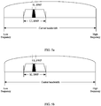
- the network device may configure the BWP set based on the transmit bandwidth supported by the first terminal device and bandwidths of the allocated UL BWP and SL BWP. For example, referring to an example in FIG.
- the network device configures a UL BWP 0 (4M), a UL BWP 1 (5M), an SL BWP 0 (4M), and an SL BWP 1 (5M), and further configures, based on the transmit bandwidth (for example, 10M) supported by the first terminal device, the UL BWP 0 and the SL BWP 0 to form a BWP set (for example, a BWP set 0), and the UL BWP 1 and the SL BWP 1 to form a BWP set (for example, a BWP set 1).
- the transmit bandwidth for example, 10M
- the first information may include an identifier of the BWP set 0, identifiers of the UL BWP 0 and the SL BWP 0 that correspond to the identifier of the BWP set 0, an identifier of the BWP set 1, and identifiers of the UL BWP 1 and the SL BWP 1 that correspond to the identifier of the BWP set 1.
- the first terminal device may obtain the UL BWP and the SL BWP included in each BWP set.
- the identifier of the BWP set may be information for identifying the BWP set, and the identifier of the UL BWP or the SL BWP may be a number of the UL BWP or the SL BWP. This is not specifically limited.
- the network device may configure, on the UL carrier based on the transmit bandwidth supported by the first terminal device, a BWP set and BWP information of a UL BWP and an SL BWP that are included in the BWP set. For example, referring to the example in FIG. 4 , the network device determines a BWP set 0 on the UL carrier based on the transmit bandwidth (for example, 10 M) supported by the first terminal device, and configures the UL BWP 0 and the SL BWP 0 in the BWP set. In this case, the UL BWP 0 and the SL BWP 0 form the BWP set 0.
- the first information may include an identifier of the BWP set 0, and identifiers of the UL BWP 0 and the SL BWP 0 that correspond to the identifier of the BWP set 0.
- the first terminal device may obtain the UL BWP and the SL BWP that are included in the BWP set. It may be understood that one BWP set is used as an example above, and the network device may alternatively configure a plurality of BWP sets on the UL carrier based on the transmit bandwidth supported by the first terminal device.
- the network device configures the BWP and indicates the BWP to the first terminal device.
- the network device may also configure the BWP and indicate the BWP to the first terminal device in another manner. This is not specifically limited in this embodiment of this application.
- each BWP set configured by the network device may meet the following condition: An offset value between a first frequency domain position and a second frequency domain position in frequency domain is less than or equal to a radio frequency bandwidth (for example, the transmit bandwidth) supported by the first terminal device.
- the first frequency domain position is a highest frequency domain position of the first BWP in the BWP set in frequency domain or a highest frequency domain position of the second BWP in the BWP set in frequency domain.
- the second frequency domain position is a lowest frequency domain position of the first BWP in the BWP set in frequency domain or a lowest frequency domain position of the second BWP in the BWP set in frequency domain.
- the UL BWP and the SL BWP in the BWP set configured by the network device meet at least one of the following:
- the UL BWPs in (1) and (2) each may be any UL BWP in the BWP set
- the SL BWPs in (1) and (2) each may be any SL BWP in the BWP set. That the UL BWP and the SL BWP in the BWP set configured by the network device meet at least one of (1) and (2) may be understood as that each combination (including one UL BWP and one SL BWP) formed from one or more UL BWPs and one or more SL BWPs in the BWP set meets at least one of (1) and (2).
- the radio frequency bandwidth supported by the first terminal device is 10M
- the network device allocates the UL BWP 0 (bandwidth: 4M), the UL BWP 1 (bandwidth: 5M), the SL BWP 0 (bandwidth: 4M), and the SL BWP 1 (bandwidth: 5M) to the first terminal device on the UL carrier.
- the network device may configure the UL BWP 0 and the SL BWP 0 into one BWP set (for example, the BWP set 0).
- an offset value between highest frequency domain positions of the UL BWP 1 and the SL BWP 1 and lowest frequency domain positions of the UL BWP 1 and the SL BWP 1 in frequency domain is 8M (less than 10M)
- the network device may configure the UL BWP 1 and the SL BWP 1 into one BWP set (for example, the BWP set 1).
- an offset value between highest frequency domain positions of the UL BWP 1 and the SL BWP 0 and lowest frequency domain positions of the UL BWP 1 and the SL BWP 0 in frequency domain is 11M (greater than 10M).
- the UL BWP 1 and the SL BWP 0 are not suitable to be configured into one BWP set. It may be understood that, when the network device configures the BWP set, there may be a plurality of possible configuration results. This is not limited in this embodiment of this application.
- the UL BWP and the SL BWP in the BWP set configured by the network device meet at least one of the following:
- the UL BWPs in (1) to (4) each may refer to all UL BWPs in the BWP set (that is, all the UL BWPs are considered as a whole), and the SL BWPs in (1) to (4) each may refer to all SL BWPs in the BWP set (that is, all the SL BWPs are considered as a whole).
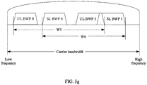
- the BWP set includes a UL BWP 0, a UL BWP 1, an SL BWP 0, and an SL BWP 1.
- the offset value between the highest frequency domain position and the lowest frequency domain position that are of the UL BWP in frequency domain in (1) is W5 in FIG.
- FIG. 5g shows an example, of that described in (3), in which the UL BWP and the SL BWP completely overlap.
- FIG. 5g is an example, of that described in (4), in which the UL BWP and the SL BWP partially overlap; and
- FIG. 5i is an example, of that described in (4), in which the UL BWP and the SL BWP do not overlap at all.
- specific implementations of (3) and (4) in the example 2 are similar to those of (1) and (2) in the example 1. For details, refer to content of (1) and (2) in the example 1. Details are not described herein again.
- the network device configures the BWP set based on the radio frequency bandwidth supported by the first terminal device, so that the transmit bandwidth supported by the first terminal device can cover the at least one UL BWP and/or the at least one SL BWP in the BWP set, thereby ensuring that the first terminal device sends data on the UL BWP and the SL BWP in the BWP set at the same time.
- the network device may obtain the transmit bandwidth supported by the first terminal device in a plurality of manners.
- the first terminal device may send second information to the network device, and the second information includes the radio frequency bandwidth (for example, the transmit bandwidth) supported by the first terminal device.
- the network device may obtain, based on the second information, the transmit bandwidth supported by the first terminal device.
- the first terminal device may support one transmit bandwidth (in this case, the quantity of transmit radio frequencies supported by the first terminal device is one), or may support a plurality of transmit bandwidths (in this case, the quantity of transmit radio frequencies supported by the first terminal device is more than one.
- the first terminal device may independently perform data transmission on the UL BWP and the SL BWP, and positions of the UL BWP and the SL BWP in frequency domain are not limited either.) If the second information reported by the first terminal device includes one transmit bandwidth, for example, the second information includes an identifier of the transmit bandwidth (for example, a transmit bandwidth a) and a size of the transmit bandwidth (for example, 20M), the network device may consider by default that the quantity of transmit radio frequencies supported by the first terminal device is one. In this case, because the first terminal device supports one transmit radio frequency, to enable the first terminal device to send data on the UL BWP and the SL BWP at the same time, the network device may configure the BWP set based on the foregoing implementation.
- the second information reported by the first terminal device includes one transmit bandwidth
- the second information includes an identifier of the transmit bandwidth (for example, a transmit bandwidth a) and a size of the transmit bandwidth (for example, 20M)
- the network device may consider by default
- the network device may configure, in the foregoing manner based on each transmit bandwidth supported by the first terminal device, a BWP set corresponding to the transmit bandwidth (for example, the network device may configure a BWP set a1 and a BWP set a2 for the terminal device based on the transmit bandwidth a, and configure a BWP set bl and a BWP set b2 for the terminal device based on the transmit bandwidth b), so that the first terminal device can perform data transmission on the UL BWP and the SL BWP at the same time by using one transmit radio frequency.
- a BWP set corresponding to the transmit bandwidth for example, the network device may configure a BWP set a1 and a BWP set a2 for the terminal device based on the transmit bandwidth a, and configure a BWP set bl and a BWP set b2 for the terminal device based on the transmit bandwidth b
- the identifier of the transmit bandwidth is information used to identify the transmit bandwidth. This is not specifically limited. It may be understood that the first terminal device may also report, to the network device, the quantity of transmit radio frequencies supported by the first terminal device. For example, the second information may further include the quantity of transmit radio frequencies supported by the first terminal device. This is not specifically limited.
- the first terminal device may further report third information to the network device, and the third information is used to indicate whether the first terminal device supports data sending on the UL BWP and the SL BWP at the same time (in other words, whether the first terminal device supports sharing of one transmit bandwidth by the UL BWP and the SL BWP). If the third information indicates that the first terminal device does not support data sending on the UL BWP and the SL BWP at the same time, there may be a plurality of possible implementations. A specific implementation in this case is not limited in this embodiment of this application. If the third information indicates that the first terminal device supports data sending on the UL BWP and the SL BWP at the same time, the network device may configure the BWP set based on the foregoing implementation.
- the first terminal device supports data sending on the UL BWP and the SL BWP at the same time includes the following two cases.
- Case 1 The first terminal device supports data sending on the UL BWP and the SL BWP that have a same frame structure parameter at the same time, but does not support data sending on the UL BWP and the SL BWP that have different frame structure parameters at the same time.
- Case 2 No matter whether the frame structure parameters of the UL BWP and the SL BWP are the same, the first terminal device supports data sending on the UL BWP and the SL BWP at the same time.
- the third information may be indicated by using two bits. For example, "00" indicates that the first terminal device does not support data sending on the UL BWP and the SL BWP at the same time, "01” indicates the foregoing case 1, and "10” indicates the foregoing case 2.
- the terminal device supports data sending on the UL BWP and the SL BWP that have a same frame structure parameter at the same time.
- the third information may be indicated by using one bit. For example, "0" indicates that the first terminal device does not support data sending on the UL BWP and the SL BWP that have different frame structure parameters at the same time, and "1" indicates that the first terminal device supports data sending on the UL BWP and the SL BWP that have different frame structure parameters at the same time.
- the network device may configure the BWP set in the foregoing manner, and further consider the frame structure parameters of the UL BWP and the SL BWP in the BWP set. For example, the network device may configure the frame structure parameters of the UL BWP and the SL BWP in the BWP set to be the same, so that it is ensured that the first terminal device can send data on the UL BWP and the SL BWP in the BWP set at the same time. For another example, the network device may also configure the frame structure parameters of the UL BWP and the SL BWP to be different.
- the network device may configure priorities of the frame structure parameters of the UL BWP and the SL BWP, and send the configured priorities of the frame structure parameters to the first terminal device. It may be understood that the priorities of the frame structure parameters may alternatively be pre-agreed in a protocol. This is not specifically limited. If the network device determines, based on the third information, that the first terminal device belongs to the case 2, the network device may configure the BWP set in the foregoing manner, without a need to consider the frame structure parameters of the UL BWP and the SL BWP in the BWP set.
- the network device sends the first information to the first terminal device.
- the first information is carried via signaling (or a message).
- the network device may send the first information to the first terminal device via semi-static signaling or dynamic signaling.
- the semi-static signaling may be specifically radio resource control (radio resource control, RRC) signaling or media access control control element (media access control, MAC CE), and the dynamic signaling may be specifically physical layer signaling, for example, downlink control information (downlink control information, DCI).
- Step 302 The first terminal device communicates on the at least one UL BWP and/or the at least one SL BWP in the BWP set.
- a BWP (for example, the UL BWP or the SL BWP) may include two states: an activated state and an inactivated state.
- the activated state may be a state in which information transmission can be performed. That a BWP is in the activated state means the BWP is in a state in which information transmission can be performed on the BWP, for example, in a state in which a signal/channel can be sent or received.
- the inactivated state is a concept opposite to the activated state, and may refer to a state in which information transmission cannot be performed. That a BWP is in the inactivated state means the BWP is in a state in which information transmission cannot be performed on the BWP. For example, the BWP in the inactivated state cannot be used to send or receive a signal/channel.
- the network device may indicate the first terminal device to activate the at least one UL BWP and/or the at least one second BWP in the BWP set, so that the at least one UL BWP and/or the at least one second BWP are/is in the activated state, and the first terminal device may communicate on the at least one UL BWP and/or the at least one SL BWP.
- the network device indicates the first terminal device to activate the at least one UL BWP and/or the at least one second BWP in the BWP set.
- the network device sends fourth information to the first terminal device, and the fourth information may be used to indicate to activate the at least one UL BWP in the BWP set.
- the first terminal device activates the at least one UL BWP in the BWP set or activates the at least one UL BWP and the at least one SL BWP in the BWP set based on the fourth information, where the fourth information may include an identifier of the at least one UL BWP (for example, a number of the UL BWP).
- the fourth information may be used to indicate to activate the at least one SL BWP in the BWP set.
- the first terminal device activates the at least one SL BWP in the BWP set or activates the at least one UL BWP and the at least one SL BWP in the BWP set based on the fourth information, where the fourth information may include an identifier of the at least one SL BWP (for example, a number of the SL BWP). Alternatively, the fourth information may be used to indicate to activate the at least one SL BWP and the at least one SL BWP in the BWP set.
- the first terminal device activates the at least one UL BWP and the at least one SL BWP in the BWP set based on the fourth information, where the fourth information may include an identifier of the at least one UL BWP and an identifier of the at least one SL BWP.
- the network device may send the fourth information by using an RRC message, a MAC CE, or DCI. This is not specifically limited.
- the BWP set includes one UL BWP (for example, a UL BWP 0) and one SL BWP (for example, an SL BWP 0).
- the fourth information includes an identifier of the UL BWP 0
- the first terminal device may activate the UL BWP 0 and the SL BWP 0 based on the fourth information. Only when the UL BWP 0 and the SL BWP 0 are activated at the same time, the first terminal device can perform information transmission on the SL BWP and the UL BWP at the same time.
- the BWP set includes a plurality of UL BWPs (for example, a UL BWP 0 and a UL BWP 1) and one SL BWP (for example, an SL BWP 0).
- the fourth information includes an identifier of the UL BWP 0, the first terminal device may activate the UL BWP 0 and the SL BWP 0 based on the fourth information.
- the fourth information includes identifiers of the UL BWP 0 and the UL BWP 1, the first terminal device may activate the UL BWP 0, the UL BWP 1, and the SL BWP 0 based on the fourth information.
- the BWP set includes a plurality of UL BWPs (for example, a UL BWP 0 and a UL BWP 1) and one SL BWP (for example, an SL BWP 0).
- the UL BWP 0 and the SL BWP 0 are in the activated state, and the first terminal device performs data transmission on the UL BWP 0 and the SL BWP 0. Subsequently, the first terminal device receives the fourth information.
- the fourth information includes an identifier of the UL BWP 1 (which indicates that the first terminal device needs to switch from the UL BWP 0 to the UL BWP 1), because the SL BWP 0 is already in the activated state, the first terminal device needs to activate only the UL BWP 1. Further, the first terminal device may deactivate the UL BWP 0.
- the network device configures a UL BWP 0, a UL BWP 1, a UL BWP 2, an SL BWP 0, an SL BWP 1, and an SL BWP 2, and configures two BWP sets.
- One BWP set (a BWP set 1) includes the UL BWP 2 and the SL BWP 2
- the other BWP set (a BWP set 2) includes a plurality of UL BWPs (the UL BWP 0 and the UL BWP 1) and a plurality of SL BWPs (the SL BWP 0 and the SL BWP 1).
- the UL BWP 2 and the SL BWP 2 are in the activated state, and the first terminal device performs information transmission on the UL BWP 2 and the SL BWP 2. Subsequently, the first terminal device receives the fourth information.
- the fourth information includes an identifier of the UL BWP 1 (which indicates that the first terminal device needs to switch from the UL BWP 2 to the UL BWP 1), and the fourth information may further include an identifier of the SL BWP 0 or the SL BWP 1 (which indicates that the first terminal device needs to switch from the SL BWP 2 to the SL BWP 0 or the SL BWP 1)
- the first terminal device may activate the UL BWP 1 and the SL BWP 0 or the SL BWP 1 based on the fourth information. Further, the first terminal device may deactivate the UL BWP 2 and the SL BWP 2.
- the identifier of the SL BWP 0 or the SL BWP 1 included in the fourth information herein may be an index of the SL BWP 0 or the SL BWP 1 in the BWP set 2.
- the BWP set 2 includes two SL BWPs. In this case, one bit may be used to indicate an index of the SL BWP. For example, "0" indicates an index of the SL BWP 0, and "1" indicates an index of the SL BWP 1. In this manner, a quantity of bits carried in the fourth information can be reduced, and transmission load can be reduced.
- the network device may send signaling to indicate first terminal device to activate the UL BWP, and the second terminal device may send signaling to indicate first terminal device to activate the SL BWP.
- the network device sends fourth information to the first terminal device, and the fourth information is used to indicate to activate the at least one UL BWP in the BWP set.
- the second terminal device sends fifth information to the first terminal device, and the fifth information is used to indicate to activate the at least one SL BWP in the BWP set.
- the first terminal device activates the at least one UL BWP and the at least one SL BWP in the BWP set based on the fourth information and the fifth information.
- the BWP set further includes a DL BWP
- the UL BWP and the DL BWP may be activated in pairs and switched in pairs
- a DL BWP corresponding to a UL BWP may be further activated when the UL BWP is activated.
- the first terminal device may perform data transmission on the activated UL BWP and the activated SL BWP.
- the first terminal device may choose to send data on the activated UL BWP or SL BWP based on priorities of the frame structure parameters.
- the priorities of the frame structure parameters may be configured by the network device and sent to the first terminal device, or may be pre-agreed in the protocol. This is not specifically limited.
- a frame structure parameter of the activated UL BWP is a frame structure parameter a
- a frame structure parameter of the activated SL BWP is a frame structure parameter b
- a priority of the frame structure parameter a is higher than a priority of the frame structure parameter b.
- the method provided in this embodiment of this application may be further applicable to a scenario in which the first terminal device supports data sending on the first BWP and the second BWP at the same time and the first terminal device supports data receiving on the first BWP and the second BWP at the same time.
- the BWP set configured by the network device for the first terminal device may include a UL BWP, a DL BWP, and an SL BWP (or an SL transmit BWP and an SL receive BWP).
- the first terminal device may send data on at least one UL BWP and/or at least one SL BWP in the BWP set, and receive data on at least one DL BWP and/or at least one SL BWP in the BWP set.
- the network device may configure the BWP set for the first terminal device based on a transmit bandwidth and a receive bandwidth that are supported by the first terminal device. It may be understood that, a specific implementation in this scenario may also be implemented with reference to the foregoing manner, and details are not described again.
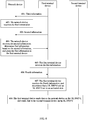
- FIG. 6 is a schematic interaction flowchart of the communication method according to this embodiment of this application. As shown in FIG. 6 , the method includes the following steps.
- Step 601 A first terminal device reports third information to a network device, where the third information is used to indicate whether the first terminal device supports data sending on a UL BWP and an SL BWP at the same time.
- the third information indicates that the first terminal device does not support data sending on the UL BWP and the SL BWP at the same time
- a subsequent process may not be performed. This case is not limited in this embodiment of this application. The following mainly describes a case in which the first terminal device supports data sending on the UL BWP and the SL BWP at the same time.
- Step 602 The network device receives the third information.
- the network device may determine, based on the third information, that the first terminal device supports data sending on the UL BWP and the SL BWP at the same time.
- Step 603 The first terminal device reports second information to the network device, where the second information includes a transmit bandwidth supported by the first terminal device.
- the second information may include one or more transmit bandwidths supported by the first terminal device.
- Step 604 The network device receives the second information, determines first information based on the second information, and sends the first information to the first terminal device, where the first information is used to configure a BWP set.
- the network device may configure one or more BWP sets for the first terminal device based on the second information.
- the second information may include one transmit bandwidth supported by the first terminal device, and the network device may configure the one or more BWP sets for the first terminal device based on the transmit bandwidth.
- the second information may include a plurality of transmit bandwidths supported by the first terminal device, and the network device may configure the one or more BWP sets for the first terminal device based on each transmit bandwidth.
- third information and the second information may be sent by using a same message, or may be sent by using different messages. This is not specifically limited.
- Step 605 The first terminal device receives the first information.
- Step 606 The network device sends fourth information to the first terminal device, where the fourth information is used to indicate to activate at least one UL BWP (for example, a UL BWP 0) and at least one SL BWP (for example, an SL BWP 0) in the BWP set.
- the fourth information is used to indicate to activate at least one UL BWP (for example, a UL BWP 0) and at least one SL BWP (for example, an SL BWP 0) in the BWP set.
- Step 607 The first terminal device receives the fourth information, and determines that the UL BWP 0 and the SL BWP 0 are in an activated state.
- Step 608 The first terminal device sends data to the network device on the UL BWP 0, and sends data to a second terminal device on the SL BWP 0.
- step numbers are merely an example of an execution procedure, and do not constitute a limitation on an execution sequence of the steps. In this embodiment of this application, there is no strict execution sequence between steps that do not have a time sequence dependency relationship with each other.
- Embodiment 2 describes only a possible interaction procedure based on Embodiment 1. For a specific implementation of each step, refer to Embodiment 1. Details are not described herein again.
- the network device or the terminal device may include corresponding hardware structures and/or software modules for performing the functions.
- the present invention can be implemented by hardware or a combination of hardware and computer software. Whether a function is performed by hardware or hardware driven by computer software depends on particular applications and design constraints of the technical solutions. A person skilled in the art may use different methods to implement the described functions for each particular application, but it should not be considered that the implementation goes beyond the scope of the present invention.
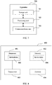
- FIG. 7 is a possible example block diagram of an apparatus according to an embodiment of this application.
- the apparatus 700 may exist in a form of software.
- the apparatus 700 may include a processing unit 702 and a communications unit 703.
- the processing unit 702 is configured to control and manage actions of the apparatus 700.
- the communications unit 703 is configured to support the apparatus 700 in communicating with another network entity.
- the apparatus 700 may further include a storage unit 701, configured to store program code and data of the apparatus 700.
- the processing unit 702 may be a processor or a controller, such as a general-purpose central processing unit (central processing unit, CPU), a general-purpose processor, a digital signal processor (digital signal processing, DSP), an application-specific integrated circuit (application specific integrated circuits, ASIC), a field programmable gate array (field programmable gate array, FPGA) or another programmable logic device, a transistor logic device, a hardware component, or any combination thereof.
- the processing unit 702 may implement or execute various example logical blocks, modules, and circuits described with reference to content disclosed in the present invention.
- the processor may be a combination of processors implementing a computing function, for example, a combination of one or more microprocessors, or a combination of the DSP and a microprocessor.
- the communications unit 703 may be a communications interface, a transceiver, a transceiver circuit, or the like.
- the communications interface is a general term. During specific implementation, the communications interface may include a plurality of interfaces.
- the storage unit 701 may be a memory.
- the apparatus 700 may be the terminal device in any one of the foregoing embodiments, or may be a semiconductor chip disposed in the terminal device.
- the processing unit 702 may support the apparatus 700 in performing actions of the terminal device in the foregoing method examples.
- the processing unit 702 mainly performs internal actions of the terminal in the method examples, and the communications unit 703 may support communication between the apparatus 700 and a network device or another terminal device.
- the communications unit performs the following steps:
- the first BWP is used for uplink communication between the first terminal device and the network device
- the second BWP is used for uplink communication between the first terminal device and the second terminal device.
- the BWP set further includes a third BWP, and the third BWP is used for downlink communication between the first terminal device and the network device.
- the communications unit is further configured to send second information to the network device, where the second information includes a radio frequency bandwidth supported by the first terminal device.
- the processing unit is configured to determine whether an offset value between a first frequency domain position and a second frequency domain position in frequency domain is less than or equal to the radio frequency bandwidth supported by the first terminal device.
- the first frequency domain position is a highest frequency domain position of the first BWP in the BWP set in frequency domain or a highest frequency domain position of the second BWP in the BWP set in frequency domain; and the second frequency domain position is a lowest frequency domain position of the first BWP in the BWP set in frequency domain or a lowest frequency domain position of the second BWP in the BWP set in frequency domain.
- the communications unit is further configured to send third information to the network device, where the third information is used to indicate whether the first terminal device supports communication on the first BWP and the second BWP at the same time.
- the communications unit is further configured to: receive fourth information, where the fourth information is used to indicate to activate the at least one first BWP or the at least one second BWP; and the first terminal device activates the at least one first BWP and the at least one second BWP based on the fourth information.
- the processing unit is configured to determine whether frame structure parameters of the at least one first BWP and the at least one second BWP are the same.
- the processing unit is further configured to determine priorities of the frame structure parameters of the at least one first BWP and the at least one second BWP; and the communications unit is configured to choose to communicate on the at least one first BWP or the at least one second BWP based on the priorities.
- the apparatus 700 may alternatively be the network device in any one of the foregoing embodiments, or may be a semiconductor chip disposed in the network device.
- the processing unit 702 may support the apparatus 700 in performing actions of the network device in the foregoing method examples.
- the processing unit 702 mainly performs internal actions of the network device in the method examples, and the communications unit 703 may support communication between the apparatus 700 and a terminal device.
- the communications unit performs the following steps: sending the first information to a first terminal device, where the first information is used to configure a BWP set; the BWP set includes a first BWP and a second BWP; and the first BWP is used for communication between the first terminal device and the network device, and the second BWP is used for communication between the first terminal device and a second terminal device.
- the first BWP is used for uplink communication between the first terminal device and the network device
- the second BWP is used for uplink communication between the first terminal device and the second terminal device.
- the BWP set further includes a third BWP, and the third BWP is used for downlink communication between the first terminal device and the network device.
- the communications unit is further configured to receive second information sent by the first terminal device, where the second information includes a radio frequency bandwidth supported by the first terminal device; the processing unit is specifically configured to determine the radio frequency bandwidth supported by the first terminal device; and the communications unit is further configured to send the first information to the first terminal device based on the radio frequency bandwidth.
- the processing unit is configured to determine whether an offset value between a first frequency domain position and a second frequency domain position in frequency domain is less than or equal to the radio frequency bandwidth supported by the first terminal device.
- the first frequency domain position is a highest frequency domain position of the first BWP in the BWP set in frequency domain or a highest frequency domain position of the second BWP in the BWP set in frequency domain; and the second frequency domain position is a lowest frequency domain position of the first BWP in the BWP set in frequency domain or a lowest frequency domain position of the second BWP in the BWP set in frequency domain.
- the communications unit is further configured to: receive third information sent by the first terminal device, where the third information is used to indicate whether the first terminal device supports communication on the first BWP and the second BWP at the same time; and send the first information to the first terminal device based on the third information if determining that the first terminal device supports the communication on the first BWP and the second BWP at the same time.
- the communications unit is further configured to send fourth information to the first terminal device, where the fourth information is used to indicate to activate the at least one first BWP or the at least one second BWP.
- FIG. 8 is a schematic structural diagram of a communications apparatus.
- the communications apparatus 800 may be the network device 101 in FIG. 2 , or may be the terminal device 1021 or the terminal device 1022 in FIG. 2 .
- the communications apparatus may be configured to implement the methods that correspond to the communications device and that are described in the foregoing method embodiments. For details, refer to the descriptions in the foregoing method embodiments.
- the communications apparatus 800 may include one or more processors 801.
- the processor 801 may also be referred to as a processing unit, and may implement a control function.
- the processor 801 may be a general-purpose processor, a dedicated processor, or the like.
- the processor 801 may be a baseband processor or a central processing unit.
- the baseband processor may be configured to process a communication protocol and communication data.
- the central processing unit may be configured to: control the communications apparatus (for example, a base station, a baseband chip, a distributed unit (distributed unit, DU), or a centralized unit (centralized unit, CU)), execute a software program, and process data of the software program.
- the processor 801 may also store instructions and/or data 803.
- the instructions and/or data 803 may be run by the processor, so that the communications apparatus 800 performs the methods that correspond to the communications device and that are described in the foregoing method embodiments.
- the processor 801 may include a transceiver unit configured to implement a receiving function and a sending function.
- the transceiver unit may be a transceiver circuit or an interface.
- a circuit or an interface configured to implement the receiving function and a circuit or an interface configured to implement the sending function may be separated or may be integrated together.
- the communications apparatus 800 may include a circuit, and the circuit may implement a sending function, a receiving function, or a communication function in the foregoing method embodiments.
- the communications apparatus 800 may include one or more memories 802.
- the memory 802 may store instructions 804, and the instructions may be run on the processor, so that the communications apparatus 800 performs the methods described in the foregoing method embodiments.
- the memory may further store data.
- the processor may further store instructions and/or data.
- the processor and the memory may be separately disposed, or may be integrated together. For example, various correspondences described in the foregoing method embodiments may be stored in the memory, or may be stored in the processor.
- the communications apparatus 800 may further include a transceiver 805 and/or an antenna 806.
- the processor 801 may be referred to as a processing unit, and controls the communications apparatus (a terminal device or a network device).
- the transceiver 805 may be referred to as a transceiver unit, a transceiver machine, a transceiver circuit, a transceiver, or the like, and is configured to implement receiving and sending functions of the communications apparatus.
- a communications apparatus 800 may include a processor 801 and a transceiver 805.
- the transceiver 805 sends, at a first time domain position, scheduling information, and sends or receives, at a second time domain position, data scheduled by using the scheduling information.
- the processor 801 determines the second time domain position based on an end position of the first time domain position and/or a capability of the terminal device.
- the processor and the transceiver described in this application may be implemented on an integrated circuit (integrated circuit, IC), an analog IC, a radio frequency integrated circuit RFIC, a hybrid signal IC, an application-specific integrated circuit (application specific integrated circuit, ASIC), a printed circuit board (printed circuit board, PCB), an electronic device, or the like.
- integrated circuit integrated circuit, IC
- analog IC analog IC
- radio frequency integrated circuit RFIC radio frequency integrated circuit
- RFIC radio frequency integrated circuit
- hybrid signal IC an application-specific integrated circuit (application specific integrated circuit, ASIC), a printed circuit board (printed circuit board, PCB), an electronic device, or the like.
- ASIC application specific integrated circuit
- PCB printed circuit board
- the processor and the transceiver may alternatively be manufactured by using various IC process technologies, for example, a complementary metal oxide semiconductor (complementary metal oxide semiconductor, CMOS), an N-type metal oxide semiconductor (nMetal-oxide-semiconductor, NMOS), a P-type metal oxide semiconductor (positive channel metal oxide semiconductor, PMOS), a bipolar junction transistor (Bipolar Junction Transistor, BJT), a bipolar CMOS (BiCMOS), silicon germanium (SiGe), and gallium arsenide (GaAs).
- CMOS complementary metal oxide semiconductor
- NMOS N-type metal oxide semiconductor
- NMOS N-type metal oxide semiconductor
- P-type metal oxide semiconductor positive channel metal oxide semiconductor
- BJT bipolar junction transistor
- BiCMOS bipolar CMOS
- SiGe silicon germanium
- GaAs gallium arsenide
- the communications apparatus is described by using the network device or the terminal device as an example.
- a scope of the communications apparatus described in this application is not limited to the example, and a structure of the communications apparatus may not be limited by FIG. 8 .
- the communications apparatus may be an independent device or may be a part of a relatively large device.
- the device may be:
- All or some of the foregoing embodiments may be implemented by using software, hardware, firmware, or any combination thereof.
- the embodiments may be implemented completely or partially in a form of a computer program product.
- the computer program product includes one or more computer instructions.
- the computer may be a general-purpose computer, a dedicated computer, a computer network, or another programmable apparatus.
- the computer instructions may be stored in a computer-readable storage medium or maybe transmitted from a computer-readable storage medium to another computer-readable storage medium.
- the computer instructions may be transmitted from a website, computer, server, or data center to another website, computer, server, or data center in a wired (for example, a coaxial cable, an optical fiber, or a digital subscriber line (DSL)) or wireless (for example, infrared, radio, or microwave) manner.
- the computer-readable storage medium may be any usable medium accessible by a computer, or a data storage device, such as a server or a data center, integrating one or more usable media.
- the usable medium may be a magnetic medium (for example, a floppy disk, a hard disk, or a magnetic tape), an optical medium (for example, a DVD), a semiconductor medium (for example, a solid-state drive (Solid State Disk, SSD)), or the like.
- a magnetic medium for example, a floppy disk, a hard disk, or a magnetic tape
- an optical medium for example, a DVD
- a semiconductor medium for example, a solid-state drive (Solid State Disk, SSD)
- the various illustrative logical units and circuits described in the embodiments of this application may implement or operate the described functions by using a general-purpose processor, a digital signal processor, an application-specific integrated circuit (ASIC), a field programmable gate array (FPGA) or another programmable logical apparatus, a discrete gate or transistor logic, a discrete hardware component, or a design of any combination thereof.
- the general-purpose processor may be a microprocessor.
- the general-purpose processor may also be any conventional processor, controller, microcontroller, or state machine.
- the processor may also be implemented by a combination of computing apparatuses, such as a digital signal processor and a microprocessor, a plurality of microprocessors, one or more microprocessors with a digital signal processor core, or any other similar configuration.
- Steps of the methods or algorithms described in the embodiments of this application may be directly embedded into hardware, a software unit executed by a processor, or a combination thereof.
- the software unit may be stored in a RAM memory, a flash memory, a ROM memory, an EPROM memory, an EEPROM memory, a register, a hard disk, a removable magnetic disk, a CD-ROM, or a storage medium of any other form in the art.
- the storage medium may be connected to a processor, so that the processor may read information from the storage medium and write information into the storage medium.
- the storage medium may further be integrated into a processor.
- the processor and the storage medium may be disposed in an ASIC, and the ASIC may be disposed in a terminal device.
- the processor and the storage medium may also be disposed in different components of a terminal device.
- These computer program instructions may also be loaded onto a computer or another programmable data processing device, so that a series of operations and steps are performed on the computer or the another programmable device, thereby generating computer-implemented processing. Therefore, the instructions executed on the computer or the another programmable device provide steps for implementing a specific function in one or more processes in the flowcharts and/or in one or more blocks in the block diagrams.
Landscapes
- Engineering & Computer Science (AREA)
- Signal Processing (AREA)
- Computer Networks & Wireless Communication (AREA)
- Mobile Radio Communication Systems (AREA)
Applications Claiming Priority (2)
| Application Number | Priority Date | Filing Date | Title |
|---|---|---|---|
| CN201811303750.0A CN111148237B (zh) | 2018-11-02 | 2018-11-02 | 一种通信方法及装置 |
| PCT/CN2019/115104 WO2020088666A1 (zh) | 2018-11-02 | 2019-11-01 | 一种通信方法及装置 |
Publications (3)
| Publication Number | Publication Date |
|---|---|
| EP3855837A1 true EP3855837A1 (de) | 2021-07-28 |
| EP3855837A4 EP3855837A4 (de) | 2021-12-08 |
| EP3855837B1 EP3855837B1 (de) | 2024-06-19 |
Family
ID=70462419
Family Applications (1)
| Application Number | Title | Priority Date | Filing Date |
|---|---|---|---|
| EP19878306.0A Active EP3855837B1 (de) | 2018-11-02 | 2019-11-01 | Kommunikationsverfahren und -vorrichtung |
Country Status (4)
| Country | Link |
|---|---|
| US (1) | US20210258958A1 (de) |
| EP (1) | EP3855837B1 (de) |
| CN (1) | CN111148237B (de) |
| WO (1) | WO2020088666A1 (de) |
Families Citing this family (7)
| Publication number | Priority date | Publication date | Assignee | Title |
|---|---|---|---|---|
| WO2020145781A1 (ko) * | 2019-01-11 | 2020-07-16 | 엘지전자 주식회사 | Nr v2x에서 bwp 기반의 사이드링크 통신을 수행하는 방법 및 장치 |
| CN111756508B (zh) * | 2019-03-29 | 2023-04-18 | 华为技术有限公司 | 一种通信方法及装置 |
| US12446003B2 (en) * | 2019-08-09 | 2025-10-14 | Lg Electronics Inc. | Method and device for configuring location of switching time |
| CN119071924A (zh) * | 2020-07-31 | 2024-12-03 | 华为技术有限公司 | 一种确定bwp的方法、装置及系统 |
| WO2022040984A1 (zh) * | 2020-08-26 | 2022-03-03 | 华为技术有限公司 | 一种通信方法与装置 |
| CN115550889B (zh) * | 2021-06-29 | 2024-09-20 | 维沃移动通信有限公司 | 传输方法、装置、设备及介质 |
| CN116094666A (zh) * | 2021-11-01 | 2023-05-09 | 中国移动通信有限公司研究院 | 传输方法、装置、设备及可读存储介质 |
Family Cites Families (21)
| Publication number | Priority date | Publication date | Assignee | Title |
|---|---|---|---|---|
| JP2018029323A (ja) * | 2016-08-10 | 2018-02-22 | ソニー株式会社 | 通信装置及び通信方法 |
| WO2018086063A1 (zh) * | 2016-11-11 | 2018-05-17 | 北京小米移动软件有限公司 | 配置工作带宽的方法及装置 |
| ES2927069T3 (es) * | 2016-12-27 | 2022-11-02 | 5G Ip Holdings Llc | Método para señalizar indicadores de parte de ancho de banda (BWP) y equipo de comunicación por radio que utiliza el mismo |
| WO2018128427A1 (en) * | 2017-01-04 | 2018-07-12 | Samsung Electronics Co., Ltd. | Method and apparatus for system information delivery in wireless communication system |
| EP4701119A3 (de) * | 2017-01-06 | 2026-04-22 | Panasonic Intellectual Property Corporation of America | Übertragung von steuerinformationen |
| CN108419295B (zh) * | 2017-02-10 | 2022-01-14 | 华为技术有限公司 | 一种终端与终端之间通信的方法、网络侧设备和终端 |
| CN108633027A (zh) * | 2017-03-24 | 2018-10-09 | 华为技术有限公司 | 通信方法及其终端设备、网络设备 |
| CN108633059B (zh) * | 2017-03-25 | 2021-06-29 | 华为技术有限公司 | 资源配置、确定部分带宽及指示部分带宽的方法及设备 |
| WO2019013564A1 (en) * | 2017-07-12 | 2019-01-17 | Lg Electronics Inc. | METHOD AND APPARATUS FOR SUPPORTING SWITCHING OF A BANDWIDTH PART IN A WIRELESS COMMUNICATION SYSTEM |
| CN108650001B (zh) * | 2017-08-11 | 2019-07-19 | 华为技术有限公司 | 一种信号加扰、解扰方法及装置 |
| CN111756516B (zh) * | 2017-08-11 | 2021-08-27 | 维沃移动通信有限公司 | 一种bwp的激活控制方法、用户设备及基站 |
| JP7374082B2 (ja) * | 2017-09-15 | 2023-11-06 | オッポ広東移動通信有限公司 | データ伝送方法、端末デバイス及びネットワークデバイス |
| RU2740707C1 (ru) * | 2017-09-15 | 2021-01-20 | Гуандун Оппо Мобайл Телекоммьюникейшнс Корп., Лтд. | Способ конфигурации ресурса, оконечное устройство и сетевое устройство |
| US10887073B2 (en) * | 2017-10-26 | 2021-01-05 | Ofinno, Llc | Activation and deactivation of bandwidth part |
| US10693620B2 (en) * | 2017-10-27 | 2020-06-23 | Ofinno, Llc | Bandwidth part configuration and operation |
| JP7182628B2 (ja) * | 2017-11-16 | 2022-12-02 | オッポ広東移動通信有限公司 | 無線通信方法、端末デバイス及びネットワークデバイス |
| CN111699739B (zh) * | 2018-02-14 | 2024-06-04 | 联想(新加坡)私人有限公司 | 确定链接的带宽部分 |
| EP4576922A3 (de) * | 2018-06-12 | 2025-08-13 | Panasonic Intellectual Property Corporation of America | Benutzergerät, basisstation und drahtloskommunikationsverfahren |
| US11917595B2 (en) * | 2018-07-03 | 2024-02-27 | Ntt Docomo, Inc. | Communication device and base station |
| US12081316B2 (en) * | 2018-08-09 | 2024-09-03 | Qualcomm Incorporated | Intra-satellite handover |
| WO2020029230A1 (en) * | 2018-08-10 | 2020-02-13 | Apple Inc. | Dynamic c-drx configuration for balance between power savings and communication efficiency, and use of dci for activating carrier components |
-
2018
- 2018-11-02 CN CN201811303750.0A patent/CN111148237B/zh active Active
-
2019
- 2019-11-01 EP EP19878306.0A patent/EP3855837B1/de active Active
- 2019-11-01 WO PCT/CN2019/115104 patent/WO2020088666A1/zh not_active Ceased
-
2021
- 2021-04-30 US US17/246,287 patent/US20210258958A1/en not_active Abandoned
Also Published As
| Publication number | Publication date |
|---|---|
| WO2020088666A1 (zh) | 2020-05-07 |
| EP3855837A4 (de) | 2021-12-08 |
| CN111148237A (zh) | 2020-05-12 |
| CN111148237B (zh) | 2022-12-30 |
| US20210258958A1 (en) | 2021-08-19 |
| EP3855837B1 (de) | 2024-06-19 |
Similar Documents
| Publication | Publication Date | Title |
|---|---|---|
| EP3855837B1 (de) | Kommunikationsverfahren und -vorrichtung | |
| CN109802799B (zh) | 用于多载波通信的载波切换方法、装置及存储介质 | |
| WO2019242511A1 (zh) | 一种参数配置方法及装置 | |
| CN110830195B (zh) | 一种信息的处理方法和通信装置 | |
| CN111130732B (zh) | 通信资源的配置方法、通信装置、通信设备及存储介质 | |
| CN114208239B (zh) | 一种新空口和新空口侧行链路切换的方法及装置 | |
| CN115191145B (zh) | 一种多prach传输方法及其装置 | |
| CN115885559B (zh) | 一种时隙结构的配置方法及其装置 | |
| CN109150463B (zh) | 信息发送、接收方法及装置 | |
| CN115280868A (zh) | 一种通信方法及装置 | |
| WO2023019410A1 (zh) | 一种传输下行控制信息dci的方法及其装置 | |
| CN114667755A (zh) | 数据传输方法和装置 | |
| JP2025020392A (ja) | 通信装置、通信方法及び集積回路 | |
| US12035417B2 (en) | Capability configuration method and apparatus for configuring a network slice of a radio access network | |
| CN115474279A (zh) | 通信方法、装置和系统 | |
| US12256376B2 (en) | Control channel transmission method and apparatus | |
| CN116724642A (zh) | 一种传输资源确定方法、装置及存储介质 | |
| CN113873644B (zh) | 通信方法及装置 | |
| CN116326051A (zh) | 一种通信方法、装置及计算机可读存储介质 | |
| US20230179371A1 (en) | Communication method and apparatus | |
| CN119997216A (zh) | 侧行通信方法、终端设备及网络设备 | |
| CN117044377A (zh) | 物理随机接入信道prach传输方法及装置 | |
| WO2023184438A1 (zh) | 一种消除时分干扰的方法及装置 | |
| CN119014070A (zh) | 用于侧行通信的方法、第一设备以及终端设备 | |
| CN118921756A (zh) | 一种通信方法、终端设备以及网络设备 |
Legal Events
| Date | Code | Title | Description |
|---|---|---|---|
| STAA | Information on the status of an ep patent application or granted ep patent |
Free format text: STATUS: THE INTERNATIONAL PUBLICATION HAS BEEN MADE |
|
| PUAI | Public reference made under article 153(3) epc to a published international application that has entered the european phase |
Free format text: ORIGINAL CODE: 0009012 |
|
| STAA | Information on the status of an ep patent application or granted ep patent |
Free format text: STATUS: REQUEST FOR EXAMINATION WAS MADE |
|
| 17P | Request for examination filed |
Effective date: 20210421 |
|
| AK | Designated contracting states |
Kind code of ref document: A1 Designated state(s): AL AT BE BG CH CY CZ DE DK EE ES FI FR GB GR HR HU IE IS IT LI LT LU LV MC MK MT NL NO PL PT RO RS SE SI SK SM TR |
|
| A4 | Supplementary search report drawn up and despatched |
Effective date: 20211110 |
|
| RIC1 | Information provided on ipc code assigned before grant |
Ipc: H04W 72/04 20090101ALI20211104BHEP Ipc: H04W 4/70 20180101ALI20211104BHEP Ipc: H04L 5/00 20060101AFI20211104BHEP |
|
| DAV | Request for validation of the european patent (deleted) | ||
| DAX | Request for extension of the european patent (deleted) | ||
| REG | Reference to a national code |
Ref country code: DE Ref legal event code: R079 Free format text: PREVIOUS MAIN CLASS: H04W0072040000 Ipc: H04L0005000000 Ref country code: DE Ref legal event code: R079 Ref document number: 602019054008 Country of ref document: DE Free format text: PREVIOUS MAIN CLASS: H04W0072040000 Ipc: H04L0005000000 |
|
| GRAP | Despatch of communication of intention to grant a patent |
Free format text: ORIGINAL CODE: EPIDOSNIGR1 |
|
| STAA | Information on the status of an ep patent application or granted ep patent |
Free format text: STATUS: GRANT OF PATENT IS INTENDED |
|
| RIC1 | Information provided on ipc code assigned before grant |
Ipc: H04W 72/0453 20230101ALI20240118BHEP Ipc: H04L 5/00 20060101AFI20240118BHEP |
|
| INTG | Intention to grant announced |
Effective date: 20240201 |
|
| GRAS | Grant fee paid |
Free format text: ORIGINAL CODE: EPIDOSNIGR3 |
|
| GRAA | (expected) grant |
Free format text: ORIGINAL CODE: 0009210 |
|
| STAA | Information on the status of an ep patent application or granted ep patent |
Free format text: STATUS: THE PATENT HAS BEEN GRANTED |
|
| AK | Designated contracting states |
Kind code of ref document: B1 Designated state(s): AL AT BE BG CH CY CZ DE DK EE ES FI FR GB GR HR HU IE IS IT LI LT LU LV MC MK MT NL NO PL PT RO RS SE SI SK SM TR |
|
| REG | Reference to a national code |
Ref country code: GB Ref legal event code: FG4D |
|
| REG | Reference to a national code |
Ref country code: CH Ref legal event code: EP |
|
| REG | Reference to a national code |
Ref country code: DE Ref legal event code: R096 Ref document number: 602019054008 Country of ref document: DE |
|
| PG25 | Lapsed in a contracting state [announced via postgrant information from national office to epo] |
Ref country code: BG Free format text: LAPSE BECAUSE OF FAILURE TO SUBMIT A TRANSLATION OF THE DESCRIPTION OR TO PAY THE FEE WITHIN THE PRESCRIBED TIME-LIMIT Effective date: 20240619 |
|
| PG25 | Lapsed in a contracting state [announced via postgrant information from national office to epo] |
Ref country code: FI Free format text: LAPSE BECAUSE OF FAILURE TO SUBMIT A TRANSLATION OF THE DESCRIPTION OR TO PAY THE FEE WITHIN THE PRESCRIBED TIME-LIMIT Effective date: 20240619 Ref country code: HR Free format text: LAPSE BECAUSE OF FAILURE TO SUBMIT A TRANSLATION OF THE DESCRIPTION OR TO PAY THE FEE WITHIN THE PRESCRIBED TIME-LIMIT Effective date: 20240619 |
|
| REG | Reference to a national code |
Ref country code: LT Ref legal event code: MG9D |
|
| PG25 | Lapsed in a contracting state [announced via postgrant information from national office to epo] |
Ref country code: GR Free format text: LAPSE BECAUSE OF FAILURE TO SUBMIT A TRANSLATION OF THE DESCRIPTION OR TO PAY THE FEE WITHIN THE PRESCRIBED TIME-LIMIT Effective date: 20240920 |
|
| REG | Reference to a national code |
Ref country code: NL Ref legal event code: MP Effective date: 20240619 |
|
| PG25 | Lapsed in a contracting state [announced via postgrant information from national office to epo] |
Ref country code: LV Free format text: LAPSE BECAUSE OF FAILURE TO SUBMIT A TRANSLATION OF THE DESCRIPTION OR TO PAY THE FEE WITHIN THE PRESCRIBED TIME-LIMIT Effective date: 20240619 |
|
| PG25 | Lapsed in a contracting state [announced via postgrant information from national office to epo] |
Ref country code: NO Free format text: LAPSE BECAUSE OF FAILURE TO SUBMIT A TRANSLATION OF THE DESCRIPTION OR TO PAY THE FEE WITHIN THE PRESCRIBED TIME-LIMIT Effective date: 20240919 Ref country code: LV Free format text: LAPSE BECAUSE OF FAILURE TO SUBMIT A TRANSLATION OF THE DESCRIPTION OR TO PAY THE FEE WITHIN THE PRESCRIBED TIME-LIMIT Effective date: 20240619 Ref country code: HR Free format text: LAPSE BECAUSE OF FAILURE TO SUBMIT A TRANSLATION OF THE DESCRIPTION OR TO PAY THE FEE WITHIN THE PRESCRIBED TIME-LIMIT Effective date: 20240619 Ref country code: GR Free format text: LAPSE BECAUSE OF FAILURE TO SUBMIT A TRANSLATION OF THE DESCRIPTION OR TO PAY THE FEE WITHIN THE PRESCRIBED TIME-LIMIT Effective date: 20240920 Ref country code: FI Free format text: LAPSE BECAUSE OF FAILURE TO SUBMIT A TRANSLATION OF THE DESCRIPTION OR TO PAY THE FEE WITHIN THE PRESCRIBED TIME-LIMIT Effective date: 20240619 Ref country code: BG Free format text: LAPSE BECAUSE OF FAILURE TO SUBMIT A TRANSLATION OF THE DESCRIPTION OR TO PAY THE FEE WITHIN THE PRESCRIBED TIME-LIMIT Effective date: 20240619 Ref country code: RS Free format text: LAPSE BECAUSE OF FAILURE TO SUBMIT A TRANSLATION OF THE DESCRIPTION OR TO PAY THE FEE WITHIN THE PRESCRIBED TIME-LIMIT Effective date: 20240919 |
|
| PG25 | Lapsed in a contracting state [announced via postgrant information from national office to epo] |
Ref country code: NL Free format text: LAPSE BECAUSE OF FAILURE TO SUBMIT A TRANSLATION OF THE DESCRIPTION OR TO PAY THE FEE WITHIN THE PRESCRIBED TIME-LIMIT Effective date: 20240619 |
|
| REG | Reference to a national code |
Ref country code: AT Ref legal event code: MK05 Ref document number: 1696666 Country of ref document: AT Kind code of ref document: T Effective date: 20240619 |
|
| PG25 | Lapsed in a contracting state [announced via postgrant information from national office to epo] |
Ref country code: NL Free format text: LAPSE BECAUSE OF FAILURE TO SUBMIT A TRANSLATION OF THE DESCRIPTION OR TO PAY THE FEE WITHIN THE PRESCRIBED TIME-LIMIT Effective date: 20240619 |
|
| PG25 | Lapsed in a contracting state [announced via postgrant information from national office to epo] |
Ref country code: PT Free format text: LAPSE BECAUSE OF FAILURE TO SUBMIT A TRANSLATION OF THE DESCRIPTION OR TO PAY THE FEE WITHIN THE PRESCRIBED TIME-LIMIT Effective date: 20241021 |
|
| PG25 | Lapsed in a contracting state [announced via postgrant information from national office to epo] |
Ref country code: PT Free format text: LAPSE BECAUSE OF FAILURE TO SUBMIT A TRANSLATION OF THE DESCRIPTION OR TO PAY THE FEE WITHIN THE PRESCRIBED TIME-LIMIT Effective date: 20241021 |
|
| PG25 | Lapsed in a contracting state [announced via postgrant information from national office to epo] |
Ref country code: PL Free format text: LAPSE BECAUSE OF FAILURE TO SUBMIT A TRANSLATION OF THE DESCRIPTION OR TO PAY THE FEE WITHIN THE PRESCRIBED TIME-LIMIT Effective date: 20240619 |
|
| PG25 | Lapsed in a contracting state [announced via postgrant information from national office to epo] |
Ref country code: EE Free format text: LAPSE BECAUSE OF FAILURE TO SUBMIT A TRANSLATION OF THE DESCRIPTION OR TO PAY THE FEE WITHIN THE PRESCRIBED TIME-LIMIT Effective date: 20240619 |
|
| PG25 | Lapsed in a contracting state [announced via postgrant information from national office to epo] |
Ref country code: AT Free format text: LAPSE BECAUSE OF FAILURE TO SUBMIT A TRANSLATION OF THE DESCRIPTION OR TO PAY THE FEE WITHIN THE PRESCRIBED TIME-LIMIT Effective date: 20240619 Ref country code: IS Free format text: LAPSE BECAUSE OF FAILURE TO SUBMIT A TRANSLATION OF THE DESCRIPTION OR TO PAY THE FEE WITHIN THE PRESCRIBED TIME-LIMIT Effective date: 20241019 |
|
| PG25 | Lapsed in a contracting state [announced via postgrant information from national office to epo] |
Ref country code: CZ Free format text: LAPSE BECAUSE OF FAILURE TO SUBMIT A TRANSLATION OF THE DESCRIPTION OR TO PAY THE FEE WITHIN THE PRESCRIBED TIME-LIMIT Effective date: 20240619 |
|
| PG25 | Lapsed in a contracting state [announced via postgrant information from national office to epo] |
Ref country code: SK Free format text: LAPSE BECAUSE OF FAILURE TO SUBMIT A TRANSLATION OF THE DESCRIPTION OR TO PAY THE FEE WITHIN THE PRESCRIBED TIME-LIMIT Effective date: 20240619 Ref country code: RO Free format text: LAPSE BECAUSE OF FAILURE TO SUBMIT A TRANSLATION OF THE DESCRIPTION OR TO PAY THE FEE WITHIN THE PRESCRIBED TIME-LIMIT Effective date: 20240619 |
|
| PG25 | Lapsed in a contracting state [announced via postgrant information from national office to epo] |
Ref country code: SM Free format text: LAPSE BECAUSE OF FAILURE TO SUBMIT A TRANSLATION OF THE DESCRIPTION OR TO PAY THE FEE WITHIN THE PRESCRIBED TIME-LIMIT Effective date: 20240619 Ref country code: ES Free format text: LAPSE BECAUSE OF FAILURE TO SUBMIT A TRANSLATION OF THE DESCRIPTION OR TO PAY THE FEE WITHIN THE PRESCRIBED TIME-LIMIT Effective date: 20240619 |
|
| PG25 | Lapsed in a contracting state [announced via postgrant information from national office to epo] |
Ref country code: SM Free format text: LAPSE BECAUSE OF FAILURE TO SUBMIT A TRANSLATION OF THE DESCRIPTION OR TO PAY THE FEE WITHIN THE PRESCRIBED TIME-LIMIT Effective date: 20240619 Ref country code: SK Free format text: LAPSE BECAUSE OF FAILURE TO SUBMIT A TRANSLATION OF THE DESCRIPTION OR TO PAY THE FEE WITHIN THE PRESCRIBED TIME-LIMIT Effective date: 20240619 Ref country code: RO Free format text: LAPSE BECAUSE OF FAILURE TO SUBMIT A TRANSLATION OF THE DESCRIPTION OR TO PAY THE FEE WITHIN THE PRESCRIBED TIME-LIMIT Effective date: 20240619 Ref country code: PL Free format text: LAPSE BECAUSE OF FAILURE TO SUBMIT A TRANSLATION OF THE DESCRIPTION OR TO PAY THE FEE WITHIN THE PRESCRIBED TIME-LIMIT Effective date: 20240619 Ref country code: IS Free format text: LAPSE BECAUSE OF FAILURE TO SUBMIT A TRANSLATION OF THE DESCRIPTION OR TO PAY THE FEE WITHIN THE PRESCRIBED TIME-LIMIT Effective date: 20241019 Ref country code: ES Free format text: LAPSE BECAUSE OF FAILURE TO SUBMIT A TRANSLATION OF THE DESCRIPTION OR TO PAY THE FEE WITHIN THE PRESCRIBED TIME-LIMIT Effective date: 20240619 Ref country code: EE Free format text: LAPSE BECAUSE OF FAILURE TO SUBMIT A TRANSLATION OF THE DESCRIPTION OR TO PAY THE FEE WITHIN THE PRESCRIBED TIME-LIMIT Effective date: 20240619 Ref country code: CZ Free format text: LAPSE BECAUSE OF FAILURE TO SUBMIT A TRANSLATION OF THE DESCRIPTION OR TO PAY THE FEE WITHIN THE PRESCRIBED TIME-LIMIT Effective date: 20240619 Ref country code: AT Free format text: LAPSE BECAUSE OF FAILURE TO SUBMIT A TRANSLATION OF THE DESCRIPTION OR TO PAY THE FEE WITHIN THE PRESCRIBED TIME-LIMIT Effective date: 20240619 |
|
| PG25 | Lapsed in a contracting state [announced via postgrant information from national office to epo] |
Ref country code: IT Free format text: LAPSE BECAUSE OF FAILURE TO SUBMIT A TRANSLATION OF THE DESCRIPTION OR TO PAY THE FEE WITHIN THE PRESCRIBED TIME-LIMIT Effective date: 20240619 |
|
| REG | Reference to a national code |
Ref country code: DE Ref legal event code: R097 Ref document number: 602019054008 Country of ref document: DE |
|
| PG25 | Lapsed in a contracting state [announced via postgrant information from national office to epo] |
Ref country code: DK Free format text: LAPSE BECAUSE OF FAILURE TO SUBMIT A TRANSLATION OF THE DESCRIPTION OR TO PAY THE FEE WITHIN THE PRESCRIBED TIME-LIMIT Effective date: 20240619 |
|
| PLBE | No opposition filed within time limit |
Free format text: ORIGINAL CODE: 0009261 |
|
| STAA | Information on the status of an ep patent application or granted ep patent |
Free format text: STATUS: NO OPPOSITION FILED WITHIN TIME LIMIT |
|
| 26N | No opposition filed |
Effective date: 20250320 |
|
| REG | Reference to a national code |
Ref country code: DE Ref legal event code: R119 Ref document number: 602019054008 Country of ref document: DE |
|
| REG | Reference to a national code |
Ref country code: CH Ref legal event code: PL |
|
| PG25 | Lapsed in a contracting state [announced via postgrant information from national office to epo] |
Ref country code: MC Free format text: LAPSE BECAUSE OF FAILURE TO SUBMIT A TRANSLATION OF THE DESCRIPTION OR TO PAY THE FEE WITHIN THE PRESCRIBED TIME-LIMIT Effective date: 20240619 |
|
| PG25 | Lapsed in a contracting state [announced via postgrant information from national office to epo] |
Ref country code: LU Free format text: LAPSE BECAUSE OF NON-PAYMENT OF DUE FEES Effective date: 20241101 |
|
| REG | Reference to a national code |
Ref country code: CH Ref legal event code: PL |
|
| PG25 | Lapsed in a contracting state [announced via postgrant information from national office to epo] |
Ref country code: CH Free format text: LAPSE BECAUSE OF NON-PAYMENT OF DUE FEES Effective date: 20241130 |
|
| REG | Reference to a national code |
Ref country code: BE Ref legal event code: MM Effective date: 20241130 |
|
| PG25 | Lapsed in a contracting state [announced via postgrant information from national office to epo] |
Ref country code: SE Free format text: LAPSE BECAUSE OF FAILURE TO SUBMIT A TRANSLATION OF THE DESCRIPTION OR TO PAY THE FEE WITHIN THE PRESCRIBED TIME-LIMIT Effective date: 20240619 |
|
| PG25 | Lapsed in a contracting state [announced via postgrant information from national office to epo] |
Ref country code: DE Free format text: LAPSE BECAUSE OF NON-PAYMENT OF DUE FEES Effective date: 20250603 |
|
| PG25 | Lapsed in a contracting state [announced via postgrant information from national office to epo] |
Ref country code: BE Free format text: LAPSE BECAUSE OF NON-PAYMENT OF DUE FEES Effective date: 20241130 |
|
| PGFP | Annual fee paid to national office [announced via postgrant information from national office to epo] |
Ref country code: GB Payment date: 20250930 Year of fee payment: 7 |
|
| PG25 | Lapsed in a contracting state [announced via postgrant information from national office to epo] |
Ref country code: FR Free format text: LAPSE BECAUSE OF NON-PAYMENT OF DUE FEES Effective date: 20241130 |
|
| PG25 | Lapsed in a contracting state [announced via postgrant information from national office to epo] |
Ref country code: IE Free format text: LAPSE BECAUSE OF NON-PAYMENT OF DUE FEES Effective date: 20241101 |
|
| PG25 | Lapsed in a contracting state [announced via postgrant information from national office to epo] |
Ref country code: HU Free format text: LAPSE BECAUSE OF FAILURE TO SUBMIT A TRANSLATION OF THE DESCRIPTION OR TO PAY THE FEE WITHIN THE PRESCRIBED TIME-LIMIT; INVALID AB INITIO Effective date: 20191101 |
|
| PG25 | Lapsed in a contracting state [announced via postgrant information from national office to epo] |
Ref country code: CY Free format text: LAPSE BECAUSE OF FAILURE TO SUBMIT A TRANSLATION OF THE DESCRIPTION OR TO PAY THE FEE WITHIN THE PRESCRIBED TIME-LIMIT; INVALID AB INITIO Effective date: 20191101 |