EP3855849A1 - Procédé de transmission et dispositif apparenté - Google Patents
Procédé de transmission et dispositif apparenté Download PDFInfo
- Publication number
- EP3855849A1 EP3855849A1 EP19862849.7A EP19862849A EP3855849A1 EP 3855849 A1 EP3855849 A1 EP 3855849A1 EP 19862849 A EP19862849 A EP 19862849A EP 3855849 A1 EP3855849 A1 EP 3855849A1
- Authority
- EP
- European Patent Office
- Prior art keywords
- channel
- uplink
- information corresponding
- sending
- priority
- Prior art date
- Legal status (The legal status is an assumption and is not a legal conclusion. Google has not performed a legal analysis and makes no representation as to the accuracy of the status listed.)
- Granted
Links
Images

Classifications
-
- H—ELECTRICITY
- H04—ELECTRIC COMMUNICATION TECHNIQUE
- H04L—TRANSMISSION OF DIGITAL INFORMATION, e.g. TELEGRAPHIC COMMUNICATION
- H04L5/00—Arrangements affording multiple use of the transmission path
- H04L5/003—Arrangements for allocating sub-channels of the transmission path
- H04L5/0058—Allocation criteria
- H04L5/0064—Rate requirement of the data, e.g. scalable bandwidth, data priority
-
- H—ELECTRICITY
- H04—ELECTRIC COMMUNICATION TECHNIQUE
- H04L—TRANSMISSION OF DIGITAL INFORMATION, e.g. TELEGRAPHIC COMMUNICATION
- H04L1/00—Arrangements for detecting or preventing errors in the information received
- H04L1/12—Arrangements for detecting or preventing errors in the information received by using return channel
- H04L1/16—Arrangements for detecting or preventing errors in the information received by using return channel in which the return channel carries supervisory signals, e.g. repetition request signals
- H04L1/18—Automatic repetition systems, e.g. Van Duuren systems
- H04L1/1812—Hybrid protocols; Hybrid automatic repeat request [HARQ]
-
- H—ELECTRICITY
- H04—ELECTRIC COMMUNICATION TECHNIQUE
- H04L—TRANSMISSION OF DIGITAL INFORMATION, e.g. TELEGRAPHIC COMMUNICATION
- H04L5/00—Arrangements affording multiple use of the transmission path
- H04L5/003—Arrangements for allocating sub-channels of the transmission path
- H04L5/0048—Allocation of pilot signals, i.e. of signals known to the receiver
-
- H—ELECTRICITY
- H04—ELECTRIC COMMUNICATION TECHNIQUE
- H04W—WIRELESS COMMUNICATION NETWORKS
- H04W52/00—Power management, e.g. Transmission Power Control [TPC] or power classes
- H04W52/04—Transmission power control [TPC]
- H04W52/06—TPC algorithms
- H04W52/14—Separate analysis of uplink or downlink
- H04W52/146—Uplink power control
-
- H—ELECTRICITY
- H04—ELECTRIC COMMUNICATION TECHNIQUE
- H04W—WIRELESS COMMUNICATION NETWORKS
- H04W72/00—Local resource management
- H04W72/12—Wireless traffic scheduling
- H04W72/1263—Mapping of traffic onto schedule, e.g. scheduled allocation or multiplexing of flows
- H04W72/1268—Mapping of traffic onto schedule, e.g. scheduled allocation or multiplexing of flows of uplink data flows
-
- H—ELECTRICITY
- H04—ELECTRIC COMMUNICATION TECHNIQUE
- H04W—WIRELESS COMMUNICATION NETWORKS
- H04W72/00—Local resource management
- H04W72/20—Control channels or signalling for resource management
- H04W72/21—Control channels or signalling for resource management in the uplink direction of a wireless link, i.e. towards the network
-
- H—ELECTRICITY
- H04—ELECTRIC COMMUNICATION TECHNIQUE
- H04W—WIRELESS COMMUNICATION NETWORKS
- H04W72/00—Local resource management
- H04W72/50—Allocation or scheduling criteria for wireless resources
- H04W72/56—Allocation or scheduling criteria for wireless resources based on priority criteria
- H04W72/566—Allocation or scheduling criteria for wireless resources based on priority criteria of the information or information source or recipient
- H04W72/569—Allocation or scheduling criteria for wireless resources based on priority criteria of the information or information source or recipient of the traffic information
-
- H—ELECTRICITY
- H04—ELECTRIC COMMUNICATION TECHNIQUE
- H04W—WIRELESS COMMUNICATION NETWORKS
- H04W74/00—Wireless channel access
- H04W74/002—Transmission of channel access control information
- H04W74/004—Transmission of channel access control information in the uplink, i.e. towards network
-
- H—ELECTRICITY
- H04—ELECTRIC COMMUNICATION TECHNIQUE
- H04W—WIRELESS COMMUNICATION NETWORKS
- H04W74/00—Wireless channel access
- H04W74/04—Scheduled access
-
- H—ELECTRICITY
- H04—ELECTRIC COMMUNICATION TECHNIQUE
- H04W—WIRELESS COMMUNICATION NETWORKS
- H04W80/00—Wireless network protocols or protocol adaptations to wireless operation
- H04W80/02—Data link layer protocols
-
- H—ELECTRICITY
- H04—ELECTRIC COMMUNICATION TECHNIQUE
- H04L—TRANSMISSION OF DIGITAL INFORMATION, e.g. TELEGRAPHIC COMMUNICATION
- H04L1/00—Arrangements for detecting or preventing errors in the information received
- H04L1/12—Arrangements for detecting or preventing errors in the information received by using return channel
- H04L1/16—Arrangements for detecting or preventing errors in the information received by using return channel in which the return channel carries supervisory signals, e.g. repetition request signals
- H04L1/18—Automatic repetition systems, e.g. Van Duuren systems
- H04L1/1867—Arrangements specially adapted for the transmitter end
- H04L1/1887—Scheduling and prioritising arrangements
-
- H—ELECTRICITY
- H04—ELECTRIC COMMUNICATION TECHNIQUE
- H04L—TRANSMISSION OF DIGITAL INFORMATION, e.g. TELEGRAPHIC COMMUNICATION
- H04L5/00—Arrangements affording multiple use of the transmission path
- H04L5/0091—Signalling for the administration of the divided path, e.g. signalling of configuration information
- H04L5/0094—Indication of how sub-channels of the path are allocated
-
- H—ELECTRICITY
- H04—ELECTRIC COMMUNICATION TECHNIQUE
- H04W—WIRELESS COMMUNICATION NETWORKS
- H04W28/00—Network traffic management; Network resource management
- H04W28/16—Central resource management; Negotiation of resources or communication parameters, e.g. negotiating bandwidth or QoS [Quality of Service]
- H04W28/18—Negotiating wireless communication parameters
- H04W28/22—Negotiating communication rate
-
- H—ELECTRICITY
- H04—ELECTRIC COMMUNICATION TECHNIQUE
- H04W—WIRELESS COMMUNICATION NETWORKS
- H04W52/00—Power management, e.g. Transmission Power Control [TPC] or power classes
- H04W52/04—Transmission power control [TPC]
- H04W52/30—Transmission power control [TPC] using constraints in the total amount of available transmission power
- H04W52/36—Transmission power control [TPC] using constraints in the total amount of available transmission power with a discrete range or set of values, e.g. step size, ramping or offsets
- H04W52/367—Power values between minimum and maximum limits, e.g. dynamic range
-
- H—ELECTRICITY
- H04—ELECTRIC COMMUNICATION TECHNIQUE
- H04W—WIRELESS COMMUNICATION NETWORKS
- H04W74/00—Wireless channel access
- H04W74/08—Non-scheduled access, e.g. ALOHA
- H04W74/0833—Random access procedures, e.g. with 4-step access
-
- H—ELECTRICITY
- H04—ELECTRIC COMMUNICATION TECHNIQUE
- H04W—WIRELESS COMMUNICATION NETWORKS
- H04W76/00—Connection management
- H04W76/10—Connection setup
- H04W76/11—Allocation or use of connection identifiers
-
- H—ELECTRICITY
- H04—ELECTRIC COMMUNICATION TECHNIQUE
- H04W—WIRELESS COMMUNICATION NETWORKS
- H04W76/00—Connection management
- H04W76/10—Connection setup
- H04W76/15—Setup of multiple wireless link connections
-
- H—ELECTRICITY
- H04—ELECTRIC COMMUNICATION TECHNIQUE
- H04W—WIRELESS COMMUNICATION NETWORKS
- H04W76/00—Connection management
- H04W76/20—Manipulation of established connections
- H04W76/27—Transitions between radio resource control [RRC] states
Definitions
- the present disclosure relates to the field of communications technologies, and in particular, to a transmission method and related devices.
- UE When user equipment (User Equipment, UE for short) simultaneously sends two or more independent uplink channels, whether the foregoing two or more uplink channels can be sent simultaneously is determined based on whether uplink power of the UE is restricted and whether the UE has the capability of simultaneously sending uplink channels. If the UE cannot simultaneously send the foregoing two or more uplink channels, the uplink channels are sent based on a sending priority order of uplink channels of a physical layer (that is, a PHY layer) specified in the protocol, which causes poorer flexibility in uplink channel sending control.
- a physical layer that is, a PHY layer
- Embodiments of the present disclosure provide a transmission method and related devices, to resolve a problem of poorer flexibility in uplink channel sending control in the related technologies.
- an embodiment of the present disclosure provides a transmission method.
- the method includes: when it is determined that N uplink channels to be sent cannot be sent simultaneously, sending at least some of the N uplink channels based on a priority corresponding to each of the N uplink channels, where
- N is an integer greater than 1
- the priority corresponding to the uplink channel is determined based on a priority determining parameter corresponding to the uplink channel, and the priority determining parameter includes at least service information corresponding to the uplink channel.
- an embodiment of the present disclosure further provides a transmission method.
- the method includes: sending a first correspondence to a terminal device, where the first correspondence is a correspondence between service information corresponding to an uplink channel and a priority corresponding to the uplink channel.
- an embodiment of the present disclosure further provides a terminal device.
- the terminal device includes: a sending module, configured to: when it is determined that N uplink channels to be sent cannot be sent simultaneously, send at least some of the N uplink channels based on a priority corresponding to each of the N uplink channels, where
- N is an integer greater than 1
- the priority corresponding to the uplink channel is determined based on a priority determining parameter corresponding to the uplink channel, and the priority determining parameter includes at least service information corresponding to the uplink channel.
- an embodiment of the present disclosure further provides a network side device.
- the network side device includes: a sending module, configured to send a first correspondence to a terminal device, where the first correspondence is a correspondence between service information corresponding to an uplink channel and a priority corresponding to the uplink channel.
- an embodiment of the present disclosure further provides a terminal device, including a processor, a memory, and a computer program stored in the memory and capable of running on the processor, where when the computer program is executed by the processor, the step of the foregoing transmission method provided in the first aspect is implemented.
- an embodiment of the present disclosure further provides a network side device, including a processor, a memory, and a computer program stored in the memory and capable of running on the processor, where when the computer program is executed by the processor, the step of the foregoing transmission method provided in the second aspect is implemented.
- an embodiment of the present disclosure further provides a computer readable storage medium, where the computer readable storage medium stores a computer program, and when the computer program is executed by the processor, the step of the foregoing transmission method provided in the first aspect is implemented or the step of the foregoing transmission method provided in the second aspect is implemented.
- the priority corresponding to the uplink channel is determined based on a priority determining parameter corresponding to the uplink channel, and the priority determining parameter includes at least service information corresponding to the uplink channel.
- a priority of each uplink channel may be respectively determined based on service information corresponding to each uplink channel, and the uplink channel may be sent based on the priority of each uplink channel.
- UE User Equipment
- UE User Equipment
- UE User Equipment
- a terminal device When user equipment (User Equipment, UE) (also referred to as a terminal device) simultaneously sends two or more independent uplink channels, whether the foregoing two or more uplink channels can be sent simultaneously is determined based on whether uplink power of the UE is restricted and whether the UE has the capability of simultaneously sending uplink channels. If the UE cannot simultaneously send the foregoing two or more uplink channels, the uplink channels are sent based on a sending priority order of uplink channels of a physical layer (that is, a PHY layer) specified in the protocol.
- the sending priority order of the uplink channels of the physical layer specified in the protocol is as follows:
- FIG. 1 is a structural diagram of a network system to which an embodiment of the present disclosure may be applied.
- the network system includes a terminal device 11 and a network side device 12.
- the terminal device 11 may be a device on a terminal device side such as a mobile phone, a tablet computer, a laptop computer, a personal digital assistant (Personal Digital Assistant, PDA for short), a mobile Internet device (Mobile Internet Device, MID), or a wearable device. It should be noted that a specific type of the terminal device 11 is not limited in this embodiment of the present disclosure.
- the network side device 12 may be a base station, for example, a macro base station, an LTE eNB, a 5G NR NB, or a gNB.
- the network side device 12 may alternatively be a small cell, for example, a low power node (Low Power Node, LPN) pico or a femto, or the network side device 12 may be an access point (Access Point, AP).
- the base station may alternatively be a network node including a central unit (Central Unit, CU) and a plurality of transmission reception points (Transmission Reception Point, TRP) managed and controlled by the central unit. It should be noted that a specific type of the network side device 12 is not limited in this embodiment of the present disclosure.
- the terminal device 11 may trigger sending of N uplink channels, and determine whether the foregoing N uplink channels can be sent simultaneously.
- N is an integer greater than 1.
- the foregoing N uplink channels may include one or at least two of a PUCCH, a PUSCH, an SRS and a PRACH.
- a quantity of each type of uplink channel may be one or at least two.
- the foregoing N uplink channels may include two PUCCHs, one PUSCH, and two PRACHs.
- the terminal device 11 may directly determine some uplink channels from the N uplink channels and abandon sending some uplink channels that are determined. For example, some uplink channels that need to be abandoned for sending may be randomly selected from the foregoing N uplink channels. It may be understood that this implementation can also determine, based on channel selection parameters except a priority, some uplink channels that need to be sent, or determine some uplink channels that need to be abandoned for sending.
- the terminal device 11 may respectively determine, based on a priority determining parameter corresponding to each of the N uplink channels, a priority corresponding to each uplink channel, and send at least some of the N uplink channels based on the priority corresponding to each uplink channel. For example, uplink channels whose priorities are in the top M are sent, where M is a quantity of uplink channels that can be simultaneously sent by the terminal device 11.
- the priority determining parameter corresponding to the foregoing uplink channel may include at least service information corresponding to the uplink channel.
- the service information corresponding to the uplink channel may include at least one of service type information corresponding to data included in the uplink channel and service type information corresponding to triggering of uplink channel sending.
- the priority determining parameter corresponding to the uplink channel may also include first information used to indicate information about uplink channels that cannot be sent simultaneously.
- the first information may include at least one of the following: identification information of a channel, second information used to indicate a reason why the N uplink channels cannot be sent simultaneously, a channel sending priority determined by a physical layer, a quantity of uplink channels that can be sent simultaneously, and the like.
- the network side device 12 may send a first correspondence to the terminal device 11, where the first correspondence is a correspondence between the service information corresponding to the uplink channel and the priority corresponding to the uplink channel. Therefore, the terminal device 11 may determine the priority corresponding to each uplink channel based on the first correspondence and the service information corresponding to each uplink channel.
- the terminal device 11 may simultaneously send the foregoing N uplink channels.
- the network side device 12 may receive the uplink channels sent by the terminal device 11.
- the priority of each uplink channel may be respectively determined based on the service information corresponding to each uplink channel, and the uplink channel may be sent based on the priority of the uplink channel, so that flexibility of uplink channel sending can be improved.
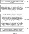
- FIG. 2 is a flowchart of a transmission method according to an embodiment of the present disclosure. As shown in FIG. 2 , the method includes the following steps: Step 201: When it is determined that N uplink channels to be sent cannot be sent simultaneously, send at least some of the N uplink channels based on a priority corresponding to each of the N uplink channels.
- N is an integer greater than 1
- the priority corresponding to the uplink channel is determined based on a priority determining parameter corresponding to the uplink channel, and the priority determining parameter includes at least service information corresponding to the uplink channel.
- a terminal device for example, media access control (Medium Access Control, MAC) of the terminal device) layer or a physical layer (that is, a PHY layer) may determine, after triggering sending of the N uplink channels, whether the foregoing N uplink channels can be sent simultaneously. For example, the terminal device may determine, based on a sending power of each of the N uplink channels and whether physical resources of each uplink channel are occupied, whether the foregoing N uplink channels can be sent simultaneously.
- MAC Medium Access Control
- simultaneous sending of the foregoing N uplink channels may mean that sending of the foregoing N uplink channels overlaps in time.
- a sending time of an uplink channel 1 is [tl, t2]
- a sending time of an uplink channel 2 is [t3, t4], where t2 is greater than t3 and less than or equal to t4, that is, [tl, t2] and [t3, t4] overlap.
- the priority corresponding to each uplink channel may be determined based on the priority determining parameter corresponding to each of the foregoing N uplink channels, and at least some of the foregoing N uplink channels may be sent based on the priority corresponding to each uplink channel.
- the priority determining parameter corresponding to the foregoing uplink channel may include at least service information corresponding to the uplink channel.
- priorities corresponding to uplink channels are respectively determined based on service information corresponding to each of the foregoing N uplink channels, (for example, if a PUSCH includes data whose logical channel priority is 1, it is determined that a priority of the PUSCH is 1; and if an SR triggering condition of a PUCCH is triggering of data whose logical channel priority is 2, it is determined that a priority of the PUCCH is 2), and uplink channels whose priorities are in the top M are sent, where M is a quantity of uplink channels that can be simultaneously sent by the terminal device.
- the transmission method when it is determined that the N uplink channels to be sent cannot be sent simultaneously, at least some of the N uplink channels are sent based on the priority corresponding to each of the N uplink channels, where N is an integer greater than 1, the priority corresponding to the uplink channel is determined based on the priority determining parameter corresponding to the uplink channel, and the priority determining parameter includes at least the service information corresponding to the uplink channel.
- the priority of each uplink channel is respectively determined based on the service information corresponding to each uplink channel, and the uplink channel is sent based on the priority of each uplink channel.
- the service information corresponding to the uplink channel includes at least one of the following:
- the service information corresponding to the uplink channel may include the service type information corresponding to the data included in the uplink channel.
- the service information corresponding to the uplink channel may be service type information corresponding to data included in the PUSCH or the PUCCH.
- the service information corresponding to the uplink channel may also include the service type information corresponding to the triggering of the uplink channel sending.
- the uplink channel is a PRACH or an SRS channel
- the service information corresponding to the uplink channel may be service type information corresponding to triggering of PRACH or SRS sending.
- service type information corresponding to data included in the PUSCH includes at least one of the following: information corresponding to a logical channel of the data included in the PUSCH, a type of a Media Access Control control element MAC CE, and a priority of the Media Access Control control element MAC CE; and/or when the uplink channel includes a physical uplink control channel PUCCH, service type information corresponding to data included in the PUCCH includes at least one of the following: a data type, and service information corresponding to the data type; and/or when the uplink channel includes a physical random access channel PRACH, service type information corresponding to triggering of PRACH sending includes at least one of the following: a type of a trigger event that triggers the PRACH sending, and information corresponding to a logical channel that triggers the PRACH sending; and/or when the uplink channel includes a sounding reference signal SRS channel, service type information corresponding to triggering of SRS sending includes: a type of
- the service information corresponding to the uplink channel may include the service type information corresponding to the data included in the PUSCH, where the service type information corresponding to the data included in the PUSCH may include but is not limited to at least one of the following: the information corresponding to the logical channel of the data included in the PUSCH, the type of the MAC control element (Control Element, CE), and the priority of the MAC CE.
- the service type information corresponding to the data included in the PUSCH may include but is not limited to at least one of the following: the information corresponding to the logical channel of the data included in the PUSCH, the type of the MAC control element (Control Element, CE), and the priority of the MAC CE.
- the foregoing information corresponding to the logical channel of the data included in the PUSCH may include but is not limited to at least one of the following: an identifier of the logical channel, a priority of the logical channel, a cell corresponding to the logical channel, a cell group corresponding to the logical channel, a data type corresponding to the logical channel, a control signaling type corresponding to the logical channel, and the like.
- the foregoing type of the MAC CE may include but is not limited to a buffer status report (Buffer Status Report, BSR), a power headroom report (Power Headroom Report, PHR), or the like.
- the foregoing priority of the MAC CE for example, a priority of a MAC CE of a cell radio network temporary identifier (Cell Radio Network Temporary Identifier, C-RNTI), is the highest.
- the service information corresponding to the uplink channel may include the service type information corresponding to the data included in the PUCCH, where the service type information corresponding to the data included in the PUCCH may include but is not limited to at least one of the following: the data type, and the service information corresponding to the data type.
- the foregoing data type may include but is not limited to an SR, HARQ feedback, a CSI report, or the like.
- the foregoing service information corresponding to the data type may mean service information corresponding to a data type included in the PUCCH.
- the foregoing service information corresponding to the data type includes service information corresponding to the SR (for example, information corresponding to a logical channel that triggers SR sending).
- the service information corresponding to the data type may include information corresponding to a logical channel that triggers SR sending; and/or when the data type includes hybrid automatic repeat request HARQ feedback, the service information corresponding to the data type may include information corresponding to a logical channel that triggers HARQ sending; and/or when the data type includes a channel state information CSI report, the service information corresponding to the data type may include a trigger type that triggers the CSI report.
- the foregoing information corresponding to the logical channel that triggers the SR sending or the foregoing information corresponding to the logical channel that triggers the HARQ sending may include but is not limited to at least one of the following: an identifier of the logical channel, a priority of the logical channel, a cell corresponding to the logical channel, a cell group corresponding to the logical channel, a data type corresponding to the logical channel, a control signaling type corresponding to the logical channel, and the like.
- the foregoing trigger type that triggers the CSI report may include a periodic report, an aperiodic report, a semi-persistent report, or the like.
- the service information corresponding to the uplink channel includes service type information corresponding to triggering of PRACH sending, where the service type information corresponding to triggering of PRACH sending may include but is not limited to at least one of the following: a type of a trigger event that triggers the PRACH sending, and information corresponding to a logical channel that triggers the PRACH sending.
- the type of the trigger event that triggers the PRACH sending may include at least one of the following:
- the foregoing state transition of radio resource control (Radio Resource Control, RRC) in the inactive state is, for example, transition the RRC from the inactive state to a connected state.
- Radio Resource Control Radio Resource Control
- the service information corresponding to the uplink channel includes service type information corresponding to triggering of SRS sending, where the service type information corresponding to the triggering of the SRS sending may include a type of a trigger event that triggers the SRS sending.
- the type of the trigger event that triggers the SRS sending may include at least one of the following: periodic sending, aperiodic sending, semi-persistent sending, and the like.
- the information corresponding to the logical channel includes at least one of the following:
- the foregoing information corresponding to the logical channel may be the information corresponding to the logical channel of the data included in the PUSCH, the information corresponding to the logical channel that triggers the PRACH sending, the information corresponding to the logical channel that triggers the SR sending, or the information corresponding to the logical channel that triggers the HARQ sending.
- the foregoing identifier of the logical channel may be, for example, a logical channel 1 and a logical channel 2.
- the foregoing priority of the logical channel may be, for example, a priority 1 of the logical channel.
- the foregoing cell group corresponding to the logical channel may be, for example, a master cell group (Master Cell Group, MCG) or a secondary cell group (Secondary Cell Group, SCG).
- the foregoing data type corresponding to the logical channel may be, for example, RRC signaling or ordinary data (for example, data corresponding to a dedicated traffic channel (Dedicated Traffic Channel, DTCH)).
- the foregoing control signaling type corresponding to the logical channel may be, for example, common control channel (Common Control Channel, CCCH) control signaling or dedicated control channel (Dedicated Control Channel, DCCH) control signaling.
- the service information corresponding to the uplink channel is determined based on priorities of the at least two sets of data from the service type information corresponding to the at least two sets of data.
- the service information corresponding to the uplink channel may be determined based on priorities of the at least two sets of data. For example, service type information corresponding to data whose priority is the highest or lowest in the two sets of data included in the uplink channel is determined as the service information corresponding to the uplink channel.
- the terminal device may use the logical channel priority 1 as the service information corresponding to the PUSCH.
- the PUCCH includes HARQ feedback of the logical channel priority 1 and HARQ feedback of the logical channel priority 2
- the terminal device may use the logical channel priority 1 as the service information corresponding to the PUCCH.
- the service type information corresponding to the data whose priority is the highest or lowest in the two sets of data included in the uplink channel is determined as the service information corresponding to the uplink channel.
- the priority corresponding to the uplink channel is determined based on a first correspondence and the service information corresponding to the uplink channel, and the first correspondence is a correspondence between the service information corresponding to the uplink channel and the priority corresponding to the uplink channel.
- the foregoing first correspondence may be predefined in a protocol, or may be configured on a network side.
- the terminal device may respectively search, based on the service information corresponding to each of the N uplink channels, a priority corresponding to the service information from the first correspondence as the priority corresponding to each uplink channel. For example, based on service information corresponding to an uplink channel 1, a priority corresponding to the service information is searched from the first correspondence as the priority corresponding to the uplink channel 1; and based on service information corresponding to an uplink channel 2, a priority corresponding to the service information is searched from the first correspondence as the priority corresponding to the uplink channel 2.
- the priority corresponding to the uplink channel is determined based on the first correspondence and the service information corresponding to the uplink channel, so that efficiency of determining the priority corresponding to the uplink channel can be improved, and then efficiency of uplink channel sending can be improved.
- the first correspondence may be predefined in a protocol.
- the method further includes: receiving the first correspondence sent by a network side device.
- the first correspondence sent by the network side device is received.
- flexibility of configuration of the correspondence between the service information corresponding to the uplink channel and the priority corresponding to the uplink channel can be improved.
- the sending at least some of the N uplink channels based on a priority corresponding to each of the N uplink channels includes: when the priority corresponding to each of the N uplink channels is the same, randomly selecting M uplink channels from the N uplink channels for sending, where M is a quantity of uplink channels that can be sent simultaneously.
- the terminal device may randomly select two uplink channels from the PUSCH#1, the PUSCH#2, and the PUSCH#3 for sending.
- M uplink channels are randomly selected from the N uplink channels for sending, so that uplink channels can be sent when priorities corresponding the uplink channels are the same, and flexibility of uplink channel sending is improved.
- the priority determining parameter further includes first information, and the first information is used to indicate information about uplink channels that cannot be sent simultaneously.
- the first information is used to indicate information about the uplink channels that cannot be sent simultaneously.
- the first information may include but is not limited to at least one of the following: identification information of a channel, a channel sending priority determined by a physical layer, information used to indicate a reason why the N uplink channels cannot be sent simultaneously, a quantity of uplink channels that can be sent simultaneously, and the like.
- the terminal device may determine the priority corresponding to the uplink channel with reference to both the first information and the service information corresponding to the uplink channel.
- the physical layer indicates that a priority of a PUSCH#1 (for example, a PUSCH of a PCell) is higher than a priority of a PUSCH#2 (for example, a PUSCH of SCell).
- the priorities of the PUSCH#1 and the PUSCH#2 determined based on service information corresponding to uplink channels are the same (for example, priorities of logical channels corresponding to data included in the PUSCH#1 and the PUSCH#2 are the same), it is determined that the priority of the PUSCH#1 is higher than that of the PUSCH#2, that is, the PUSCH#1 is sent first.
- the priority corresponding to the uplink channel determined based on the service information corresponding to the uplink channel may be preferentially considered.
- the uplink channel may be directly sent based on the priority corresponding to each uplink channel determined based on the service information corresponding to each uplink channel.
- the uplink channel may be sent with reference to the foregoing first information.
- the first information includes at least one of the following:
- the foregoing identification information of the channel may include but is not limited to at least one of the following: a type of the channel, a cell identifier to which the channel belongs, a cell group identifier to which the channel belongs, a cell type identifier to which the channel belongs, an uplink carrier identifier to which the channel belongs, and the like.
- the foregoing second information is information used to indicate a reason why the N uplink channels cannot be sent simultaneously, for example, information used to indicate that the sending power exceeds the maximum sending power allowed by the terminal device, information used to indicate that simultaneous sending cannot be implemented due to sending condition restrictions, information used to indicate that physical resources of the uplink channel are occupied, and the like.
- the foregoing channel sending priority determined by the physical layer may be a priority determined based on an uplink channel sending priority of the physical layer specified in a protocol.
- the identification information of the channel includes at least one of the following:
- the foregoing type of the channel may include but is not limited to a PUCCH, a PUSCH, an SRS, a PRACH, or the like.
- the foregoing cell identifier to which the channel belongs is, for example, a serving cell 1.
- the foregoing cell group identifier to which the channel belongs is, for example, an MCG or an SCG.
- the foregoing cell type identifier to which the channel belongs is, for example, a primary cell (Primary Cell, PCell), a secondary cell (Secondary Cell, SCell), a primary secondary cell (Primary Secondary Cell, PSCell), a special cell (Special Cell, SpCell), or a PUCCH SCell.
- the foregoing uplink carrier identifier to which the channel belongs is, for example, supplementary uplink (Supplementary Uplink, SUL) or normal uplink (Normal Uplink, NUL).
- the sending power exceeds the maximum sending power allowed by the terminal device.
- the terminal device may indicate a sending power of each uplink channel, and a sum of uplink sending powers when N uplink channels are sent simultaneously exceeds the maximum sending power allowed by the terminal device. Simultaneous sending cannot be implemented due to sending condition restrictions. For example, because a PRACH and a PUCCH cannot be coded simultaneously, the PRACH and the PUCCH cannot be sent simultaneously in one cell. Physical resources of the uplink channel are occupied. For example, the physical resources are occupied by another terminal device, or the physical resources are occupied in advance by another channel of the terminal device (that is, a channel other than the foregoing N channels).
- the method before the sending at least some of the N uplink channels based on a priority corresponding to each of the N uplink channels, the method further includes: indicating, by a physical layer of the terminal device, the first information to a media access control MAC layer.
- the priority corresponding to each of the N uplink channels may be determined by the MAC layer. Specifically, when it is determined that the N uplink channels cannot be sent simultaneously, the physical layer may indicate the foregoing first information to the MAC layer. Therefore, the MAC layer may determine the priority corresponding to each uplink channel based on the first information and the service information corresponding to each uplink channel.
- the method before the sending at least some of the N uplink channels based on a priority corresponding to each of the N uplink channels, the method further includes: determining, by the MAC layer based on the first information and the service information corresponding to each of the N uplink channels, the priority corresponding to each of the N uplink channels.
- the MAC layer can directly learn the service information corresponding to each uplink channel. Therefore, the MAC layer determines, based on the first information and the service information corresponding to each of the N uplink channels, the priority corresponding to each of the N uplink channels, so that transmission of data between layers of the terminal device can be reduced, and resources can be saved.
- the uplink channel that needs to be sent may be determined based on the priority corresponding to each of the N uplink channels, and is indicated to the physical layer, and the corresponding uplink channel is sent by the physical layer.
- the method before the sending at least some of the N uplink channels based on a priority corresponding to each of the N uplink channels, the method further includes:
- the priority corresponding to each of the N uplink channels may be determined by the physical layer. Specifically, when sending of the N uplink channels is triggered, the MAC layer may indicate, to the physical layer, the service information corresponding to each of the N uplink channels. When it is determined that the N uplink channels cannot be sent simultaneously, the physical layer may determine, based on the service information corresponding to each of the N uplink channels, the priority corresponding to each of the N uplink channels.
- the uplink channel that needs to be sent may be determined based on the priority corresponding to each of the N uplink channels, and is sent.
- the physical layer may alternatively determine, with reference to the first information and the service information corresponding to each of the N uplink channels, the priority corresponding to each of the N uplink channels. For example, when the priority corresponding to each uplink channel determined based on the service information corresponding to each uplink channel is the same, the uplink channel is sent with reference to the first information.
- the physical layer determines, based on the service information corresponding to each of the N uplink channels, the priority corresponding to each of the N uplink channels. Therefore, the physical layer may directly determine, based on the priority corresponding to each of the N uplink channels, the uplink channel that needs to be sent, and send the uplink channel. Compared with that the uplink channel that needs to be sent is indicated by the MAC layer, efficiency of uplink channel sending can be improved.
- Example 1 The uplink channel that may be finally sent is determined by the MAC layer.
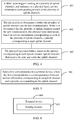
- the transmission method provided in this embodiment of the present disclosure may include the following steps:
- Step 301 The MAC layer triggers sending of a plurality of uplink channels.
- the foregoing plurality of uplink channels to be sent include any combination of one or more of the following:
- Step 302 The physical layer determines whether the plurality of uplink channels can be sent simultaneously. When it is determined that the plurality of uplink channels cannot be sent simultaneously, the physical layer performs target processing.
- the target processing includes at least one of the following:
- Step 303 When the MAC layer determines, based on the information that is about the uplink channels that cannot be sent simultaneously and that is indicated by the physical layer, that the plurality of uplink channels cannot be sent simultaneously, the MAC layer respectively determines, based on service information corresponding to each uplink channel, a priority corresponding to each uplink channel, and determines, based on the priority corresponding to each uplink channel, uplink channels that need to be sent.
- a PUSCH includes data whose logical channel priority is 1, it is determined that a priority of the PUSCH is 1; and if an SR triggering condition of a PUCCH is triggering of data whose logical channel priority is 2, it is determined that a priority of the PUCCH is 2.
- the uplink channels may be sent with reference to the foregoing information about the uplink channels that cannot be sent simultaneously (that is, the first information).
- the physical layer indicates that a priority of a PUSCH#1 (for example, a PUSCH of a PCell) is higher than a priority of a PUSCH#2 (for example, a PUSCH of SCell).
- a priority of a PUSCH#1 for example, a PUSCH of a PCell
- a priority of a PUSCH#2 for example, a PUSCH of SCell.
- Step 304 The MAC layer indicates, to the physical layer, the uplink channels that need to be sent for sending.
- the priority corresponding to each of the N uplink channels may be determined by the MAC layer, so that transmission of data between layers of the terminal device can be reduced, and resources can be saved.
- channels that can be sent are determined based on service information of the channels, so as to ensure that channels having higher service priorities can be successfully sent.
- Example 2 The uplink channel that may be finally sent is determined by the physical layer.
- the transmission method provided in this embodiment of the present disclosure may include the following steps:
- Step 401 The MAC layer triggers sending of a plurality of uplink channels, and indicates, to the physical layer, service information corresponding to each of the plurality of uplink channels.
- the MAC layer may immediately indicate, to the physical layer when triggering sending of the plurality of uplink channels, service information corresponding to each of the plurality of uplink channels, or indicate, to the physical layer after the physical layer determines that the plurality of uplink channels cannot be sent simultaneously, service information corresponding to each of the plurality of uplink channels.
- Step 402 The physical layer determines whether the plurality of uplink channels can be sent simultaneously. When it is determined that the plurality of uplink channels cannot be sent simultaneously, the physical layer determines, based on service information corresponding to each of the plurality of uplink channels, a priority corresponding to each uplink channel.
- the physical layer may alternatively determine, with reference to the first information and the service information corresponding to each of the N uplink channels, the priority corresponding to each of the N uplink channels. For example, when the priority corresponding to each uplink channel determined based on the service information corresponding to each uplink channel is the same, the uplink channel is sent with reference to the first information.
- Step 403 The physical layer determines, based on the priority corresponding to each uplink channel, uplink channels that need to be sent, and sends the uplink channels.
- a sending order of uplink channels may be determined based on priorities of the uplink channels. For example, if an uplink channel priority of a PUSCH that includes a logical channel priority 1 is 1, and an uplink channel priority of a PRACH triggered by data of a logical channel priority 2 is 2, the physical layer determines that sending of the PUSCH is prior to sending of the PRACH.
- the physical layer determines, based on the service information corresponding to each of the N uplink channels, the priority corresponding to each of the N uplink channels. Therefore, the physical layer may directly determine, based on the priority corresponding to each of the N uplink channels, the uplink channel that needs to be sent, and send the uplink channel. Compared with that the uplink channel that needs to be sent is indicated by the MAC layer, efficiency of uplink channel sending can be improved.
- channels that can be sent are determined based on service information of the channels, so as to ensure that channels having higher service priorities can be successfully sent.
- FIG. 5 is a flowchart of another transmission method according to an embodiment of the present disclosure. As shown in FIG. 5 , the method includes the following steps: Step 501: Send a first correspondence to a terminal device, where the first correspondence is a correspondence between service information corresponding to an uplink channel and a priority corresponding to the uplink channel.
- the network side device may send the first correspondence to the terminal device, so that the terminal device may determine, based on the first correspondence and the service information corresponding to the uplink channel, the priority corresponding to the uplink channel.
- the network side device may receive the uplink channel sent by the terminal device.
- the service information corresponding to the uplink channel may include at least one of the following:
- service type information corresponding to data included in the PUSCH includes at least one of the following: information corresponding to a logical channel of the data included in the PUSCH, a type of a Media Access Control control element MAC CE, and a priority of the Media Access Control control element MAC CE; and/or when the uplink channel includes a physical uplink control channel PUCCH, service type information corresponding to data included in the PUCCH includes at least one of the following: a data type, and service information corresponding to the data type; and/or when the uplink channel includes a physical random access channel PRACH, service type information corresponding to triggering of PRACH sending includes at least one of the following: a type of a trigger event that triggers the PRACH sending, and information corresponding to a logical channel that triggers the PRACH sending; and/or when the uplink channel includes a sounding reference signal SRS channel, service type information corresponding to triggering of SRS sending includes: a type of
- the service information corresponding to the data type includes information corresponding to a logical channel that triggers SR sending; and/or when the data type includes hybrid automatic repeat request HARQ feedback, the service information corresponding to the data type includes information corresponding to a logical channel that triggers HARQ sending; and/or when the data type includes a channel state information CSI report, the service information corresponding to the data type includes a trigger type that triggers the CSI report.
- the information corresponding to the logical channel may include at least one of the following:
- the type of the trigger event that triggers the PRACH sending may include at least one of the following:
- the network side device sends the first correspondence to the terminal device, where the first correspondence is the correspondence between the service information corresponding to the uplink channel and the priority corresponding to the uplink channel, so that flexibility of configuration of the first correspondence can be improved.
- FIG. 6 is a structural diagram of a terminal device according to an embodiment of the present disclosure. As shown in FIG. 6 , the terminal device 600 includes a sending module 601.
- the sending module 601 is configured to: when it is determined that N uplink channels to be sent cannot be sent simultaneously, send at least some of the N uplink channels based on a priority corresponding to each of the N uplink channels.
- N is an integer greater than 1
- the priority corresponding to the uplink channel is determined based on a priority determining parameter corresponding to the uplink channel, and the priority determining parameter includes at least service information corresponding to the uplink channel.
- the service information corresponding to the uplink channel includes at least one of the following:
- service type information corresponding to data included in the PUSCH includes at least one of the following: information corresponding to a logical channel of the data included in the PUSCH, a type of a Media Access Control control element MAC CE, and a priority of the Media Access Control control element MAC CE; and/or when the uplink channel includes a physical uplink control channel PUCCH, service type information corresponding to data included in the PUCCH includes at least one of the following: a data type, and service information corresponding to the data type; and/or when the uplink channel includes a physical random access channel PRACH, service type information corresponding to triggering of PRACH sending includes at least one of the following: a type of a trigger event that triggers the PRACH sending, and information corresponding to a logical channel that triggers the PRACH sending; and/or when the uplink channel includes a sounding reference signal SRS channel, service type information corresponding to triggering of SRS sending includes: a type of
- the service information corresponding to the data type includes information corresponding to a logical channel that triggers SR sending; and/or when the data type includes hybrid automatic repeat request HARQ feedback, the service information corresponding to the data type includes information corresponding to a logical channel that triggers HARQ sending; and/or when the data type includes a channel state information CSI report, the service information corresponding to the data type includes a trigger type that triggers the CSI report.
- the information corresponding to the logical channel includes at least one of the following:
- the type of the trigger event that triggers the PRACH sending includes at least one of the following:
- the service information corresponding to the uplink channel is determined based on priorities of the at least two sets of data from the service type information corresponding to the at least two sets of data.
- the priority corresponding to the uplink channel is determined based on a first correspondence and the service information corresponding to the uplink channel, and the first correspondence is a correspondence between the service information corresponding to the uplink channel and the priority corresponding to the uplink channel.
- the first correspondence is predefined in a protocol.
- the terminal device further includes: a receiving module, configured to receive the first correspondence sent by a network side device.
- the sending at least some of the N uplink channels based on a priority corresponding to each of the N uplink channels includes: when the priority corresponding to each of the N uplink channels is the same, randomly selecting M uplink channels from the N uplink channels for sending, where M is a quantity of uplink channels that can be sent simultaneously.
- the priority determining parameter further includes first information, and the first information is used to indicate information about uplink channels that cannot be sent simultaneously.
- the first information includes at least one of the following:
- the identification information of the channel includes at least one of the following:
- the terminal device further includes: a first indication module, configured to: before at least some of the N uplink channels are sent based on the priority corresponding to each of the N uplink channels, indicate the first information to a media access control MAC layer by using a physical layer of the terminal device.
- a first indication module configured to: before at least some of the N uplink channels are sent based on the priority corresponding to each of the N uplink channels, indicate the first information to a media access control MAC layer by using a physical layer of the terminal device.
- the terminal device further includes: a first determining module, configured to: before at least some of the N uplink channels are sent based on the priority corresponding to each of the N uplink channels, determine, by using the MAC layer based on the first information and the service information corresponding to each of the N uplink channels, the priority corresponding to each of the N uplink channels.
- a first determining module configured to: before at least some of the N uplink channels are sent based on the priority corresponding to each of the N uplink channels, determine, by using the MAC layer based on the first information and the service information corresponding to each of the N uplink channels, the priority corresponding to each of the N uplink channels.
- the terminal device further includes:
- the terminal device 600 provided in this embodiment of the present disclosure can implement processes implemented by the terminal device in the method embodiments of FIG. 2 to FIG. 5 . To avoid repetition, details are not described herein again.
- the sending module 601 is configured to: when it is determined that the N uplink channels to be sent cannot be sent simultaneously, send at least some of the N uplink channels based on the priority corresponding to each of the N uplink channels, where N is an integer greater than 1, the priority corresponding to the uplink channel is determined based on the priority determining parameter corresponding to the uplink channel, and the priority determining parameter includes at least the service information corresponding to the uplink channel.
- the priority of each uplink channel may be respectively determined based on the service information corresponding to each uplink channel, and the uplink channel may be sent based on the priority of each uplink channel. Compared with uplink channel sending performed based on a priority of each uplink channel specified in a protocol in the related technologies, flexibility of uplink channel sending is improved.
- FIG. 7 is a structural diagram of a network side device according to an embodiment of the present disclosure.
- the network side device 700 includes a sending module 701.
- the sending module is configured to send a first correspondence to a terminal device, where the first correspondence is a correspondence between service information corresponding to an uplink channel and a priority corresponding to the uplink channel.
- the network side device 700 provided in this embodiment of the present disclosure can implement processes implemented by the network side device in the method embodiments of FIG. 2 to FIG. 5 . To avoid repetition, details are not described herein again.
- the sending module 701 is configured to send the first correspondence to the terminal device, where the first correspondence is the correspondence between the service information corresponding to the uplink channel and the priority corresponding to the uplink channel, so that flexibility of configuration of the first correspondence can be improved.
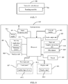
- FIG. 8 is a structural diagram of another terminal device according to an embodiment of the present disclosure.
- the terminal device 800 includes but is not limited to: a radio frequency unit 801, a network module 802, an audio output unit 803, an input unit 804, a sensor 805, a display unit 806, a user input unit 807, an interface unit 808, a memory 809, a processor 810, a power supply 811, and other components.
- a radio frequency unit 801 includes but is not limited to: a radio frequency unit 801, a network module 802, an audio output unit 803, an input unit 804, a sensor 805, a display unit 806, a user input unit 807, an interface unit 808, a memory 809, a processor 810, a power supply 811, and other components.
- the terminal device may include more or fewer components than that shown in the figure, or a combination of some components, or an arrangement of different components.
- the terminal device includes but is not limited to a mobile phone, a tablet computer, a notebook computer, a
- the radio frequency unit 801 is configured to: when it is determined that N uplink channels to be sent cannot be sent simultaneously, send at least some of the N uplink channels based on a priority corresponding to each of the N uplink channels, where N is an integer greater than 1, the priority corresponding to the uplink channel is determined based on a priority determining parameter corresponding to the uplink channel, and the priority determining parameter includes at least service information corresponding to the uplink channel.
- the priority of each uplink channel may be respectively determined based on the service information corresponding to each uplink channel, and the uplink channel may be sent based on the priority of each uplink channel.
- the uplink channel sending performed based on a priority of each uplink channel specified in a protocol in the related technologies, flexibility of uplink channel sending is improved.
- the service information corresponding to the uplink channel includes at least one of the following:
- service type information corresponding to data included in the PUSCH includes at least one of the following: information corresponding to a logical channel of the data included in the PUSCH, a type of a Media Access Control control element MAC CE, and a priority of the Media Access Control control element MAC CE; and/or when the uplink channel includes a physical uplink control channel PUCCH, service type information corresponding to data included in the PUCCH includes at least one of the following: a data type, and service information corresponding to the data type; and/or when the uplink channel includes a physical random access channel PRACH, service type information corresponding to triggering of PRACH sending includes at least one of the following: a type of a trigger event that triggers the PRACH sending, and information corresponding to a logical channel that triggers the PRACH sending; and/or when the uplink channel includes a sounding reference signal SRS channel, service type information corresponding to triggering of SRS sending includes: a type of
- the service information corresponding to the data type includes information corresponding to a logical channel that triggers SR sending; and/or when the data type includes hybrid automatic repeat request HARQ feedback, the service information corresponding to the data type includes information corresponding to a logical channel that triggers HARQ sending; and/or when the data type includes a channel state information CSI report, the service information corresponding to the data type includes a trigger type that triggers the CSI report.
- the information corresponding to the logical channel includes at least one of the following:
- the type of the trigger event that triggers the PRACH sending includes at least one of the following:
- the service information corresponding to the uplink channel is determined based on priorities of the at least two sets of data from the service type information corresponding to the at least two sets of data.
- the priority corresponding to the uplink channel is determined based on a first correspondence and the service information corresponding to the uplink channel, and the first correspondence is a correspondence between the service information corresponding to the uplink channel and the priority corresponding to the uplink channel.
- the first correspondence is predefined in a protocol.
- the radio frequency unit 801 is further configured to: receive the first correspondence sent by a network side device.
- the processor 810 is configured to: when the priority corresponding to each of the N uplink channels is the same, randomly select M uplink channels from the N uplink channels for sending, where M is a quantity of uplink channels that can be sent simultaneously.
- the priority determining parameter further includes first information, and the first information is used to indicate information about uplink channels that cannot be sent simultaneously.
- the first information includes at least one of the following:
- the identification information of the channel includes at least one of the following:
- the processor 810 is further configured to: before at least some of the N uplink channels are sent based on the priority corresponding to each of the N uplink channels, indicate the first information to a media access control MAC layer by using a physical layer of the terminal device.
- the processor 810 is further configured to: before at least some of the N uplink channels are sent based on the priority corresponding to each of the N uplink channels, determine, by using the MAC layer based on the first information and the service information corresponding to each of the N uplink channels, the priority corresponding to each of the N uplink channels.
- processor 810 is further configured to:
- the radio frequency unit 801 may be configured to receive and transmit information, or receive and transmit signals during a call. Specifically, the radio frequency unit 801 receives downlink data from a base station, and transmits the downlink data to the processor 810 for processing; and in addition, transmits uplink data to the base station.
- the radio frequency unit 801 includes but is not limited to an antenna, at least one amplifier, a transceiver, a coupler, a low noise amplifier, a duplexer, and the like.
- the radio frequency unit 801 may also communicate with another device through a wireless communications system and network.
- the terminal device provides a user with wireless broadband Internet access through the network module 802, for example, helps the user send and receive emails, browse web pages, and access streaming media.
- the audio output unit 803 may convert audio data received by the radio frequency unit 801 or the network module 802 or stored in the memory 809 into an audio signal, and output the audio signal into sound.
- the audio output unit 803 may also provide audio output related to a specific function performed by the terminal 800 (for example, call signal receiving sound or message receiving sound).
- the audio output unit 803 includes a speaker, a buzzer, a receiver, and the like.
- the input unit 804 is configured to receive an audio signal or a video signal.
- the input unit 804 may include a graphics processing unit (Graphics Processing Unit, GPU) 8041 and a microphone 8042.
- the graphics processing unit 8041 is configured to process image data of a static picture or a video obtained by an image capture apparatus (for example, a camera) in video capture mode or image capture mode.
- a processed image frame may be displayed on the display unit 806.
- the image frame processed by the graphics processing unit 8041 may be stored in the memory 809 (or another storage medium) or sent via the radio frequency unit 801 or the network module 802.
- the microphone 8042 may receive sound and can process such sound into audio data. Processed audio data may be converted, in telephone call mode, into a format that may be sent to a mobile communication base station via the radio frequency unit 801 for output.
- the terminal device 800 further includes at least one sensor 805, such as a light sensor, a motion sensor, and other sensors.
- the light sensor includes an ambient light sensor and a proximity sensor, where the ambient light sensor may adjust brightness of the display panel 8061 based on brightness of ambient light, and the proximity sensor may turn off the display panel 8061 and/or backlight when the terminal device 800 moves towards the ear.
- an accelerometer sensor may detect magnitude of acceleration in various directions (usually three axes), may detect magnitude and the direction of gravity when stationary, may be configured to identify postures of the terminal device (such as horizontal and vertical screen switch, related games, and magnetometer posture calibration), may perform functions related to vibration identification (such as a pedometer and a knock), and the like.
- the sensor 805 may further include a fingerprint sensor, a pressure sensor, an iris sensor, a molecular sensor, a gyroscope, a barometer, a hygrometer, a thermometer, an infrared sensor, or the like. Details are not described herein.
- the display unit 806 is configured to display information input by the user or information provided to the user.
- the display unit 806 may include the display panel 8061, and the display panel 8061 may be configured in a form of a liquid crystal display (Liquid Crystal Display, LCD), an organic light-emitting diode (Organic Light-Emitting Diode, OLED), or the like.
- LCD Liquid Crystal Display
- OLED Organic Light-Emitting Diode
- the user input unit 807 may be configured to receive input numeric or character information, and generate key signal inputs related to user settings and function control of the terminal device.
- the user input unit 807 includes a touch panel 8071 and another input device 8072.
- the touch panel 8071 also called a touch screen, may collect a touch operation of the user on or near the touch panel 8071 (For example, the user uses any suitable object or accessory such as a finger or a stylus to operate on or near the touch panel 8071).
- the touch panel 8071 may include two parts: a touch detection apparatus and a touch controller.
- the touch detection apparatus detects a touch position of the user, detects a signal brought by the touch operation, and transmits the signal to the touch controller.
- the touch controller receives touch information from the touch detection apparatus, converts the touch information into contact coordinates, transmits the contact coordinates to the processor 810, receives a command sent by the processor 810, and executes the command.
- the touch panel 8071 may be implemented in various types such as resistive, capacitive, infrared, and surface acoustic wave.
- the user input unit 807 may further include the another input device 8072.
- the another input device 8072 may include but is not limited to a physical keyboard, function keys (such as a volume control key and a switch key), a trackball, a mouse, and a joystick. Details are not described herein.
- the touch panel 8071 may cover the display panel 8061.
- the touch panel 8071 transmits the touch operation to the processor 810 to determine a type of a touch event. Then the processor 810 provides corresponding visual output on the display panel 8061 based on the type of the touch event.
- the touch panel 8071 and the display panel 8061 are configured as two independent components to implement input and output functions of the terminal device, in some embodiments, the touch panel 8071 and the display panel 8061 may be integrated to implement the input and output functions of the terminal device. Details are not limited herein.
- the interface unit 808 is an interface for connecting an external apparatus to the terminal device 800.
- the external apparatus may include a wired or wireless headphone port, an external power supply (or a battery charger) port, a wired or wireless data port, a storage card port, a port used to connect to an apparatus having an identity module, an audio input/output (I/O) port, a video I/O port, an earphone port, and the like.
- the interface unit 808 may be configured to receive an input (for example, data information and power) from the external apparatus and transmit the received input to one or more elements in the terminal device 800, or transmit data between the terminal device 800 and the external apparatus.
- the memory 809 may be configured to store software programs and various data.
- the memory 809 may mainly include a program storage area and a data storage area.
- the program storage area may store an operating system, an application program required by at least one function (such as a sound playback function and an image playback function), and the like.
- the data storage area may store data (such as audio data and a phone book) created based on use of the mobile phone, and the like.
- the memory 809 may include a high-speed random access memory or a nonvolatile memory, for example, at least one disk storage device, a flash memory, or another volatile solid-state storage device.
- the processor 810 is a control center of the terminal device, connects various parts of the entire terminal device by using various interfaces and circuits, and performs various functions of the terminal device and processes data by running or executing the software programs and/or the modules stored in the memory 809 and invoking data stored in the memory 809, so as to monitor the terminal device as a whole.
- the processor 810 may include one or more processing units.
- the processor 810 may integrate an application processor with a modem processor.
- the application processor mainly processes the operating system, a user interface, the application program, and the like, and the modem processor mainly processes wireless communication. It may be understood that the foregoing modem processor may not be integrated into the processor 810.
- the terminal device 800 may further include the power supply 811 (for example, a battery) configured to supply power to various components.
- the power supply 811 may be logically connected to the processor 810 through a power management system, so as to implement functions such as managing charging, discharging, and power consumption through the power management system.
- the terminal device 800 includes some function modules not shown. Details are not described herein.
- an embodiment of the present disclosure further provides a terminal device, including the processor 810, the memory 809, and a computer program stored in the memory 809 and capable of running on the processor 810, where when the computer program is executed by the processor 810, the processes of the foregoing embodiments of the transmission method are implemented, and the same technical effects can be achieved. To avoid repetition, details are not described herein again.
- FIG. 9 is a structural diagram of another network side device according to an embodiment of the present disclosure.
- the network side device 900 includes a processor 901, a memory 902, a bus interface 903, and a transceiver 904, where the processor 901, the memory 902, and the transceiver 904 are all connected to the bus interface 903.
- the network side device 900 further includes a computer program stored in the memory 902 and capable of running on the processor 901.
- the computer program is executed by the processor 901, the following step is implemented: sending a first correspondence to a terminal device, where the first correspondence is a correspondence between service information corresponding to an uplink channel and a priority corresponding to the uplink channel.
- An embodiment of the present disclosure further provides a network side device, including the processor 901, the memory 902, and a computer program stored in the memory 902 and capable of running on the processor 901, where when the computer program is executed by the processor 901, the processes of the foregoing embodiments of the transmission method are implemented, and the same technical effects can be achieved. To avoid repetition, details are not described herein again.
- An embodiment of the present disclosure further provides a computer readable storage medium, storing a computer program, where when the computer program is executed by the processor, the processes of the foregoing embodiments of the transmission method are implemented, and the same technical effects can be achieved. To avoid repetition, details are not described herein again.
- the computer readable storage medium is, for example, a read-only memory (Read-Only Memory, ROM for short), a random access memory (Random Access Memory, RAM for short), a magnetic disk, or an optical disk.
- the computer software product is stored in a storage medium (for example, a ROM/RAM, a magnetic disk, or a compact disc), and includes a plurality of instructions for instructing a terminal (which may be a mobile phone, a computer, a server, an air conditioner, a network device, or the like) to perform the method described in the embodiments of the present disclosure.
- a storage medium for example, a ROM/RAM, a magnetic disk, or a compact disc
- a terminal which may be a mobile phone, a computer, a server, an air conditioner, a network device, or the like
Landscapes
- Engineering & Computer Science (AREA)
- Signal Processing (AREA)
- Computer Networks & Wireless Communication (AREA)
- Mobile Radio Communication Systems (AREA)
Applications Claiming Priority (2)
| Application Number | Priority Date | Filing Date | Title |
|---|---|---|---|
| CN201811095578.4A CN110933763B (zh) | 2018-09-19 | 2018-09-19 | 一种传输方法及相关设备 |
| PCT/CN2019/103015 WO2020057335A1 (fr) | 2018-09-19 | 2019-08-28 | Procédé de transmission et dispositif apparenté |
Publications (4)
| Publication Number | Publication Date |
|---|---|
| EP3855849A1 true EP3855849A1 (fr) | 2021-07-28 |
| EP3855849A4 EP3855849A4 (fr) | 2021-11-24 |
| EP3855849C0 EP3855849C0 (fr) | 2025-12-24 |
| EP3855849B1 EP3855849B1 (fr) | 2025-12-24 |
Family
ID=69856062
Family Applications (1)
| Application Number | Title | Priority Date | Filing Date |
|---|---|---|---|
| EP19862849.7A Active EP3855849B1 (fr) | 2018-09-19 | 2019-08-28 | Procédé de transmission et dispositif apparenté |
Country Status (10)
| Country | Link |
|---|---|
| US (1) | US11910431B2 (fr) |
| EP (1) | EP3855849B1 (fr) |
| JP (1) | JP7317949B2 (fr) |
| KR (1) | KR102749890B1 (fr) |
| CN (1) | CN110933763B (fr) |
| AU (1) | AU2019343226B2 (fr) |
| CA (1) | CA3113134A1 (fr) |
| ES (1) | ES3058592T3 (fr) |
| SG (1) | SG11202102699SA (fr) |
| WO (1) | WO2020057335A1 (fr) |
Families Citing this family (6)
| Publication number | Priority date | Publication date | Assignee | Title |
|---|---|---|---|---|
| CN115428566B (zh) * | 2020-04-10 | 2025-09-19 | 富士通株式会社 | 发送数据的方法、装置和通信系统 |
| CN113841452B (zh) * | 2020-04-23 | 2025-07-08 | 北京小米移动软件有限公司 | 发送数据的方法、装置、用户设备及存储介质 |
| WO2022028553A1 (fr) * | 2020-08-06 | 2022-02-10 | Essen Innovation Company Limited | Procédé, équipement utilisateur et support lisible par ordinateur non transitoire pour une priorisation basée sur une couche physique sans priorisation basée sur un canal logique |
| CN114258135B (zh) | 2020-09-25 | 2025-07-11 | 维沃移动通信有限公司 | 上行信道传输方法、装置及终端 |
| WO2023055105A1 (fr) * | 2021-09-30 | 2023-04-06 | 엘지전자 주식회사 | Procédé de mise en œuvre d'une procédure d'accès à un canal, et dispositif associé |
| CN116198315A (zh) | 2021-11-30 | 2023-06-02 | 通用汽车环球科技运作有限责任公司 | 用于动力传动系统的动力输出机构的系统 |
Family Cites Families (22)
| Publication number | Priority date | Publication date | Assignee | Title |
|---|---|---|---|---|
| CN101742651A (zh) * | 2008-11-24 | 2010-06-16 | 大唐移动通信设备有限公司 | 一种上行物理信道数据的发送方法及设备 |
| WO2011120716A1 (fr) * | 2010-04-01 | 2011-10-06 | Panasonic Corporation | Commande de puissance de transmission pour des canaux d'accès aléatoire physiques |
| EP2244514A1 (fr) * | 2009-04-23 | 2010-10-27 | Panasonic Corporation | Procédure de priorisation de canal logique pour générer plusieurs blocs de transport de liaison montante |
| US8638815B2 (en) * | 2010-01-08 | 2014-01-28 | Blackberry Limited | Method and apparatus for logical channel prioritization for uplink carrier aggregation |
| JP5898087B2 (ja) * | 2010-11-05 | 2016-04-06 | パナソニック インテレクチュアル プロパティ コーポレーション オブアメリカPanasonic Intellectual Property Corporation of America | 無線通信端末装置及び電力割当方法 |
| US9930677B2 (en) * | 2010-12-07 | 2018-03-27 | Sharp Kabushiki Kaisha | Prioritizing multiple channel state information (CSI) reporting with carrier aggregation |
| JP5727100B2 (ja) * | 2011-09-21 | 2015-06-03 | エルジー エレクトロニクス インコーポレイティド | 上りリンク信号伝送電力を制御する端末装置及びその方法 |
| US8964780B2 (en) * | 2012-01-25 | 2015-02-24 | Ofinno Technologies, Llc | Sounding in multicarrier wireless communications |
| CN102665284B (zh) * | 2012-04-13 | 2014-09-17 | 华为技术有限公司 | 上行业务传输调度方法和终端 |
| EP3451750B1 (fr) * | 2012-05-31 | 2021-04-21 | Interdigital Patent Holdings, Inc. | Commande de puissance de liaison transversale de dispositif à dispositif (d2d) |
| JP6159523B2 (ja) * | 2012-12-11 | 2017-07-05 | 株式会社Nttドコモ | ユーザ装置及び送信制御方法 |
| US11470619B2 (en) * | 2013-08-07 | 2022-10-11 | Interdigital Patent Holdings, Inc. | Coverage enhancements of low cost MTC devices in uplink/downlink decoupled scenario |
| US9264963B2 (en) | 2013-08-21 | 2016-02-16 | Intel Corporation | User equipment and method for enhanced uplink power control |
| MY195735A (en) | 2014-03-14 | 2023-02-08 | Apple Inc | Uplink Channel Transmission in Dual Connectivity |
| JP5864691B1 (ja) | 2014-09-25 | 2016-02-17 | 株式会社Nttドコモ | ユーザ端末、無線通信方法及び無線通信システム |
| US10264602B2 (en) * | 2015-04-15 | 2019-04-16 | Apple Inc. | Controlled OFDMA random access |
| CN108282855B (zh) | 2017-01-06 | 2024-06-18 | 华为技术有限公司 | 上行功率控制方法及终端 |
| CN108347760B (zh) * | 2017-01-22 | 2021-06-08 | 华为技术有限公司 | 一种上行信道的功率分配方法及装置 |
| WO2018143741A1 (fr) | 2017-02-05 | 2018-08-09 | 엘지전자 주식회사 | Procédé de transmission d'un canal partagé de liaison montante physique dans un système de communication sans fil et dispositif correspondant |
| CN109392126A (zh) * | 2017-08-10 | 2019-02-26 | 华为技术有限公司 | 上行传输方法、终端设备和网络设备 |
| US10849165B2 (en) * | 2018-04-06 | 2020-11-24 | Mediatek Inc. | Handling of simultaneous transmission of PRACH and other uplink channels in mobile communications |
| US20200036473A1 (en) * | 2018-07-24 | 2020-01-30 | Mediatek Singapore Pte. Ltd. | Uplink Control Information And Physical Uplink Control Channel Transmission Enhancement In Mobile Communications |
-
2018
- 2018-09-19 CN CN201811095578.4A patent/CN110933763B/zh active Active
-
2019
- 2019-08-28 JP JP2021515642A patent/JP7317949B2/ja active Active
- 2019-08-28 EP EP19862849.7A patent/EP3855849B1/fr active Active
- 2019-08-28 KR KR1020217010615A patent/KR102749890B1/ko active Active
- 2019-08-28 AU AU2019343226A patent/AU2019343226B2/en active Active
- 2019-08-28 CA CA3113134A patent/CA3113134A1/fr active Pending
- 2019-08-28 SG SG11202102699SA patent/SG11202102699SA/en unknown
- 2019-08-28 WO PCT/CN2019/103015 patent/WO2020057335A1/fr not_active Ceased
- 2019-08-28 ES ES19862849T patent/ES3058592T3/es active Active
-
2021
- 2021-03-18 US US17/205,817 patent/US11910431B2/en active Active
Also Published As
| Publication number | Publication date |
|---|---|
| CA3113134A1 (fr) | 2020-03-26 |
| KR102749890B1 (ko) | 2025-01-02 |
| KR20210057120A (ko) | 2021-05-20 |
| SG11202102699SA (en) | 2021-04-29 |
| EP3855849C0 (fr) | 2025-12-24 |
| AU2019343226B2 (en) | 2022-09-08 |
| US20210212085A1 (en) | 2021-07-08 |
| AU2019343226A1 (en) | 2021-05-13 |
| EP3855849A4 (fr) | 2021-11-24 |
| CN110933763B (zh) | 2022-02-08 |
| US11910431B2 (en) | 2024-02-20 |
| ES3058592T3 (en) | 2026-03-11 |
| JP7317949B2 (ja) | 2023-07-31 |
| CN110933763A (zh) | 2020-03-27 |
| WO2020057335A1 (fr) | 2020-03-26 |
| JP2022500949A (ja) | 2022-01-04 |
| EP3855849B1 (fr) | 2025-12-24 |
Similar Documents
| Publication | Publication Date | Title |
|---|---|---|
| US11910431B2 (en) | Transmission method and related devices | |
| WO2021027821A1 (fr) | Procédé de traitement de sdt, dispositif et système | |
| US11877339B2 (en) | Channel access method, configuration method, terminal, and network side device | |
| US12302400B2 (en) | Random access method, configuration method, terminal, and network side device | |
| US12512894B2 (en) | Beam failure handling method and terminal | |
| WO2020151703A1 (fr) | Procédé et appareil d'accès aléatoire, et dispositif de communication | |
| EP3813469A1 (fr) | Procédé d'accès aléatoire et dispositif de communication | |
| AU2019348064B2 (en) | Method for Processing Terminal Device Capability Information, Terminal Device, and Network-Side Device | |
| US20210204329A1 (en) | Random access method and terminal | |
| CN113473605A (zh) | 一种冲突资源确定方法和终端 | |
| HK40046971A (en) | Transmission method and related device | |
| RU2777610C1 (ru) | Способ передачи и связанные с ним устройства | |
| HK40046971B (en) | Transmission method and related device | |
| US12133264B2 (en) | Method for selecting random access request resource, terminal, and network device | |
| US11711852B2 (en) | Random access method and terminal device | |
| HK40067663A (en) | Method for dealing with occurrence of beam failure, and terminal | |
| HK40067214A (en) | Method for selecting random access request resource, terminal, and network device | |
| HK40047579A (en) | Terminal device capability information processing method, terminal device and network side device | |
| HK40047580A (en) | Random access method and terminal |
Legal Events
| Date | Code | Title | Description |
|---|---|---|---|
| STAA | Information on the status of an ep patent application or granted ep patent |
Free format text: STATUS: THE INTERNATIONAL PUBLICATION HAS BEEN MADE |
|
| PUAI | Public reference made under article 153(3) epc to a published international application that has entered the european phase |
Free format text: ORIGINAL CODE: 0009012 |
|
| STAA | Information on the status of an ep patent application or granted ep patent |
Free format text: STATUS: REQUEST FOR EXAMINATION WAS MADE |
|
| 17P | Request for examination filed |
Effective date: 20210407 |
|
| AK | Designated contracting states |
Kind code of ref document: A1 Designated state(s): AL AT BE BG CH CY CZ DE DK EE ES FI FR GB GR HR HU IE IS IT LI LT LU LV MC MK MT NL NO PL PT RO RS SE SI SK SM TR |
|
| REG | Reference to a national code |
Ref country code: HK Ref legal event code: DE Ref document number: 40046971 Country of ref document: HK |
|
| A4 | Supplementary search report drawn up and despatched |
Effective date: 20211022 |
|
| RIC1 | Information provided on ipc code assigned before grant |
Ipc: H04L 1/18 20060101ALI20211018BHEP Ipc: H04W 72/12 20090101ALI20211018BHEP Ipc: H04W 52/36 20090101ALI20211018BHEP Ipc: H04W 28/22 20090101ALI20211018BHEP Ipc: H04L 5/00 20060101ALI20211018BHEP Ipc: H04W 74/00 20090101AFI20211018BHEP |
|
| DAV | Request for validation of the european patent (deleted) | ||
| DAX | Request for extension of the european patent (deleted) | ||
| GRAP | Despatch of communication of intention to grant a patent |
Free format text: ORIGINAL CODE: EPIDOSNIGR1 |
|
| STAA | Information on the status of an ep patent application or granted ep patent |
Free format text: STATUS: GRANT OF PATENT IS INTENDED |
|
| INTG | Intention to grant announced |
Effective date: 20250728 |
|
| GRAS | Grant fee paid |
Free format text: ORIGINAL CODE: EPIDOSNIGR3 |
|
| GRAA | (expected) grant |
Free format text: ORIGINAL CODE: 0009210 |
|
| STAA | Information on the status of an ep patent application or granted ep patent |
Free format text: STATUS: THE PATENT HAS BEEN GRANTED |
|
| AK | Designated contracting states |
Kind code of ref document: B1 Designated state(s): AL AT BE BG CH CY CZ DE DK EE ES FI FR GB GR HR HU IE IS IT LI LT LU LV MC MK MT NL NO PL PT RO RS SE SI SK SM TR |
|
| REG | Reference to a national code |
Ref country code: CH Ref legal event code: F10 Free format text: ST27 STATUS EVENT CODE: U-0-0-F10-F00 (AS PROVIDED BY THE NATIONAL OFFICE) Effective date: 20251224 Ref country code: GB Ref legal event code: FG4D |
|
| REG | Reference to a national code |
Ref country code: DE Ref legal event code: R096 Ref document number: 602019079663 Country of ref document: DE |
|
| U01 | Request for unitary effect filed |
Effective date: 20260113 |
|
| U07 | Unitary effect registered |
Designated state(s): AT BE BG DE DK EE FI FR IT LT LU LV MT NL PT RO SE SI Effective date: 20260127 |
|
| REG | Reference to a national code |
Ref country code: ES Ref legal event code: FG2A Ref document number: 3058592 Country of ref document: ES Kind code of ref document: T3 Effective date: 20260311 |