EP3855988B1 - Unité de service adaptative d'une machine à boissons - Google Patents
Unité de service adaptative d'une machine à boissons Download PDFInfo
- Publication number
- EP3855988B1 EP3855988B1 EP19773849.5A EP19773849A EP3855988B1 EP 3855988 B1 EP3855988 B1 EP 3855988B1 EP 19773849 A EP19773849 A EP 19773849A EP 3855988 B1 EP3855988 B1 EP 3855988B1
- Authority
- EP
- European Patent Office
- Prior art keywords
- recipient
- beverage
- machine
- seat
- service unit
- Prior art date
- Legal status (The legal status is an assumption and is not a legal conclusion. Google has not performed a legal analysis and makes no representation as to the accuracy of the status listed.)
- Active
Links
Images


Classifications
-
- A—HUMAN NECESSITIES
- A47—FURNITURE; DOMESTIC ARTICLES OR APPLIANCES; COFFEE MILLS; SPICE MILLS; SUCTION CLEANERS IN GENERAL
- A47J—KITCHEN EQUIPMENT; COFFEE MILLS; SPICE MILLS; APPARATUS FOR MAKING BEVERAGES
- A47J31/00—Apparatus for making beverages
- A47J31/44—Parts or details or accessories of beverage-making apparatus
- A47J31/4403—Constructional details
-
- A—HUMAN NECESSITIES
- A47—FURNITURE; DOMESTIC ARTICLES OR APPLIANCES; COFFEE MILLS; SPICE MILLS; SUCTION CLEANERS IN GENERAL
- A47J—KITCHEN EQUIPMENT; COFFEE MILLS; SPICE MILLS; APPARATUS FOR MAKING BEVERAGES
- A47J31/00—Apparatus for making beverages
- A47J31/44—Parts or details or accessories of beverage-making apparatus
- A47J31/46—Dispensing spouts, pumps, drain valves or like liquid transporting devices
Definitions
- the field of the invention pertains to beverage preparation machines, e.g. to machines using capsules of an ingredient of the beverage to be prepared, the machine having a removable unit, e.g. an ingredient supply or collecting unit, that has an adaptive arrangement.
- a removable unit e.g. an ingredient supply or collecting unit
- a "beverage” is meant to include any human-consumable liquid substance, such as tea, coffee, hot or cold chocolate, milk, soup, baby food, etc...
- a “capsule” is meant to include any pre-portioned beverage ingredient, such as a flavouring ingredient, within an enclosing packaging of any material, in particular an airtight packaging, e.g. plastic, aluminium, recyclable and/or biodegradable packagings, and of any shape and structure, including soft pods or rigid cartridges containing the ingredient.
- the capsule may contain an amount of ingredient for preparing a single beverage portion or a plurality of beverage portions.
- Certain beverage preparation machines use capsules containing ingredients to be extracted or to be dissolved and/or ingredients that are stored and dosed automatically in the machine or else are added at the time of preparation of the drink.
- Some beverage machines possess filling means that include a pump for liquid, usually water, which pumps the liquid from a source of water that is cold or indeed heated through heating means, e.g. a thermoblock or the like.
- a capsule containing beverage ingredients is inserted in a brewing device.
- the brewing device is tightly closed about the capsule, water is injected at the first face of the capsule, the beverage is produced in the closed volume of the capsule and a brewed beverage can be drained from a second face of the capsule and collected into a receptacle such as a cup or glass.
- the machine may include a mixing unit, such as a unit operating with an ingredient-containing capsule that that is combined in the mixing unit with a liquid, e.g. water, to form a beverage.
- a mixing unit such as a unit operating with an ingredient-containing capsule that that is combined in the mixing unit with a liquid, e.g. water, to form a beverage.
- mixing units have been developed to facilitate insertion of a "fresh" capsule and removal of the capsule upon use.
- the mixing unit comprise two parts relatively movable from a configuration for inserting/removing a capsule to a configuration for brewing the ingredient in the capsule.
- the actuation of the movable part of the mixing unit may be manual as disclosed in WO 2009/043630 , WO 01/15581 , WO 02/43541 , WO 2010/015427 , WO 2010/128109 , WO 2011/144719 and WO 2012/032019 .
- Various handle configurations are disclosed in EP 1867260 , WO 2005/004683 , WO WO2007/135136 , WO 2008/138710 , WO 2009/074550 , WO 2009/074553 , WO 2009/074555 , WO 2009/074557 , WO 2009/074559 , WO 2010/037806 , WO 2011/042400 , WO 2011/042401 and WO 2011/144720 . Integrations of such arrangements into beverage machines are disclosed in WO 2009/074550 , WO2011/144719 , EP2014195046 , EP2014195048 and EP2014195067 .
- the actuation of the movable part of the mixing unit may be motorized, as for example disclosed in EP 1 767 129 , WO 2012/025258 , WO 2012/025259 and WO 2013/127476 .
- a beverage machine typically includes a housing containing a beverage processing module and a water tank in fluid communication with the beverage processing module.
- beverage machines are disclosed in EP 1 208 782 , EP 1 267 687 , EP 1 686 879 , EP 1 731 065 , EP 1 829 469 , EP 1 864 598 , EP 1 865 815 , EP 1 867 260 , EP 1 878 368 , EP 2 222 210 , EP 2 222 211 , EP 2 222 212 , EP 2 227 121 , EP 2 227 122 , US 2008/0006159 , US 7,165,488 , WO 2007/111884 , WO 2009/074553 , WO 2010/015427 , WO 2011/089210 and WO 2012/055767 .
- the water tank is removable to be refilled by a user when empty.
- Some systems include a continuous water supply by connecting the beverage machine to the city water distribution network.
- the invention relates to a machine for preparing a beverage according to claim 1.
- the beverage preparation machine can be an in-home or out of home machine.
- the machine may be for the preparation of coffee, tea, chocolate, cacao, milk, soup, baby food, etc...
- the beverage preparation typically includes the mixing of a plurality of beverage ingredients, e.g. water and milk powder, and/or the infusion of a beverage ingredient, such as an infusion of ground coffee or tea with water.
- a beverage ingredient such as an infusion of ground coffee or tea with water.
- One or more of such ingredients may be supplied in loose and/or agglomerate powder form and/or in liquid form, in particular in a concentrate form.
- a carrier or diluent liquid, e.g. water may be mixed with such ingredient to form the beverage.
- a predetermined amount of beverage is formed and dispensed on user-request, which corresponds to a portion (e.g. a serving) .
- the volume of such portion may be in the range of 25 to 200 ml and even up to 300 or 400 ml, e.g.
- a coffee machine may be configured for dispensing espressos, e.g. an adjustable volume of 20 to 60 ml per portion, and/or for dispensing lungos, e.g. a volume in the range of 70 to 150 ml per portion.
- the machine of the invention has a body with a seat and a beverage processing line extending from a liquid inlet to a beverage dispenser.
- the liquid inlet may be connected to a source of liquid, e.g. water, such as a machine tank and/or an external liquid supply line, e.g. a domestic water supply line.
- a source of liquid e.g. water
- an external liquid supply line e.g. a domestic water supply line.
- the beverage outlet is typically located above a placement location for a beverage recipient, e.g. a cup or a mug.
- processing lines, machine tanks, external liquid supply lines, outlets and their connections can be found in WO 2009/130099 , WO 2010/006953 , WO 2010/046442 , WO 2010/128109 , WO 2011/083103 , WO 2011/089210 , WO 2011/095502 , WO 2011/144723 , WO 2012/055765 , WO 2012/055767 , WO 2012/072758 , WO 2013/127907 , WO 2016/005348 , WO 2016/005349 , WO 2016/005350 , WO 2016/005351 , WO 2017/081055 , WO 2017/118713 , WO 2018/069266 , WO 2018/069268 and EP2228633 .
- the placement location can be associated with a machine recipient support for supporting such user-recipient under the outlet.
- the support can be: associated with a drip tray e.g. a drip tray supporting the support; and/or movable relative to the housing vertically under the outlet and/or away from under the outlet for enabling a placement of user-recipients of different heights under the outlet.
- EP 0 549 887 EP 1 440 639 , EP 1 731 065 , EP 1 867 260 , US 5,161,455 , US 5,353,692 , WO 2009/074557 , WO 2009/074559 , WO 2009/135869 , WO 2011/154492 , WO 2012/007313 , WO 2013/186339 , EP 2014198712 , EP 2014198710 and EP 2014198715 .
- the liquid line can extend via a pump for pumping the liquid and/or a thermal conditioner such as a heater and/or a cooler for thermally conditioning the liquid.
- a thermal conditioner such as a heater and/or a cooler for thermally conditioning the liquid.
- the pump can be arranged for driving the liquid from the liquid inlet to the dispenser, e.g. a solenoid pump (reciprocating piston pump) or a peristaltic pump or a diaphragm pump.
- a solenoid pump reciprocating piston pump
- a peristaltic pump or a diaphragm pump.
- Examples of pumps and their incorporation into beverage machines are disclosed in WO 2009/150030 , WO 2010/108700 , WO 2011/107574 , WO 2013/098173 and WO 2018/001750 .
- the thermal conditioner may be a boiler or a thermoblock or an on demand heater (ODH), for instance an ODH type disclosed in EP 1 253 844 , EP 1 380 243 , EP 1 809 151 , WO 2009/043851 , WO 2009/043865 and WO 2011/157675 .
- a cooler may be provided with a Pelletier arrangement or by using a heat pump.
- the liquid line may include at least one of: a liquid sensor, e.g. a flowmeter and/or a pressure sensor and/or a temperature sensor, or a sensor of an operational state of the machine.
- a liquid sensor e.g. a flowmeter and/or a pressure sensor and/or a temperature sensor, or a sensor of an operational state of the machine.
- Exemplary sensors and their integration are disclosed in WO 2010/046442 , WO 2010/149600 , WO 2010/149601 , WO 2010/149602 , WO 2011/067171 , WO 2011/067181 , WO 2018/046400 and EP 2228633 .
- the machine has a service unit that is removably received in or on the seat and that comprises a foot part and a recipient part removably received in or on the foot part so as to be supported thereby.
- the foot part has a bottom face configured to rest on an external horizontal support surface when the service unit is removed from the seat.
- Examples of service units are disclosed in WO 2006/050881 , WO 2009/074559 , WO 2009/135869 , WO 2011/086087 , WO 2011/086088 , WO 2016/096705 , WO 2016/096706 , WO 2016/096707 , WO 2017/118713 and EP 1867260 .
- the seat may be delimited by a platform for supporting the service unit in or on the seat and/or for guiding the service unit into or onto the seat.
- the recipient part is configured to store: un-used beverage ingredient and/or beverage liquid and/or cleaning fluid, to be supplied to the beverage processing line; and/or used beverage ingredient (e.g. contained within a used capsule) and/or waste beverage liquid and/or used cleaning fluid, collected from the beverage processing line.
- used beverage ingredient e.g. contained within a used capsule
- waste beverage liquid and/or used cleaning fluid collected from the beverage processing line.
- the recipient part When the recipient part is received in or on the foot part, the recipient part is movable relative to the foot part from a first stable position (when the service unit rests on the external horizontal support surface) to a second stable position (when the service unit is received in or on the seat), and vice versa. It being understood that the first and second stable positions are different.
- the configuration of the service unit can be adapted to meet a desired geometry/shape and/or balance when seated in or on the machine's body and take a different geometry/shape and/or balance (e.g. more stable) for being placed on an external horizontal support surface.
- the recipient part can be moved into: its first stable position by gravity force onto the recipient part and/or a biasing element; and/or its second stable position by mechanical resistance of the seat when the recipient part is urged against a body part delimiting the seat while the service unit is being moved into or onto the seat.
- a first vertical projection of a centre of gravity of the service unit on a plane containing the boundary of the bottom face may be contained within the boundary.
- the service unit may be balanced and stable on the external support surface by itself.
- a second vertical projection of the centre of gravity of the service unit on the plane is located off the boundary of the bottom face or closer to the boundary than the first vertical projection.
- the service unit may have lesser inherent stability when in or on the seat.
- the body can be used to stabilise or further stabilise the (inherently instable or inherently lesser stable) service unit.
- the recipient part and the foot part can be articulated and/or translationally connected, when the recipient part is received in or on the foot part.
- the recipient part can be pivotally movable relative to the foot part when the recipient part is received in or on the foot part.
- the recipient part may be fastened to the foot part when the recipient part is received in or on the foot part.
- the recipient part is fastened to the foot part by at least one of a bias, spring, hook, lock and friction mechanism.
- the recipient part can be fastened to the foot part by a dismantlable bearing arrangement that guides the recipient part and the foot part for their relative movement.
- the foot part may have one or more protrusions that are urged into corresponding recesses of the recipient part and/or vice versa. Whether in the foot part or in the recipient part, such protrusion and corresponding recess can be arranged to be relatively movable by translation and/or pivoting to relatively move the foot part and the recipient part.
- Such protrusion may be formed as a pin and the corresponding recess may formed as a hole, e.g. a blind hole, or a channel or groove.
- the recipient part can have a recipient bottom that rests on the foot part in the first stable position and that is at least partly lifted away from the foot part in the second stable position. For instance, the recipient bottom is tilted upwards and/or translated in the second stable position.
- the recipient part may contain a removable auxiliary recipient.
- Such auxiliary recipient can be configured for collecting solid material and can have a bottom with one or more through openings for allowing the passage of liquid material from the auxiliary recipient to underneath the auxiliary recipient to be collected on a recipient bottom of the recipient part.
- Such auxiliary recipient may be fitted with a handle for seizing the auxiliary recipient to remove the auxiliary recipient from the recipient part.
- the service unit can be releasably fastened in the seat, such as fastened by at least one of a bias, spring, hook, lock and friction mechanism, e.g. by a resilient and/or magnetically configured connection arrangement.
- the service unit includes a handle that forms a service unit connector of such connection arrangement.
- the foot part may include an upright wall portion that forms part of an outside machine housing, such as an upright wall portion covering the seat, when the service unit is received in or on the seat.
- the upright wall portion may delimit a cavity, such as a cavity between an inner upright wall portion and an outer upright wall portion.
- the cavity contains an electric device, e.g. a signal or light emitter and/or a signal or light sensor, which electric device has a wired or wireless connection to a control unit of the body.
- the machine in particular the foot integrates detection arrangement integrated in the manner taught in WO 2018/046400 .
- such tank can be at least one of:
- the liquid dispenser can have a beverage outlet, such as a beverage outlet fixed to a dispensing head.
- the liquid dispenser may have a dispensing head that can move inwards into the body for storage and outwards out of the body for dispensing, such as a dispensing head bearing a beverage outlet.
- dispensing heads are disclosed in WO 2009/043630 , WO 2017/037212 , WO 2017/037215 , PCT/EP18/064138 and PCT/EP18/064141
- the liquid dispenser can include a control unit for controlling the beverage processing line.
- control units and their integration are disclosed in WO 2009/043865 and WO 2009/130099 .
- the liquid dispenser may incorporate a user-interface connected to a control unit for controlling the beverage processing line.
- the beverage processing line can integrate a beverage mixing unit in fluid communication with the liquid inlet and the beverage dispenser.
- the beverage mixing unit has a mixing cavity and an ingredient inlet channel for handling an ingredient to be mixed with liquid.
- Mixing units are known per se and can be of the above mentioned type.
- the ingredient inlet channel may have an ingredient gate that has a configuration that allows an ingredient to travel to the mixing cavity and a configuration that prevents an ingredient to travel to the mixing cavity.
- inlet channels fitted with an ingredient gate are disclosed in WO 2012/126971 , WO 2014/056641 , WO 2014/056642 , WO 2014/056730 and WO 2015/086371 .
- the ingredient inlet channel and the mixing cavity may be configured for handling a preportioned ingredient supplied within an ingredient capsule.
- Ingredient capsules are known per se and can be of the above mentioned type.
- the gate includes an obstacle, such as one or more sliding and/or swing doors, deployed across the ingredient inlet channel in the closed configuration and at least partly retracted from across the ingredient inlet channel in the open configuration.
- an obstacle such as one or more sliding and/or swing doors
- the gate can be movable, such as pivotable and/or translatable, between a position obstructing the ingredient inlet channel for preventing a passage of the ingredient along the ingredient inlet channel and a position clearing the ingredient inlet channel for allowing a passage of the ingredient along the ingredient inlet channel.
- the obstacle forms an ingredient holder, e.g. an ingredient capsule holder, for holding the ingredient prior to the transfer to the liquid line.
- the capsule holder may have: a capsule holding configuration for holding an ingredient capsule away from the liquid line; and a capsule releasing configuration for releasing the capsule in or into the ingredient inlet channel towards the liquid line.
- the holder may be passed from the releasing configuration to the holding configuration so that the ingredient inlet channel is opened only when needed to release a capsule.
- the holder can have a shape complementary to a shape of the capsule.
- the holder may have an actuator for passing from the holding to the releasing configuration and vice versa, e.g. an actuator controlled by a or the control unit.
- the holder may have a capsule sensor for sensing a presence of a capsule on the capsule holder and optionally sensing a type of the capsule.
- the capsule holder can be controlled by the control unit to automatically release a sensed capsule to the mixing cavity.
- the control unit may adapt the control of the preparation unit of the beverage according to the identified type.
- a suitable mixing cavity may be formed by first and second parts that are relatively moved manually or by a motor e.g. as disclosed in EP 1767129 , WO 2009/043630 , WO 2012/025258 , WO 2012/025259 , WO 2013/127476 and WO 2014/056641 and in the references cited above.
- Such ingredient capsule may be of the type described above under the title "Field of the Invention" and/or the capsule may include an ingredient described under the same title.
- the capsule can comprise a capsule body, e.g. a generally straight or tapered body.
- the capsule can have a circular peripheral annulus flange, e.g. a flexible or rigid flange, extending from a peripheral part, e.g. an edge or face, of the capsule body.
- the capsule may contain a flavoring ingredient for preparing tea, coffee, hot chocolate, cold chocolate, milk, soup or baby food.
- Self-opening capsules are for instance disclosed in CH 605 293 and WO 03/059778 .
- the opening of capsules by a machine's piercing elements of a plate is for example disclosed in EP 512 470 and EP 2 068 684 .
- a flavoured beverage may be prepared by circulating (e.g. by means of a pump) a carrier liquid, such as water, into the capsule to flavour the liquid by exposure to a flavouring ingredient held in the capsule, e.g. along an extraction direction that may be generally parallel to the direction of relative movement of first and second parts delimiting an exemplary embodiment of the mixing cavity.
- a carrier liquid such as water
- the first and second parts may include a capsule opener such as blades and/or a tearing tool, e.g. a plate with a tearing profile, for instance as known from Nespresso TM machines or as disclosed in EP 0 512 470 , EP 2 068 684 and WO 2014/076041 and the references cited therein.
- a capsule opener such as blades and/or a tearing tool, e.g. a plate with a tearing profile, for instance as known from Nespresso TM machines or as disclosed in EP 0 512 470 , EP 2 068 684 and WO 2014/076041 and the references cited therein.
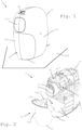
- FIGS 1 to 12 illustrate an exemplary embodiment of a beverage machine 1 according to the invention and parts of such machine 1.
- Machine 1 is configured for preparing a beverage, such as a beverage prepared from an ingredient selected from at least one of: coffee; tea; chocolate; cocoa; milk; soup; and baby food.
- Machine 1 has a body 1' comprising a seat 4 and a beverage processing line 1",1′′′ extending from a liquid inlet 1" to a beverage dispenser 1′′′. See Figs 1 to 3 .
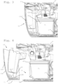
- Liquid inlet 1" may be connected to a source of liquid, e.g. water, such as a machine tank 2 and/or an external liquid supply line. See Figs 3 and 4 .
- Liquid line 1",1′′′ can extend via a pump 3 and/or a thermal conditioner 3' such as a heater and/or a cooler. See Figs 2 and 3 .
- Machine 1 has a service unit 10 that is removably received in or on seat 4.
- Unit 10 comprises a foot part 11 and a recipient part 12 removably received in or on foot part 11 so as to be supported thereby.
- Foot part 11 has a bottom face 11' configured to rest on an external horizontal support surface 100 when service unit 10 is removed from the seat 4. See Figs 1 to 4 .
- Seat 4 may be delimited by a platform 4a for supporting service unit 10 in or on seat 4 and/or for guiding service unit 10 into or onto the seat 4. See Figs 2 and 4 .
- the recipient part can be configured to store un-used beverage ingredient and/or beverage liquid and/or cleaning fluid, to be supplied to the beverage processing line.
- Recipient part 12 can be configured to store used beverage ingredient and/or waste beverage liquid and/or used cleaning fluid, collected from the beverage processing line 1",1′′′. See Fig. 3 .
- recipient part 12 When recipient part 12 is received in or on foot part 11, recipient part 12 is movable relative to foot part 11 from a first stable position when the service unit 10 rests on external horizontal support surface 100 to a second stable position when service unit 10 is received in or on seat 4, and vice versa. It being understood that the first and second stable positions are different. See Figs 1 to 4 .
- Recipient part 12 can be moved into its first stable position by gravity force onto recipient part 12 and/or a biasing element. See Figs 5 and 6 .
- Recipient part 12 may be moved into its second stable position by mechanical resistance of seat 4 when recipient part 12 is urged against a body part 4" delimiting seat 4 while service unit 10 is being moved into or onto seat 4. See Figs 3 and 4 .
- a first vertical projection G1 of a centre of gravity G of service unit 10 on a plane P containing boundary 11" of bottom face 11' can be contained within boundary 11". See Fig. 6 .
- a second vertical projection G2 of centre of gravity G of service unit 10 on plane P can be located off boundary 11" of bottom face 11' or closer to boundary 11" than first vertical projection G1. See Fig. 5 .
- Recipient part 12 and foot part 11 may be articulated and/or translationally connected, when recipient part 12 is received in or on foot part 11. See Figs 3 to 6 .
- Recipient part 12 may be pivotally movable relative to foot part 11 when recipient part 12 is received in or on foot part 11.
- Recipient part 12 can be fastened to foot part 11 when recipient part 12 is received in or on foot part 11.
- recipient part 12 is fastened to foot part 11 by at least one of a bias, spring, hook, lock and friction mechanism. See Figs 5 to 12 .
- Recipient part 12 can be fastened to foot part 11 by a dismantlable bearing arrangement that guides recipient part 12 and foot part 11 for their relative movement. See Figs 5 to 8 as well as 11 and 12.
- Foot part 11 may include one or more protrusions 11a that are urged into corresponding recesses 12a of recipient part 12 and/or vice versa. See Figs 11 and 12 .
- protrusion 11a and corresponding recess 12a may be arranged to be relatively movable by translation and/or pivoting to relatively move foot part 11 and recipient part 12. See Figs 5 to 8 as well as 11 and 12.
- Such a protrusion 11a can be formed as a pin and the corresponding recess can be formed as a hole 12a, e.g. a blind hole, or a channel or groove. See Figs 11 and 12 .
- Recipient part 12 may have a recipient bottom 12b that rests on foot part 11 in the first stable position and that is at least partly lifted away from foot part 11 in the second stable position.
- Recipient bottom 12b may be tilted upwards and/or translated in the second stable position. See Figs 3 to 6 .
- Recipient part 12 may contain a removable auxiliary recipient 12c. See Figs. 2 to 10 .
- Auxiliary recipient 12c may be configured for collecting solid material and may have a bottom 12c' with one or more through openings for allowing the passage of liquid material from auxiliary recipient 12c to underneath auxiliary recipient 12c to be collected on a recipient bottom 12b of recipient part 12. See Fig. 3 .
- Auxiliary recipient 12c can be fitted with a handle 12c" for seizing auxiliary recipient 12c to remove auxiliary recipient 12c from recipient part 12. See Figs 5 to 10 .
- Service unit 10 can be releasably fastened in seat 4, such as fastened by at least one of a bias, spring, hook, lock and friction mechanism, e.g. by a resilient and/or magnetically configured connection arrangement 4'12c''.
- Service unit 10 may include a handle 12c'' that forms a service unit connector 12c'' of connection arrangement 4',12c". See Figs 3 and 4 .
- Foot part 11 may have an upright wall portion 11b that forms part of an outside machine housing 1a', such as an upright wall portion 11b covering seat 4, when service unit 10 is received in or on seat 4.
- Upright wall portion 11b may delimit a cavity 11b', such as a cavity between an inner upright wall portion 11b" and an outer upright wall portion 11b′′′.
- Cavity 11b' can contain an electric device 11b IV , e.g. a signal or light emitter and/or a signal or light sensor, which electric device 11b IV has a wired or wireless connection 11b v to a control unit 5 of body 1'. See Figs 2 to 12 .
- Machine 1 may include machine tank 2. See Figs 2 to 4 .
- Machine tank 2 may be removably received in or on seat 4 when connected to liquid inlet 1". For instance, tank 2 is insertable into or onto seat 4 and removable from seat 4 providing service unit 10 has been removed from seat 4. See Figs 2 to 4 .
- Machine tank 2 can be fitted with a lid 2' movable or removable for filling machine tank 2 with liquid. See Fig. 3 .
- Machine tank 2 may be provided with an outlet connector that is connectible to liquid inlet 1".
- the outlet connector and liquid inlet 1'' have a generally horizontal connection and disconnection direction. See Fig. 3 .
- Liquid dispenser 1′′′ may include a beverage outlet 1 iv .
- Beverage outlet 1 iv can be fixed to a dispensing head.
- Liquid dispenser 1′′′ can have a dispensing head that can move inwards into body 1' for storage and outwards out of body 1' for dispensing. Dispensing head may bear a beverage outlet 1 iv .
- Liquid dispenser 1′′′ can comprise a control unit 5 for controlling beverage processing line 1",1′′′.
- Liquid dispenser 1′′′ may include a user-interface 50 connected to a control unit 5 for controlling beverage processing line 1",1′′′.
- Beverage processing line 1",1′′′ can comprise a beverage mixing unit 6 in fluid communication with liquid inlet 1" and beverage dispenser 1′′′.
- beverage mixing unit 6 has a mixing cavity and an ingredient inlet channel 6' for handling an ingredient to be mixed with liquid. See Figs 1 and 2 .
- Ingredient inlet channel 6' can have an ingredient gate 6" that has a configuration that allows an ingredient to travel to the mixing cavity and a configuration that prevents an ingredient to travel to the mixing cavity. See Fig. 2 .
- Ingredient inlet channel 6' and a mixing cavity can be configured for handling a preportioned ingredient supplied within an ingredient capsule.
Landscapes
- Engineering & Computer Science (AREA)
- Food Science & Technology (AREA)
- Apparatus For Making Beverages (AREA)
- Devices For Dispensing Beverages (AREA)
Claims (15)
- Machine (1) permettant de préparer une boisson, telle qu'une boisson préparée à partir d'un ingrédient choisi parmi au moins l'un parmi du café et du thé et du chocolat et du cacao et du lait et de la soupe et des aliments pour bébé, comprenant :- un corps (1') comprenant un siège (4) et un conduit de traitement de boisson (1 ", 1‴) s'étendant d'une entrée de liquide (1") jusqu'à un distributeur de boisson (1‴), l'entrée de liquide (1") étant éventuellement reliée à une source de liquide, e.g. de l'eau, telle qu'un réservoir de machine (2) et/ou un conduit d'alimentation de liquide externe, le conduit de liquide (1", 1‴) s'étendant facultativement par l'intermédiaire d'une pompe (3) et/ou d'un conditionneur thermique (3') tel qu'un élément chauffant et/ou un refroidisseur ; et- une unité de service (10) qui est reçue de manière amovible dans ou sur le siège (4) et qui comprend une partie de pied (11) et une partie de récipient (12) reçue de manière amovible dans ou sur la partie de pied (11) de façon à être supportée de ce fait, la partie de pied (11) ayant un côté inférieur (11') conçu pour reposer sur une surface de support horizontale externe (100) lorsque l'unité de service (10) est retirée du siège (4),facultativement le siège (4) étant délimité par une plate-forme (4a) permettant de supporter l'unité de service (10) dans ou sur le siège (4) et/ou permettant de guider l'unité de service (10) dans ou sur le siège (4),la partie de récipient (12) étant conçue pour stocker :- un ingrédient de boisson et/ou un liquide de boisson et/ou un fluide de nettoyage non utilisés, à fournir au conduit de traitement de boisson (1", 1‴) ; et/ou- un ingrédient de boisson et/ou un liquide de boisson et/ou un fluide de nettoyage utilisés, recueillis à partir de la ligne de traitement de boisson (1", 1‴),caractérisée en ce que, lorsque la partie de récipient (12) est reçue dans ou sur la partie de pied (11), la partie de récipient (12) est mobile par rapport à la partie de pied (11) d'une première position stable lorsque l'unité de service (10) repose sur ladite surface de support horizontale externe (100) jusqu'à une seconde position stable lorsque l'unité de service (10) est reçue dans ou sur le siège (4), et vice versa, les première et seconde positions stables étant différentes.
- Machine selon l'une quelconque revendication précédente, dans laquelle la partie de récipient (12) est déplacée dans :- sa première position stable par une force de gravité sur la partie de récipient (12) et/ou un élément de sollicitation ; et/ou- sa seconde position stable par résistance mécanique du siège (4) lorsque la partie de récipient (12) est poussée contre une partie de corps (4") délimitant le siège (4) tandis que l'unité de service (10) est déplacée dans ou sur le siège (4).
- Machine selon la revendication 1 ou 2, dans laquelle, lorsque la partie de pied (11) de l'unité de service (10) repose sur ladite surface de support horizontale externe (100) et que la partie de récipient (12) est reçue dans ou sur la partie de pied (11), une première projection verticale (G1) d'un centre de gravité (G) de l'unité de service (10) sur un plan (P) contenant la limite (11") du côté inférieur (11') est contenue au sein de ladite limite (11").
- Machine selon la revendication 3, dans laquelle, lorsque l'unité de service (10) est reçue dans ou sur le siège (4) et la partie de récipient (12) est reçue dans ou sur la partie de pied (11) et le corps (1') repose sur ladite surface de support horizontale externe (100), une seconde projection verticale (G2) du centre de gravité (G) de l'unité de service (10) sur le plan (P) est située hors de la limite (11') du côté inférieur (11") ou plus proche de la limite (11") que de la première projection verticale (G1).
- Machine selon l'une quelconque revendication précédente, dans laquelle la partie de récipient (12) et la partie de pied (11) sont articulées et/ou reliées en translation, lorsque la partie de récipient (12) est reçue dans ou sur la partie de pied (11).
- Machine selon l'une quelconque revendication précédente, dans laquelle la partie de récipient (12) est mobile en relation pivotante par rapport à la partie de pied (11) lorsque la partie de récipient (12) est reçue dans ou sur la partie de pied (11).
- Machine selon l'une quelconque revendication précédente, dans laquelle la partie de récipient (12) est fixée à la partie de pied (11) lorsque la partie de récipient (12) est reçue dans ou sur la partie de pied (11), facultativement la partie de récipient (12) étant fixée à la partie de pied (11) par au moins l'un parmi un mécanisme de sollicitation, de ressort, de crochet, de verrouillage et de friction.
- Machine selon la revendication 7, dans laquelle la partie de récipient (12) est fixée à la partie de pied (11) par un agencement de palier démontable qui guide la partie de récipient (12) et la partie de pied (11) pour leur mouvement relatif.
- Machine selon la revendication 7 ou 8, dans laquelle la partie de pied (11) comprend une ou plusieurs saillies (11a) qui sont poussées dans des évidements correspondants (12a) de la partie de récipient (12) et/ou dans laquelle le récipient comprend une ou plusieurs saillies qui sont poussées dans des évidements correspondants de la partie de pied, et dans laquelle de tels saillie et évidement correspondant sont relativement mobiles par translation et/ou relation pivotante pour déplacer relativement la partie de pied (11) et la partie de récipient (12), facultativement une telle saillie (11a) étant formée en guise de broche et l'évidement correspondant étant formé en guise de trou (12a), e.g. un trou borgne, ou un canal ou une rainure.
- Machine selon l'une quelconque revendication précédente, dans laquelle la partie de récipient (12) a un fond de récipient (12b) qui repose sur la partie de pied (11) dans la première position stable et qui est au moins partiellement soulevée à l'écart de la partie de pied (11) dans la seconde position stable, le fond de récipient (12b) étant par exemple incliné vers le haut et/ou déplacé en translation dans la seconde position stable.
- Machine selon l'une quelconque revendication précédente, dans laquelle la partie de récipient (12) contient un récipient auxiliaire (12c) amovible, tel qu'un récipient auxiliaire (12c) qui est :- conçu pour collecter un matériau solide et qui a un fond (12c') avec une ou plusieurs ouvertures traversantes pour permettre le passage de matériau liquide du récipient auxiliaire (12c) jusqu'au-dessous du récipient auxiliaire (12c) à collecter sur un fond de récipient
(12b) de la partie de récipient (12) ; et/ou- équipé d'une poignée (12c") permettant de saisir le récipient auxiliaire (12c) pour retirer le récipient auxiliaire (12c) de la partie de récipient (12). - Machine selon l'une quelconque revendication précédente, dans laquelle l'unité de service (10) est fixée de manière libérable dans le siège (4), telle que fixée par au moins l'un parmi un mécanisme de sollicitation, de ressort, de crochet, de verrouillage et de friction, e.g. par un agencement de liaison élastique et/ou conçu magnétiquement (4'120"), facultativement l'unité de service (10) comprenant une poignée (12c") qui forme un dispositif de liaison d'unité de service (12c") de l'agencement de liaison (4', 12c").
- Machine selon l'une quelconque revendication précédente, dans laquelle la partie de pied (11) comprend une partie de paroi verticale (11b) qui forme une partie d'un boîtier de machine externe (1a'), telle qu'une partie de paroi verticale (11b) couvrant le siège (4), lorsque l'unité de service (10) est reçue dans ou sur le siège (4), facultativement la partie de paroi verticale (11b) délimitant une cavité (11b'), telle qu'une cavité entre une partie de paroi verticale interne (11b") et une partie de paroi verticale externe (11b‴), la cavité (11b') contenant par exemple un dispositif électrique (11bIV), e.g. un émetteur de signal ou de lumière et/ou un capteur de signal ou de lumière, lequel dispositif électrique (11bIV) a une connexion filaire ou sans fil (11bv) à une unité de commande (5) du corps (1').
- Machine selon l'une quelconque revendication précédente, qui comprend ledit réservoir de machine (2) et dans laquelle le réservoir de machine (2) est au moins l'un parmi :- reçu de manière amovible dans ou sur le siège (4) lorsqu'il est relié à l'entrée de liquide (1"), facultativement le réservoir de machine (2) étant insérable dans ou sur le siège (4) et amovible du siège (4) à condition que l'unité de service (10) ait été retirée du siège (4) ;- équipé avec un couvercle (2') mobile ou amovible pour remplir le réservoir de machine (2) avec du liquide ; et- pourvu d'un dispositif de liaison de sortie qui peut être relié à l'entrée de liquide (1"), le dispositif de liaison de sortie et l'entrée de liquide (1") ayant par exemple une direction de liaison et de séparation généralement horizontale.
- Machine selon l'une quelconque revendication précédente, dans laquelle :- le distributeur de liquide (1‴) comprend au moins l'un parmi :- une sortie de boisson (1iv), telle qu'une sortie de boisson (1iv) fixée à une tête de distribution ;- une tête de distribution qui peut se déplacer vers l'intérieur dans le corps (1') pour le stockage et vers l'extérieur du corps (1') pour la distribution, telle qu'une tête de distribution portant une sortie de boisson (1iv) ;- une unité de commande (5) permettant de commander le conduit de traitement de boisson (1", 1‴) ; et- une interface utilisateur (50) connectée à une unité de commande (5) permettant de commander le conduit de traitement de boisson (1", 1‴)
et/ou- le conduit de traitement de boisson (1", 1‴) comprend une unité de mélange de boisson (6) en communication fluidique avec l'entrée de liquide (1") et le distributeur de boisson (1‴), facultativement l'unité de mélange de boisson (6) comprenant une cavité de mélange et un canal d'entrée d'ingrédient (6') permettant de manipuler un ingrédient à mélanger avec un liquide, tel que :- un canal d'entrée d'ingrédient (6') ayant une vanne d'ingrédient (6') qui a une configuration qui permet à un ingrédient de circuler jusqu'à la cavité de mélange et une configuration qui empêche un ingrédient de circuler jusqu'à la cavité de mélange ; et/ou- un canal d'entrée d'ingrédient (6') et une cavité de mélange conçue pour manipuler un ingrédient prédosé fourni au sein d'une capsule d'ingrédient.
Applications Claiming Priority (2)
| Application Number | Priority Date | Filing Date | Title |
|---|---|---|---|
| EP18197094 | 2018-09-27 | ||
| PCT/EP2019/076137 WO2020064982A1 (fr) | 2018-09-27 | 2019-09-27 | Unité de service adaptative d'une machine à boisson |
Publications (2)
| Publication Number | Publication Date |
|---|---|
| EP3855988A1 EP3855988A1 (fr) | 2021-08-04 |
| EP3855988B1 true EP3855988B1 (fr) | 2024-07-24 |
Family
ID=63685827
Family Applications (1)
| Application Number | Title | Priority Date | Filing Date |
|---|---|---|---|
| EP19773849.5A Active EP3855988B1 (fr) | 2018-09-27 | 2019-09-27 | Unité de service adaptative d'une machine à boissons |
Country Status (7)
| Country | Link |
|---|---|
| US (1) | US12390044B2 (fr) |
| EP (1) | EP3855988B1 (fr) |
| JP (1) | JP7382398B2 (fr) |
| CN (1) | CN112689466B (fr) |
| AU (1) | AU2019348522B2 (fr) |
| CA (1) | CA3113758A1 (fr) |
| WO (1) | WO2020064982A1 (fr) |
Families Citing this family (1)
| Publication number | Priority date | Publication date | Assignee | Title |
|---|---|---|---|---|
| EP3928665A1 (fr) * | 2020-06-22 | 2021-12-29 | Koninklijke Philips N.V. | Distributeur de boissons doté d'un bac de déchets |
Family Cites Families (108)
| Publication number | Priority date | Publication date | Assignee | Title |
|---|---|---|---|---|
| US3613566A (en) | 1969-10-20 | 1971-10-19 | Lloyd P Shapleigh Jr | Refuse compactor |
| JPS496239Y1 (fr) * | 1972-06-26 | 1974-02-13 | ||
| CH605293A5 (fr) | 1976-12-17 | 1978-09-29 | Nestle Sa | |
| TW199884B (fr) | 1991-05-08 | 1993-02-11 | Sociere Des Produits Nestle S A | |
| US5161455A (en) | 1991-05-15 | 1992-11-10 | Bunn-O-Matic Corporation | Combination coffee and tea brewer |
| IT1252633B (it) | 1991-12-05 | 1995-06-19 | Gianmauro Zani | Macchina da caffe' compatta per caffe' espresso e per caffe' a caduta di acqua calda per filtrazione altrimenti detto caffe' all'americana. |
| US5353692A (en) | 1993-09-29 | 1994-10-11 | Unidynamics Corporation | Hot beverage brewing apparatus |
| ATE282982T1 (de) | 1999-08-31 | 2004-12-15 | Nestle Sa | Vorrichtung zum extrahieren einer substanz für die zubereitung eines getränkes |
| US6459854B1 (en) | 2000-01-24 | 2002-10-01 | Nestec S.A. | Process and module for heating liquid |
| FR2806606B1 (fr) | 2000-03-24 | 2002-10-25 | Moulinex Sa | Machine a cafe electrique avec reservoir d'eau pivotant |
| EP1208782B1 (fr) | 2000-11-28 | 2004-08-25 | Societe Des Produits Nestle S.A. | Dispositif de percolation |
| MXPA04006848A (es) | 2002-01-16 | 2004-12-08 | Nestle Sa | Capsula cerrada con medio de abertura. |
| DE60227248D1 (de) | 2002-07-12 | 2008-08-07 | Nestec Sa | Vorrichtung zum Erhitzen einer Flüssigkeit |
| GB2397503B (en) | 2003-01-24 | 2005-03-02 | Kraft Foods R & D Inc | Machine for the preparation of beverages |
| EP1495702A1 (fr) | 2003-07-10 | 2005-01-12 | Nestec S.A. | Dispositif pour l'extraction d'une capsule |
| JP4695091B2 (ja) | 2003-11-22 | 2011-06-08 | ネステク ソシエテ アノニム | 飲料又は類似した製品を調合するための加圧気体供給を備える移動式又は携帯型装置 |
| US7165488B2 (en) | 2003-12-12 | 2007-01-23 | Keurig, Incorporated | Brew chamber for a single serve beverage brewer |
| EP1634520A1 (fr) | 2004-09-13 | 2006-03-15 | Nestec S.A. | Dispositif de chauffage d'un liquide et procede pour chauffer un liquide |
| ES2360218T3 (es) | 2004-11-11 | 2011-06-01 | Nestec S.A. | Cabezal de mezclado auto-limpiable para producir una mezcla a base de leche y máquinas de producción de bebidas comprendiendo dicho cabezal de mezclado. |
| ES2306427T3 (es) | 2005-03-29 | 2008-11-01 | Nestec S.A. | Maquina autonoma para distribuir bebidas. |
| DE602005007475D1 (de) | 2005-06-07 | 2008-07-24 | Nestec Sa | Getränkemaschine mit Auffangwanne für Behälter unterschiedlicher Höhe |
| PL1767129T3 (pl) | 2005-09-27 | 2009-04-30 | Nestec Sa | Moduł ekstrakcyjny dla urządzenia do wytwarzania napoju na bazie kapsułki |
| DE202006002678U1 (de) | 2006-02-17 | 2006-04-20 | Eugster/Frismag Ag | Kaffeemaschine zur Zubereitung eines Kaffeegetränks mittels abgepackter, vorportionierter Kaffeepouches |
| FR2898028B1 (fr) | 2006-03-01 | 2008-05-16 | Seb Sa | Machine a infuser comprenant un dispositif d'ejection du produit infuse |
| US7513192B2 (en) | 2006-03-23 | 2009-04-07 | Keurig, Incorporated | Beverage forming device with opening/closing mechanism for a beverage cartridge receiver |
| PT1859713E (pt) | 2006-05-24 | 2009-09-24 | Nestec Sa | Dispositivo de infusão para cápsula com mecanismo de fecho de relação de transmissão variável |
| EP1864598B1 (fr) | 2006-06-09 | 2011-02-16 | Nestec S.A. | Système modulaire de production de boissons comprenant une station d'accueil |
| EP2189088B1 (fr) | 2006-06-16 | 2013-05-15 | Nestec S.A. | Dispositif de distribution de boissons avec système de support et de récupération de gouttes pour récipients de différentes tailles |
| PT1878368E (pt) | 2006-07-11 | 2009-07-28 | Nestec Sa | Máquina de produção de bebidas com bloco funcional e base de apoio |
| DE602007012564D1 (de) | 2006-09-26 | 2011-03-31 | Nestec Sa | Extraktionssystem für die zubereitung eines getränks aus einer patrone |
| EP1992263B2 (fr) | 2007-05-16 | 2016-10-12 | Nestec S.A. | Module de fabrication de boissons et procédé de fonctionnement du module de fabrication de boissons |
| ITFI20070184A1 (it) | 2007-08-02 | 2009-02-03 | Saeco Ipr Ltd | "supporto a doppio piano di appoggio per tazze e altri contenitori in macchine per la produzione di bevande" |
| WO2009043851A2 (fr) | 2007-10-04 | 2009-04-09 | Nestec S.A. | Dispositif de chauffage intégré pour un dispositif de préparation de boisson |
| CL2008002963A1 (es) | 2007-10-04 | 2010-01-22 | Nestec Sa | Dispositivo calentador para una maquina para la preparacion de alimento liquido o bebida, que comprende una unidad termica con una masa metalica, a traves de la cual circula el liquido, y acumula calor y lo suministra al liquido, y tiene uno o mas componentes electricos asegurados en forma rigida a la unidad termica; y maquina. |
| AU2008306060C1 (en) | 2007-10-04 | 2015-08-27 | Société des Produits Nestlé S.A. | Beverage brewing unit |
| EP2227121B1 (fr) | 2007-12-12 | 2011-04-13 | Nestec S.A. | Réceptacle de capsules ou de gobelets usagé(e)s pour machine à préparer un aliment liquide ou une boisson |
| EP2070454B1 (fr) | 2007-12-12 | 2015-07-15 | Nestec S.A. | Fabrication modulaire de machines de production de boissons |
| EP2278900B1 (fr) | 2008-04-22 | 2016-04-27 | Nestec S.A. | Assemblage modulaire d' une maschine à préparer der boissons |
| PT2276380E (pt) | 2008-05-07 | 2013-08-23 | Nestec Sa | Receptáculo para cápsulas utilizadas para dispositivos de bebidas |
| PT2296515E (pt) | 2008-05-28 | 2012-08-24 | Nestec Sa | Bomba para dispositivos de preparação de bebidas líquidas |
| DK2317898T3 (da) | 2008-07-14 | 2012-10-15 | Nestec Sa | Vandcirkulationssystem til en driktilberedningsindretning |
| JP5608647B2 (ja) | 2008-08-08 | 2014-10-15 | ネステク ソシエテ アノニム | 持ち運びハンドルおよび設定変更可能な外観ならびに副次的機能を伴う飲料装置 |
| CA2736927A1 (fr) | 2008-10-03 | 2010-04-08 | Nestec S.A. | Interface conviviale pour une machine a boissons |
| EP2208450A1 (fr) * | 2009-01-14 | 2010-07-21 | Nestec S.A. | Système modulaire avec module autonome de petite empreinte |
| EP2228633B1 (fr) | 2009-03-10 | 2017-07-05 | Nestec S.A. | Détecteur optique de niveau pour une machine à boissons |
| RU2534915C2 (ru) | 2009-03-23 | 2014-12-10 | Нестек С.А. | Крепление насоса в аппарате для приготовления напитка |
| EP2427085B1 (fr) | 2009-05-06 | 2016-09-21 | Nestec S.A. | Methode de production de machines de boisson avec entretien simplifié |
| EP2445380A1 (fr) | 2009-06-24 | 2012-05-02 | Nestec S.A. | Fusible thermique pour pompe de machine de boissons |
| CN102460087B (zh) | 2009-06-25 | 2016-04-13 | 雀巢产品技术援助有限公司 | 用于饮料机器的流量计材料 |
| EP2446232B1 (fr) | 2009-06-25 | 2017-08-23 | Nestec S.A. | Structure de débitmètre pour distributeur de boissons |
| WO2011042400A2 (fr) | 2009-10-05 | 2011-04-14 | Nestec S.A. | Dispositif d'extraction de cartouche |
| PT2485629E (pt) | 2009-10-05 | 2014-01-21 | Nestec Sa | Dispositivo de extracção ergonómica de cápsulas |
| AU2010326841B2 (en) | 2009-12-01 | 2014-12-04 | Société des Produits Nestlé S.A. | Flowmeter assembly for a beverage machine |
| WO2011067181A1 (fr) | 2009-12-01 | 2011-06-09 | Nestec S.A. | Raccordement d'un débitmètre et d'une carte de circuit imprimé dans une machine à boissons |
| WO2011083103A2 (fr) | 2010-01-06 | 2011-07-14 | Nestec S.A. | Réservoir d'eau anti-vibrations d'une machine à boisson |
| WO2011086087A1 (fr) * | 2010-01-15 | 2011-07-21 | Nestec S.A. | Unité de service ergonomique pour machines de préparation de boisson |
| JP2013517026A (ja) | 2010-01-15 | 2013-05-16 | ネステク ソシエテ アノニム | 人間工学的原材料ホルダとサービスユニットとの協調 |
| EP2525693B2 (fr) | 2010-01-21 | 2018-01-10 | Nestec S.A. | Machine à boissons comprenant un réservoir amovible d'approvisionnement en liquide |
| EP2353469A1 (fr) | 2010-02-03 | 2011-08-10 | Nestec S.A. | Machine de préparation de boissons pour boissons de grande taille |
| US20120328456A1 (en) | 2010-03-05 | 2012-12-27 | Nestec S.A. | Reduction of pump nuisance |
| AU2011254528B2 (en) | 2010-05-21 | 2015-04-23 | Société des Produits Nestlé S.A. | Ergonomic dispenser interface |
| WO2011144723A1 (fr) | 2010-05-21 | 2011-11-24 | Nestec S.A. | Distributeur de boisson à gestion ergonomique de l'eau |
| PT2571404E (pt) | 2010-05-21 | 2014-05-06 | Nestec Sa | Manípulo ergonómico e interface de utilizador |
| EP2579754B1 (fr) | 2010-06-09 | 2016-01-06 | Nestec S.A. | Agencement de service ergonomique pour distributeur de boissons |
| AU2011267130B2 (en) | 2010-06-17 | 2015-11-19 | Société des Produits Nestlé S.A. | Fast heat-up of a thermal conditioning device e.g. for coffee machine |
| WO2012007313A1 (fr) | 2010-07-12 | 2012-01-19 | Nestec S.A. | Support de tasse sécurisé pour machine de préparation de boissons |
| MX365198B (es) | 2010-08-27 | 2019-05-27 | Nestec Sa | Unidad de infusion motorizada simple. |
| CA2810451A1 (fr) | 2010-09-07 | 2012-03-15 | Nestec S.A. | Poignee ergonomique a interface utilisateur |
| EP2430954A1 (fr) * | 2010-09-21 | 2012-03-21 | Nestec S.A. | Distributeur produisant des boissons à partir de poudre |
| JP2013544568A (ja) | 2010-10-27 | 2013-12-19 | ネステク ソシエテ アノニム | 複数の異なる空間環境のための飲料マシン |
| BR112013010542A2 (pt) | 2010-10-27 | 2018-06-19 | Nestec Sa | máquina para bebida com uma saída acessível (conveniente) |
| EP2645914B1 (fr) | 2010-12-01 | 2016-07-13 | Nestec S.A. | Machine de préparation de boisson ayant collecteur de gouttes |
| CN103442624B (zh) | 2011-03-14 | 2017-04-26 | 雀巢产品技术援助有限公司 | 自动饮料机 |
| RU2013147192A (ru) | 2011-03-23 | 2015-04-27 | Нестек С.А. | Аппарат для приготовления напитков с крышкой для входа для ингредиента |
| PT2747611T (pt) | 2011-08-25 | 2017-12-26 | Nestec Sa | Câmara de cartucho de sistema de extração |
| KR101145137B1 (ko) * | 2011-09-14 | 2012-05-14 | 경북대학교 산학협력단 | 커피머신 |
| CA2859057C (fr) | 2011-12-30 | 2019-09-03 | Nestec S.A. | Machine a preparer des boissons a systemes multiples |
| ES2573543T3 (es) * | 2012-01-13 | 2016-06-08 | Nestec S.A. | Máquina de bebidas para tazas altas y cortas |
| WO2013104643A1 (fr) | 2012-01-13 | 2013-07-18 | Nestec S.A. | Machine à boisson dotée d'un module amovible |
| EP2658421B1 (fr) | 2012-02-28 | 2016-05-11 | Nestec S.A. | Unité de brassage motorisé contrôlé par capsule |
| EP2633789A1 (fr) | 2012-02-28 | 2013-09-04 | Nestec S.A. | Machine de préparation de boissons avec gestion de résidus liquids |
| US8808778B2 (en) * | 2012-06-05 | 2014-08-19 | Louis Dakis | Method of using a multi-layer brewing cup |
| US9943187B2 (en) | 2012-06-15 | 2018-04-17 | Nestec S.A. | Beverage machine with vibration inhibitor |
| AU2013329854B2 (en) | 2012-10-09 | 2017-11-16 | Nestec S.A. | Beverage machine |
| US10092130B2 (en) | 2012-11-12 | 2018-10-09 | Nestec S.A. | Opener for making large openings in capsules |
| EP2950689A2 (fr) | 2013-01-30 | 2015-12-09 | Indesit Company S.p.A. | Machine à café |
| ITMI20130345A1 (it) | 2013-03-07 | 2014-09-08 | Illycaffe Spa | Macchina per la preparazione di bevande. |
| US8893922B2 (en) * | 2013-03-15 | 2014-11-25 | Feniks, Inc. | Automated coffee vending kiosk and associated systems |
| RU2015145283A (ru) | 2013-03-22 | 2017-04-26 | Нестек С.А. | Капсула с кодом и автоматическая система для приготовления напитков |
| CN105813509A (zh) | 2013-12-11 | 2016-07-27 | 雀巢产品技术援助有限公司 | 带有可枢转式胶囊出入口的饮料机 |
| EP3166457B1 (fr) | 2014-07-09 | 2019-10-09 | Société des Produits Nestlé S.A. | Dispositif de raccordement d'une machine à boissons à un réseau de distribution avec surveillance sécurisée |
| ES2875040T3 (es) | 2014-07-09 | 2021-11-08 | Nestle Sa | Acoplamiento de un dispositivo para conectar una máquina de bebidas a una red de distribución |
| ES2699086T3 (es) | 2014-07-09 | 2019-02-07 | Nestec Sa | Accesorio para suministrar automáticamente a una máquina de bebidas un líquido a partir de una red de distribución |
| ES2828253T3 (es) | 2014-07-09 | 2021-05-25 | Nestle Sa | Dispositivo para conectar una máquina de bebidas a una red de distribución con interrupción segura de flujo |
| WO2016096707A1 (fr) | 2014-12-18 | 2016-06-23 | Nestec S.A. | Machine de boisson comprenant un support de gobelet à auto-positionnement |
| WO2016096706A1 (fr) | 2014-12-18 | 2016-06-23 | Nestec S.A. | Plate-forme de support de gobelet amovible sur réceptacle de collecteur |
| EP3232875B1 (fr) | 2014-12-18 | 2024-05-29 | Société des Produits Nestlé S.A. | Machine à boissons avec support de verre connectable de manière coulissante |
| WO2016156367A1 (fr) * | 2015-04-02 | 2016-10-06 | Nestec S.A. | Porte-gobelet coulissant |
| US11116355B2 (en) * | 2015-09-04 | 2021-09-14 | Societe Des Produits Nestle S.A. | Beverage machine with an ergonomic user-interface |
| RU2721090C2 (ru) | 2015-09-04 | 2020-05-15 | Сосьете Де Продюи Нестле С.А. | Устройство для приготовления напитка с эргономичным выходным каналом |
| AU2016353456B2 (en) | 2015-11-11 | 2022-02-24 | Société des Produits Nestlé S.A. | Easy connection of a liquid tank to a beverage machine |
| CA3010682A1 (fr) | 2016-01-08 | 2017-07-13 | Nestec S.A. | Machine a boissons comprenant un element de stockage d'eau ergonomique |
| CN109310230B (zh) | 2016-06-30 | 2022-06-21 | 雀巢产品有限公司 | 具有受控泵的饮料制备机器 |
| AU201711149S (en) * | 2016-09-06 | 2017-03-15 | SOCIAƒA©TAƒA© DES PRODUITS NESTLAƒA© S A | A coffee machine |
| ES2893852T3 (es) | 2016-09-09 | 2022-02-10 | Nestle Sa | Máquina de bebidas con manejo ergonómico |
| AU201711683S (en) * | 2016-09-30 | 2017-04-07 | SOCIAƒA©TAƒA© DES PRODUITS NESTLAƒA© S A | A coffee machine |
| AU2017343599B2 (en) | 2016-10-11 | 2023-02-02 | Société des Produits Nestlé S.A. | Liquid dispensing machine with drop stop |
| WO2018069268A1 (fr) | 2016-10-11 | 2018-04-19 | Nestec Sa | Machine de distribution de liquide à régulateur de vitesse |
-
2019
- 2019-09-27 JP JP2021516495A patent/JP7382398B2/ja active Active
- 2019-09-27 US US17/280,287 patent/US12390044B2/en active Active
- 2019-09-27 AU AU2019348522A patent/AU2019348522B2/en active Active
- 2019-09-27 CA CA3113758A patent/CA3113758A1/fr active Pending
- 2019-09-27 WO PCT/EP2019/076137 patent/WO2020064982A1/fr not_active Ceased
- 2019-09-27 CN CN201980058562.2A patent/CN112689466B/zh active Active
- 2019-09-27 EP EP19773849.5A patent/EP3855988B1/fr active Active
Also Published As
| Publication number | Publication date |
|---|---|
| WO2020064982A1 (fr) | 2020-04-02 |
| CA3113758A1 (fr) | 2020-04-02 |
| AU2019348522B2 (en) | 2025-01-23 |
| AU2019348522A1 (en) | 2021-02-18 |
| EP3855988A1 (fr) | 2021-08-04 |
| US12390044B2 (en) | 2025-08-19 |
| CN112689466B (zh) | 2023-09-05 |
| JP2022501124A (ja) | 2022-01-06 |
| JP7382398B2 (ja) | 2023-11-16 |
| CN112689466A (zh) | 2021-04-20 |
| US20220031112A1 (en) | 2022-02-03 |
Similar Documents
| Publication | Publication Date | Title |
|---|---|---|
| US10945552B2 (en) | Beverage machine with an ergonomic water storage | |
| EP3373779B1 (fr) | Connexion facile d'un réservoir de liquide pour une machine à boissons | |
| EP3629857B1 (fr) | Distributeur de boissons ayant une tête de distribution stockable | |
| US11344149B2 (en) | Beverage machine with ergonomic power switch | |
| EP3855986B1 (fr) | Machine pour boissons avec une distribution d'actionnement | |
| EP3855988B1 (fr) | Unité de service adaptative d'une machine à boissons | |
| EP3316743B1 (fr) | Intégration compacte d'un dispositif de manipulation de capsule | |
| US20240407586A1 (en) | Ergonomic beverage machine | |
| RU2801524C2 (ru) | Устройство для приготовления напитка | |
| EP3687347B1 (fr) | Distributeur de boissons doté d'un module amovible | |
| EP3399891B1 (fr) | Machine à boissons anti-infiltration | |
| EP3399892B1 (fr) | Machine à boissons conçue pour une station debout sécurisée | |
| CA3001089C (fr) | Raccordement facile d'un reservoir de liquide a une machine a boissons |
Legal Events
| Date | Code | Title | Description |
|---|---|---|---|
| STAA | Information on the status of an ep patent application or granted ep patent |
Free format text: STATUS: UNKNOWN |
|
| STAA | Information on the status of an ep patent application or granted ep patent |
Free format text: STATUS: THE INTERNATIONAL PUBLICATION HAS BEEN MADE |
|
| PUAI | Public reference made under article 153(3) epc to a published international application that has entered the european phase |
Free format text: ORIGINAL CODE: 0009012 |
|
| STAA | Information on the status of an ep patent application or granted ep patent |
Free format text: STATUS: REQUEST FOR EXAMINATION WAS MADE |
|
| 17P | Request for examination filed |
Effective date: 20210428 |
|
| AK | Designated contracting states |
Kind code of ref document: A1 Designated state(s): AL AT BE BG CH CY CZ DE DK EE ES FI FR GB GR HR HU IE IS IT LI LT LU LV MC MK MT NL NO PL PT RO RS SE SI SK SM TR |
|
| DAV | Request for validation of the european patent (deleted) | ||
| DAX | Request for extension of the european patent (deleted) | ||
| P01 | Opt-out of the competence of the unified patent court (upc) registered |
Effective date: 20230527 |
|
| GRAP | Despatch of communication of intention to grant a patent |
Free format text: ORIGINAL CODE: EPIDOSNIGR1 |
|
| STAA | Information on the status of an ep patent application or granted ep patent |
Free format text: STATUS: GRANT OF PATENT IS INTENDED |
|
| INTG | Intention to grant announced |
Effective date: 20240222 |
|
| GRAS | Grant fee paid |
Free format text: ORIGINAL CODE: EPIDOSNIGR3 |
|
| GRAA | (expected) grant |
Free format text: ORIGINAL CODE: 0009210 |
|
| STAA | Information on the status of an ep patent application or granted ep patent |
Free format text: STATUS: THE PATENT HAS BEEN GRANTED |
|
| AK | Designated contracting states |
Kind code of ref document: B1 Designated state(s): AL AT BE BG CH CY CZ DE DK EE ES FI FR GB GR HR HU IE IS IT LI LT LU LV MC MK MT NL NO PL PT RO RS SE SI SK SM TR |
|
| REG | Reference to a national code |
Ref country code: GB Ref legal event code: FG4D |
|
| REG | Reference to a national code |
Ref country code: CH Ref legal event code: EP |
|
| REG | Reference to a national code |
Ref country code: IE Ref legal event code: FG4D Ref country code: DE Ref legal event code: R096 Ref document number: 602019055760 Country of ref document: DE |
|
| REG | Reference to a national code |
Ref country code: NL Ref legal event code: FP |
|
| REG | Reference to a national code |
Ref country code: LT Ref legal event code: MG9D |
|
| PG25 | Lapsed in a contracting state [announced via postgrant information from national office to epo] |
Ref country code: PT Free format text: LAPSE BECAUSE OF FAILURE TO SUBMIT A TRANSLATION OF THE DESCRIPTION OR TO PAY THE FEE WITHIN THE PRESCRIBED TIME-LIMIT Effective date: 20241125 |
|
| REG | Reference to a national code |
Ref country code: AT Ref legal event code: MK05 Ref document number: 1705454 Country of ref document: AT Kind code of ref document: T Effective date: 20240724 |
|
| PG25 | Lapsed in a contracting state [announced via postgrant information from national office to epo] |
Ref country code: PT Free format text: LAPSE BECAUSE OF FAILURE TO SUBMIT A TRANSLATION OF THE DESCRIPTION OR TO PAY THE FEE WITHIN THE PRESCRIBED TIME-LIMIT Effective date: 20241125 |
|
| PG25 | Lapsed in a contracting state [announced via postgrant information from national office to epo] |
Ref country code: NO Free format text: LAPSE BECAUSE OF FAILURE TO SUBMIT A TRANSLATION OF THE DESCRIPTION OR TO PAY THE FEE WITHIN THE PRESCRIBED TIME-LIMIT Effective date: 20241024 |
|
| PG25 | Lapsed in a contracting state [announced via postgrant information from national office to epo] |
Ref country code: PL Free format text: LAPSE BECAUSE OF FAILURE TO SUBMIT A TRANSLATION OF THE DESCRIPTION OR TO PAY THE FEE WITHIN THE PRESCRIBED TIME-LIMIT Effective date: 20240724 Ref country code: GR Free format text: LAPSE BECAUSE OF FAILURE TO SUBMIT A TRANSLATION OF THE DESCRIPTION OR TO PAY THE FEE WITHIN THE PRESCRIBED TIME-LIMIT Effective date: 20241025 Ref country code: FI Free format text: LAPSE BECAUSE OF FAILURE TO SUBMIT A TRANSLATION OF THE DESCRIPTION OR TO PAY THE FEE WITHIN THE PRESCRIBED TIME-LIMIT Effective date: 20240724 |
|
| PG25 | Lapsed in a contracting state [announced via postgrant information from national office to epo] |
Ref country code: BG Free format text: LAPSE BECAUSE OF FAILURE TO SUBMIT A TRANSLATION OF THE DESCRIPTION OR TO PAY THE FEE WITHIN THE PRESCRIBED TIME-LIMIT Effective date: 20240724 |
|
| PG25 | Lapsed in a contracting state [announced via postgrant information from national office to epo] |
Ref country code: LV Free format text: LAPSE BECAUSE OF FAILURE TO SUBMIT A TRANSLATION OF THE DESCRIPTION OR TO PAY THE FEE WITHIN THE PRESCRIBED TIME-LIMIT Effective date: 20240724 |
|
| PG25 | Lapsed in a contracting state [announced via postgrant information from national office to epo] |
Ref country code: IS Free format text: LAPSE BECAUSE OF FAILURE TO SUBMIT A TRANSLATION OF THE DESCRIPTION OR TO PAY THE FEE WITHIN THE PRESCRIBED TIME-LIMIT Effective date: 20241124 Ref country code: AT Free format text: LAPSE BECAUSE OF FAILURE TO SUBMIT A TRANSLATION OF THE DESCRIPTION OR TO PAY THE FEE WITHIN THE PRESCRIBED TIME-LIMIT Effective date: 20240724 |
|
| PG25 | Lapsed in a contracting state [announced via postgrant information from national office to epo] |
Ref country code: HR Free format text: LAPSE BECAUSE OF FAILURE TO SUBMIT A TRANSLATION OF THE DESCRIPTION OR TO PAY THE FEE WITHIN THE PRESCRIBED TIME-LIMIT Effective date: 20240724 |
|
| PG25 | Lapsed in a contracting state [announced via postgrant information from national office to epo] |
Ref country code: RS Free format text: LAPSE BECAUSE OF FAILURE TO SUBMIT A TRANSLATION OF THE DESCRIPTION OR TO PAY THE FEE WITHIN THE PRESCRIBED TIME-LIMIT Effective date: 20241024 Ref country code: ES Free format text: LAPSE BECAUSE OF FAILURE TO SUBMIT A TRANSLATION OF THE DESCRIPTION OR TO PAY THE FEE WITHIN THE PRESCRIBED TIME-LIMIT Effective date: 20240724 |
|
| PG25 | Lapsed in a contracting state [announced via postgrant information from national office to epo] |
Ref country code: RS Free format text: LAPSE BECAUSE OF FAILURE TO SUBMIT A TRANSLATION OF THE DESCRIPTION OR TO PAY THE FEE WITHIN THE PRESCRIBED TIME-LIMIT Effective date: 20241024 Ref country code: PL Free format text: LAPSE BECAUSE OF FAILURE TO SUBMIT A TRANSLATION OF THE DESCRIPTION OR TO PAY THE FEE WITHIN THE PRESCRIBED TIME-LIMIT Effective date: 20240724 Ref country code: NO Free format text: LAPSE BECAUSE OF FAILURE TO SUBMIT A TRANSLATION OF THE DESCRIPTION OR TO PAY THE FEE WITHIN THE PRESCRIBED TIME-LIMIT Effective date: 20241024 Ref country code: LV Free format text: LAPSE BECAUSE OF FAILURE TO SUBMIT A TRANSLATION OF THE DESCRIPTION OR TO PAY THE FEE WITHIN THE PRESCRIBED TIME-LIMIT Effective date: 20240724 Ref country code: IS Free format text: LAPSE BECAUSE OF FAILURE TO SUBMIT A TRANSLATION OF THE DESCRIPTION OR TO PAY THE FEE WITHIN THE PRESCRIBED TIME-LIMIT Effective date: 20241124 Ref country code: HR Free format text: LAPSE BECAUSE OF FAILURE TO SUBMIT A TRANSLATION OF THE DESCRIPTION OR TO PAY THE FEE WITHIN THE PRESCRIBED TIME-LIMIT Effective date: 20240724 Ref country code: GR Free format text: LAPSE BECAUSE OF FAILURE TO SUBMIT A TRANSLATION OF THE DESCRIPTION OR TO PAY THE FEE WITHIN THE PRESCRIBED TIME-LIMIT Effective date: 20241025 Ref country code: FI Free format text: LAPSE BECAUSE OF FAILURE TO SUBMIT A TRANSLATION OF THE DESCRIPTION OR TO PAY THE FEE WITHIN THE PRESCRIBED TIME-LIMIT Effective date: 20240724 Ref country code: ES Free format text: LAPSE BECAUSE OF FAILURE TO SUBMIT A TRANSLATION OF THE DESCRIPTION OR TO PAY THE FEE WITHIN THE PRESCRIBED TIME-LIMIT Effective date: 20240724 Ref country code: BG Free format text: LAPSE BECAUSE OF FAILURE TO SUBMIT A TRANSLATION OF THE DESCRIPTION OR TO PAY THE FEE WITHIN THE PRESCRIBED TIME-LIMIT Effective date: 20240724 Ref country code: AT Free format text: LAPSE BECAUSE OF FAILURE TO SUBMIT A TRANSLATION OF THE DESCRIPTION OR TO PAY THE FEE WITHIN THE PRESCRIBED TIME-LIMIT Effective date: 20240724 |
|
| PG25 | Lapsed in a contracting state [announced via postgrant information from national office to epo] |
Ref country code: SM Free format text: LAPSE BECAUSE OF FAILURE TO SUBMIT A TRANSLATION OF THE DESCRIPTION OR TO PAY THE FEE WITHIN THE PRESCRIBED TIME-LIMIT Effective date: 20240724 Ref country code: RO Free format text: LAPSE BECAUSE OF FAILURE TO SUBMIT A TRANSLATION OF THE DESCRIPTION OR TO PAY THE FEE WITHIN THE PRESCRIBED TIME-LIMIT Effective date: 20240724 Ref country code: DK Free format text: LAPSE BECAUSE OF FAILURE TO SUBMIT A TRANSLATION OF THE DESCRIPTION OR TO PAY THE FEE WITHIN THE PRESCRIBED TIME-LIMIT Effective date: 20240724 |
|
| PG25 | Lapsed in a contracting state [announced via postgrant information from national office to epo] |
Ref country code: MC Free format text: LAPSE BECAUSE OF FAILURE TO SUBMIT A TRANSLATION OF THE DESCRIPTION OR TO PAY THE FEE WITHIN THE PRESCRIBED TIME-LIMIT Effective date: 20240724 Ref country code: EE Free format text: LAPSE BECAUSE OF FAILURE TO SUBMIT A TRANSLATION OF THE DESCRIPTION OR TO PAY THE FEE WITHIN THE PRESCRIBED TIME-LIMIT Effective date: 20240724 |
|
| PG25 | Lapsed in a contracting state [announced via postgrant information from national office to epo] |
Ref country code: CZ Free format text: LAPSE BECAUSE OF FAILURE TO SUBMIT A TRANSLATION OF THE DESCRIPTION OR TO PAY THE FEE WITHIN THE PRESCRIBED TIME-LIMIT Effective date: 20240724 |
|
| REG | Reference to a national code |
Ref country code: DE Ref legal event code: R097 Ref document number: 602019055760 Country of ref document: DE |
|
| PG25 | Lapsed in a contracting state [announced via postgrant information from national office to epo] |
Ref country code: SK Free format text: LAPSE BECAUSE OF FAILURE TO SUBMIT A TRANSLATION OF THE DESCRIPTION OR TO PAY THE FEE WITHIN THE PRESCRIBED TIME-LIMIT Effective date: 20240724 |
|
| PG25 | Lapsed in a contracting state [announced via postgrant information from national office to epo] |
Ref country code: LU Free format text: LAPSE BECAUSE OF NON-PAYMENT OF DUE FEES Effective date: 20240927 |
|
| PLBE | No opposition filed within time limit |
Free format text: ORIGINAL CODE: 0009261 |
|
| STAA | Information on the status of an ep patent application or granted ep patent |
Free format text: STATUS: NO OPPOSITION FILED WITHIN TIME LIMIT |
|
| GBPC | Gb: european patent ceased through non-payment of renewal fee |
Effective date: 20241024 |
|
| 26N | No opposition filed |
Effective date: 20250425 |
|
| PG25 | Lapsed in a contracting state [announced via postgrant information from national office to epo] |
Ref country code: GB Free format text: LAPSE BECAUSE OF NON-PAYMENT OF DUE FEES Effective date: 20241024 |
|
| REG | Reference to a national code |
Ref country code: BE Ref legal event code: MM Effective date: 20240930 |
|
| PG25 | Lapsed in a contracting state [announced via postgrant information from national office to epo] |
Ref country code: BE Free format text: LAPSE BECAUSE OF NON-PAYMENT OF DUE FEES Effective date: 20240930 |
|
| PG25 | Lapsed in a contracting state [announced via postgrant information from national office to epo] |
Ref country code: IE Free format text: LAPSE BECAUSE OF NON-PAYMENT OF DUE FEES Effective date: 20240927 |
|
| PG25 | Lapsed in a contracting state [announced via postgrant information from national office to epo] |
Ref country code: SE Free format text: LAPSE BECAUSE OF FAILURE TO SUBMIT A TRANSLATION OF THE DESCRIPTION OR TO PAY THE FEE WITHIN THE PRESCRIBED TIME-LIMIT Effective date: 20240724 |
|
| PGFP | Annual fee paid to national office [announced via postgrant information from national office to epo] |
Ref country code: NL Payment date: 20250814 Year of fee payment: 7 |
|
| REG | Reference to a national code |
Ref country code: CH Ref legal event code: U11 Free format text: ST27 STATUS EVENT CODE: U-0-0-U10-U11 (AS PROVIDED BY THE NATIONAL OFFICE) Effective date: 20251001 |
|
| PGFP | Annual fee paid to national office [announced via postgrant information from national office to epo] |
Ref country code: DE Payment date: 20250805 Year of fee payment: 7 |
|
| PGFP | Annual fee paid to national office [announced via postgrant information from national office to epo] |
Ref country code: IT Payment date: 20250825 Year of fee payment: 7 |
|
| PGFP | Annual fee paid to national office [announced via postgrant information from national office to epo] |
Ref country code: FR Payment date: 20250808 Year of fee payment: 7 |
|
| PGFP | Annual fee paid to national office [announced via postgrant information from national office to epo] |
Ref country code: CH Payment date: 20251001 Year of fee payment: 7 |
|
| PG25 | Lapsed in a contracting state [announced via postgrant information from national office to epo] |
Ref country code: CY Free format text: LAPSE BECAUSE OF FAILURE TO SUBMIT A TRANSLATION OF THE DESCRIPTION OR TO PAY THE FEE WITHIN THE PRESCRIBED TIME-LIMIT; INVALID AB INITIO Effective date: 20190927 |
|
| PG25 | Lapsed in a contracting state [announced via postgrant information from national office to epo] |
Ref country code: HU Free format text: LAPSE BECAUSE OF FAILURE TO SUBMIT A TRANSLATION OF THE DESCRIPTION OR TO PAY THE FEE WITHIN THE PRESCRIBED TIME-LIMIT; INVALID AB INITIO Effective date: 20190927 |