EP3856036B1 - Mehrschirm-abbildungssystem für verbesserten arbeitsablauf - Google Patents
Mehrschirm-abbildungssystem für verbesserten arbeitsablauf Download PDFInfo
- Publication number
- EP3856036B1 EP3856036B1 EP19783854.3A EP19783854A EP3856036B1 EP 3856036 B1 EP3856036 B1 EP 3856036B1 EP 19783854 A EP19783854 A EP 19783854A EP 3856036 B1 EP3856036 B1 EP 3856036B1
- Authority
- EP
- European Patent Office
- Prior art keywords
- arm
- display
- compression
- display screen
- imaging system
- Prior art date
- Legal status (The legal status is an assumption and is not a legal conclusion. Google has not performed a legal analysis and makes no representation as to the accuracy of the status listed.)
- Active
Links
Images








Classifications
-
- A—HUMAN NECESSITIES
- A61—MEDICAL OR VETERINARY SCIENCE; HYGIENE
- A61B—DIAGNOSIS; SURGERY; IDENTIFICATION
- A61B6/00—Apparatus or devices for radiation diagnosis; Apparatus or devices for radiation diagnosis combined with radiation therapy equipment
- A61B6/04—Positioning of patients; Tiltable beds or the like
- A61B6/0407—Supports, e.g. tables or beds, for the body or parts of the body
- A61B6/0414—Supports, e.g. tables or beds, for the body or parts of the body with compression means
-
- A—HUMAN NECESSITIES
- A61—MEDICAL OR VETERINARY SCIENCE; HYGIENE
- A61B—DIAGNOSIS; SURGERY; IDENTIFICATION
- A61B6/00—Apparatus or devices for radiation diagnosis; Apparatus or devices for radiation diagnosis combined with radiation therapy equipment
- A61B6/02—Arrangements for diagnosis sequentially in different planes; Stereoscopic radiation diagnosis
- A61B6/025—Tomosynthesis
-
- A—HUMAN NECESSITIES
- A61—MEDICAL OR VETERINARY SCIENCE; HYGIENE
- A61B—DIAGNOSIS; SURGERY; IDENTIFICATION
- A61B6/00—Apparatus or devices for radiation diagnosis; Apparatus or devices for radiation diagnosis combined with radiation therapy equipment
- A61B6/46—Arrangements for interfacing with the operator or the patient
- A61B6/461—Displaying means of special interest
- A61B6/462—Displaying means of special interest characterised by constructional features of the display
-
- A—HUMAN NECESSITIES
- A61—MEDICAL OR VETERINARY SCIENCE; HYGIENE
- A61B—DIAGNOSIS; SURGERY; IDENTIFICATION
- A61B6/00—Apparatus or devices for radiation diagnosis; Apparatus or devices for radiation diagnosis combined with radiation therapy equipment
- A61B6/46—Arrangements for interfacing with the operator or the patient
- A61B6/461—Displaying means of special interest
- A61B6/464—Displaying means of special interest involving a plurality of displays
-
- A—HUMAN NECESSITIES
- A61—MEDICAL OR VETERINARY SCIENCE; HYGIENE
- A61B—DIAGNOSIS; SURGERY; IDENTIFICATION
- A61B6/00—Apparatus or devices for radiation diagnosis; Apparatus or devices for radiation diagnosis combined with radiation therapy equipment
- A61B6/46—Arrangements for interfacing with the operator or the patient
- A61B6/467—Arrangements for interfacing with the operator or the patient characterised by special input means
-
- A—HUMAN NECESSITIES
- A61—MEDICAL OR VETERINARY SCIENCE; HYGIENE
- A61B—DIAGNOSIS; SURGERY; IDENTIFICATION
- A61B6/00—Apparatus or devices for radiation diagnosis; Apparatus or devices for radiation diagnosis combined with radiation therapy equipment
- A61B6/50—Apparatus or devices for radiation diagnosis; Apparatus or devices for radiation diagnosis combined with radiation therapy equipment specially adapted for specific body parts; specially adapted for specific clinical applications
- A61B6/502—Apparatus or devices for radiation diagnosis; Apparatus or devices for radiation diagnosis combined with radiation therapy equipment specially adapted for specific body parts; specially adapted for specific clinical applications for diagnosis of breast, i.e. mammography
-
- A—HUMAN NECESSITIES
- A61—MEDICAL OR VETERINARY SCIENCE; HYGIENE
- A61B—DIAGNOSIS; SURGERY; IDENTIFICATION
- A61B2562/00—Details of sensors; Constructional details of sensor housings or probes; Accessories for sensors
- A61B2562/02—Details of sensors specially adapted for in-vivo measurements
- A61B2562/0219—Inertial sensors, e.g. accelerometers, gyroscopes, tilt switches
-
- A—HUMAN NECESSITIES
- A61—MEDICAL OR VETERINARY SCIENCE; HYGIENE
- A61B—DIAGNOSIS; SURGERY; IDENTIFICATION
- A61B2562/00—Details of sensors; Constructional details of sensor housings or probes; Accessories for sensors
- A61B2562/02—Details of sensors specially adapted for in-vivo measurements
- A61B2562/0257—Proximity sensors
Definitions
- Standard compression methods for mammography and tomosynthesis use a movable, rigid, radiolucent compression paddle.
- the breast is placed on a breast support platform that typically is flat, and the paddle then compresses the breast, usually while a technologist or other health professional is holding the breast in place.
- the technologist may also manipulate the breast to ensure proper tissue coverage in the image receptor's field of view.
- the breast is placed in an imaging area on a breast support platform that typically is flat, and the paddle then compresses the breast, usually while a technologist or other health professional is holding the breast in place.
- the technologist may also manipulate the breast to ensure proper tissue coverage in the image receptor's field of view.
- This manipulation and breast placement must also occur while the technologist is actuating various components of the imaging system, which can increase complexity of the procedure. This increased complexity can lead to incorrect placement of the breast or setting of the imaging system components, which can increase the length of time of the procedure and the amount of time that the patient is uncomfortably or incorrectly compressed.
- the technology relates to a breast imaging system having: a floor mount; a gantry supported by the floor mount; a tube arm assembly rotatably connected to the gantry; a support arm independently rotatably connected to the tube arm assembly, wherein the support arm is selectively positionable in a plurality of rotated positions including: a first angled position, a second angled position, and a level position disposed between the first angled position and the second angled position; a compression arm linearly positionable on the support arm, wherein the compression arm is configured to support a breast compression paddle; a plurality of arm display screens disposed on an upper surface of the compression arm; a sensor; and a controller operatively coupled to the sensor and configured to change a read-ready orientation of each of the plurality of arm display screens based at least in part on a signal received from the sensor.
- the senor is configured to detect the rotated position of the support arm. In another example, the sensor is configured to detect an input on a user interface of the breast imaging system.
- the support arm is in the first angled position: a first arm display screen of the plurality of arm display screens is in a default read-ready orientation, and a second arm display screen of the plurality of arm display screens is in an inverted read-ready orientation.
- the support arm is in the level position: the first arm display screen of the plurality of arm display screens is in a default read-ready orientation, and the second arm display screen of the plurality of arm display screens is in a default read-ready orientation.
- the support arm is in the second angled position: the first arm display screen of the plurality of arm display screens is in an inverted read-ready orientation, and the second arm display screen of the plurality of arm display screens is in a default read-ready orientation.
- the breast imaging system includes a foot display screen disposed on the floor mount, wherein the controller is configured to change a read-ready orientation of the foot display screen based at least in part on the signal received from the sensor.
- the foot display screen when the support arm is in the first angled position, the foot display screen is in a first biased read-ready orientation; when the support arm is in the second angled position, the foot display screen is in a second biased read-ready orientation, and when the support arm is in the level position, the foot display screen is in a default read-ready orientation.
- the foot display screen is configured in a first mode in both the first biased read-ready orientation and the second biased read-ready orientation and in a second mode in the default read-ready orientation.
- the first mode is a portrait mode and the second mode is a landscape mode.
- each of the plurality of arm display screens includes a capacitive touch screen.
- the first angled position and the second angled position correspond to mediolateral oblique imaging positions and wherein the level position corresponds to a craniocaudal imaging position.
- the plurality of arm display screens include a first arm display screen, a second arm display screen, and a third arm display screen, wherein the first arm display screen and the second arm display screen are configured to display substantially similar information, and wherein the third arm display screen is configured to display information at least partially different than that of the first arm display screen and the second arm display screen.
- the breast imaging system further includes a gantry interface disposed on the gantry; a support arm interface disposed on the support arm; and a compression arm interface disposed on an upper surface of the compression arm.
- the controller is configured to enable, on at least one of the gantry interface and the compression arm interface, a functionality of the support arm interface when the support arm is disposed in at least one of the first angled position and the second angled position.
- the functionality includes a force application by the compression arm.
- the controller is configured to set a presentation of information on at least one of the gantry interface, the support arm interface, and the compression arm interface when a signal from a feedback sensor meets a threshold.
- the feedback sensor senses a pressure applied by the compression arm, and wherein the alteration includes changing at least one of a visual data and an audible signal.
- the compression arm interface includes at least one capacitive touch screen and at least one a tactile button.
- the gantry interface includes a tactile button and wherein the controller is configured to send a signal to a light associated with the tactile button prior to enabling positioning of the support arm.
- the technology in another aspect, relates to a method of setting a display orientation of a compression arm display of an imaging system, the method including: sending a default display signal to the compression arm display, wherein the display is disposed on a compression arm of the imaging system; receiving a condition signal from a sensor associated with the imaging system; and if the condition signal meets a first threshold, sending an inverted display signal to the compression arm display.
- the imaging system further includes a foot display, and wherein the method further includes: sending a default display signal to the foot display substantially simultaneously with sending the default display signal to the compression arm display; and if the condition signal meets a second threshold, sending an altered display signal to the foot display.
- the compression arm display include a plurality of compression arm displays.
- the inverted display signal is sent to only one of the plurality of compression arm displays.
- sending the altered display signal includes setting: (a) at least one of a portrait display mode and a landscape display mode, and (b) a first-bias mode and a second-bias mode.
- the senor has at least one of a position sensor, a proximity sensor, and an input sensor.
- the input sensor is associated with at least one of a compression arm interface, a support arm interface, and a gantry interface.
- the position sensor is configured to detect a position of a support arm.
- the position sensor has at least one of a gyroscopic sensor and an encoder.
- the method further includes sending a signal to a light associated with a tactile button based at least on the condition signal and a command input.
- the technology in another aspect, relates to a breast imaging system including: a gantry supported; a support arm selectively positionable in a plurality of rotated positions relative to the gantry including: a first angled position, a second angled position, and a level position disposed between the first angled position and the second angled position; a compression arm linearly positionable on the support arm; a compression arm display disposed on an upper surface of the compression arm; a sensor; at least one processor; and memory storing instructions that, when executed by the at least one processor, cause the system to perform a set of operations including: sending a default display signal to the compression arm display; receiving a condition signal from the sensor; and if the condition signal meets a first threshold, sending an inverted display signal to the compression arm display.
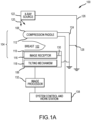
- FIG. 1A is a schematic view of an exemplary imaging system 100.
- FIG. 1B is a perspective view of the imaging system 100.
- the imaging system 100 immobilizes a patient's breast 102 for x-ray imaging (either or both of mammography and tomosynthesis) via a breast compression immobilizer unit 104 that includes a static breast support platform 106 and a moveable compression paddle 108.
- the breast support platform 106 and the compression paddle 108 each have a compression surface 110 and 112, respectively, that move towards each other to compress and immobilize the breast 102.
- the compression surface 110, 112 is exposed so as to directly contact the breast 102.
- the immobilizer unit 104 is supported on a first support arm 124 and the x-ray source 122 is supported on a second support arm 126.
- support arms 124 and 126 can rotate as a unit about an axis 128 between different imaging orientations such as CC and MLO, so that the system 100 can take a mammogram projection image at each orientation.
- the image receptor 116 remains in place relative to the platform 106 while an image is taken.
- the immobilizer unit 104 releases the breast 102 for movement of arms 124, 126 to a different imaging orientation.
- the support arm 124 stays in place, with the breast 102 immobilized and remaining in place, while at least the second support arm 126 rotates the x-ray source 122 relative to the immobilizer unit 104 and the compressed breast 102 about the axis 128.
- the system 100 takes plural tomosynthesis projection images of the breast 102 at respective angles of the beam 120 relative to the breast 102.
- the image receptor 116 may be tilted relative to the breast support platform 106 and in sync with the rotation of the second support arm 126.
- the tilting can be through the same angle as the rotation of the x-ray source 122, but may also be through a different angle selected such that the beam 120 remains substantially in the same position on the image receptor 116 for each of the plural images.
- the tilting can be about an axis 130, which can but need not be in the image plane of the image receptor 116.
- the tilting mechanism 118 that is coupled to the image receptor 116 can drive the image receptor 116 in a tilting motion.
- the breast support platform 106 can be horizontal or can be at an angle to the horizontal, e.g., at an orientation similar to that for conventional MLO imaging in mammography.
- the system 100 can be solely a mammography system, a CT system, or solely a tomosynthesis system, or a "combo" system that can perform multiple forms of imaging.
- An example of such a combo system has been offered by the assignee hereof under the trade name Selenia Dimensions.
- the image receptor 116 When the system is operated, the image receptor 116 produces imaging information in response to illumination by the imaging beam 120, and supplies it to an image processor 132 for processing and generating breast x-ray images.
- a system control and work station unit 138 including software controls the operation of the system and interacts with the operator to receive commands and deliver information including processed-ray images.
- One challenge with the imaging system 100 is how to immobilize and compress the breast 102 for the desired or required imaging.
- a health professional typically an x-ray technologist, generally adjusts the breast 102 within the immobilizer unit 104 while pulling tissue towards imaging area and moving the compression paddle 108 toward the breast support platform 106 to immobilize the breast 102 and keep it in place, with as much of the breast tissue as practicable being between the compression surfaces 110, 112. This can be a challenge for a technologist who is also operating the various controls of the imaging system 100.
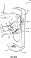
- FIGS. 2A-2C depict an exemplary imaging system 200 in various imaging orientations.
- FIG. 2A depicts the imaging system 200 in a craniocaudal (CC) imaging orientation
- FIG. 2B depicts the imaging system 200 in a breast positioning state for a right mediolateral oblique (RMLO) imaging orientation
- FIG. 2C depicts the imaging system 200 in a breast positioning state for left mediolateral oblique MLO (LMLO) imaging orientation.
- a tube head 208 of the system 200 is set in an orientation so as to be generally parallel to a gantry 206 of the system 200, or otherwise not normal to the flat portion of a support arm 210 against which the breast is placed.
- the technologist may more easily position the breast without having to duck or crouch below the tube head 208.
- the technologist may press a button on an interface of the system 200 (described below), so as to move the tube head 208 into position to begin an imaging procedure.
- the imaging system 200 includes a floor mount or base 202 for supporting the imaging system 200 on a floor.
- the gantry 206 extends upwards from the floor mount 202 and rotatably supports both the tube head 208 and a support arm 210.
- the tube head 208 and support arm 210 are configured to rotate discretely from each other and may also be raised and lowered along a face 212 of the gantry so as to accommodate patients of different heights.
- An x-ray source described elsewhere herein and not shown here, is disposed within the tube head 208.
- the support arm 210 includes a support platform 214 that includes therein an x-ray receptor and other components (not shown).
- a compression arm 216 extends from the support arm 210 and is configured to raise and lower linearly (relative to the support arm 210) a compression paddle 218 for compression of a patient breast during imaging procedures.
- the tube head 208 and support arm 210 may be referred to as a C-arm 209.
- a number of interfaces and display screens are disposed on the imaging system 200. These include a foot display screen 220, a gantry interface 222, a support arm interface 224, and a compression arm interface 226.
- the various interfaces 222, 224, and 226 may include one or more tactile buttons, knobs, switches, as well as one or more display screens, including capacitive touch screens with graphic user interfaces (GUIs) so as to enable user interaction with and control of the imaging system 200.
- GUIs graphic user interfaces
- the interfaces 222, 224, 226 may include control functionality that may also be available on a system control and work station (such as depicted in FIG. 1A ).
- any individual interface 222, 224, 226 may include functionality available on other interfaces 222, 224, 226, either continually or selectively, based at least in part on predetermined settings, user preferences, or operational requirements.
- the foot display screen 220 is primarily a display screen, though a capacitive touch screen might be utilized if required or desired.
- the gantry interface 222 may enable functionality such as: selection of the imaging orientation, display of patient information, adjustment of the support arm elevation or support arm angles (tilt or rotation), safety features, etc.
- the support arm interface 224 may enable functionality such as adjustment of the support arm elevation or support arm angles (tilt or rotation), adjustment of the compression arm elevation, safety features, etc.
- the compression arm interface 226 may enable functionality such as adjustment of the compression arm elevation, safety features, etc.
- one or more displays associated with the compression arm interface 226 may display more detailed information such as compression arm force applied, imaging orientation selected, patient information, support arm elevation or angle settings, etc.
- the foot display screen 220 may also display information such as displayed by the display(s) of the compression arm interface 226, or additional or different information, as required or desired for a particular application.
- the various interfaces and display screens disposed on the imaging system 200 may be used by a technologist during various imaging procedures performed on a patient.
- the technologies described herein improve efficiency of workflow which may be advantageous for a number of reasons. For example, efficient workflow can reduce the amount of time of an imaging procedure. This helps reduce the stress for the patient and allows the technologist to see a greater number of patients in a given time frame.
- Technologist performance may also be improved by utilizing the technologies described herein. That is, the technologist may be able to work more comfortably and avoid unnecessary or excessive bending, twisting, or straining during imaging procedures as the technologist works to position the patient and control the imaging system during imaging procedures. This can help reduce repetitive stress to the technologist, as well as reduce fatigue.
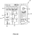
- FIGS. 3A-3C depict various views of a gantry interface 300 during imaging procedures and are generally described concurrently.
- a gantry interface is located on both sides of the gantry, so that the technologist will have access to the same controls and information regardless of which side she is working on.
- Each figure depicts a front view of the gantry interface 300, along with an enlarged view of a graphic user interface (GUI) 302 portion thereof for clarity.
- GUI graphic user interface
- the gantry interface 300 includes one or more tactile buttons, as well as a tactile SHUTDOWN button 306, which may be used to release the patient from compression in the event of an emergency such as a fire alarm, system failure, power failure, patient panic, etc.
- the SHUT DOWN button 306 may be connected to a battery-powered electrical circuit, a mechanical release, or a combination thereof to release the patient immediately and/or power the system off.
- the tactile buttons 304 may be used for any number of functions and may also include a COMMAND button 304a, the purpose of which is described below. Additionally, a TUBE HEAD MOVEMENT button 304b, which moves the tube head into or out of the way of the technologist is also depicted, as is a COMPRESSION RELEASE button 304c.
- the TUBE HEAD MOVEMENT button 304b may be used, e.g., to move the head out of the way of the technologist during positioning of the patient for an RMLO or LMLO imaging procedure (for example, to the position depicted in FIGS. 2B and 2C ).
- the COMPRESSION RELEASE button 304c may be used to release the patient from compression after an imaging procedure.
- Other or additional buttons having other functionality may be utilized.
- the GUI 302 includes a plurality of fields that provide information regarding the patient, the imaging system, and settings thereof. Such patient information may include name, age, medical history, prior x-ray image data, etc.
- Information regarding the imaging system may include imaging orientation settings, as depicted by an imaging orientation setting field 308, which includes depictions of the imaging orientation for each breast (e.g., left CC (LCC), right CC (RCC), RMLO, LMLO)). These depictions may be highlighted as appropriate or may include a control component where the technologist may select a desired imaging orientation and the system may move to the selected position. The selected position may be associated with preset angles, x-ray doses, or other settings.
- a C-arm positioning field 310 may include height controls 312 to raise and lower the C-arm, tilt controls 314 to tilt the C-arm towards and away from the gantry, and rotational controls 316 to rotate the C-arm relative to the gantry.
- FIG. 3A depicts a selectively illuminable COMMAND field 320 that illuminates when C-arm movement is possible (e.g., when the patient breast is not compressed). For example, the technologist may enter desired settings as regards to C-arm tilt, rotation, height, etc. for a particular procedure. Sensors in the compression arm or elsewhere may detect whether a breast of a patient is presently under compression. If so, the illuminable COMMAND field 320 will not light, or may blink as a warning.
- the technologist must first release compression (e.g., via the COMPRESSION RELEASE button 304c), thus releasing the patient from compression. Once released, the field 320 (or associated COMMAND button 304a) may then illuminate. Once the technologist presses the COMMAND button 304a, the C-arm moves to its next position automatically, while the technologist assists the patient for the next imaging procedure.
- compression e.g., via the COMPRESSION RELEASE button 304c
- FIG. 3B depicts an alternative display condition in the C-arm status field 318.
- the technologist may selectively enter a desired setting of the C-arm, for example, a desired height, tilt position, or in this case, rotational position.
- a desired setting of the C-arm for example, a desired height, tilt position, or in this case, rotational position.
- an accept control 322 is pressed and the selectively illuminable COMMAND field 320 is illuminated (as depicted in FIG. 3C ) if the system detects existing breast compression, thus requiring breast release prior to C-arm movement, as described above.
- the new position of the C-arm may also be depicted in the C-arm status field 318.
- rotation of the C-arm is primarily depicted with regard to FIGS.
- GUI 302 is depicted in FIGS. 3A-3C depicts selectable controls and display fields
- the GUI may also display images previously obtained from patients (e.g., historical images), images obtained during the present procedure, or other medical information (e.g., patient physical conditions that may make standing or breast placement difficult).
- the gantry interface 300 may display a significant amount of information for the technologist, information that is typically only available at the remote workstation.
- FIG. 4 depicts a support arm interface 400 that includes a plurality of tactile buttons.
- the support arm interface 400 includes controls utilized to position the C-arm, as well as the compression paddle.
- the depicted support arm interface includes a C-arm height and rotation button 402, as well as C-arm tilt buttons 404.
- the C-arm height and rotation button 402 may be a multi-way toggle button that allows for activation of the various controls by pressing various locations on the button 402.
- the C-arm height and rotation button 402 may be a plurality of discrete buttons.
- the C-arm height and rotation button 402 and the C-arm tilt buttons 404 thus enable functionality somewhat similar to that of the gantry interface depicted above.
- buttons 406 can include those controls required for raising and lowering the compression paddle, releasing the breast from compression, automatic positioning (e.g., of the C-arm, the compression arm, or both), etc.
- the support arm interface 400 depicts tactile buttons, another example may utilize a capacitive touch screen having a GUI, or any combination of tactile and screen inputs or controls.
- one support arm interface 400 is disposed on either side of the support arm; an arrangement of the buttons that is arranged in a mirror image on the opposite side of the support arm is contemplated in some examples.
- FIG. 5 depicts a top view of a compression arm 500 having a compression arm interface 502.
- the compression arm interface 502 includes a plurality of compression arm display screens 504, which may be simply display screens or capacitive touch screens, for displaying information relevant to the imaging system and, more specifically, the position of the C-arm, elements thereof, and the compression arm 500 and compression paddle 505.
- a plurality of tactile buttons 506 are also present and may be utilized for increasing or decreasing pressure applied by the compression paddle 505, automatic releasing of the breast from compression, adjusting a distance of the compression arm body 512 from the support arm 513, etc.
- the compression arm 500 may be manipulated by one or more rotary knobs 508 so as to increase or decrease pressure on the breast.
- An additional patient display screen 510 may be disposed on a patient-facing portion of the body 512 of the compression arm 500. While the patient display screen 510 may display a limited amount of information, such as patient name and instructions during imaging procedures (e.g., "relax", "hold breath”, etc.), the compression arm display screens 504 may display additional information that aids the technologist during positioning of the breast and imaging procedures.
- patient display screen 510 may display a limited amount of information, such as patient name and instructions during imaging procedures (e.g., "relax", "hold breath”, etc.)
- the compression arm display screens 504 may display additional information that aids the technologist during positioning of the breast and imaging procedures.
- Information displayed on the compression arm display screens 504 typically relates to breast compression and the same information is typically displayed on both the left 504L and right 504R display screens 504.
- This information may include imaging orientation (e.g., RMLO, LMLO, RCC, LCC), pressure applied to the breast, desired/target/actual breast thickness, C-arm status (rotational and tilt angle), automatic exposure control (AEC) setting, etc.
- system settings initially set by the technologist at other interfaces e.g., gantry interface or support arm interface
- a read-ready orientation of each compression arm display screen 504 may be set automatically by the imaging system to improve readability of each display screen 504 during breast positioning and imaging procedures.
- FIGS. 6A-6C depict various views of compression arm interface display screens 504L, 504R during breast positioning and imaging procedures.
- the read-ready orientation of each of the display screens 504L, 504R may be set so as to change during different stages of the breast positioning procedures.
- FIG. 6A depicts the left 504L and right 504R display screens when the imaging system is in a CC (either LCC or RCC) imaging orientation (such as depicted in FIG. 2A ).
- CC either LCC or RCC
- each display screen is set in a default position. That is, in the default position, a footer edge 550 of each display screen 504L, 504R is positioned so as to be proximate a technologist standing adjacent that particular side of the imaging system.
- the left display screen 504L has a footer edge 550 facing towards the left of the imaging system, such that a technologist standing on that side may easily read the information on the screen 504L, which appears upright to the technologist.
- the right display screen 504R has a footer edge 550 facing towards the right of the imaging system, such that a technologist standing on that side may easily read the information on the screen 504R, which appears upright to the technologist. Since a technologist may stand on either side of the imaging system during a CC imaging operation, regardless of the technologist's position, the information displayed on the screens 504L, 504R may be easily read. This read-ready orientation of each compression arm display screen 504L, 504R may change as required during other imaging procedures, as described below.
- FIG. 6B depicts the display screens 504L, 504R when the imaging system is in the RMLO position. In this position, a number of conditions are present.
- the support arm is rotated to the position depicted in FIG. 2B , while the tube head is rotated to a position to avoid interference with the technologist during breast positioning.
- the technologist will typically be standing on the right side of the imaging system and patient.
- the support arm and compression arm positioned as depicted, the right display screen 504R is very difficult to see by a technician of average height unless the technician is crouching.
- the read-ready orientation of the left display screen 504L changes to an inverted position, where the footer edge 550 is disposed so as to face opposite of its default position (that is, it faces towards the opposite side of the imaging system from where it is disposed). That is, the footer edge of the left display screen 504L is oriented towards the right of the compression arm and imaging system. The footer edge 550 of the right display screen 504R remains in the default position. In this orientation, a technologist standing on the right side of the imaging system and patient is able to read the left display screen 504L, which is more clearly facing in the direction of the technologist.
- FIG. 6C depicts the display screens 504L, 504R when the imaging system is in the LMLO position. In this position, a number of conditions are present.
- the support arm is rotated to the position depicted in FIG. 2C , while the tube head is rotated to a position to avoid interference with the technologist during breast positioning.
- the technologist will typically be standing on the left side of the imaging system and patient.
- the support arm and compression arm positioned as depicted, the left display screen 504L is very difficult to see by a technician of average height unless the technician is crouching.
- the read-ready orientation of the right display screen 504R changes to an inverted position, where the footer edge 550 is disposed so as to face opposite of its default position (that is, it faces towards the opposite side of the imaging system from where it is disposed). That is, the footer edge of the right display screen 504R is oriented towards the left of the compression arm and imaging system. The footer edge 550 of the left display screen 504L remains in the default position. In this orientation, a technologist standing on the left side of the imaging system and patient is able to read the right display screen 504R, which is more clearly facing in the direction of the technologist.
- FIGS. 7A-7C depict various views of a foot display screen 600 during imaging procedures.
- the read-ready orientation of the foot display screens 600 may be set so as to change during different stages of the breast positioning and imaging procedures.
- the foot display screen 600 may be disposed on a ramp 602 that is disposed at an angle to the foot mount 604. An angle of the ramp 602 may improve a technologist's ability to view the foot display screen 600 in any position.
- the foot display screen 600 may display information similar to that displayed by the compression arm display screens 504 or other information as required or desired.
- FIG. 7A depicts the foot display screen 600 when the imaging system is in a CC (either LCC or RCC) imaging orientation (such as depicted in FIG. 2A ).
- CC either LCC or RCC
- FIG. 7A depicts the foot display screen 600 when the imaging system is in a CC (either LCC or RCC) imaging orientation (such as depicted in FIG. 2A ).
- the display of the foot display screen is set in a default, landscape position.
- the term "landscape" has the meaning typically understood by a person of skill in the art.
- a footer edge 550 of the foot display screen 504L, 504R is positioned so as to face the patient. Since a technologist may stand on either side of the imaging system during a CC imaging operation, regardless of the technologist's position, the information displayed on the foot display screen 600 may be easily read. This read-ready orientation of the foot display screen 600 may change as required during other imaging procedures.
- FIG. 7B depicts the foot display screen 600 when the imaging system is in the RMLO position. In this position, a number of conditions are present.
- the support arm is rotated to the position depicted in FIG. 2B , while the tube head is rotated to a position to avoid interference with the technologist during breast positioning.
- the technologist will typically be standing on the right side of the imaging system and patient.
- the read-ready orientation of the foot display screen 600 changes to right-biased portrait orientation, where the footer edge 650 is disposed so as to face towards the right side of the imaging system.
- the term "portrait" has the meaning typically understood by a person of skill in the art. In this orientation, a technologist standing on the right side of the imaging system and patient is able to read the foot display screen 600, if the compression arm displays 504 are not easily viewable.
- FIG. 7C depicts the foot display screen 600 when the imaging system is in the LMLO position. In this position, a number of conditions are present.
- the support arm is rotated to the position depicted in FIG. 2C , while the tube head is rotated to a position to avoid interference with the technologist during breast positioning.
- the technologist will typically be standing on the left side of the imaging system and patient.
- the read-ready orientation of the foot display screen 600 changes to left-biased portrait orientation, where the footer edge 650 is disposed so as to face towards the left side of the imaging system. In this orientation, a technologist standing on the left side of the imaging system and patient is able to read the foot display screen 600, if the compression arm displays 504 are not easily viewable.
- the various GUIs and display screens described herein may also alter the presentation of information based on predetermined conditions. For example, for screens that display compression force information, the data associated therewith may change in presentation (e.g., color, strobe effect, font size, etc.) as a threshold is approached or exceeded. This threshold could be associated with a previously-identified threshold that typically or previously caused a patient discomfort, or some other threshold or criteria. Additionally, the GUIs and display screens may display instructions for performing particular imaging procedures, which may be helpful for training purposes. Further, the GUIs and display screens may display menus from which various actions may be selected. Other presentations of information are contemplated.
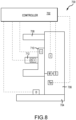
- FIG. 8 depicts a schematic diagram of an imaging system 700.
- the imaging system 700 may be self-contained, but often includes an associated controller 702, which may be a remote computer or custom workstation that may be connected to a hospital network or just to the imaging system 700 itself.
- the controller 702 may be contained within the imaging system 700 itself (e.g., in a gantry 706).
- the imaging system 700 includes a foot mount or base 704, the gantry 706, a tube head 708, a support arm 710, and a compression arm 712. A number of interfaces I, motors M, sensors S, and displays D are depicted.
- the imaging systems described herein utilize one or more sensors S to determine the display settings of the foot display D and the displays D associated with the interface I of the compression arm 712. Again, a plurality compression arm displays D are utilized, but only a single display D is shown in FIG. 8 for clarity.
- the sensors utilized may be a sensor that is associated with the motor M that is used to rotate the support arm 710 relative to the gantry 706.
- the sensors utilized may be a position sensor connected directly to a feature of the support arm 710 itself.
- a gyroscopic sensor disposed on the support arm 710 may be utilized.
- the signal sent from the motor, position, gyroscopic (or other) sensors detect positional relationships of one component of the system 700 to another component. Based on those signals, the controller 702 may send signals that set the read-ready orientations of the various displays D on the compression arm 712 or the display D on the foot 704.
- the sensors need not be positional sensors such as described above, but may be associated with one or more of the interfaces I.
- command or other signals e.g., indicative of a GUI selection, button press, knob adjustment, etc.
- an interface I located on a left side of the imaging system 700 e.g., the left interface(s) on the gantry 706, support arm 710, or compression arm 712
- the controller 702 may set the read-ready orientations of the various displays D on the compression arm 712 or the display D on the foot 704 so as to be read from the left side.
- signals received from such interface sensors may be ignored if the imaging system 700 is in the CC imaging position, for reasons described above.
- one or more proximity sensors S P may be disposed at various locations around the imaging system 700 (e.g., on either side of the base 704, gantry 706, etc.). These sensors S P may be motion, heat, or other types of sensors that detect the presence of a person (e.g., the technologist) on one side of the imaging system 700. A signal associated therewith may be sent to the controller 702, to that the controller 702 may set the read-ready orientations of the various displays D on the compression arm 712 or the display D on the foot 704 so as to be read from the appropriate side.
- FIG. 9 depicts a method 800 of setting a display orientation for a display in an imaging system.
- the method 800 may be performed on imaging systems such as those described herein (e.g., those with multiple display screens and interfaces in various locations thereon).
- the method 800 includes an identification of the types of displays present, operation 802. As described above, multiple displays may be utilized, such as compression arm display screens and foot display screens.
- the method 800 begins with sending a default display signal to the compression arm display screen, operation 804. As described above, multiple compression arm display screens may be utilized. In that case, the method 800 may be performed for each compression arm display screen.
- this default display signal will set the read-ready orientation to a default setting, where the compression arm display screen may be oriented so as to be easily readable by a technologist standing on the side of the imaging system where the compression arm display screen is located.
- the method continues with receiving a condition signal, operation 806.
- the condition signal may be received from a sensor such as described above or may be a command or other signal sent from, for example, an interface on a particular component and/or side of the imaging system.
- the sensor detects a position of the support arm and may be an encoder, a gyroscope, or some other type of sensor.
- condition signal is compared to a threshold and, if it meets that threshold, flow branches YES and the method sends an inverted display signal to the compression arm display screen, operation 810.
- this signal may only be sent to a single one of the plurality of screens
- the method begins with sending a default display signal to the foot display screen, operation 812. This may occur substantially simultaneously with operation 804. In general, this default display signal will set the read-ready orientation to a default setting, where the foot display screen may be oriented so as to be easily readable by a technologist standing on either side of the imaging system.
- the method continues with receiving a condition signal, operation 814.
- the condition signal may be received from a sensor such as described above or may be a command or other signal sent from, for example, an interface on a particular component and/or side of the imaging system.
- the sensor detects a position of the support arm and may be an encoder, a gyroscope, or some other type of sensor.
- the method returns to operation 808, where the condition signal is compared to a threshold and, if it meets that threshold, flow branches YES and the method 800 sends an altered display signal to the compression arm display screen, operation 810.
- the threshold for comparison regarding the foot display screen may be different than that for the compression arm display screen. That is, the read-ready orientation of the foot display screen may be set when the compression arm reaches a first angle, while the read-ready orientation of the compression arm display screen may be set when the compression arm reaches a second angle.
- Sending the altered display signal may include setting the foot display screen to either a portrait or landscape mode, as well as a bias mode to either the left or the right of the imaging device, depending on the signal and the threshold.
- Optional operation 818 may send a signal to a light associated with a tactile button based on the condition signal and/or a command input. This aspect of the method helps signal the technologist to take a further action (e.g., releasing of the patient from compression) prior to enabling movement of the support arm.
- FIG. 10A depicts an example of a suitable operating environment 940 for use with the present examples.
- the computing device 940 is a suitable operating environment in which one or more of the present examples can be implemented.
- This operating environment may be incorporated directly into a imaging system, a workstation, or may be incorporated into a computer system discrete from, but used to control or process data from, the imaging systems described herein.
- This is only one example of a suitable operating environment and is not intended to suggest any limitation as to the scope of use or functionality.
- operating environment 940 typically includes at least one processing unit 942 and memory 944.
- memory 944 storing, among other things, instructions to perform the display setting and control methods disclosed herein
- memory 944 can be volatile (such as RAM), non-volatile (such as ROM, flash memory, etc.), or some combination of the two.
- This most basic configuration is illustrated in FIG. 10A by dashed line 946.
- environment 940 can also include storage devices (removable, 948, and/or non-removable, 951) including, but not limited to, solid-state devices, magnetic or optical disks, or tape.
- environment 940 can also have input device(s) 954 such as touch screens, keyboard, mouse, pen, voice input, etc., and/or output device(s) 956 such as a display, speakers, printer, etc.
- input device(s) 954 such as touch screens, keyboard, mouse, pen, voice input, etc.
- output device(s) 956 such as a display, speakers, printer, etc.
- Also included in the environment can be one or more communication connections 952, such as LAN, WAN, point to point, Bluetooth, RF, etc.
- Operating environment 940 typically includes at least some form of computer readable media.
- Computer readable media can be any available media that can be accessed by processing unit 942 or other devices having the operating environment.
- Computer readable media can include computer storage media and communication media.
- Computer storage media includes volatile and nonvolatile, removable and non-removable media implemented in any method or technology for storage of information such as computer readable instructions, data structures, program modules or other data.
- Computer storage media includes, RAM, ROM, EEPROM, flash memory or other memory technology, CD-ROM, digital versatile disks (DVD) or other optical storage, magnetic cassettes, magnetic tape, magnetic disk storage or other magnetic storage devices, solid state storage, or any other tangible and non-transitory medium which can be used to store the desired information.
- Communication media embodies computer readable instructions, data structures, program modules, or other data in a modulated data signal such as a carrier wave or other transport mechanism and includes any information delivery media.
- modulated data signal means a signal that has one or more of its characteristics set or changed in such a manner as to encode information in the signal.
- communication media includes wired media such as a wired network or directwired connection, and wireless media such as acoustic, RF, infrared and other wireless media. Combinations of the any of the above should also be included within the scope of computer readable media.
- the operating environment 940 can be a single computer operating in a networked environment using logical connections to one or more remote computers.
- the remote computer can be a personal computer, a server, a router, a network PC, a peer device or other common network node, and typically includes many or all of the elements described above as well as others not so mentioned.
- the logical connections can include any method supported by available communications media.
- Such networking environments are commonplace in hospitals, offices, enterprise-wide computer networks, intranets and the Internet.
- the components described herein include such modules or instructions executable by computer system 940 that can be stored on computer storage medium and other tangible mediums and transmitted in communication media.
- Computer storage media includes volatile and non-volatile, removable and non-removable media implemented in any method or technology for storage of information such as computer readable instructions, data structures, program modules, or other data. Combinations of any of the above should also be included within the scope of readable media.
- computer system 940 is part of a network that stores data in remote storage media for use by the computer system 940.
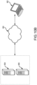
- FIG. 10B depicts an example of a network in which the various systems and methods disclosed herein may operate.
- a client device such as client device 962
- a client device may be a laptop, a personal computer, a smart phone, a PDA, a netbook, or any other type of computing device, such as the computing device in FIG. 10A .
- servers 964 and 966 may be any type of computing device, such as the computing device illustrated in FIG. 10A .
- Network 968 may be any type of network capable of facilitating communications between the client device and one or more servers 964 and 966. Examples of such networks include, but are not limited to, LANs, WANs, cellular networks, and/or the Internet.
- processing of data and performance of the methods described herein may be accomplished with the use of one or more server devices.
- a single server such as server 964 may be employed to assist in processing data and performing the methods disclosed herein.
- Client device 962 may interact with server 964 via network 968.
- the client device 962 may also perform functionality disclosed herein, such as scanning and processing data, which can then be provided to servers 964 and/or 966.
- the methods disclosed herein may be performed using a distributed computing network, or a cloud network.
- the methods disclosed herein may be performed by two or more servers, such as servers 964 and 966.
- servers 964 and 966 may be performed by two or more servers, such as servers 964 and 966.
- a particular network example is disclosed herein, one of skill in the art will appreciate that the systems and methods disclosed herein may be performed using other types of networks and/or network configurations.
- the data sent to the servers and received from the servers may be encrypted.
- the data may also be stored in an encrypted manner both locally and on the servers.
Landscapes
- Health & Medical Sciences (AREA)
- Life Sciences & Earth Sciences (AREA)
- Engineering & Computer Science (AREA)
- Medical Informatics (AREA)
- Optics & Photonics (AREA)
- Biomedical Technology (AREA)
- Biophysics (AREA)
- High Energy & Nuclear Physics (AREA)
- Veterinary Medicine (AREA)
- Nuclear Medicine, Radiotherapy & Molecular Imaging (AREA)
- Public Health (AREA)
- Pathology (AREA)
- Radiology & Medical Imaging (AREA)
- Physics & Mathematics (AREA)
- Heart & Thoracic Surgery (AREA)
- Molecular Biology (AREA)
- Surgery (AREA)
- Animal Behavior & Ethology (AREA)
- General Health & Medical Sciences (AREA)
- Human Computer Interaction (AREA)
- Dentistry (AREA)
- Oral & Maxillofacial Surgery (AREA)
- Apparatus For Radiation Diagnosis (AREA)
Claims (12)
- Brustbildgebungssystem, umfassend:eine Bodenhalterung (202, 704);ein Gerüst (206, 706), das durch die Bodenhalterung (202, 704) gestützt wird;eine Rohrarmanordnung (208, 708), die mit dem Gerüst (206, 706) drehbar verbunden ist;einen Stützarm (210, 710), der mit der Rohrarmanordnung (208, 708) unabhängig drehbar verbunden ist, wobei der Stützarm (210, 710) wahlweise in einer Vielzahl von Drehpositionen positionierbar ist, umfassend: eine erste abgewinkelte Position, eine zweite abgewinkelte Position und eine waagerechte Position, die zwischen der ersten abgewinkelten Position und der zweiten abgewinkelten Position eingerichtet ist;einen Kompressionsarm (216, 500, 712), der auf dem Stützarm (210, 710) linear positionierbar ist, wobei der Kompressionsarm (216, 500, 712) konfiguriert ist, um eine Brustkompressionsplatte zu stützten; undeine Vielzahl von Armanzeigebildschirmen, die auf einer oberen Oberfläche des Kompressionsarms eingerichtet ist;dadurch gekennzeichnet, dass das Brustbildgebungssystem ferner umfasst:ein Sensor; undeine Steuerung, die mit dem Sensor wirkgekoppelt und konfiguriert ist, um eine lesebereite Ausrichtung jedes der Vielzahl von Armanzeigebildschirmen mindestens teilweise basierend auf einem Signal zu ändern, das von dem Sensor empfangen wird,wobei, wenn sich der Stützarm in der ersten abgewinkelten Position befindet:sich ein erster Armanzeigebildschirm der Vielzahl von Armanzeigebildschirmen in einer standardmäßigen lesebereiten Ausrichtung befindet undsich ein zweiter Armanzeigebildschirm der Vielzahl von Armanzeigebildschirmen in einer umgekehrten lesebereiten Ausrichtung befindet.
- Brustbildgebungssystem nach Anspruch 1, wobei der Sensor konfiguriert ist, um die Drehposition des Stützarms zu erkennen, und/oder wobei der Sensor konfiguriert ist, um eine Eingabe auf einer Benutzerschnittstelle des Brustbildgebungssystems zu erkennen.
- Brustbildgebungssystem nach einem der Ansprüche 1 bis 2, wobei, wenn sich der Stützarm in der waagerechten Position befindet:sich der erste Armanzeigebildschirm der Vielzahl von Armanzeigebildschirmen in einer standardmäßigen lesebereiten Ausrichtung befindet undsich der zweite Armanzeigebildschirm der Vielzahl von Armanzeigebildschirmen in einer standardmäßigen lesebereiten Ausrichtung befindet, wobei vorzugsweise, wenn sich der Stützarm in der zweiten abgewinkelten Position befindet:sich der erste Armanzeigebildschirm der Vielzahl von Armanzeigebildschirmen in einer umgekehrten lesebereiten Ausrichtung befindet undsich der zweite Armanzeigebildschirm der Vielzahl von Armanzeigebildschirmen in einer standardmäßigen lesebereiten Ausrichtung befindet.
- Brustbildgebungssystem nach einem der Ansprüche 1 bis 3, ferner umfassend einen Fußanzeigebildschirm, der auf der Bodenhalterung eingerichtet ist, wobei die Steuerung konfiguriert ist, um eine lesebereite Ausrichtung des Fußanzeigebildschirms mindestens teilweise basierend auf dem Signal zu ändern, das von dem Sensor empfangen wird, und wobei vorzugsweise:wenn sich der Stützarm in der ersten abgewinkelten Position befindet, sich der Fußanzeigebildschirm in einer ersten vorgespannten lesebereiten Ausrichtung befindet;wenn sich der Stützarm in der zweiten abgewinkelten Position befindet, sich der Fußanzeigebildschirm in einer zweiten vorgespannten lesebereiten Ausrichtung befindet, undwenn sich der Stützarm in der waagerechten Position befindet, sich der Fußanzeigebildschirm in einer standardmäßigen lesebereiten Ausrichtung befindet, wobei vorzugsweise der Fußanzeigebildschirm in einem ersten Modus sowohl in der ersten vorgespannten lesebereiten Ausrichtung als auch in der zweiten vorgespannten lesebereiten Ausrichtung und in einem zweiten Modus in der standardmäßigen lesebereiten Ausrichtung konfiguriert ist, wobei vorzugsweise der erste Modus ein Hochformatmodus ist und der zweite Modus ein Querformatmodus ist.
- Brustbildgebungssystem nach einem der Ansprüche 1 bis 4, wobei jeder der Vielzahl von Armanzeigebildschirmen einen kapazitiven Berührungsbildschirm umfasst und/oder wobei die erste abgewinkelte Position und die zweite abgewinkelte Position mediolateralen schrägen Bildgebungspositionen entsprechen und wobei die waagerechte Position einer kraniokaudalen Bildgebungsposition entspricht.
- Brustbildgebungssystem nach einem der Ansprüche 1 bis 5, wobei die Vielzahl von Armanzeigebildschirmen einen ersten Armanzeigebildschirm, einen zweiten Armanzeigebildschirm und einen dritten Armanzeigebildschirm umfasst, wobei der erste Armanzeigebildschirm und der zweite Armanzeigebildschirm konfiguriert sind, um im Wesentlichen ähnliche Informationen anzuzeigen, und wobei der dritte Armanzeigebildschirm konfiguriert ist, um mindestens teilweise andere Informationen anzuzeigen als die des ersten Armanzeigebildschirms und des zweiten Armanzeigebildschirms.
- Brustbildgebungssystem nach einem der Ansprüche 1 bis 6, ferner umfassend:eine Gerüstschnittstelle, die an dem Gerüst eingerichtet ist;eine Stützarmschnittstelle, die an dem Stützarm eingerichtet ist; undeine Kompressionsarmschnittstelle, die auf einer oberen Oberfläche des Kompressionsarms eingerichtet ist, wobei die Steuerung vorzugsweise konfiguriert ist, um an mindestens einer der Gerüstschnittstelle und der Kompressionsarmschnittstelle eine Funktionalität der Stützarmschnittstelle zu aktivieren, wenn der Stützarm in mindestens einer der ersten abgewinkelten Position und der zweiten abgewinkelten Position eingerichtet ist, wobei die Funktionalität vorzugsweise eine Kraftausübung durch den Kompressionsarm umfasst, wobei die Steuerung vorzugsweise konfiguriert ist, um eine Präsentation von Informationen an mindestens einer der Gerüstschnittstelle, der Stützarmschnittstelle und der Kompressionsarmschnittstelle einzustellen, wenn ein Signal von einem Feedback-Sensor einen Schwellenwert erfüllt, wobei der Feedback-Sensor vorzugsweise einen Druck erfasst, der durch den Kompressionsarm ausgeübt wird, und wobei die Veränderung das Ändern von mindestens einem von visuellen Daten und einem akustischen Signal umfasst, wobei die Kompressionsarmschnittstelle vorzugsweise mindestens einen kapazitiven Berührungsbildschirm und mindestens einen Tastschalter umfasst, wobei die Gerüstschnittstelle vorzugsweise einen Tastschalter umfasst, und wobei die Steuerung konfiguriert ist, um vor dem Aktivieren eines Positionierens des Stützarms ein Signal an ein Licht zu senden, das dem Tastschalter zugeordnet ist.
- Verfahren zum Einstellen einer Anzeigeausrichtung einer Kompressionsarmanzeige eines Bildgebungssystems nach einem der Ansprüche 1 bis 7, das Verfahren umfassend:Senden eines Standardanzeigesignals an die Kompressionsarmanzeige, wobei die Anzeige auf dem Kompressionsarm des Bildgebungssystems eingerichtet ist;Empfangen eines Zustandssignals von dem Sensor, der dem Bildgebungssystem zugeordnet ist; undfalls das Zustandssignal einen ersten Schwellenwert erfüllt, Senden eines invertierten Anzeigesignals an die Kompressionsarmanzeige.
- Verfahren nach Anspruch 8, wobei das Bildgebungssystem ferner eine Fußanzeige umfasst, und wobei das Verfahren ferner umfasst:Senden eines Standardanzeigesignals an die Fußanzeige, im Wesentlichen gleichzeitig mit dem Senden des Standardanzeigesignals an die Kompressionsarmanzeige; undfalls das Zustandssignal einen zweiten Schwellenwert erfüllt, Senden eines veränderten Anzeigesignals an die Fußanzeige, und/oder wobei die Kompressionsarmanzeige eine Vielzahl von Kompressionsarmanzeigen umfasst, wobei das umgekehrte Anzeigesignal vorzugsweise nur an eine der Vielzahl von Kompressionsarmanzeigen gesendet wird.
- Verfahren nach einem von Anspruch 9, wobei das Senden des veränderten Anzeigesignals das Einstellen umfasst von: (a) mindestens einem von einem Hochformatanzeigemodus und einem Querformat-Anzeigemodus, und (b) einem Erstvorspannmodus und einem Zweitvorspannmodus.
- Verfahren nach einem der Ansprüche 8 bis 10, wobei der Sensor mindestens einen von einem Positionssensor, einem Näherungssensor und einem Eingabesensor umfasst, wobei der Eingabesensor vorzugsweise mindestens einer von einer Kompressionsarmschnittstelle, einer Stützarmschnittstelle und einer Portalschnittstelle zugeordnet ist, und/oder wobei der Positionssensor konfiguriert ist, um eine Position eines Stützarms zu erkennen, wobei der Positionssensor vorzugsweise mindestens eines von einem Gyrosensor und einen Codierer umfasst.
- Verfahren nach einem der Ansprüche 8 bis 11, ferner umfassend das Senden eines Signals an ein Licht, das einem Tastschalter zugeordnet ist, basierend mindestens auf dem Zustandssignal und einer Befehlseingabe.
Applications Claiming Priority (2)
| Application Number | Priority Date | Filing Date | Title |
|---|---|---|---|
| US201862735268P | 2018-09-24 | 2018-09-24 | |
| PCT/US2019/052721 WO2020068845A1 (en) | 2018-09-24 | 2019-09-24 | Multi-screen imaging system for improved workflow |
Publications (2)
| Publication Number | Publication Date |
|---|---|
| EP3856036A1 EP3856036A1 (de) | 2021-08-04 |
| EP3856036B1 true EP3856036B1 (de) | 2024-08-14 |
Family
ID=68165795
Family Applications (1)
| Application Number | Title | Priority Date | Filing Date |
|---|---|---|---|
| EP19783854.3A Active EP3856036B1 (de) | 2018-09-24 | 2019-09-24 | Mehrschirm-abbildungssystem für verbesserten arbeitsablauf |
Country Status (4)
| Country | Link |
|---|---|
| US (4) | US12011305B2 (de) |
| EP (1) | EP3856036B1 (de) |
| ES (1) | ES2990213T3 (de) |
| WO (1) | WO2020068845A1 (de) |
Families Citing this family (19)
| Publication number | Priority date | Publication date | Assignee | Title |
|---|---|---|---|---|
| WO2020068845A1 (en) | 2018-09-24 | 2020-04-02 | Hologic, Inc. | Multi-screen imaging system for improved workflow |
| JP7413223B2 (ja) * | 2020-09-30 | 2024-01-15 | 富士フイルム株式会社 | 制御装置、制御方法、及び制御プログラム |
| JP7531365B2 (ja) | 2020-10-29 | 2024-08-09 | 富士フイルム株式会社 | 乳房撮影装置 |
| US12186119B2 (en) * | 2021-10-05 | 2025-01-07 | Hologic, Inc. | Interactive model interface for image selection in medical imaging systems |
| USD1093611S1 (en) * | 2021-10-08 | 2025-09-16 | Echosens | Console for an Elastography apparatus |
| CN114366132A (zh) * | 2021-12-16 | 2022-04-19 | 北京达影科技有限公司 | 一种摆位控制方法及乳腺机、控制装置、存储介质 |
| JP1731412S (ja) * | 2022-03-31 | 2022-12-06 | 乳房エックス線撮影機 | |
| JP1735014S (ja) * | 2022-03-31 | 2023-01-19 | 乳房エックス線撮影機 | |
| JP1734948S (ja) * | 2022-03-31 | 2023-01-19 | 乳房エックス線撮影機 | |
| USD1032843S1 (en) | 2022-09-27 | 2024-06-25 | Hologic, Inc. | Imaging system |
| DE102022210282B4 (de) | 2022-09-28 | 2024-04-04 | Siemens Healthineers Ag | Mammographiesystem zur Aufnahme eines Röntgenaufnahmedatensatzes aufweisend eine Unterbrechungseinheit sowie ein Verfahren dazu |
| USD1116114S1 (en) * | 2022-12-16 | 2026-03-03 | Siemens Healthineers Ag | Medical imaging device |
| JP2025073458A (ja) * | 2023-10-26 | 2025-05-13 | 富士フイルム株式会社 | マンモグラフィ装置、マンモグラフィ装置の表示方法、及び医用画像取得システム |
| USD1071222S1 (en) * | 2024-02-06 | 2025-04-15 | Yofo (hefei) Medical Technology Co., Ltd. | Dental CT scanner |
| USD1118932S1 (en) * | 2024-02-28 | 2026-03-17 | Metaltronica S.P.A. | Irradiation apparatus |
| JP1803712S (ja) * | 2024-03-13 | 2025-07-15 | 血管造影エックス線機器 | |
| USD1093617S1 (en) * | 2024-08-24 | 2025-09-16 | Canfield Scientific, Incorporated | Facial imaging apparatus |
| USD1101152S1 (en) * | 2024-09-26 | 2025-11-04 | GE Precision Healthcare LLC | Imaging apparatus |
| USD1121819S1 (en) * | 2024-09-26 | 2026-04-07 | GE Precision Healthcare LLC | Imaging apparatus |
Family Cites Families (39)
| Publication number | Priority date | Publication date | Assignee | Title |
|---|---|---|---|---|
| US7831296B2 (en) * | 2002-11-27 | 2010-11-09 | Hologic, Inc. | X-ray mammography with tomosynthesis |
| WO2005104729A2 (en) * | 2004-04-26 | 2005-11-10 | U-Systems, Inc. | Versatile breast ultrasound scanning |
| US8311305B2 (en) | 2006-10-18 | 2012-11-13 | Kabushiki Kaisha Toshiba | X-ray diagnostic apparatus, image processing apparatus, and method of calculating filter coefficients used for image formation processing in x-ray diagnostic apparatus and the like |
| USD563553S1 (en) | 2006-10-30 | 2008-03-04 | Kabushiki Kaisha Toshiba | X-ray apparatus for medical treatment |
| JP2009018048A (ja) * | 2007-07-12 | 2009-01-29 | Fujifilm Corp | 医用画像表示装置、方法及びプログラム |
| US8126226B2 (en) * | 2007-09-20 | 2012-02-28 | General Electric Company | System and method to generate a selected visualization of a radiological image of an imaged subject |
| FR2924010B1 (fr) * | 2007-11-23 | 2010-11-26 | Gen Electric | Perfectionnements aux appareils de mammographie |
| US8817048B2 (en) * | 2009-07-17 | 2014-08-26 | Apple Inc. | Selective rotation of a user interface |
| US8799013B2 (en) * | 2009-11-24 | 2014-08-05 | Penrad Technologies, Inc. | Mammography information system |
| US8565373B2 (en) * | 2009-12-29 | 2013-10-22 | General Electric Company | Method and system for automatically positioning a mammography imaging system |
| USD659833S1 (en) | 2011-01-27 | 2012-05-15 | Fujifilm Corporation | Mammography equipment |
| USD659832S1 (en) * | 2011-01-27 | 2012-05-15 | Fujifilm Corporation | Mammography equipment |
| US8842806B2 (en) * | 2012-04-03 | 2014-09-23 | Carestream Health, Inc. | Apparatus and method for breast imaging |
| JP6141995B2 (ja) * | 2013-09-27 | 2017-06-07 | 富士フイルム株式会社 | マンモグラフィ装置、放射線画像撮影方法およびプログラム |
| USD728106S1 (en) | 2013-11-27 | 2015-04-28 | Planmed Oy | Digital breast tomosynthesis machine |
| USD728793S1 (en) | 2014-01-29 | 2015-05-05 | Samsung Electronics Co., Ltd. | X-ray device |
| USD728794S1 (en) * | 2014-01-29 | 2015-05-05 | Samsung Electronics Co., Ltd. | X-ray device |
| KR102324192B1 (ko) * | 2014-10-13 | 2021-11-09 | 삼성전자주식회사 | 의료 영상 장치 및 그 제어 방법 |
| KR20160071938A (ko) * | 2014-12-12 | 2016-06-22 | 삼성전자주식회사 | 엑스선 영상 장치 |
| USD767140S1 (en) | 2014-12-17 | 2016-09-20 | Shanghai United Imaging Healthcare Co., Ltd. | Digital breast x-ray imaging system |
| USD788310S1 (en) * | 2015-06-25 | 2017-05-30 | Canon Kabushiki Kaisha | Mammography apparatus for medical treatment |
| JP6618304B2 (ja) * | 2015-06-30 | 2019-12-11 | キヤノン株式会社 | 乳房撮影装置 |
| USD814636S1 (en) | 2016-02-25 | 2018-04-03 | General Electric Company | Breast imaging positioner |
| JP6765871B2 (ja) * | 2016-06-22 | 2020-10-07 | キヤノン株式会社 | 放射線撮影装置、放射線撮影システム、放射線撮影方法、及びプログラム |
| AU2017363889B2 (en) * | 2016-11-25 | 2023-06-08 | Hologic, Inc. | Controller for imaging apparatus |
| USD831216S1 (en) * | 2016-11-25 | 2018-10-16 | Hologic, Inc. | Imaging system |
| JP6707048B2 (ja) | 2017-03-22 | 2020-06-10 | 富士フイルム株式会社 | マンモグラフィ装置 |
| USD865967S1 (en) | 2017-08-17 | 2019-11-05 | Siemens Healthcare Gmbh | Medical imaging system |
| WO2020068845A1 (en) | 2018-09-24 | 2020-04-02 | Hologic, Inc. | Multi-screen imaging system for improved workflow |
| USD892334S1 (en) | 2018-12-19 | 2020-08-04 | Shenzhen Xpectvision Technology Co., Ltd. | Mammography machine |
| JP7742349B2 (ja) * | 2020-01-24 | 2025-09-19 | ホロジック, インコーポレイテッド | 水平に変位可能な発泡体乳房圧迫パドル |
| US11481038B2 (en) * | 2020-03-27 | 2022-10-25 | Hologic, Inc. | Gesture recognition in controlling medical hardware or software |
| US11737717B2 (en) * | 2020-09-23 | 2023-08-29 | Hologic, Inc. | Systems and methods for guiding a patient during imaging procedures |
| KR102537949B1 (ko) * | 2021-01-22 | 2023-05-30 | 주식회사 메디칼파크 | 일체형 유방 x-선 촬영 및 유방 초음파 검사 장치 |
| JP1734948S (ja) * | 2022-03-31 | 2023-01-19 | 乳房エックス線撮影機 | |
| JP1735014S (ja) * | 2022-03-31 | 2023-01-19 | 乳房エックス線撮影機 | |
| USD1050440S1 (en) * | 2022-07-14 | 2024-11-05 | Shenzhen Xpectvision Technology Co., Ltd. | Mammography machine |
| JP2024033602A (ja) * | 2022-08-30 | 2024-03-13 | 富士フイルム株式会社 | 乳房撮影装置 |
| USD1032843S1 (en) | 2022-09-27 | 2024-06-25 | Hologic, Inc. | Imaging system |
-
2019
- 2019-09-24 WO PCT/US2019/052721 patent/WO2020068845A1/en not_active Ceased
- 2019-09-24 EP EP19783854.3A patent/EP3856036B1/de active Active
- 2019-09-24 ES ES19783854T patent/ES2990213T3/es active Active
- 2019-09-24 US US17/278,973 patent/US12011305B2/en active Active
-
2022
- 2022-09-27 US US29/854,690 patent/USD1054035S1/en active Active
-
2024
- 2024-05-07 US US18/656,906 patent/US20240382165A1/en active Pending
- 2024-09-24 US US29/964,613 patent/USD1121152S1/en active Active
Also Published As
| Publication number | Publication date |
|---|---|
| WO2020068845A1 (en) | 2020-04-02 |
| USD1054035S1 (en) | 2024-12-10 |
| US12011305B2 (en) | 2024-06-18 |
| EP3856036A1 (de) | 2021-08-04 |
| USD1121152S1 (en) | 2026-03-31 |
| US20240382165A1 (en) | 2024-11-21 |
| US20220031262A1 (en) | 2022-02-03 |
| ES2990213T3 (es) | 2024-11-29 |
Similar Documents
| Publication | Publication Date | Title |
|---|---|---|
| EP3856036B1 (de) | Mehrschirm-abbildungssystem für verbesserten arbeitsablauf | |
| US9693437B2 (en) | Systems and methods for controlling X-ray imaging systems | |
| CN104684483B (zh) | 快速帧率无线成像 | |
| US12226244B2 (en) | Systems and methods for visualizing below an opaque compression paddle | |
| US7453982B1 (en) | System and method to acquire radiological images of an imaged subject | |
| US12186119B2 (en) | Interactive model interface for image selection in medical imaging systems | |
| US20250114055A1 (en) | Systems and methods for applying force to breasts for imaging | |
| EP3586755B1 (de) | Vorrichtung und verfahren zur steuerung von medizinischer ausrüstung | |
| US8432465B2 (en) | System and method for establishing zoom settings for display of an anatomical image | |
| JP2009207681A (ja) | 乳房x線撮影装置 | |
| JP3860682B2 (ja) | 医療用診療装置 | |
| EP3973880A2 (de) | Systeme und verfahren zur führung eines patienten während bildgebungsvorgängen | |
| JP7321131B2 (ja) | 制御装置、制御方法、及び制御プログラム | |
| CN110313933B (zh) | 超声设备及其用户交互单元的调节方法 | |
| JP5642927B2 (ja) | 乳房用x線撮影装置 | |
| JP2017051410A (ja) | 放射線透視撮影装置 | |
| JP2019180871A (ja) | X線透視撮影装置 | |
| US11224391B2 (en) | Radiography apparatus | |
| JP2022057951A (ja) | 制御装置及び制御プログラム | |
| JP5146064B2 (ja) | 放射線撮影装置 | |
| JP2019180896A (ja) | 放射線撮影ユニット保持装置 | |
| WO2019003371A1 (ja) | 放射線撮影装置 |
Legal Events
| Date | Code | Title | Description |
|---|---|---|---|
| STAA | Information on the status of an ep patent application or granted ep patent |
Free format text: STATUS: UNKNOWN |
|
| STAA | Information on the status of an ep patent application or granted ep patent |
Free format text: STATUS: THE INTERNATIONAL PUBLICATION HAS BEEN MADE |
|
| PUAI | Public reference made under article 153(3) epc to a published international application that has entered the european phase |
Free format text: ORIGINAL CODE: 0009012 |
|
| STAA | Information on the status of an ep patent application or granted ep patent |
Free format text: STATUS: REQUEST FOR EXAMINATION WAS MADE |
|
| 17P | Request for examination filed |
Effective date: 20210416 |
|
| AK | Designated contracting states |
Kind code of ref document: A1 Designated state(s): AL AT BE BG CH CY CZ DE DK EE ES FI FR GB GR HR HU IE IS IT LI LT LU LV MC MK MT NL NO PL PT RO RS SE SI SK SM TR |
|
| DAV | Request for validation of the european patent (deleted) | ||
| DAX | Request for extension of the european patent (deleted) | ||
| STAA | Information on the status of an ep patent application or granted ep patent |
Free format text: STATUS: EXAMINATION IS IN PROGRESS |
|
| 17Q | First examination report despatched |
Effective date: 20230227 |
|
| GRAP | Despatch of communication of intention to grant a patent |
Free format text: ORIGINAL CODE: EPIDOSNIGR1 |
|
| STAA | Information on the status of an ep patent application or granted ep patent |
Free format text: STATUS: GRANT OF PATENT IS INTENDED |
|
| INTG | Intention to grant announced |
Effective date: 20231220 |
|
| GRAJ | Information related to disapproval of communication of intention to grant by the applicant or resumption of examination proceedings by the epo deleted |
Free format text: ORIGINAL CODE: EPIDOSDIGR1 |
|
| STAA | Information on the status of an ep patent application or granted ep patent |
Free format text: STATUS: EXAMINATION IS IN PROGRESS |
|
| GRAP | Despatch of communication of intention to grant a patent |
Free format text: ORIGINAL CODE: EPIDOSNIGR1 |
|
| STAA | Information on the status of an ep patent application or granted ep patent |
Free format text: STATUS: GRANT OF PATENT IS INTENDED |
|
| INTC | Intention to grant announced (deleted) | ||
| INTG | Intention to grant announced |
Effective date: 20240409 |
|
| GRAS | Grant fee paid |
Free format text: ORIGINAL CODE: EPIDOSNIGR3 |
|
| GRAA | (expected) grant |
Free format text: ORIGINAL CODE: 0009210 |
|
| STAA | Information on the status of an ep patent application or granted ep patent |
Free format text: STATUS: THE PATENT HAS BEEN GRANTED |
|
| AK | Designated contracting states |
Kind code of ref document: B1 Designated state(s): AL AT BE BG CH CY CZ DE DK EE ES FI FR GB GR HR HU IE IS IT LI LT LU LV MC MK MT NL NO PL PT RO RS SE SI SK SM TR |
|
| REG | Reference to a national code |
Ref country code: GB Ref legal event code: FG4D |
|
| REG | Reference to a national code |
Ref country code: CH Ref legal event code: EP |
|
| REG | Reference to a national code |
Ref country code: DE Ref legal event code: R096 Ref document number: 602019057038 Country of ref document: DE |
|
| P01 | Opt-out of the competence of the unified patent court (upc) registered |
Free format text: CASE NUMBER: APP_45486/2024 Effective date: 20240806 |
|
| REG | Reference to a national code |
Ref country code: IE Ref legal event code: FG4D |
|
| REG | Reference to a national code |
Ref country code: NL Ref legal event code: FP |
|
| REG | Reference to a national code |
Ref country code: ES Ref legal event code: FG2A Ref document number: 2990213 Country of ref document: ES Kind code of ref document: T3 Effective date: 20241129 |
|
| REG | Reference to a national code |
Ref country code: LT Ref legal event code: MG9D |
|
| PG25 | Lapsed in a contracting state [announced via postgrant information from national office to epo] |
Ref country code: NO Free format text: LAPSE BECAUSE OF FAILURE TO SUBMIT A TRANSLATION OF THE DESCRIPTION OR TO PAY THE FEE WITHIN THE PRESCRIBED TIME-LIMIT Effective date: 20241114 |
|
| REG | Reference to a national code |
Ref country code: AT Ref legal event code: MK05 Ref document number: 1712525 Country of ref document: AT Kind code of ref document: T Effective date: 20240814 |
|
| PG25 | Lapsed in a contracting state [announced via postgrant information from national office to epo] |
Ref country code: FI Free format text: LAPSE BECAUSE OF FAILURE TO SUBMIT A TRANSLATION OF THE DESCRIPTION OR TO PAY THE FEE WITHIN THE PRESCRIBED TIME-LIMIT Effective date: 20240814 Ref country code: GR Free format text: LAPSE BECAUSE OF FAILURE TO SUBMIT A TRANSLATION OF THE DESCRIPTION OR TO PAY THE FEE WITHIN THE PRESCRIBED TIME-LIMIT Effective date: 20241115 Ref country code: PL Free format text: LAPSE BECAUSE OF FAILURE TO SUBMIT A TRANSLATION OF THE DESCRIPTION OR TO PAY THE FEE WITHIN THE PRESCRIBED TIME-LIMIT Effective date: 20240814 Ref country code: PT Free format text: LAPSE BECAUSE OF FAILURE TO SUBMIT A TRANSLATION OF THE DESCRIPTION OR TO PAY THE FEE WITHIN THE PRESCRIBED TIME-LIMIT Effective date: 20241216 |
|
| PG25 | Lapsed in a contracting state [announced via postgrant information from national office to epo] |
Ref country code: BG Free format text: LAPSE BECAUSE OF FAILURE TO SUBMIT A TRANSLATION OF THE DESCRIPTION OR TO PAY THE FEE WITHIN THE PRESCRIBED TIME-LIMIT Effective date: 20240814 |
|
| PG25 | Lapsed in a contracting state [announced via postgrant information from national office to epo] |
Ref country code: LV Free format text: LAPSE BECAUSE OF FAILURE TO SUBMIT A TRANSLATION OF THE DESCRIPTION OR TO PAY THE FEE WITHIN THE PRESCRIBED TIME-LIMIT Effective date: 20240814 |
|
| PG25 | Lapsed in a contracting state [announced via postgrant information from national office to epo] |
Ref country code: AT Free format text: LAPSE BECAUSE OF FAILURE TO SUBMIT A TRANSLATION OF THE DESCRIPTION OR TO PAY THE FEE WITHIN THE PRESCRIBED TIME-LIMIT Effective date: 20240814 Ref country code: IS Free format text: LAPSE BECAUSE OF FAILURE TO SUBMIT A TRANSLATION OF THE DESCRIPTION OR TO PAY THE FEE WITHIN THE PRESCRIBED TIME-LIMIT Effective date: 20241214 |
|
| PG25 | Lapsed in a contracting state [announced via postgrant information from national office to epo] |
Ref country code: HR Free format text: LAPSE BECAUSE OF FAILURE TO SUBMIT A TRANSLATION OF THE DESCRIPTION OR TO PAY THE FEE WITHIN THE PRESCRIBED TIME-LIMIT Effective date: 20240814 |
|
| PG25 | Lapsed in a contracting state [announced via postgrant information from national office to epo] |
Ref country code: RS Free format text: LAPSE BECAUSE OF FAILURE TO SUBMIT A TRANSLATION OF THE DESCRIPTION OR TO PAY THE FEE WITHIN THE PRESCRIBED TIME-LIMIT Effective date: 20241114 |
|
| PG25 | Lapsed in a contracting state [announced via postgrant information from national office to epo] |
Ref country code: RS Free format text: LAPSE BECAUSE OF FAILURE TO SUBMIT A TRANSLATION OF THE DESCRIPTION OR TO PAY THE FEE WITHIN THE PRESCRIBED TIME-LIMIT Effective date: 20241114 Ref country code: PT Free format text: LAPSE BECAUSE OF FAILURE TO SUBMIT A TRANSLATION OF THE DESCRIPTION OR TO PAY THE FEE WITHIN THE PRESCRIBED TIME-LIMIT Effective date: 20241216 Ref country code: PL Free format text: LAPSE BECAUSE OF FAILURE TO SUBMIT A TRANSLATION OF THE DESCRIPTION OR TO PAY THE FEE WITHIN THE PRESCRIBED TIME-LIMIT Effective date: 20240814 Ref country code: NO Free format text: LAPSE BECAUSE OF FAILURE TO SUBMIT A TRANSLATION OF THE DESCRIPTION OR TO PAY THE FEE WITHIN THE PRESCRIBED TIME-LIMIT Effective date: 20241114 Ref country code: LV Free format text: LAPSE BECAUSE OF FAILURE TO SUBMIT A TRANSLATION OF THE DESCRIPTION OR TO PAY THE FEE WITHIN THE PRESCRIBED TIME-LIMIT Effective date: 20240814 Ref country code: IS Free format text: LAPSE BECAUSE OF FAILURE TO SUBMIT A TRANSLATION OF THE DESCRIPTION OR TO PAY THE FEE WITHIN THE PRESCRIBED TIME-LIMIT Effective date: 20241214 Ref country code: HR Free format text: LAPSE BECAUSE OF FAILURE TO SUBMIT A TRANSLATION OF THE DESCRIPTION OR TO PAY THE FEE WITHIN THE PRESCRIBED TIME-LIMIT Effective date: 20240814 Ref country code: GR Free format text: LAPSE BECAUSE OF FAILURE TO SUBMIT A TRANSLATION OF THE DESCRIPTION OR TO PAY THE FEE WITHIN THE PRESCRIBED TIME-LIMIT Effective date: 20241115 Ref country code: FI Free format text: LAPSE BECAUSE OF FAILURE TO SUBMIT A TRANSLATION OF THE DESCRIPTION OR TO PAY THE FEE WITHIN THE PRESCRIBED TIME-LIMIT Effective date: 20240814 Ref country code: BG Free format text: LAPSE BECAUSE OF FAILURE TO SUBMIT A TRANSLATION OF THE DESCRIPTION OR TO PAY THE FEE WITHIN THE PRESCRIBED TIME-LIMIT Effective date: 20240814 Ref country code: AT Free format text: LAPSE BECAUSE OF FAILURE TO SUBMIT A TRANSLATION OF THE DESCRIPTION OR TO PAY THE FEE WITHIN THE PRESCRIBED TIME-LIMIT Effective date: 20240814 |
|
| PG25 | Lapsed in a contracting state [announced via postgrant information from national office to epo] |
Ref country code: DK Free format text: LAPSE BECAUSE OF FAILURE TO SUBMIT A TRANSLATION OF THE DESCRIPTION OR TO PAY THE FEE WITHIN THE PRESCRIBED TIME-LIMIT Effective date: 20240814 Ref country code: RO Free format text: LAPSE BECAUSE OF FAILURE TO SUBMIT A TRANSLATION OF THE DESCRIPTION OR TO PAY THE FEE WITHIN THE PRESCRIBED TIME-LIMIT Effective date: 20240814 Ref country code: SM Free format text: LAPSE BECAUSE OF FAILURE TO SUBMIT A TRANSLATION OF THE DESCRIPTION OR TO PAY THE FEE WITHIN THE PRESCRIBED TIME-LIMIT Effective date: 20240814 |
|
| PG25 | Lapsed in a contracting state [announced via postgrant information from national office to epo] |
Ref country code: EE Free format text: LAPSE BECAUSE OF FAILURE TO SUBMIT A TRANSLATION OF THE DESCRIPTION OR TO PAY THE FEE WITHIN THE PRESCRIBED TIME-LIMIT Effective date: 20240814 |
|
| PG25 | Lapsed in a contracting state [announced via postgrant information from national office to epo] |
Ref country code: CZ Free format text: LAPSE BECAUSE OF FAILURE TO SUBMIT A TRANSLATION OF THE DESCRIPTION OR TO PAY THE FEE WITHIN THE PRESCRIBED TIME-LIMIT Effective date: 20240814 |
|
| PG25 | Lapsed in a contracting state [announced via postgrant information from national office to epo] |
Ref country code: SK Free format text: LAPSE BECAUSE OF FAILURE TO SUBMIT A TRANSLATION OF THE DESCRIPTION OR TO PAY THE FEE WITHIN THE PRESCRIBED TIME-LIMIT Effective date: 20240814 |
|
| REG | Reference to a national code |
Ref country code: CH Ref legal event code: PL |
|
| REG | Reference to a national code |
Ref country code: DE Ref legal event code: R097 Ref document number: 602019057038 Country of ref document: DE |
|
| PG25 | Lapsed in a contracting state [announced via postgrant information from national office to epo] |
Ref country code: LU Free format text: LAPSE BECAUSE OF NON-PAYMENT OF DUE FEES Effective date: 20240924 |
|
| PLBE | No opposition filed within time limit |
Free format text: ORIGINAL CODE: 0009261 |
|
| STAA | Information on the status of an ep patent application or granted ep patent |
Free format text: STATUS: NO OPPOSITION FILED WITHIN TIME LIMIT |
|
| PG25 | Lapsed in a contracting state [announced via postgrant information from national office to epo] |
Ref country code: MC Free format text: LAPSE BECAUSE OF FAILURE TO SUBMIT A TRANSLATION OF THE DESCRIPTION OR TO PAY THE FEE WITHIN THE PRESCRIBED TIME-LIMIT Effective date: 20240814 |
|
| REG | Reference to a national code |
Ref country code: BE Ref legal event code: MM Effective date: 20240930 |
|
| PG25 | Lapsed in a contracting state [announced via postgrant information from national office to epo] |
Ref country code: BE Free format text: LAPSE BECAUSE OF NON-PAYMENT OF DUE FEES Effective date: 20240930 |
|
| 26N | No opposition filed |
Effective date: 20250515 |
|
| PG25 | Lapsed in a contracting state [announced via postgrant information from national office to epo] |
Ref country code: CH Free format text: LAPSE BECAUSE OF NON-PAYMENT OF DUE FEES Effective date: 20240930 |
|
| PG25 | Lapsed in a contracting state [announced via postgrant information from national office to epo] |
Ref country code: IE Free format text: LAPSE BECAUSE OF NON-PAYMENT OF DUE FEES Effective date: 20240924 |
|
| PG25 | Lapsed in a contracting state [announced via postgrant information from national office to epo] |
Ref country code: SE Free format text: LAPSE BECAUSE OF FAILURE TO SUBMIT A TRANSLATION OF THE DESCRIPTION OR TO PAY THE FEE WITHIN THE PRESCRIBED TIME-LIMIT Effective date: 20240814 |
|
| PGFP | Annual fee paid to national office [announced via postgrant information from national office to epo] |
Ref country code: DE Payment date: 20250929 Year of fee payment: 7 |
|
| PGFP | Annual fee paid to national office [announced via postgrant information from national office to epo] |
Ref country code: NL Payment date: 20250926 Year of fee payment: 7 Ref country code: IT Payment date: 20250919 Year of fee payment: 7 |
|
| PGFP | Annual fee paid to national office [announced via postgrant information from national office to epo] |
Ref country code: GB Payment date: 20250929 Year of fee payment: 7 |
|
| PGFP | Annual fee paid to national office [announced via postgrant information from national office to epo] |
Ref country code: FR Payment date: 20250925 Year of fee payment: 7 |
|
| PG25 | Lapsed in a contracting state [announced via postgrant information from national office to epo] |
Ref country code: CY Free format text: LAPSE BECAUSE OF FAILURE TO SUBMIT A TRANSLATION OF THE DESCRIPTION OR TO PAY THE FEE WITHIN THE PRESCRIBED TIME-LIMIT; INVALID AB INITIO Effective date: 20190924 |
|
| PGFP | Annual fee paid to national office [announced via postgrant information from national office to epo] |
Ref country code: ES Payment date: 20251001 Year of fee payment: 7 |
|
| PG25 | Lapsed in a contracting state [announced via postgrant information from national office to epo] |
Ref country code: HU Free format text: LAPSE BECAUSE OF FAILURE TO SUBMIT A TRANSLATION OF THE DESCRIPTION OR TO PAY THE FEE WITHIN THE PRESCRIBED TIME-LIMIT; INVALID AB INITIO Effective date: 20190924 |