EP3856572B1 - Ausziehbare querstange für ein fahrzeug - Google Patents
Ausziehbare querstange für ein fahrzeug Download PDFInfo
- Publication number
- EP3856572B1 EP3856572B1 EP19817462.5A EP19817462A EP3856572B1 EP 3856572 B1 EP3856572 B1 EP 3856572B1 EP 19817462 A EP19817462 A EP 19817462A EP 3856572 B1 EP3856572 B1 EP 3856572B1
- Authority
- EP
- European Patent Office
- Prior art keywords
- section
- roof rack
- cable
- pulley
- crossbar
- Prior art date
- Legal status (The legal status is an assumption and is not a legal conclusion. Google has not performed a legal analysis and makes no representation as to the accuracy of the status listed.)
- Active
Links
Images






Classifications
-
- B—PERFORMING OPERATIONS; TRANSPORTING
- B60—VEHICLES IN GENERAL
- B60R—VEHICLES, VEHICLE FITTINGS, OR VEHICLE PARTS, NOT OTHERWISE PROVIDED FOR
- B60R9/00—Supplementary fittings on vehicle exterior for carrying loads, e.g. luggage, sports gear or the like
- B60R9/04—Carriers associated with vehicle roof
- B60R9/045—Carriers being adjustable or transformable, e.g. expansible, collapsible
-
- B—PERFORMING OPERATIONS; TRANSPORTING
- B60—VEHICLES IN GENERAL
- B60R—VEHICLES, VEHICLE FITTINGS, OR VEHICLE PARTS, NOT OTHERWISE PROVIDED FOR
- B60R9/00—Supplementary fittings on vehicle exterior for carrying loads, e.g. luggage, sports gear or the like
- B60R9/04—Carriers associated with vehicle roof
- B60R9/052—Carriers comprising elongate members extending only transversely of vehicle
-
- B—PERFORMING OPERATIONS; TRANSPORTING
- B60—VEHICLES IN GENERAL
- B60R—VEHICLES, VEHICLE FITTINGS, OR VEHICLE PARTS, NOT OTHERWISE PROVIDED FOR
- B60R9/00—Supplementary fittings on vehicle exterior for carrying loads, e.g. luggage, sports gear or the like
- B60R9/04—Carriers associated with vehicle roof
- B60R9/058—Carriers associated with vehicle roof characterised by releasable attaching means between carrier and roof
Definitions
- cargo crossbars are a set length for a particular vehicle application. There may be many different use cases for crossbars on a vehicle, which could require different mounting locations of varying distance therebetween. It would be advantageous for a crossbar to easily accommodate varying distances between mounting locations of a vehicle.
- US 4 449 656 discloses a luggage carrier comprising a support rod and support legs connected with the ends thereof.
- the support legs have fastening devices for fastening the luggage carrier to a vehicle.
- the support rod of the luggage carrier is constituted by at least two concentrically positioned portions which are concentrically displaceable in relation to each other for allowing adjustment of the length of the support rod and thereby that the luggage carrier is adapted to the width of the vehicle.
- the support rod can be dismounted or pushed together to a space-saving position of the luggage carrier.
- the luggage carrier comprises a locking device for securing the portions of the support rod in a desired relative position.
- the securing device is constituted by two complementary securing means each connected with separate portions of the support rod.
- WO 99/19168 discloses a utility rack for carrying objects on a vehicle and comprises an elongated carrier bar including a pair of outer carrier members each provided with a support foot adapted to rest onto the vehicle, and an elongated inner carrier member adapted to be secured at opposite ends thereof to the outer carrier members and thus form the utility rack.
- WO 2013/115701 discloses a lowered roof rack with supporting elements to support a load on a vehicle, and has lowering parts to provide a lowered loading surface, and rack mounts.
- the transverse supporting elements can be attached to the vehicle's existing fastening devices.
- the lowering parts consist of angular portions as a transition to the loading platform and extend a distance downwards towards the load surface and the vehicle roof.
- the ends of the supporting elements are adjustable, slidable and fixable in fastening points on the rack mounts to adapt to the width of the vehicle roof.
- a roof rack crossbar assembly is defined by the features of claim 1.
- Preferred embodiments of the invention are defined by the dependent claims.
- the internal structure comprises at least one internal bar configured to support the crossbar assembly.
- the internal structure comprises at least a slide mechanism, configured to allow the first section and the second section to translate relative to the at least one internal bar and wherein the slide mechanism is configured to cause the third section to be self centering such that the third section remains centered.
- the at least one internal bar comprises a hollow interior.
- roof rack or roof rack system as used herein, is used to describe any type of cargo rack or cargo rack system, e.g., a vehicle cargo rack or vehicle cargo rack system.
- roof rack or roof rack system is not limited to a vehicle roof, and may be applied to a roof, a cargo bed, a hood, a load space, any other suitable exterior surface of a vehicle, any other suitable interior surface of a vehicle, or any combination thereof.
- a crossbar is a cargo accessory for vehicles that expands the capability for mounting gear and equipment. Additional attachments can be mounted to the crossbar for specific purposes such as, for example, carrying bicycles, kayaks, skis, snowboards, cargo boxes, and cargo racks. In some circumstances, many such attachments have similar methods of attachment. For example, it may be important that the crossbar retains the same profile along its entire length (e.g., for mounting equipment/attachments at suitable locations along the crossbar) or at particular regions along its entire length.
- FIGS. 1A to 1C show an illustrative roof rack system 100, in accordance with some embodiments, of the present disclosure.
- the roof rack system 100 includes a crossbar 102 configured to mount equipment, with support members 104, e.g., stanchions, at either end of the crossbar 102 configured to mount to a vehicle.
- FIG. 1A shows a perspective view of the roof rack system 100.
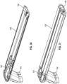
- FIG. IB shows a perspective view of one end of the roof rack system 100
- FIG. 1C shows a perspective view of the other end of the roof rack system 100.
- the stanchions may be coupled to the crossbar in any suitable arrangement (e.g., rigidly coupled, coupled by a swivel joint, coupled by a slide joint, a slip-on interface, a fastened interface, or the stanchions and respective outer pieces may be integrated as a single component).
- the stanchions include an interface 106 for mounting to the vehicle (e.g., a plug-port interface, a latching mechanism, a fastened interface, any other suitable interface, or any combination thereof).
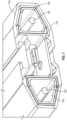
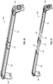
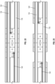
- FIGS. 2-13 show various views of an illustrative crossbar 102 in accordance with some embodiments of the present disclosure.
- the LH outer piece 108, RH 110 outer piece, and center outer piece 112 and the one or more internal bars 118 are constructed from metal.
- the one or more internal bars 118 are isolated from the outer pieces 108, 110, 112 by an intermediate material.
- the intermediate material may include nylon, rubber, or other suitable material, formed as end caps of the one or more internal bars that prevent vibration, scratching, and wear.
- the eyelet end 130 of the RH cable 124 also moves outboard, while the other end of the RH cable 124, coupled to the LH outer piece 108, also moves outboard but in the opposite direction. Similar movements take place for the LH cable 122 when the LH outer piece moves outboard. Accordingly, the center outer piece 112 remains centered. For example, a user may apply force, e.g., along the longitudinal axis of the crossbar 102, to any or all of the three outer pieces 108, 110, 112 to contract or expand the length of the crossbar.
- the pulley system 128 helps ensure the center outer piece 112 remains centered between the RH and LH outer pieces 108, 110.
- FIG. 12 shows a perspective view a center section of the crossbar, with the center outer piece 112 in place.
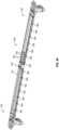
- FIG. 13 shows a perspective view of the LH pulley 138, with the LH cable 122, having an eyelet 140 configured to be coupled to the LH outer piece 108, wrapped around 180 degrees.
- the RH cable 124 is also visible in FIG. 13 .
- the LH pulley 138 e.g., the LH pulley axle, is rigidly coupled to the internal bars by a bracket 142, as illustrated.
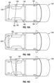
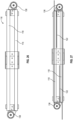
- FIGS. 14-15 show block diagrams of an illustrative crossbar 102, in accordance with some embodiments of the present disclosure.
- FIGS. 14A and 14B show two views, where the view of FIG. 14A omits the LH cable 122 and the view of FIG. 14B omits the RH cable 124, for clarity.
- FIGS. 14A and 14B show the crossbar 102 in a fully contracted state.
- FIGS. 15A and 15B show two views of the crossbar 102 extended, where the view of FIG. 15A omits the LH cable 122 and the view of FIG. 15B omits the RH cable 124, for clarity.
- Each of the RH and LH cables' ends 134, 144 are fixed to the respective outer pieces 108, 110, and accordingly the cable ends 134, 144 move relative to the RH and LH pulleys 136, 138.
- the roof rack system 100 includes one or more locking mechanisms configured to, when locked, constrain motion of a cable, a pully, an outer piece, or a combination thereof, relative to the inner structure (e.g., the internal bars).
- the locking mechanism may include a clamp on a cable that prevents the cable from moving by applying a friction force.
- the locking mechanism may include a set screw that, when tightened, prevents a pully from rotating.
- the locking mechanism may include a clamp that, when locked, applies a friction force between an internal bar and a LH or RH outer piece to prevent relative motion.
- the internal structure may include detent positions, or otherwise provide for discretized extension lengths.
- the pulley axle may be toothed, or the internal bar may include a ratchet mechanism such that the LH and RH outer pieces achieve predetermined equilibrium positions.
- a cable may include a belt, flexible rod, a wire, a toothed belt, any other suitable flexible component, or combination thereof, that may undergo tension.
- a pulley may include a grooved pulley, a toothed pulley (e.g., a sprocket or gear), a multi-channel pulley, or a cylindrical pulley, any other suitable rotational member, or any combination thereof.
- the center outer piece 112 is centered, e.g., longitudinally centered, on the crossbar 112 and is configured to remain centered.
- some mounting accessories may be required to be attached to a LH or RH outer piece 108, 110 (e.g., a T-slot 114 thereof) and the center section 126 (e.g., a T-slot 114 thereof) of the roof rack system 110.
- the LH or RH outer pieces 108, 110 may be relatively longer than the other.
- the RH and LH outer pieces 108, 110 may move by an equivalent amount in respective directions relative to the center outer piece 112, but the center outer piece 112 is not centered along the crossbar 102, e.g., the center outer piece 112 not being centered about the transverse midplane of the crossbar 102.
- this arrangement may be desired to create a longer section of T-slot 114 in one of the LH or RH outer pieces 108, 110, and a shorter section of T-slot 114 in the other.
- the roof rack system 100 may be, in some embodiments, reversible in the side-to- side direction so that the long and short pieces may be on either side of the center outer piece 112 (e.g., the roof rack 100, or the cross bar 102, can be flipped left to right).
- This arrangement may be useful to accommodate a range of accessory widths and shapes.
- Accessories may include for example, kayaks, storage containers, surfboards, canoes, skis, snowboards, bikes or bike racks, cargo bed covers, any other suitable equipment, or any combination thereof.
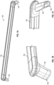
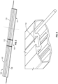
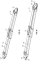
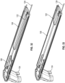
- FIGS. 17-33 show various views and states of an illustrative roof rack 100, in accordance with some embodiments of the present disclosure.
- FIG. 18 shows a top perspective view of the illustrative roof rack 100 in a partially extended state, in accordance with some embodiments of the present disclosure.
- FIG. 19 shows a top perspective view of the illustrative roof rack 100 in a fully extended state, in accordance with some embodiments of the present disclosure.
- FIG. 21 shows a perspective view of the illustrative roof rack 100 in a fully extended state, in accordance with some embodiments of the present disclosure.
- 25 A to 25D illustrate how the end 134 of the RH cable 124 is fixed, e.g., directly or indirectly, to the outboard end 152 of the first section 107, e.g., at a point on the LH stanchion 104, and how the end 154 of the LH cable 122 is fixed, e.g., directly or indirectly, to the inboard end 156 of the first section 107, e.g., at a point on end plate 158.
- FIG. 29 shows a perspective view of the illustrative internal structure of the roof rack 100, with the LH and RH cables 122, 124, in accordance with some embodiments of the present disclosure.
- FIG. 31 shows a perspective view of the illustrative LH outer piece 108 and corresponding stanchion 104, in accordance with some embodiments of the present disclosure.
- FIG. 31 also shows a tie down 161 configured to provide a feature to affix a cable or other securement for securing equipment to the roof rack 100.
- the bracket 160 prevents relative motion between the stanchion 104 and the LH outer piece 108.
- a similar arrangement may be included for the RH outer piece 110 and corresponding stanchion 104.
- FIG. 34 shows a perspective cross-sectional view of an illustrative roof rack 200. Similar to roof rack 100, roof rack 200 comprises a first section 107 and a second section 109, which are configured to receive the internal bars 118. However, roof rack 200 does not include a pulley cable mechanism. The internal bars 118 of roof rack 200 are free to slide through at least one of the first section 107 and the second section 109.
- the roof rack 200 may comprise at least one bushing 163, e g., a sleeve bearing, configured to constrain off-axis movement of the internal bars 118, e g., movement of the internal bars 118 in a direction perpendicular to the axis of motion, whilst allowing the internal bars 118 to slide freely along the axis of motion.
- the bushing 163 may be configured to constrain the rotational motion of the internal bars 118, e.g., the rotation of the internal bars 118 around the axis of motion.
- roof rack 100 similar to roof rack 200, may comprise at least one bushing similar to bushing 163.
- the internal bars 118 may be fixed relative to each of the first section 107 and the second section 109 by virtue of detent features 162 in the internal bars 118 configured to interact with detent feature 164 on each of the first section 107 and the second section 109.
- the detent features 162 in the internal bars 118 and the detent feature 164 on each of the first section 107 and the second section 109 may comprise a series of openings configured to receive a locking pin. In this way, the length of the crossbar assembly 102 may be adjusted by aligning the desired detent features 162 in the internal bars 118 and the detent feature 164 on each of the first section 107 and the second section 109.
Landscapes
- Engineering & Computer Science (AREA)
- Mechanical Engineering (AREA)
- Fittings On The Vehicle Exterior For Carrying Loads, And Devices For Holding Or Mounting Articles (AREA)
Claims (14)
- Dachträgersystem (100, 200) zum Befestigen an einem Fahrzeug mit einer Vielzahl von Montagestellen, wobei das Dachträgersystem umfasst:
eine Querstangenbaugruppe (102), umfassend:eine Bewegungsachse;eine innere Struktur;einen ersten Abschnitt (107), der dazu konfiguriert ist, sich relativ zu der inneren Struktur entlang der Achse zu verschieben,einen zweiten Abschnitt (111), der dazu konfiguriert ist, sich relativ zu der inneren Struktur gegenüber des ersten Abschnitts entlang der Achse zu verschieben, undeinen dritten Abschnitt (109), der starr an der inneren Struktur befestigt und zwischen dem ersten Abschnitt und dem zweiten Abschnitt angeordnet ist, wobei die innere Struktur umfasst:mindestens eine Innenstange (118), die dazu konfiguriert ist, die Querstangenbaugruppe (102) zu stützen; undmindestens einen Gleitmechanismus, der dazu konfiguriert ist, es dem ersten Abschnitt (107) und dem zweiten Abschnitt (111) zu ermöglichen, sich relativ zu der mindestens einen Innenstange zu verschieben; wobei der Gleitmechanismus dazu konfiguriert ist, zu bewirken, dass der dritte Abschnitt selbstzentrierend ist, sodass der dritte Abschnitt zwischen dem ersten Abschnitt und dem zweiten Abschnitt zentriert bleibt, wenn sich der erste Abschnitt und der zweite Abschnitt verschieben;eine erste Endhalterung (104), die mit einem äußeren Teil des ersten Abschnitts verbunden und dazu konfiguriert ist, an einer ersten Montagestelle montiert zu werden; undeine zweite Endhalterung (104), die mit einem äußeren Teil des zweiten Abschnitts verbunden und dazu konfiguriert ist, an einer zweiten Montagestelle montiert zu werden. - Dachträgersystem (100, 200) nach Anspruch 1, wobei die mindestens eine Innenstange (118) einen hohlen Innenraum aufweist.
- Dachträgersystem (100) nach Anspruch 1, wobei der mindestens eine Gleitmechanismus einen Seilzugmechanismus (128) umfasst.
- Dachträgersystem (100) nach Anspruch 3, wobei der Seilzugmechanismus (128) Folgendes umfasst:eine Rolle (136, 138), die starr an der mindestens einen Innenstange (118) befestigt ist;ein Seil (122, 124), das ein erstes Seilende (130, 144) und ein zweites Seilende (134, 154) umfasst, wobei:das erste Seilende an dem ersten Abschnitt (107) befestigt ist,das zweite Seilende an dem zweiten Abschnitt (111) befestigt ist, unddas Seil um die Rolle (136, 138) gewickelt ist.
- Dachträgersystem (100) nach Anspruch 4, wobei die Rolle (136, 138) durch eine Achse starr an der mindestens einen Innenstange (118) befestigt ist.
- Dachträgersystem (100) nach Anspruch 3, wobei der erste Abschnitt (107) auf einer ersten Seite des dritten Abschnitts (109) positioniert ist, und wobei der Seilzugmechanismus (128) umfasst:eine erste Rolle (136), die starr an der mindestens einen Innenstange (118) auf der ersten Seite des dritten Abschnitts befestigt ist;eine zweite Rolle (138), die an der mindestens einen Innenstange auf einer der ersten Seite gegenüberliegenden zweiten Seite des dritten Abschnitts starr befestigt ist;ein erstes Seil (122), das an dem ersten Abschnitt und dem zweiten Abschnitt befestigt ist, wobei das erste Seil um die erste Rolle (136) gewickelt ist;ein zweites Seil (124), das an dem ersten Abschnitt und dem zweiten Abschnitt befestigt ist, wobei das zweite Seil um die zweite Rolle (138) gewickelt ist.
- Dachträgersystem (200) nach Anspruch 1, wobei der mindestens eine Gleitmechanismus einen Zahnstangen- und Ritzelmechanismus umfasst, wobei eine erste Zahnstange mit dem ersten Abschnitt (107) gekoppelt ist, eine zweite Zahnstange mit dem zweiten Abschnitt (111) gekoppelt ist und ein Ritzel mit der inneren Struktur gekoppelt ist.
- Dachträgersystem (100, 200) nach Anspruch 1, wobei der erste Abschnitt (107), der zweite Abschnitt (111) und der dritte Abschnitt (109) jeweils ein ähnliches Außenprofil aufweisen.
- Dachträgersystem (100, 200) nach Anspruch 8, wobei das Außenprofil ein aerodynamisches Merkmal aufweist.
- Dachträgersystem (100, 200) nach Anspruch 1, wobei die innere Struktur durch ein Zwischenmaterial sowohl mit dem ersten Abschnitt (107) als auch mit dem zweiten Abschnitt (111) verbunden ist und wobei das Zwischenmaterial optional mindestens eines von Gummi und Kunststoff umfasst.
- Dachträgersystem (100, 200) nach Anspruch 1, ferner umfassend einen ersten Verriegelungsmechanismus, der dazu konfiguriert ist, den ersten Abschnitt (107) an der inneren Struktur zu verriegeln, und optional einen zweiten Verriegelungsmechanismus, der dazu konfiguriert ist, den zweiten Abschnitt (111) an der inneren Struktur zu verriegeln.
- Verfahren zum Installieren eines Dachträgersystems (100, 200) nach einem der vorhergehenden Ansprüche an einem Fahrzeug, wobei das Verfahren umfasst:Befestigen der ersten Endhalterung (104) an einer ersten Montagestelle des Fahrzeugs;Ändern der Länge der ausziehbaren Querstange durch Aufbringen einer Kraft; undBefestigen der zweiten Endhalterung (104) an einer zweiten Montagestelle des Fahrzeugs.
- Verfahren nach Anspruch 12, wobei:die ausziehbare Querstange einen rechtsseitigen Abschnitt (107), einen mittleren Abschnitt (109) und einem linksseitigen Abschnitt (111) umfasst;sich die Querstange entlang einer Achse erstreckt;der dritte Abschnitt entlang der Achse zentriert ist; undwenn die Länge der verlängerten Querstange verändert wird, der dritte Abschnitt zentriert bleibt.
- Verfahren nach Anspruch 13, wobei das Ändern der Länge der ausziehbaren Querstange Ausüben einer Kraft auf mindestens einen von dem ersten Abschnitt (107), dem zweiten Abschnitt (111) und dem dritten Abschnitt (109) umfasst.
Applications Claiming Priority (2)
| Application Number | Priority Date | Filing Date | Title |
|---|---|---|---|
| US201862766600P | 2018-11-13 | 2018-11-13 | |
| PCT/US2019/060803 WO2020102118A1 (en) | 2018-11-13 | 2019-11-11 | Extendable crossbar for a vehicle |
Publications (2)
| Publication Number | Publication Date |
|---|---|
| EP3856572A1 EP3856572A1 (de) | 2021-08-04 |
| EP3856572B1 true EP3856572B1 (de) | 2024-07-03 |
Family
ID=68835296
Family Applications (1)
| Application Number | Title | Priority Date | Filing Date |
|---|---|---|---|
| EP19817462.5A Active EP3856572B1 (de) | 2018-11-13 | 2019-11-11 | Ausziehbare querstange für ein fahrzeug |
Country Status (5)
| Country | Link |
|---|---|
| US (2) | US11027661B2 (de) |
| EP (1) | EP3856572B1 (de) |
| CN (2) | CN120171431A (de) |
| CA (1) | CA3112605A1 (de) |
| WO (1) | WO2020102118A1 (de) |
Families Citing this family (20)
| Publication number | Priority date | Publication date | Assignee | Title |
|---|---|---|---|---|
| US10414322B1 (en) | 2016-04-12 | 2019-09-17 | Jason Coulter | Trailer and housing system |
| EP3339101B1 (de) * | 2016-12-20 | 2019-02-20 | Thule Sweden AB | Fahrzeuglastträger |
| EP3602534A4 (de) | 2017-03-24 | 2021-01-13 | Manufacturing Resources International, Inc. | Dachmontagevorrichtung und system für fahrzeugdachträger |
| AU201712995S (en) * | 2017-05-17 | 2017-05-29 | Aluminium Industries Invest Pty Ltd | An extrusion |
| EP3415370B1 (de) * | 2017-06-12 | 2020-01-15 | Thule Sweden AB | Lastenträger |
| USD869378S1 (en) * | 2018-03-23 | 2019-12-10 | Manufacturing Resources International, Inc. | Roof bar |
| EP3594065B1 (de) * | 2018-07-13 | 2020-11-04 | Thule Sweden AB | Lastenträger |
| US11230326B2 (en) * | 2018-11-13 | 2022-01-25 | Rivian Ip Holdings, Llc | Vehicle accessory port and plug |
| US10870453B2 (en) | 2018-11-13 | 2020-12-22 | Rivian Ip Holdings, Llc | Vehicle accessory port and plug |
| USD929930S1 (en) * | 2019-04-18 | 2021-09-07 | Hyundai Mobis Co., Ltd. | Roof cross bar for vehicle |
| US11285895B2 (en) | 2019-08-27 | 2022-03-29 | Manufacturing Resources International, Inc. | Solar powered vehicle mounted display |
| US11496091B2 (en) | 2019-08-27 | 2022-11-08 | Manufacturing Resources International, Inc. | Electronic display assemblies with solar panels |
| EP3858678B1 (de) * | 2020-01-30 | 2022-03-09 | Thule Sweden AB | Querträger und kupplungselement für einen querträger |
| WO2021217198A1 (en) * | 2020-04-29 | 2021-11-04 | Rhino Rack Australia Pty Limited | Extendable guard rail for a cargo platform |
| USD1018429S1 (en) * | 2020-06-16 | 2024-03-19 | Hongzhou SWEET I&E CO., LTD. | RV screen door cross bar handle |
| USD1007400S1 (en) * | 2022-11-10 | 2023-12-12 | Changzhou Chunlai Auto Parts Trading Co., Ltd | Car roof rack cross bar |
| CN115675298A (zh) | 2022-11-21 | 2023-02-03 | 宁波品川汽车配件有限公司 | 带锁车顶横杆 |
| US20250001925A1 (en) * | 2023-06-29 | 2025-01-02 | Rivian Ip Holdings, Llc | Accessory mount |
| USD1051021S1 (en) * | 2024-07-08 | 2024-11-12 | Chunyan Ye | Automotive crossbar |
| USD1055837S1 (en) * | 2024-08-07 | 2024-12-31 | Foshan Haorunda Auto Products Co., Ltd | Crossbar for car |
Family Cites Families (31)
| Publication number | Priority date | Publication date | Assignee | Title |
|---|---|---|---|---|
| FR1205062A (fr) * | 1957-11-02 | 1960-01-29 | Porte-bagages pour automobile | |
| US2983414A (en) * | 1957-12-27 | 1961-05-09 | Fehr Eugen | Ski-carrier for releasable fastening on the roof of a motorcar |
| US3385488A (en) * | 1967-03-31 | 1968-05-28 | Bronson Joseph | Clamping device |
| US3495750A (en) * | 1968-02-27 | 1970-02-17 | Casimiro Milheiro Oliveira | Luggage rack |
| US4101061A (en) * | 1977-05-09 | 1978-07-18 | U-Haul International, Inc. | Adjustable car top carrier support |
| DE3011641A1 (de) * | 1980-03-26 | 1981-10-01 | Hiller Vertriebs-GmbH für Fahrzeugteile, 7634 Kippenheim | Quertraeger zum verbinden von zwei auf einem fahrzeug o.dgl. angeordneten holmen o.dgl. |
| US4354625A (en) * | 1981-04-06 | 1982-10-19 | U-Haul International, Inc. | Car top carrier |
| SE436633B (sv) * | 1982-04-21 | 1985-01-14 | Thule Ind Ab | Lasthallare for fordon |
| SE450561B (sv) * | 1983-06-20 | 1987-07-06 | Saab Scania Ab | Lastbygel for fordon |
| US4489868A (en) * | 1984-01-09 | 1984-12-25 | L. B. Industries, Inc. | Luggage rack |
| US4757929A (en) * | 1987-09-01 | 1988-07-19 | Norman Nelson | Car rack |
| US5009337A (en) * | 1989-05-01 | 1991-04-23 | Domenico Bimbi | Automotive parts support rack |
| US5226570A (en) * | 1991-07-16 | 1993-07-13 | Fabio Pedrini | Self-centering roof rack |
| US6131781A (en) * | 1996-11-18 | 2000-10-17 | Industri Ab Thule | Equipment load assist to roof rack |
| CA2218007A1 (en) * | 1997-10-10 | 1999-04-10 | Sportrack International Inc. | Adjustable load-carrying rack for vehicles |
| US6079741A (en) * | 1998-04-24 | 2000-06-27 | Maver; Ryan D. | Vehicle bed ballast apparatus |
| US6015074A (en) * | 1998-07-01 | 2000-01-18 | Snavely; Travis J. | Roof rack for a vehicle |
| FR2799706B1 (fr) * | 1999-10-19 | 2002-01-11 | Scambia Ind Dev Ag | Porte-charge pour un vehicule automobile ainsi que vehicule automobile avec une porte-charge |
| FR2816564B1 (fr) | 2000-11-14 | 2003-02-28 | Wagon Automotive Snc | Barre de galerie pour vehicules automobiles, destinee a etre montee sur des longerons non paralleles |
| KR200402088Y1 (ko) | 2005-09-07 | 2005-11-25 | 주식회사 엘지화학 | 차량용 루프 캐리어의 크로스바 고정장치 |
| TWI433789B (zh) * | 2011-07-05 | 2014-04-11 | Beto Engineering & Marketing | Roofing device |
| SE1230115A1 (sv) * | 2012-02-04 | 2013-08-05 | Henrik Sverkersson | Justerbart takräcke med nedsänkta bärelement |
| DE102015108555A1 (de) * | 2014-08-12 | 2016-02-18 | Westfalia-Automotive Gmbh | Fahrradträger |
| EP3031669B1 (de) * | 2014-12-12 | 2018-01-31 | Thule Sweden AB | Dachträgerkit und Laststreifen für eine lasttragende Stange |
| DE102015001804A1 (de) * | 2015-02-11 | 2016-08-11 | GM Global Technology Operations LLC (n. d. Ges. d. Staates Delaware) | Lastenträger zur Anordnung am Heck eines Kraftfahrzeugs |
| CN204547948U (zh) * | 2015-04-28 | 2015-08-12 | 长城汽车股份有限公司 | 一种汽车及其车顶行李架和车顶行李架装置 |
| US10040490B2 (en) * | 2016-07-25 | 2018-08-07 | GM Global Technology Operations LLC | Cargo system for a vehicle |
| AU2017101232B4 (en) * | 2017-02-21 | 2018-01-18 | Norman BOYLE | Roof rack |
| CN107364399A (zh) * | 2017-08-07 | 2017-11-21 | 深圳宏智自动车衣有限公司 | 一种可伸缩的汽车行李架 |
| US11447074B2 (en) * | 2018-08-21 | 2022-09-20 | Noah MALGERI | Laterally extensible accessible vehicle cargo rack |
| US10625684B1 (en) * | 2019-02-14 | 2020-04-21 | George J. Schafer, JR. | Weight distributing cargo rack system for use on vehicles |
-
2019
- 2019-11-11 EP EP19817462.5A patent/EP3856572B1/de active Active
- 2019-11-11 US US16/680,438 patent/US11027661B2/en active Active
- 2019-11-11 CN CN202510557014.1A patent/CN120171431A/zh active Pending
- 2019-11-11 CN CN201980067889.6A patent/CN112912279B/zh active Active
- 2019-11-11 WO PCT/US2019/060803 patent/WO2020102118A1/en not_active Ceased
- 2019-11-11 CA CA3112605A patent/CA3112605A1/en active Pending
-
2021
- 2021-05-14 US US17/321,039 patent/US12083999B2/en active Active
Also Published As
| Publication number | Publication date |
|---|---|
| EP3856572A1 (de) | 2021-08-04 |
| CN112912279A (zh) | 2021-06-04 |
| US20210268967A1 (en) | 2021-09-02 |
| CN112912279B (zh) | 2025-05-06 |
| CA3112605A1 (en) | 2020-05-22 |
| CN120171431A (zh) | 2025-06-20 |
| US20200148126A1 (en) | 2020-05-14 |
| US11027661B2 (en) | 2021-06-08 |
| WO2020102118A1 (en) | 2020-05-22 |
| US12083999B2 (en) | 2024-09-10 |
Similar Documents
| Publication | Publication Date | Title |
|---|---|---|
| US12083999B2 (en) | Extendable crossbar for a vehicle | |
| US7806307B2 (en) | Carrier device for a bicycle | |
| US8167180B2 (en) | Lean support for elongate articles on a load carrier | |
| JP6535091B2 (ja) | 車両の支持構造体にワイヤーハーネスを取り付ける自己締結ブラケット、及び、これを備えた車両 | |
| KR102320389B1 (ko) | 조정 가능한 하중 지지부 | |
| US20080193265A1 (en) | Vehicle boat loading device | |
| EP2172368B1 (de) | System und Verfahren für Fahrzeugartikelträger mit verstaubaren Querträgern | |
| JP5883934B2 (ja) | 荷台脚および荷台脚を備えた自動車のルーフ用荷物運搬ラック | |
| SE463143B (sv) | Skidboxfaeste | |
| CA2728776A1 (en) | Coordinated adjustable trunk rack for carrying bicycles | |
| WO2013166064A2 (en) | Adjustable boat carrier | |
| KR20180035783A (ko) | 하중 운반체용 지지 패드 | |
| US8297896B2 (en) | Holding device and holding apparatus for a cargo space of a motor vehicle | |
| KR20120094917A (ko) | 차량용 진공 장착식 캐리어 | |
| WO2013022749A1 (en) | Cargo accessory modular adapter | |
| CN103269909A (zh) | 托架安装件、该托架安装件的锁定机构和相应的装配方法 | |
| JP2017512706A5 (de) | ||
| US20220250552A1 (en) | Surfboard carrier | |
| US20060273123A1 (en) | Rack tower assemblies and rack systems | |
| SE450561B (sv) | Lastbygel for fordon | |
| EP2383151B1 (de) | Ausziehbare Fahrzeuggepäckträgeranordnung | |
| US20060237500A1 (en) | Side rail rack with removable base | |
| EP3837141B1 (de) | Anordnung für eine lasttragende struktur für ein fahrzeug | |
| US20050199665A1 (en) | Roof-top carrier | |
| WO2000076808A1 (en) | Device for securing a load bearing element |
Legal Events
| Date | Code | Title | Description |
|---|---|---|---|
| STAA | Information on the status of an ep patent application or granted ep patent |
Free format text: STATUS: UNKNOWN |
|
| STAA | Information on the status of an ep patent application or granted ep patent |
Free format text: STATUS: THE INTERNATIONAL PUBLICATION HAS BEEN MADE |
|
| PUAI | Public reference made under article 153(3) epc to a published international application that has entered the european phase |
Free format text: ORIGINAL CODE: 0009012 |
|
| STAA | Information on the status of an ep patent application or granted ep patent |
Free format text: STATUS: REQUEST FOR EXAMINATION WAS MADE |
|
| 17P | Request for examination filed |
Effective date: 20210427 |
|
| AK | Designated contracting states |
Kind code of ref document: A1 Designated state(s): AL AT BE BG CH CY CZ DE DK EE ES FI FR GB GR HR HU IE IS IT LI LT LU LV MC MK MT NL NO PL PT RO RS SE SI SK SM TR |
|
| DAV | Request for validation of the european patent (deleted) | ||
| DAX | Request for extension of the european patent (deleted) | ||
| STAA | Information on the status of an ep patent application or granted ep patent |
Free format text: STATUS: EXAMINATION IS IN PROGRESS |
|
| 17Q | First examination report despatched |
Effective date: 20221020 |
|
| GRAP | Despatch of communication of intention to grant a patent |
Free format text: ORIGINAL CODE: EPIDOSNIGR1 |
|
| STAA | Information on the status of an ep patent application or granted ep patent |
Free format text: STATUS: GRANT OF PATENT IS INTENDED |
|
| INTG | Intention to grant announced |
Effective date: 20240319 |
|
| GRAS | Grant fee paid |
Free format text: ORIGINAL CODE: EPIDOSNIGR3 |
|
| GRAA | (expected) grant |
Free format text: ORIGINAL CODE: 0009210 |
|
| STAA | Information on the status of an ep patent application or granted ep patent |
Free format text: STATUS: THE PATENT HAS BEEN GRANTED |
|
| AK | Designated contracting states |
Kind code of ref document: B1 Designated state(s): AL AT BE BG CH CY CZ DE DK EE ES FI FR GB GR HR HU IE IS IT LI LT LU LV MC MK MT NL NO PL PT RO RS SE SI SK SM TR |
|
| REG | Reference to a national code |
Ref country code: CH Ref legal event code: EP |
|
| REG | Reference to a national code |
Ref country code: DE Ref legal event code: R096 Ref document number: 602019054704 Country of ref document: DE |
|
| REG | Reference to a national code |
Ref country code: LT Ref legal event code: MG9D |
|
| REG | Reference to a national code |
Ref country code: NL Ref legal event code: MP Effective date: 20240703 |
|
| PG25 | Lapsed in a contracting state [announced via postgrant information from national office to epo] |
Ref country code: PT Free format text: LAPSE BECAUSE OF FAILURE TO SUBMIT A TRANSLATION OF THE DESCRIPTION OR TO PAY THE FEE WITHIN THE PRESCRIBED TIME-LIMIT Effective date: 20241104 |
|
| REG | Reference to a national code |
Ref country code: AT Ref legal event code: MK05 Ref document number: 1699511 Country of ref document: AT Kind code of ref document: T Effective date: 20240703 |
|
| PG25 | Lapsed in a contracting state [announced via postgrant information from national office to epo] |
Ref country code: NL Free format text: LAPSE BECAUSE OF FAILURE TO SUBMIT A TRANSLATION OF THE DESCRIPTION OR TO PAY THE FEE WITHIN THE PRESCRIBED TIME-LIMIT Effective date: 20240703 |
|
| PG25 | Lapsed in a contracting state [announced via postgrant information from national office to epo] |
Ref country code: PT Free format text: LAPSE BECAUSE OF FAILURE TO SUBMIT A TRANSLATION OF THE DESCRIPTION OR TO PAY THE FEE WITHIN THE PRESCRIBED TIME-LIMIT Effective date: 20241104 Ref country code: NL Free format text: LAPSE BECAUSE OF FAILURE TO SUBMIT A TRANSLATION OF THE DESCRIPTION OR TO PAY THE FEE WITHIN THE PRESCRIBED TIME-LIMIT Effective date: 20240703 |
|
| PG25 | Lapsed in a contracting state [announced via postgrant information from national office to epo] |
Ref country code: NO Free format text: LAPSE BECAUSE OF FAILURE TO SUBMIT A TRANSLATION OF THE DESCRIPTION OR TO PAY THE FEE WITHIN THE PRESCRIBED TIME-LIMIT Effective date: 20241003 |
|
| PG25 | Lapsed in a contracting state [announced via postgrant information from national office to epo] |
Ref country code: FI Free format text: LAPSE BECAUSE OF FAILURE TO SUBMIT A TRANSLATION OF THE DESCRIPTION OR TO PAY THE FEE WITHIN THE PRESCRIBED TIME-LIMIT Effective date: 20240703 Ref country code: GR Free format text: LAPSE BECAUSE OF FAILURE TO SUBMIT A TRANSLATION OF THE DESCRIPTION OR TO PAY THE FEE WITHIN THE PRESCRIBED TIME-LIMIT Effective date: 20241004 Ref country code: PL Free format text: LAPSE BECAUSE OF FAILURE TO SUBMIT A TRANSLATION OF THE DESCRIPTION OR TO PAY THE FEE WITHIN THE PRESCRIBED TIME-LIMIT Effective date: 20240703 |
|
| PG25 | Lapsed in a contracting state [announced via postgrant information from national office to epo] |
Ref country code: BG Free format text: LAPSE BECAUSE OF FAILURE TO SUBMIT A TRANSLATION OF THE DESCRIPTION OR TO PAY THE FEE WITHIN THE PRESCRIBED TIME-LIMIT Effective date: 20240703 |
|
| PG25 | Lapsed in a contracting state [announced via postgrant information from national office to epo] |
Ref country code: LV Free format text: LAPSE BECAUSE OF FAILURE TO SUBMIT A TRANSLATION OF THE DESCRIPTION OR TO PAY THE FEE WITHIN THE PRESCRIBED TIME-LIMIT Effective date: 20240703 |
|
| PG25 | Lapsed in a contracting state [announced via postgrant information from national office to epo] |
Ref country code: IS Free format text: LAPSE BECAUSE OF FAILURE TO SUBMIT A TRANSLATION OF THE DESCRIPTION OR TO PAY THE FEE WITHIN THE PRESCRIBED TIME-LIMIT Effective date: 20241103 Ref country code: AT Free format text: LAPSE BECAUSE OF FAILURE TO SUBMIT A TRANSLATION OF THE DESCRIPTION OR TO PAY THE FEE WITHIN THE PRESCRIBED TIME-LIMIT Effective date: 20240703 |
|
| PG25 | Lapsed in a contracting state [announced via postgrant information from national office to epo] |
Ref country code: HR Free format text: LAPSE BECAUSE OF FAILURE TO SUBMIT A TRANSLATION OF THE DESCRIPTION OR TO PAY THE FEE WITHIN THE PRESCRIBED TIME-LIMIT Effective date: 20240703 Ref country code: CZ Free format text: LAPSE BECAUSE OF FAILURE TO SUBMIT A TRANSLATION OF THE DESCRIPTION OR TO PAY THE FEE WITHIN THE PRESCRIBED TIME-LIMIT Effective date: 20240703 |
|
| PG25 | Lapsed in a contracting state [announced via postgrant information from national office to epo] |
Ref country code: ES Free format text: LAPSE BECAUSE OF FAILURE TO SUBMIT A TRANSLATION OF THE DESCRIPTION OR TO PAY THE FEE WITHIN THE PRESCRIBED TIME-LIMIT Effective date: 20240703 Ref country code: RS Free format text: LAPSE BECAUSE OF FAILURE TO SUBMIT A TRANSLATION OF THE DESCRIPTION OR TO PAY THE FEE WITHIN THE PRESCRIBED TIME-LIMIT Effective date: 20241003 |
|
| PG25 | Lapsed in a contracting state [announced via postgrant information from national office to epo] |
Ref country code: RS Free format text: LAPSE BECAUSE OF FAILURE TO SUBMIT A TRANSLATION OF THE DESCRIPTION OR TO PAY THE FEE WITHIN THE PRESCRIBED TIME-LIMIT Effective date: 20241003 Ref country code: PL Free format text: LAPSE BECAUSE OF FAILURE TO SUBMIT A TRANSLATION OF THE DESCRIPTION OR TO PAY THE FEE WITHIN THE PRESCRIBED TIME-LIMIT Effective date: 20240703 Ref country code: NO Free format text: LAPSE BECAUSE OF FAILURE TO SUBMIT A TRANSLATION OF THE DESCRIPTION OR TO PAY THE FEE WITHIN THE PRESCRIBED TIME-LIMIT Effective date: 20241003 Ref country code: LV Free format text: LAPSE BECAUSE OF FAILURE TO SUBMIT A TRANSLATION OF THE DESCRIPTION OR TO PAY THE FEE WITHIN THE PRESCRIBED TIME-LIMIT Effective date: 20240703 Ref country code: IS Free format text: LAPSE BECAUSE OF FAILURE TO SUBMIT A TRANSLATION OF THE DESCRIPTION OR TO PAY THE FEE WITHIN THE PRESCRIBED TIME-LIMIT Effective date: 20241103 Ref country code: HR Free format text: LAPSE BECAUSE OF FAILURE TO SUBMIT A TRANSLATION OF THE DESCRIPTION OR TO PAY THE FEE WITHIN THE PRESCRIBED TIME-LIMIT Effective date: 20240703 Ref country code: GR Free format text: LAPSE BECAUSE OF FAILURE TO SUBMIT A TRANSLATION OF THE DESCRIPTION OR TO PAY THE FEE WITHIN THE PRESCRIBED TIME-LIMIT Effective date: 20241004 Ref country code: FI Free format text: LAPSE BECAUSE OF FAILURE TO SUBMIT A TRANSLATION OF THE DESCRIPTION OR TO PAY THE FEE WITHIN THE PRESCRIBED TIME-LIMIT Effective date: 20240703 Ref country code: ES Free format text: LAPSE BECAUSE OF FAILURE TO SUBMIT A TRANSLATION OF THE DESCRIPTION OR TO PAY THE FEE WITHIN THE PRESCRIBED TIME-LIMIT Effective date: 20240703 Ref country code: CZ Free format text: LAPSE BECAUSE OF FAILURE TO SUBMIT A TRANSLATION OF THE DESCRIPTION OR TO PAY THE FEE WITHIN THE PRESCRIBED TIME-LIMIT Effective date: 20240703 Ref country code: BG Free format text: LAPSE BECAUSE OF FAILURE TO SUBMIT A TRANSLATION OF THE DESCRIPTION OR TO PAY THE FEE WITHIN THE PRESCRIBED TIME-LIMIT Effective date: 20240703 Ref country code: AT Free format text: LAPSE BECAUSE OF FAILURE TO SUBMIT A TRANSLATION OF THE DESCRIPTION OR TO PAY THE FEE WITHIN THE PRESCRIBED TIME-LIMIT Effective date: 20240703 |
|
| REG | Reference to a national code |
Ref country code: DE Ref legal event code: R097 Ref document number: 602019054704 Country of ref document: DE |
|
| PG25 | Lapsed in a contracting state [announced via postgrant information from national office to epo] |
Ref country code: DK Free format text: LAPSE BECAUSE OF FAILURE TO SUBMIT A TRANSLATION OF THE DESCRIPTION OR TO PAY THE FEE WITHIN THE PRESCRIBED TIME-LIMIT Effective date: 20240703 Ref country code: RO Free format text: LAPSE BECAUSE OF FAILURE TO SUBMIT A TRANSLATION OF THE DESCRIPTION OR TO PAY THE FEE WITHIN THE PRESCRIBED TIME-LIMIT Effective date: 20240703 Ref country code: SM Free format text: LAPSE BECAUSE OF FAILURE TO SUBMIT A TRANSLATION OF THE DESCRIPTION OR TO PAY THE FEE WITHIN THE PRESCRIBED TIME-LIMIT Effective date: 20240703 |
|
| PG25 | Lapsed in a contracting state [announced via postgrant information from national office to epo] |
Ref country code: EE Free format text: LAPSE BECAUSE OF FAILURE TO SUBMIT A TRANSLATION OF THE DESCRIPTION OR TO PAY THE FEE WITHIN THE PRESCRIBED TIME-LIMIT Effective date: 20240703 |
|
| PG25 | Lapsed in a contracting state [announced via postgrant information from national office to epo] |
Ref country code: SK Free format text: LAPSE BECAUSE OF FAILURE TO SUBMIT A TRANSLATION OF THE DESCRIPTION OR TO PAY THE FEE WITHIN THE PRESCRIBED TIME-LIMIT Effective date: 20240703 Ref country code: IT Free format text: LAPSE BECAUSE OF FAILURE TO SUBMIT A TRANSLATION OF THE DESCRIPTION OR TO PAY THE FEE WITHIN THE PRESCRIBED TIME-LIMIT Effective date: 20240703 |
|
| PLBE | No opposition filed within time limit |
Free format text: ORIGINAL CODE: 0009261 |
|
| STAA | Information on the status of an ep patent application or granted ep patent |
Free format text: STATUS: NO OPPOSITION FILED WITHIN TIME LIMIT |
|
| 26N | No opposition filed |
Effective date: 20250404 |
|
| REG | Reference to a national code |
Ref country code: CH Ref legal event code: PL |
|
| PG25 | Lapsed in a contracting state [announced via postgrant information from national office to epo] |
Ref country code: MC Free format text: LAPSE BECAUSE OF FAILURE TO SUBMIT A TRANSLATION OF THE DESCRIPTION OR TO PAY THE FEE WITHIN THE PRESCRIBED TIME-LIMIT Effective date: 20240703 |
|
| PG25 | Lapsed in a contracting state [announced via postgrant information from national office to epo] |
Ref country code: LU Free format text: LAPSE BECAUSE OF NON-PAYMENT OF DUE FEES Effective date: 20241111 |
|
| REG | Reference to a national code |
Ref country code: CH Ref legal event code: PL |
|
| PG25 | Lapsed in a contracting state [announced via postgrant information from national office to epo] |
Ref country code: CH Free format text: LAPSE BECAUSE OF NON-PAYMENT OF DUE FEES Effective date: 20241130 |
|
| REG | Reference to a national code |
Ref country code: BE Ref legal event code: MM Effective date: 20241130 |
|
| PG25 | Lapsed in a contracting state [announced via postgrant information from national office to epo] |
Ref country code: SE Free format text: LAPSE BECAUSE OF FAILURE TO SUBMIT A TRANSLATION OF THE DESCRIPTION OR TO PAY THE FEE WITHIN THE PRESCRIBED TIME-LIMIT Effective date: 20240703 |
|
| PG25 | Lapsed in a contracting state [announced via postgrant information from national office to epo] |
Ref country code: BE Free format text: LAPSE BECAUSE OF NON-PAYMENT OF DUE FEES Effective date: 20241130 |
|
| PG25 | Lapsed in a contracting state [announced via postgrant information from national office to epo] |
Ref country code: IE Free format text: LAPSE BECAUSE OF NON-PAYMENT OF DUE FEES Effective date: 20241111 |
|
| PGFP | Annual fee paid to national office [announced via postgrant information from national office to epo] |
Ref country code: DE Payment date: 20251022 Year of fee payment: 7 |
|
| PGFP | Annual fee paid to national office [announced via postgrant information from national office to epo] |
Ref country code: GB Payment date: 20251023 Year of fee payment: 7 |
|
| PGFP | Annual fee paid to national office [announced via postgrant information from national office to epo] |
Ref country code: FR Payment date: 20251023 Year of fee payment: 7 |
|
| PG25 | Lapsed in a contracting state [announced via postgrant information from national office to epo] |
Ref country code: HU Free format text: LAPSE BECAUSE OF FAILURE TO SUBMIT A TRANSLATION OF THE DESCRIPTION OR TO PAY THE FEE WITHIN THE PRESCRIBED TIME-LIMIT; INVALID AB INITIO Effective date: 20191111 |
|
| PG25 | Lapsed in a contracting state [announced via postgrant information from national office to epo] |
Ref country code: CY Free format text: LAPSE BECAUSE OF FAILURE TO SUBMIT A TRANSLATION OF THE DESCRIPTION OR TO PAY THE FEE WITHIN THE PRESCRIBED TIME-LIMIT; INVALID AB INITIO Effective date: 20191111 |