EP3856574B1 - Plaques minéralogiques pour véhicules - Google Patents
Plaques minéralogiques pour véhicules Download PDFInfo
- Publication number
- EP3856574B1 EP3856574B1 EP19773042.7A EP19773042A EP3856574B1 EP 3856574 B1 EP3856574 B1 EP 3856574B1 EP 19773042 A EP19773042 A EP 19773042A EP 3856574 B1 EP3856574 B1 EP 3856574B1
- Authority
- EP
- European Patent Office
- Prior art keywords
- licence plate
- plate body
- license plate
- slot structure
- previous
- Prior art date
- Legal status (The legal status is an assumption and is not a legal conclusion. Google has not performed a legal analysis and makes no representation as to the accuracy of the status listed.)
- Active
Links
Images


Classifications
-
- B—PERFORMING OPERATIONS; TRANSPORTING
- B60—VEHICLES IN GENERAL
- B60R—VEHICLES, VEHICLE FITTINGS, OR VEHICLE PARTS, NOT OTHERWISE PROVIDED FOR
- B60R13/00—Elements for body-finishing, identifying, or decorating; Arrangements or adaptations for advertising purposes
- B60R13/10—Registration, licensing, or like devices
- B60R13/105—Licence- or registration plates, provided with mounting means, e.g. frames, holders, retainers, brackets
-
- B—PERFORMING OPERATIONS; TRANSPORTING
- B60—VEHICLES IN GENERAL
- B60R—VEHICLES, VEHICLE FITTINGS, OR VEHICLE PARTS, NOT OTHERWISE PROVIDED FOR
- B60R13/00—Elements for body-finishing, identifying, or decorating; Arrangements or adaptations for advertising purposes
- B60R13/10—Registration, licensing, or like devices
-
- G—PHYSICS
- G06—COMPUTING OR CALCULATING; COUNTING
- G06K—GRAPHICAL DATA READING; PRESENTATION OF DATA; RECORD CARRIERS; HANDLING RECORD CARRIERS
- G06K19/00—Record carriers for use with machines and with at least a part designed to carry digital markings
- G06K19/06—Record carriers for use with machines and with at least a part designed to carry digital markings characterised by the kind of the digital marking, e.g. shape, nature, code
- G06K19/067—Record carriers with conductive marks, printed circuits or semiconductor circuit elements, e.g. credit or identity cards also with resonating or responding marks without active components
- G06K19/07—Record carriers with conductive marks, printed circuits or semiconductor circuit elements, e.g. credit or identity cards also with resonating or responding marks without active components with integrated circuit chips
- G06K19/077—Constructional details, e.g. mounting of circuits in the carrier
- G06K19/07749—Constructional details, e.g. mounting of circuits in the carrier the record carrier being capable of non-contact communication, e.g. constructional details of the antenna of a non-contact smart card
- G06K19/07758—Constructional details, e.g. mounting of circuits in the carrier the record carrier being capable of non-contact communication, e.g. constructional details of the antenna of a non-contact smart card arrangements for adhering the record carrier to further objects or living beings, functioning as an identification tag
- G06K19/0776—Constructional details, e.g. mounting of circuits in the carrier the record carrier being capable of non-contact communication, e.g. constructional details of the antenna of a non-contact smart card arrangements for adhering the record carrier to further objects or living beings, functioning as an identification tag the adhering arrangement being a layer of adhesive, so that the record carrier can function as a sticker
-
- G—PHYSICS
- G06—COMPUTING OR CALCULATING; COUNTING
- G06K—GRAPHICAL DATA READING; PRESENTATION OF DATA; RECORD CARRIERS; HANDLING RECORD CARRIERS
- G06K19/00—Record carriers for use with machines and with at least a part designed to carry digital markings
- G06K19/06—Record carriers for use with machines and with at least a part designed to carry digital markings characterised by the kind of the digital marking, e.g. shape, nature, code
- G06K19/067—Record carriers with conductive marks, printed circuits or semiconductor circuit elements, e.g. credit or identity cards also with resonating or responding marks without active components
- G06K19/07—Record carriers with conductive marks, printed circuits or semiconductor circuit elements, e.g. credit or identity cards also with resonating or responding marks without active components with integrated circuit chips
- G06K19/077—Constructional details, e.g. mounting of circuits in the carrier
- G06K19/07749—Constructional details, e.g. mounting of circuits in the carrier the record carrier being capable of non-contact communication, e.g. constructional details of the antenna of a non-contact smart card
- G06K19/07773—Antenna details
-
- G—PHYSICS
- G09—EDUCATION; CRYPTOGRAPHY; DISPLAY; ADVERTISING; SEALS
- G09F—DISPLAYING; ADVERTISING; SIGNS; LABELS OR NAME-PLATES; SEALS
- G09F7/00—Signs, name or number plates, letters, numerals, or symbols; Panels or boards
- G09F7/18—Means for attaching signs, plates, panels, or boards to a supporting structure
-
- H—ELECTRICITY
- H01—ELECTRIC ELEMENTS
- H01Q—ANTENNAS, i.e. RADIO AERIALS
- H01Q1/00—Details of, or arrangements associated with, antennas
- H01Q1/27—Adaptation for use in or on movable bodies
- H01Q1/32—Adaptation for use in or on road or rail vehicles
- H01Q1/3208—Adaptation for use in or on road or rail vehicles characterised by the application wherein the antenna is used
- H01Q1/3233—Adaptation for use in or on road or rail vehicles characterised by the application wherein the antenna is used particular used as part of a sensor or in a security system, e.g. for automotive radar, navigation systems
-
- H—ELECTRICITY
- H01—ELECTRIC ELEMENTS
- H01Q—ANTENNAS, i.e. RADIO AERIALS
- H01Q1/00—Details of, or arrangements associated with, antennas
- H01Q1/27—Adaptation for use in or on movable bodies
- H01Q1/32—Adaptation for use in or on road or rail vehicles
- H01Q1/325—Adaptation for use in or on road or rail vehicles characterised by the location of the antenna on the vehicle
- H01Q1/3283—Adaptation for use in or on road or rail vehicles characterised by the location of the antenna on the vehicle side-mounted antennas, e.g. bumper-mounted, door-mounted
-
- H—ELECTRICITY
- H01—ELECTRIC ELEMENTS
- H01Q—ANTENNAS, i.e. RADIO AERIALS
- H01Q21/00—Antenna arrays or systems
- H01Q21/06—Arrays of individually energised antenna units similarly polarised and spaced apart
- H01Q21/061—Two dimensional planar arrays
- H01Q21/064—Two dimensional planar arrays using horn or slot aerials
-
- G—PHYSICS
- G09—EDUCATION; CRYPTOGRAPHY; DISPLAY; ADVERTISING; SEALS
- G09F—DISPLAYING; ADVERTISING; SIGNS; LABELS OR NAME-PLATES; SEALS
- G09F7/00—Signs, name or number plates, letters, numerals, or symbols; Panels or boards
- G09F7/18—Means for attaching signs, plates, panels, or boards to a supporting structure
- G09F2007/1856—Means for attaching signs, plates, panels, or boards to a supporting structure characterised by the supporting structure
- G09F2007/1865—Means for attaching signs, plates, panels, or boards to a supporting structure characterised by the supporting structure on vehicles
Definitions
- the invention relates to a license plate for a vehicle according to the preamble of claim 1.
- the license plate according to the invention is a so-called number plate that can be attached to the front and/or rear of a body or bumper of a vehicle.
- License plates of this type are often counterfeited or used for other people's vehicles.
- license plates are known that have a contactless readable data carrier. This contains relevant data about the vehicle to which the license plate belongs. This data is read using an external reader. Comparing the read data with the vehicle on which the license plate is used allows conclusions to be drawn about manipulation, especially if the license plate is assigned to another person's vehicle.
- the data carriers are coupled to a slot antenna.
- the data carrier can then be read from a greater distance using this slot antenna.
- the slot structure of the antenna is incorporated into the metal body of the license plate or into a metallized layer of the license plate.
- the positioning of the slot antenna on the license plate body limits the positioning of the conventional labeling of the license plate with letters and/or numbers or the like.
- the slot can only be accommodated in a few positions on the license plate body due to the necessary labeling of the license plate.
- Another disadvantage of the known license plates with a slot antenna is that the transmission power of the antenna is limited. Since the radiation characteristics or the dipole characteristics of the slot antenna are at least largely symmetrical, part of the emitted electromagnetic waves are radiated away from the vehicle and another part in the direction of the vehicle. This means that at least half of the transmission power is absorbed by the license plate holder or the vehicle itself and only a fraction of the total transmission power is radiated in the direction of a potential receiver.
- the invention is based on the object of creating a license plate with a data carrier and an antenna, which has an improved transmission power and at the same time there is sufficient space for the positioning of a label.
- a license plate, in particular a vehicle license plate, for solving this problem has the features of claim 1. Accordingly, it is provided that the license plate has a license plate body with at least one labeling field. A label in the form of letters and/or numbers is assigned to this labeling field. This labeling enables the vehicle or the vehicle owner to be identified for the first time. In addition, at least one contactlessly readable data carrier with an antenna is assigned to the license plate body. Further information regarding the vehicle and/or the vehicle owner can be stored on this data carrier.
- the license plate body of the license plate forms at least one cavity, with a front of the license plate body covering the cavity or a coating on the front of the license plate body having a slot structure. According to the invention, this slot structure forms the antenna for the data carrier.
- the latter Due to the cavity inside the license plate body, the latter is designed as a flat, hollow cuboid.
- This slot structure in conjunction with the cavity of the license plate body can improve the radiation characteristics of the antenna or the slot antenna so that the data stored on the data carrier can be transported with greater transmission power.
- the at least one cavity is formed by a spacing of the front and a rear of the license plate body.
- the front or a cover part and the rear or a base part of the license plate body enclosing the cavity are held together by a surrounding border.
- This border can have both square and rounded corners.
- the basic shape of both the rear and the front is preferably identical and is usually rectangular. This shape of the hollow license plate body gives it increased stability.
- the distance between the rear of the license plate body and the front can be a few millimeters.
- a further embodiment of the present invention can provide that the front or the cover part, the back or the base part and/or the border are made of a transparent material, such as plastic.
- Both the front, the back and the border can be coated with a metal coating from the outside and/or from the inside, at least in some areas.
- the slot structure is incorporated into this metal coating on the front of the license plate body.
- the front, the back and/or the border are made of metal.
- Aluminum for example, is suitable in this case.
- a plastic cuboid can be provided with a metal layer on the outside, in particular by vapor deposition. This metallization or the metal makes it possible to produce the slot structure for the antenna of the data carrier in a simple manner. Almost any shape of slot structure is conceivable.
- a further embodiment of the invention can provide that the slot structure is designed as a straight slot that is oriented parallel to a side edge of the front of the license plate body. It is also conceivable that the slot structure is formed from several slots that are arranged parallel or antiparallel to one another. A further particularly preferred embodiment can provide that the slot structure is formed from a first slot, at the ends of which two, preferably parallel, shorter slots are arranged, so that the slot structure forms an elongated "H".
- This structure for a slot antenna has particularly advantageous properties with regard to the emission of electromagnetic waves and the absorption of electromagnetic waves.
- a further advantageous embodiment of the present invention can provide that at least one, in particular a plurality of, preferably parallel-aligned, spacer elements or structural elements are arranged in the cavity between the front and the back.
- the license plate body can be further stabilized by these structural elements or spacer elements or spacers.
- the distance between the front and the back can be defined or fixed by these elements. An unintentional compression of the license plate body is therefore unlikely.
- the front side and an inner side of the rear side opposite the slot structure in the cavity are retroreflective, in particular coated with a retroreflective layer, wherein the retroreflective surface of the inner side is larger than the slot structure. Due to this retroreflective property of the inner side of the cavity, light that falls through the slot structure into the interior of the cavity is reflected back. This reflection makes the slot structure difficult to recognize. In particular when using an image recording device in conjunction with a flash, the structural element is almost invisible. Likewise, the electromagnetic waves emitted by the slot antenna or the inverse dipole antenna are reflected back at the metallized rear side of the cavity and exit the cavity again through the slot structure.
- a retroreflective, in particular self-adhesive, layer or film is applied to the front side of the license plate body, which has a shape similar to the slot structure corresponding demetallization or a corresponding slot-like recess.
- the slot structure can be formed in a simple manner using this applied layer.
- the lettering preferably a layer or film containing the lettering, in particular a self-adhesive layer, is applied to the front of the license plate body, in particular to a retroreflective layer or coating of the license plate body.
- the license plate appears to be continuous when viewed from the front, as if the license plate body did not have a slot structure.
- the slot structure can be attached to the license plate body at almost any point, even under the lettering, without the legibility of the lettering being impaired. Since the area of the slot structure in particular is demetallized, the transmission or reception power of the slot antenna is not influenced by the film or layer.
- the lettering is transparent to electromagnetic waves.
- the data carrier is a data carrier that generates a magnetic field and is in particular inductively and/or capacitively coupled to the antenna, wherein the data carrier is arranged on or in the license plate body so as to be electrically insulated from the antenna.
- the slot structure has an opening, wherein the opening preferably enlarges the slot in the region of a closed end, and the data carrier is arranged in the opening.
- the data carrier is fixed in the slot structure or in the opening, in particular covered by a coating or cast in.
- the back of the license plate body can have at least one Mounting aids, in particular holes or other receptacles, must be assigned. Using this mounting aid, the license plate body can be attached to the vehicle in a simple and, above all, flexible manner.
- a further embodiment of the invention can provide that the slot structure is positioned in a first or a second third on the front side measured from a long side of the license plate body. This positioning on the license plate body also allows the lettering to be applied to the front side of the license plate body at the same time, without impairing the legibility of the lettering and without reducing the transmission power of the slot antenna.
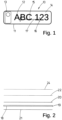
- FIG.1 An example of a license plate 10 according to the invention for a vehicle is shown in Fig.1 Such license plates 10 are also referred to as vehicle license plates or number plates. As a rule, these license plates 10 are attached to the front and/or rear of a vehicle. However, it is also conceivable that these license plates 10 are attached to other positions, such as on a windshield or a driver's cab of the vehicle. License plates 10 of the type described here serve to identify the vehicle and in some cases also the vehicle owner. For this purpose, letters and/or numbers are arranged on the license plate 10 or on a license plate body 11 forming the license plate 10. This label 12 can reproduce various information in coded form. The arrangement or the information content of this label 12 can differ from country to country.
- the embodiment of the license plate 10 shown has a country code 13.
- This country code 13 can be used to provide the vehicle with a country code that provides information about the country in which the vehicle is registered.
- a country code 13 is not arranged on the license plate 10 in all countries and should therefore not be limiting for the invention described here.
- the license plate 10 or the license plate body 11 is usually designed as an elongated rectangle. However, it is also conceivable that this rectangle is compressed or forms a square.
- the label 12 is arranged on a label field 14, centered on the surface of this rectangle or on the license plate body 11.
- License plates 10 are also known which, in addition to the label 12, have a data carrier 15 on which further data or information about the vehicle and/or the vehicle owner is stored in electronic form.
- An antenna 16 is assigned to this data carrier 15 for contactless reading or contactless writing to the data carrier 15.
- this antenna 16 is designed as a slot antenna. This slot antenna is formed by a recess in a metallic license plate or a metallic layer.
- the Antenna 16 or slot antenna is inductively or capacitively coupled to the data carrier 15.
- the slot antenna is arranged on the license plate body 11 in such a way that it does not overlap with the label 12.
- the antenna 16 can be located at any location on the label field 14. It is therefore also conceivable that the label 12 covers the antenna 16.
- the slot structure 17 of the antenna 16 shown forms an elongated "H".
- this slot structure 17 consists of several individual parallel slots, of a single slot or several connected slots that are arranged parallel and/or orthogonally.
- the license plate 10 described here essentially consists of the license plate body 11, which is designed as a cuboid and has a cavity 18 in its interior.
- FIG.2 An exploded view is shown for a representation of the license plate 10, in which the individual layers from which the license plate 10 is constructed are visible.
- the license plate body 11 is composed of a border 19, a cover part 20 and a base part 21. While the cover part 20 and the base part 21 are plate-like, the border 19 represents a type of circumferential collar. The height of the border 19 or the collar represents the thickness or strength of the license plate body 11.
- the base area of the cover part 20, the base part 21 and the border 19 are identical to the base area of the license plate body 11 or the license plate 10.
- the cover part 20 is placed on the border 19 and the base part 21 is also brought into contact with the border 19 parallel to the cover part 20. These three parts are then firmly connected to one another, preferably glued. As a result, the cover part 20, the base part 21 and the border 19 form a cuboid with the cavity 18 that forms the license plate body 11. It is conceivable that the license plate body 11 or the aforementioned individual parts are made of plastic. It is also conceivable that the individual parts of the license plate body 11 are metallic. Another embodiment can be it can also be provided that the license plate body 11 is made up of a single, connected part.
- the license plate body 11 or the cover part 20, the base part 21 and the border 19 are made of a plastic, it can be provided according to the invention that these parts are provided with a metallic coating on the outside or on the inside.
- This metallic coating is designed in such a way that it forms an electrical surface conductor. Due to this electrical conductivity of the surface, the license plate body 11 has a reflective effect, in particular for electromagnetic radiation, at least in some spectral ranges.
- a possibly metallized reflective foil 22 or a retroreflective foil is attached to the cover part 20 of the license plate body 11.
- This reflective foil 22 is preferably glued to the cover part 20.
- the Fig.4 The reflective foil 22 shown is identical in terms of its dimensions or at least almost identical to the dimensions or the base area of the license plate 10.
- the slot structure 17 forming the antenna 16 is positioned centered on the reflective foil 22. This slot structure 17 represents a recess or a cutout in the reflective foil 22. In this area, the reflective foil 22 is not metallized.
- the cover part 20 is also demetallized in the area in which the slot structure 17 is located on the reflective foil 22.
- the metallic coating 23 on the cover part 20 has an identical slot structure 17 which, when the reflective film 22 is joined to the cover part 20, is congruent with the slot structure 17 of the reflective film 22 or that the cover part 20 is completely demetallized, i.e. has no metallic coating 23.
- a particularly self-adhesive film 24 can then be applied to the reflective film 22.
- This film 24 is provided with the label 12. It is also conceivable that the film 24 is subsequently provided with the label 12. In addition, this film 24 can have the aforementioned country code 13.
- the dimensions of the film 24 are identical to the license plate body 11 or the license plate 10. While the film 24 is at least largely transparent to visible light, the label 12 is opaque. This means that the label 12 Reflective foil 22 covers the entire surface of the label 12 and thus only incoming light that does not fall on the label 12 is reflected by the reflective foil 22. Additional features can also be printed on the foil 24, such as a border 25.
- the foil 24 can also be used to Fig.1
- the data carrier shown which is at least in electrical or electromagnetic contact with the slot structure 17, is protected from manipulation or other environmental influences.
- the data carrier 15 arranged on the reflective film 22 can be covered by the film 24.
- the data carrier 15 is arranged on an inner side of the cover part 20 or on an upper side of the cover part 20.
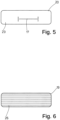
- spacer elements or structural elements 26 can be arranged in the cavity 18 of the license plate body 11 ( Fig.6 These structural elements 26 are in the Fig.6 In the exemplary embodiment shown, the structural elements 26 are designed like webs and are arranged parallel to one another within the border 19. The individual structural elements 26 can be in direct contact with the cover part 20 and the base part 21 of the license plate body 11. These structural elements 26 give the entire license plate body 11 a certain rigidity which protects it against mechanical forces such as twisting or bending. In particular, in the case of a license plate body 11 made of plastic, the structural elements 26 make a significant contribution to the stability of the license plate 10. It can also be provided that the structural elements 26 are also made of a plastic or a transparent plastic. The structural elements 26 can be arranged in the cavity 18 in such a way that they coincide with the slot structure 17 or that the slot structure 17 is not arranged above one or more of the structural elements 26.
- the base part 21 has a retroreflective coating 27 on a side facing the slot structure 17.
- This retroreflective coating 27 is at least dimensioned such that its length and width correspond to the dimensions of the slot structure 17 or are larger than the slot structure 17.
- This coating 27 can also be a This may be a film or retroreflective paint which is applied to the surface of the base part 21 during assembly of the license plate body 11.
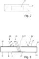
- Fig.8 is a highly schematic section through the license plate 10 or through the license plate body 11 with the cavity 18 and the metallic coating 23 of the license plate body 11, the reflective foil 22 and the foil 24.
- the metallic coating 23 and the reflective foil 22 are interrupted.
- the reflective foil 22 is not interrupted.
- the cover part 20 of the license plate body 11 is not metallically coated, only the foil 24, which is then metallized, has a recess for the slot structure 17.
- the retroreflective coating 27 is applied to the base part 21 of the license plate body 10 opposite the slot structure 17.
- the light rays pass through the slot structure 17 into the cavity 18, they are also reflected or retroreflected by the retroreflective coating 27 according to the arrows 29. If, for example, a picture is taken of the license plate 10 using a flash, the slot structure 17 is difficult or not visible at all, since the light that passes through the slot structure 17 is also reflected.
- the slot structure 17 can be positioned as desired relative to the lettering 12 without the legibility or visibility of the lettering 12 being impaired. Because the retroreflective coating 27 is larger in its dimensions than the slot structure 17, light rays that pass through the slot structure 17 at an acute angle to the upper side of the license plate 10 are also reflected back.
- a further advantage of the cuboid-like or hollow license plate body 11 is that the electromagnetic waves emitted by the antenna 16 Waves are reflected by the metalized base part 21 in the direction of travel or against the direction of travel, away from the vehicle.
- the electromagnetic waves emitted by the slot structure 17 or antenna 16 radiate away from the vehicle.
- the electromagnetic waves that are initially emitted in the direction of the vehicle are reflected back by the metallic coating 23 of the base part 21 and exit through the slot structure 17, thereby increasing the transmission power of the antenna 16.
- this design of the license plate body 11 also increases the reception power of the antenna 16. This increase in the transmission power means that the data carriers can be read without any problems even over a greater distance or a larger solid angle range. This proves to be particularly advantageous for use in road traffic.
- a plurality of holes 30 can be assigned to a rear side of the base part 21. These holes 30 can be arranged in the base part 21 according to a predetermined grid or arbitrarily ( Fig.9 ).
- the license plate 10 can be attached to the vehicle via these holes 30 using mounting aids 31.
- These mounting aids 31 can be rectangular or circular and have one or more, or as shown in the Fig.10 shown four, anchoring means 32.
- the mounting aids 31 can be attached to a body or a bumper of the vehicle via a centered opening 33. For example, a screw (not shown) can be tightened through the opening 33 so that the mounting aid 31 is firmly connected to the vehicle.
- the mounting aid 31 is attached to the vehicle in such a way that the anchoring means 32 can be connected to one of the holes 30.
- the individual anchoring means 32 are inserted through the holes 30, a barb-like connection is created between the mounting aid 31 and the base part 21 of the license plate body 11.
- the license plate 10 can thus be attached to almost any location on the vehicle in a simple and flexible manner in such a way that it is at least largely protected against attempts at manipulation.
- the license plate 10 is attached to the vehicle in a different manner.
Landscapes
- Engineering & Computer Science (AREA)
- Physics & Mathematics (AREA)
- Theoretical Computer Science (AREA)
- General Physics & Mathematics (AREA)
- Microelectronics & Electronic Packaging (AREA)
- Computer Hardware Design (AREA)
- Remote Sensing (AREA)
- Mechanical Engineering (AREA)
- Computer Networks & Wireless Communication (AREA)
- Computer Security & Cryptography (AREA)
- Radar, Positioning & Navigation (AREA)
- Vehicle Waterproofing, Decoration, And Sanitation Devices (AREA)
- Lock And Its Accessories (AREA)
Claims (12)
- Plaque minéralogique (10) destinée à un véhicule, comprenant un corps de plaque minéralogique (11) qui présente au moins un champ de lettrage (14) et au moins un lettrage (12) qui est associé au champ de lettrage (14) du corps de plaque minéralogique (11), dans laquelle un support de données (15) pouvant être lu sans contact et une antenne (16) sont associés au corps de plaque minéralogique (11), caractérisé en ce qu'au moins un espace creux (18) est disposé dans le corps de plaque minéralogique (11), dans laquelle une face avant (20) du corps de plaque minéralogique (11) recouvrant l'espace creux (18) ou un revêtement (23) de la face avant (20) présente une structure de fente (17) formant l'antenne (16) et dans laquelle l'au moins un espace creux (18) est formé par un espacement de la face avant (20) et d'une face arrière (21) du corps de plaque minéralogique (11), dans laquelle la face avant (20) et la face arrière (21) présentent une bordure commune (25) et la face avant (20) et une face intérieure de la face arrière (21), opposée à la structure de fente (17), est rétroréfléchissante dans l'espace creux (18).
- Plaque minéralogique (10) selon la revendication 1, caractérisée en ce que la face avant (20), la face arrière (21) et/ou la bordure (25) sont réalisées en un matériau transparent, de préférence une matière plastique, dans laquelle la face avant (20), la face arrière (21) et/ou la bordure (25) sont revêtues de l'extérieur et/ou de l'intérieur, au moins par zones, d'un revêtement métallique (23) présentant la structure de fente (17), ou en ce que la face avant (20), la face arrière (21) et/ou la bordure (25) sont réalisées en un matériau métallique.
- Plaque minéralogique (10) selon l'une des revendications précédentes, caractérisée en ce que la structure de fente (17) est réalisée sous la forme d'une fente droite qui est orientée parallèlement à un bord latéral de la face avant (20) du corps de plaque minéralogique (11) ou en ce que la structure de fente (17) est réalisée à partir de plusieurs fentes, en particulier orthogonales ou parallèles les unes aux autres, en particulier contiguës.
- Plaque minéralogique (10) selon l'une des revendications précédentes, caractérisée en ce que, dans l'espace creux (18) entre la face avant (20) et la face arrière (21), est disposé au moins un élément d'écartement ou un élément de structure (26), en particulier une pluralité d'éléments d'écartement ou d'éléments de structure (26), de préférence orientés parallèlement les uns aux autres.
- Plaque minéralogique (10) selon l'une des revendications précédentes, caractérisée en ce que la face avant (20) et une face intérieure de la face arrière (21), opposée à la structure de fente (17) dans l'espace creux (18) sont revêtues d'une couche rétroréfléchissante (27), dans laquelle la couche rétroréfléchissante de la face intérieure est plus grande que la structure de fente (17) .
- Plaque minéralogique (10) selon l'une des revendications précédentes, caractérisée en ce qu'une couche ou une feuille rétroréfléchissante, en particulier autocollante (24), qui présente une démétallisation correspondant à la forme de la structure de fente (17) ou un évidement en forme de fente correspondant, est appliquée sur la face avant (20) du corps de plaque minéralogique (11).
- Plaque minéralogique (10) selon l'une des revendications précédentes, caractérisée en ce que le lettrage (12), de préférence une couche ou un film (24), en particulier autocollant, présentant le lettrage (12), est appliqué sur la face avant (20) du corps de plaque minéralogique (11), en particulier sur une couche rétroréfléchissante du corps de plaque minéralogique (11) .
- Plaque minéralogique (10) selon l'une des revendications précédentes, caractérisée en ce que le support de données (15) est un support de données (15) générant un champ magnétique et est couplé, en particulier de manière inductive et/ou capacitive, à l'antenne (16), dans laquelle le support de données (15) est disposé sur ou dans le corps de plaque minéralogique (11) de manière isolée électriquement de l'antenne (16).
- Plaque minéralogique (10) selon l'une des revendications précédentes, caractérisée en ce que la structure de fente (17) est une ouverture, dans laquelle le percement agrandit de préférence la fente dans la zone d'une extrémité fermée, et le support de données (15) est disposé dans l'ouverture.
- Plaque minéralogique (10) selon l'une des revendications précédentes, caractérisée en ce que le support de données (15) est fixé dans la structure de fente (17) ou dans l'ouverture, en particulier recouvert d'un revêtement ou intégré dans celui-ci.
- Plaque minéralogique (10) selon l'une des revendications précédentes, caractérisée en ce que des aides au montage (31), en particulier des perforations ou d'autres logements, sont associées à la face arrière (21) du corps de plaque minéralogique (11), au moyen desquelles le corps de plaque minéralogique (11) peut être fixé au véhicule.
- Plaque minéralogique (10) selon l'une des revendications précédentes, caractérisée en ce que la structure de fente (17) est positionnée sur la face avant (20), dans un premier ou un deuxième tiers, mesuré à partir d'un côté longitudinal du corps de plaque minéralogique (11).
Applications Claiming Priority (2)
| Application Number | Priority Date | Filing Date | Title |
|---|---|---|---|
| DE102018007679.3A DE102018007679A1 (de) | 2018-09-28 | 2018-09-28 | Kennzeichen für ein Fahrzeug |
| PCT/EP2019/075066 WO2020064473A1 (fr) | 2018-09-28 | 2019-09-18 | Plaques minéralogiques pour véhicules |
Publications (3)
| Publication Number | Publication Date |
|---|---|
| EP3856574A1 EP3856574A1 (fr) | 2021-08-04 |
| EP3856574C0 EP3856574C0 (fr) | 2024-05-29 |
| EP3856574B1 true EP3856574B1 (fr) | 2024-05-29 |
Family
ID=66179190
Family Applications (1)
| Application Number | Title | Priority Date | Filing Date |
|---|---|---|---|
| EP19773042.7A Active EP3856574B1 (fr) | 2018-09-28 | 2019-09-18 | Plaques minéralogiques pour véhicules |
Country Status (7)
| Country | Link |
|---|---|
| US (1) | US11772580B2 (fr) |
| EP (1) | EP3856574B1 (fr) |
| AU (1) | AU2019202438B2 (fr) |
| DE (2) | DE102018007679A1 (fr) |
| ES (1) | ES2992458T3 (fr) |
| PL (1) | PL3856574T3 (fr) |
| WO (1) | WO2020064473A1 (fr) |
Families Citing this family (5)
| Publication number | Priority date | Publication date | Assignee | Title |
|---|---|---|---|---|
| DE102018002585A1 (de) * | 2018-03-28 | 2019-10-02 | Tönnjes Isi Patent Holding Gmbh | Fahrzeugidentifikationsmittel |
| DE102018005440A1 (de) * | 2018-07-11 | 2020-01-16 | Tönnjes Isi Patent Holding Gmbh | Kennzeichen für ein Fahrzeug und Verfahren zur Herstellung eines Kennzeichens für ein Fahrzeug |
| DE102019002722A1 (de) * | 2019-04-15 | 2020-10-15 | Tönnjes Isi Patent Holding Gmbh | Kennzeichen für ein Fahrzeug und Verfahren zur Herstellung eines Kennzeichens für ein Fahrzeug |
| DE102019121368A1 (de) * | 2019-08-07 | 2021-02-11 | Schreiner Group Gmbh & Co. Kg | Kennzeichnungsetikett, Kennzeichnungssystem und Verfahren zum Herstellen eines Kennzeichnungsetiketts |
| CN112396713B (zh) * | 2020-12-16 | 2021-07-27 | 台州隆达科技有限公司 | 一种能自动复位智能卡的etc卡机 |
Citations (2)
| Publication number | Priority date | Publication date | Assignee | Title |
|---|---|---|---|---|
| CN206551974U (zh) * | 2017-02-09 | 2017-10-13 | 苏州晟达力芯电子科技有限公司 | 一种无源射频车牌 |
| DE102019002722A1 (de) * | 2019-04-15 | 2020-10-15 | Tönnjes Isi Patent Holding Gmbh | Kennzeichen für ein Fahrzeug und Verfahren zur Herstellung eines Kennzeichens für ein Fahrzeug |
Family Cites Families (20)
| Publication number | Priority date | Publication date | Assignee | Title |
|---|---|---|---|---|
| AT319066B (de) * | 1971-08-04 | 1974-12-10 | Swarovski & Co | Verfahren zur Herstellung einer Kennzeichentafel |
| US5621571A (en) * | 1994-02-14 | 1997-04-15 | Minnesota Mining And Manufacturing Company | Integrated retroreflective electronic display |
| US5608391A (en) * | 1995-05-11 | 1997-03-04 | Minnesota Mining And Manufacturing Company | Electronic license plate architecture |
| DE19927683C1 (de) * | 1999-06-17 | 2001-01-25 | Sekurit Saint Gobain Deutsch | Sonnen- und Wärmestrahlen reflektierende Verbundglasscheibe |
| AUPQ939100A0 (en) * | 2000-08-15 | 2000-09-07 | Hudson, Anthony Gerard | Vehicle security apparatus |
| US20070171077A1 (en) * | 2006-01-26 | 2007-07-26 | Behrouz Kawarizadeh | License Plate Incorporating RFID Device |
| NZ549173A (en) * | 2006-08-15 | 2007-06-29 | Times 7 Holdings Ltd | Licence plate with integrated antenna |
| MX2009006781A (es) * | 2006-12-21 | 2010-01-15 | Neology Inc | Sistemas y métodos para una placa de metal habilitada con identificación por radio frecuencia. |
| WO2008131243A1 (fr) * | 2007-04-18 | 2008-10-30 | 3M Innovative Properties Company | Fonctionnalité d'identification radiofréquence couplée à un article de signalisation électroconducteur |
| DE102009033559A1 (de) * | 2008-11-04 | 2010-05-06 | J.H. Tönnjes E.A.S.T. GmbH & Co. KG | Kennzeichen für ein Fahrzeug |
| US7922094B2 (en) * | 2009-01-09 | 2011-04-12 | 3M Innovative Properties Company | RFID packaging and attachment methods and devices |
| JPWO2013115216A1 (ja) * | 2012-02-02 | 2015-05-11 | 日本カーバイド工業株式会社 | 標示板 |
| DE102012106594A1 (de) * | 2012-07-20 | 2014-01-23 | J.H. Tönnjes E.A.S.T. GmbH & Co. KG | Fahrzeugidentifikationsmittel |
| CN103661151B (zh) * | 2012-08-30 | 2017-03-01 | 祝辰 | 电子车牌 |
| PT107661A (pt) * | 2014-05-27 | 2015-11-27 | Porta Saber Comércio E Serviços De Consultoria Unipessoal Lda | Chapa de matrícula para veículos automóveis com dispositivo de identificação de rádio frequência (rfid) |
| DE102014012291A1 (de) | 2014-08-22 | 2016-02-25 | Tönnjes Isi Patent Holding Gmbh | Kennzeichen für ein Fahrzeug |
| EP3944150A1 (fr) * | 2015-04-07 | 2022-01-26 | Neology, Inc. | Étiquette d'identification de fréquence radio dans une plaque |
| US9694738B2 (en) * | 2015-08-14 | 2017-07-04 | Glen Goeloe | Shaped-array LED license plate display |
| DE102018002585A1 (de) * | 2018-03-28 | 2019-10-02 | Tönnjes Isi Patent Holding Gmbh | Fahrzeugidentifikationsmittel |
| DE102018007540A1 (de) * | 2018-06-15 | 2019-12-19 | J.H. Tönnjes Gmbh | Verfahren und Vorrichtung zum Ausstatten eines Kennzeichens, vorzugsweise eines Kraftfahrzeug-Kennzeichens, mit einem Datenträger und ein Kennzeichen |
-
2018
- 2018-09-28 DE DE102018007679.3A patent/DE102018007679A1/de not_active Withdrawn
-
2019
- 2019-03-13 DE DE202019001169.2U patent/DE202019001169U1/de not_active Expired - Lifetime
- 2019-04-08 AU AU2019202438A patent/AU2019202438B2/en active Active
- 2019-09-18 WO PCT/EP2019/075066 patent/WO2020064473A1/fr not_active Ceased
- 2019-09-18 US US17/279,147 patent/US11772580B2/en active Active
- 2019-09-18 EP EP19773042.7A patent/EP3856574B1/fr active Active
- 2019-09-18 PL PL19773042.7T patent/PL3856574T3/pl unknown
- 2019-09-18 ES ES19773042T patent/ES2992458T3/es active Active
Patent Citations (2)
| Publication number | Priority date | Publication date | Assignee | Title |
|---|---|---|---|---|
| CN206551974U (zh) * | 2017-02-09 | 2017-10-13 | 苏州晟达力芯电子科技有限公司 | 一种无源射频车牌 |
| DE102019002722A1 (de) * | 2019-04-15 | 2020-10-15 | Tönnjes Isi Patent Holding Gmbh | Kennzeichen für ein Fahrzeug und Verfahren zur Herstellung eines Kennzeichens für ein Fahrzeug |
Also Published As
| Publication number | Publication date |
|---|---|
| ES2992458T3 (es) | 2024-12-12 |
| EP3856574A1 (fr) | 2021-08-04 |
| AU2019202438B2 (en) | 2020-12-24 |
| DE102018007679A1 (de) | 2020-04-02 |
| US20210387582A1 (en) | 2021-12-16 |
| AU2019202438A1 (en) | 2020-04-16 |
| PL3856574T3 (pl) | 2024-09-30 |
| DE202019001169U1 (de) | 2019-04-02 |
| WO2020064473A1 (fr) | 2020-04-02 |
| EP3856574C0 (fr) | 2024-05-29 |
| US11772580B2 (en) | 2023-10-03 |
Similar Documents
| Publication | Publication Date | Title |
|---|---|---|
| EP3856574B1 (fr) | Plaques minéralogiques pour véhicules | |
| EP2344364B1 (fr) | Plaques minéralogiques pour véhicules | |
| EP3776359B1 (fr) | Moyen d'identification de véhicule | |
| WO2016026543A1 (fr) | Plaque d'immatriculation pour véhicule | |
| EP1530731A1 (fr) | Dispositif de detection et d'evaluation d'objets situes dans la zone environnante d'un vehicule | |
| EP2466552A1 (fr) | Système d'information à bord doté d'une antenne mobile | |
| EP1886263B1 (fr) | Systeme comportant un transpondeur et un element metallique | |
| EP3956179B1 (fr) | Plaque d'immatriculation pour un véhicule et procédé de fabrication d'une plaque d'immatriculation pour un véhicule | |
| AT514156B1 (de) | Getränkedose | |
| DE10028801A1 (de) | Radom für einen Radarsensor | |
| WO2021032318A1 (fr) | Carte à puce | |
| DE102022000123B4 (de) | Multifunktionales RFID-Radaretiketten-System | |
| EP3820742B1 (fr) | Plaque d'immatriculation pour véhicule et procédé de production d'une plaque d'immatriculation pour véhicule | |
| EP1860733B1 (fr) | Elément d'absorption pour rayonnement électromagnétique à haute fréquence | |
| EP3769261B1 (fr) | Agencement d'une plaque et d'un support de plaque portant la plaque | |
| DE29811147U1 (de) | Antennen aus flächigen Elementen | |
| DE202022000086U1 (de) | Multifunktionales RFID-Radaretiketten-System | |
| DE102022115130A1 (de) | Informationsschild | |
| EP3132388B1 (fr) | Appareil pour la prévention d'un vol de données, fraude d'identité et de payement lors d'une transmission sans contact de données par ondes électromagnétiques | |
| HK40049647B (en) | License plate for a vehicle | |
| DE202008011278U1 (de) | Transponder mit Plattenantenne | |
| DE102017001798A1 (de) | Sicherungselement für Schilder | |
| DE102006051902A1 (de) | Transponderanordnung und Verfahren zum Betrieb von Transpondern | |
| DE29909696U1 (de) | Integrierte Antennenvorrichtung für ein Kraftfahrzeug mit Reflektor | |
| DE102016114671A1 (de) | Kleinteilbehälter mit RFID |
Legal Events
| Date | Code | Title | Description |
|---|---|---|---|
| STAA | Information on the status of an ep patent application or granted ep patent |
Free format text: STATUS: UNKNOWN |
|
| STAA | Information on the status of an ep patent application or granted ep patent |
Free format text: STATUS: THE INTERNATIONAL PUBLICATION HAS BEEN MADE |
|
| PUAI | Public reference made under article 153(3) epc to a published international application that has entered the european phase |
Free format text: ORIGINAL CODE: 0009012 |
|
| STAA | Information on the status of an ep patent application or granted ep patent |
Free format text: STATUS: REQUEST FOR EXAMINATION WAS MADE |
|
| 17P | Request for examination filed |
Effective date: 20210324 |
|
| AK | Designated contracting states |
Kind code of ref document: A1 Designated state(s): AL AT BE BG CH CY CZ DE DK EE ES FI FR GB GR HR HU IE IS IT LI LT LU LV MC MK MT NL NO PL PT RO RS SE SI SK SM TR |
|
| REG | Reference to a national code |
Ref country code: HK Ref legal event code: DE Ref document number: 40049647 Country of ref document: HK |
|
| DAV | Request for validation of the european patent (deleted) | ||
| DAX | Request for extension of the european patent (deleted) | ||
| STAA | Information on the status of an ep patent application or granted ep patent |
Free format text: STATUS: EXAMINATION IS IN PROGRESS |
|
| 17Q | First examination report despatched |
Effective date: 20220419 |
|
| GRAP | Despatch of communication of intention to grant a patent |
Free format text: ORIGINAL CODE: EPIDOSNIGR1 |
|
| STAA | Information on the status of an ep patent application or granted ep patent |
Free format text: STATUS: GRANT OF PATENT IS INTENDED |
|
| INTG | Intention to grant announced |
Effective date: 20240103 |
|
| GRAS | Grant fee paid |
Free format text: ORIGINAL CODE: EPIDOSNIGR3 |
|
| GRAA | (expected) grant |
Free format text: ORIGINAL CODE: 0009210 |
|
| STAA | Information on the status of an ep patent application or granted ep patent |
Free format text: STATUS: THE PATENT HAS BEEN GRANTED |
|
| AK | Designated contracting states |
Kind code of ref document: B1 Designated state(s): AL AT BE BG CH CY CZ DE DK EE ES FI FR GB GR HR HU IE IS IT LI LT LU LV MC MK MT NL NO PL PT RO RS SE SI SK SM TR |
|
| REG | Reference to a national code |
Ref country code: CH Ref legal event code: EP |
|
| REG | Reference to a national code |
Ref country code: IE Ref legal event code: FG4D Free format text: LANGUAGE OF EP DOCUMENT: GERMAN |
|
| REG | Reference to a national code |
Ref country code: DE Ref legal event code: R096 Ref document number: 502019011377 Country of ref document: DE |
|
| U01 | Request for unitary effect filed |
Effective date: 20240618 |
|
| U07 | Unitary effect registered |
Designated state(s): AT BE BG DE DK EE FI FR IT LT LU LV MT NL PT SE SI Effective date: 20240628 |
|
| PG25 | Lapsed in a contracting state [announced via postgrant information from national office to epo] |
Ref country code: IS Free format text: LAPSE BECAUSE OF FAILURE TO SUBMIT A TRANSLATION OF THE DESCRIPTION OR TO PAY THE FEE WITHIN THE PRESCRIBED TIME-LIMIT Effective date: 20240929 |
|
| U20 | Renewal fee for the european patent with unitary effect paid |
Year of fee payment: 6 Effective date: 20240830 |
|
| PG25 | Lapsed in a contracting state [announced via postgrant information from national office to epo] |
Ref country code: HR Free format text: LAPSE BECAUSE OF FAILURE TO SUBMIT A TRANSLATION OF THE DESCRIPTION OR TO PAY THE FEE WITHIN THE PRESCRIBED TIME-LIMIT Effective date: 20240529 |
|
| PG25 | Lapsed in a contracting state [announced via postgrant information from national office to epo] |
Ref country code: GR Free format text: LAPSE BECAUSE OF FAILURE TO SUBMIT A TRANSLATION OF THE DESCRIPTION OR TO PAY THE FEE WITHIN THE PRESCRIBED TIME-LIMIT Effective date: 20240830 |
|
| PG25 | Lapsed in a contracting state [announced via postgrant information from national office to epo] |
Ref country code: NO Free format text: LAPSE BECAUSE OF FAILURE TO SUBMIT A TRANSLATION OF THE DESCRIPTION OR TO PAY THE FEE WITHIN THE PRESCRIBED TIME-LIMIT Effective date: 20240829 Ref country code: IS Free format text: LAPSE BECAUSE OF FAILURE TO SUBMIT A TRANSLATION OF THE DESCRIPTION OR TO PAY THE FEE WITHIN THE PRESCRIBED TIME-LIMIT Effective date: 20240929 Ref country code: HR Free format text: LAPSE BECAUSE OF FAILURE TO SUBMIT A TRANSLATION OF THE DESCRIPTION OR TO PAY THE FEE WITHIN THE PRESCRIBED TIME-LIMIT Effective date: 20240529 Ref country code: GR Free format text: LAPSE BECAUSE OF FAILURE TO SUBMIT A TRANSLATION OF THE DESCRIPTION OR TO PAY THE FEE WITHIN THE PRESCRIBED TIME-LIMIT Effective date: 20240830 Ref country code: RS Free format text: LAPSE BECAUSE OF FAILURE TO SUBMIT A TRANSLATION OF THE DESCRIPTION OR TO PAY THE FEE WITHIN THE PRESCRIBED TIME-LIMIT Effective date: 20240829 |
|
| REG | Reference to a national code |
Ref country code: ES Ref legal event code: FG2A Ref document number: 2992458 Country of ref document: ES Kind code of ref document: T3 Effective date: 20241212 |
|
| PG25 | Lapsed in a contracting state [announced via postgrant information from national office to epo] |
Ref country code: CZ Free format text: LAPSE BECAUSE OF FAILURE TO SUBMIT A TRANSLATION OF THE DESCRIPTION OR TO PAY THE FEE WITHIN THE PRESCRIBED TIME-LIMIT Effective date: 20240529 |
|
| PG25 | Lapsed in a contracting state [announced via postgrant information from national office to epo] |
Ref country code: RO Free format text: LAPSE BECAUSE OF FAILURE TO SUBMIT A TRANSLATION OF THE DESCRIPTION OR TO PAY THE FEE WITHIN THE PRESCRIBED TIME-LIMIT Effective date: 20240529 Ref country code: SK Free format text: LAPSE BECAUSE OF FAILURE TO SUBMIT A TRANSLATION OF THE DESCRIPTION OR TO PAY THE FEE WITHIN THE PRESCRIBED TIME-LIMIT Effective date: 20240529 |
|
| PG25 | Lapsed in a contracting state [announced via postgrant information from national office to epo] |
Ref country code: SM Free format text: LAPSE BECAUSE OF FAILURE TO SUBMIT A TRANSLATION OF THE DESCRIPTION OR TO PAY THE FEE WITHIN THE PRESCRIBED TIME-LIMIT Effective date: 20240529 |
|
| PG25 | Lapsed in a contracting state [announced via postgrant information from national office to epo] |
Ref country code: SM Free format text: LAPSE BECAUSE OF FAILURE TO SUBMIT A TRANSLATION OF THE DESCRIPTION OR TO PAY THE FEE WITHIN THE PRESCRIBED TIME-LIMIT Effective date: 20240529 Ref country code: SK Free format text: LAPSE BECAUSE OF FAILURE TO SUBMIT A TRANSLATION OF THE DESCRIPTION OR TO PAY THE FEE WITHIN THE PRESCRIBED TIME-LIMIT Effective date: 20240529 Ref country code: RO Free format text: LAPSE BECAUSE OF FAILURE TO SUBMIT A TRANSLATION OF THE DESCRIPTION OR TO PAY THE FEE WITHIN THE PRESCRIBED TIME-LIMIT Effective date: 20240529 Ref country code: CZ Free format text: LAPSE BECAUSE OF FAILURE TO SUBMIT A TRANSLATION OF THE DESCRIPTION OR TO PAY THE FEE WITHIN THE PRESCRIBED TIME-LIMIT Effective date: 20240529 |
|
| PLBE | No opposition filed within time limit |
Free format text: ORIGINAL CODE: 0009261 |
|
| STAA | Information on the status of an ep patent application or granted ep patent |
Free format text: STATUS: NO OPPOSITION FILED WITHIN TIME LIMIT |
|
| PG25 | Lapsed in a contracting state [announced via postgrant information from national office to epo] |
Ref country code: MC Free format text: LAPSE BECAUSE OF FAILURE TO SUBMIT A TRANSLATION OF THE DESCRIPTION OR TO PAY THE FEE WITHIN THE PRESCRIBED TIME-LIMIT Effective date: 20240529 |
|
| REG | Reference to a national code |
Ref country code: CH Ref legal event code: PL |
|
| 26N | No opposition filed |
Effective date: 20250303 |
|
| PG25 | Lapsed in a contracting state [announced via postgrant information from national office to epo] |
Ref country code: CH Free format text: LAPSE BECAUSE OF NON-PAYMENT OF DUE FEES Effective date: 20240930 |
|
| U20 | Renewal fee for the european patent with unitary effect paid |
Year of fee payment: 7 Effective date: 20250828 |
|
| PGFP | Annual fee paid to national office [announced via postgrant information from national office to epo] |
Ref country code: PL Payment date: 20250905 Year of fee payment: 7 |
|
| PGFP | Annual fee paid to national office [announced via postgrant information from national office to epo] |
Ref country code: GB Payment date: 20250923 Year of fee payment: 7 |
|
| PGFP | Annual fee paid to national office [announced via postgrant information from national office to epo] |
Ref country code: IE Payment date: 20250919 Year of fee payment: 7 |
|
| PG25 | Lapsed in a contracting state [announced via postgrant information from national office to epo] |
Ref country code: CY Free format text: LAPSE BECAUSE OF FAILURE TO SUBMIT A TRANSLATION OF THE DESCRIPTION OR TO PAY THE FEE WITHIN THE PRESCRIBED TIME-LIMIT; INVALID AB INITIO Effective date: 20190918 |
|
| PGFP | Annual fee paid to national office [announced via postgrant information from national office to epo] |
Ref country code: ES Payment date: 20251020 Year of fee payment: 7 |
|
| PG25 | Lapsed in a contracting state [announced via postgrant information from national office to epo] |
Ref country code: HU Free format text: LAPSE BECAUSE OF FAILURE TO SUBMIT A TRANSLATION OF THE DESCRIPTION OR TO PAY THE FEE WITHIN THE PRESCRIBED TIME-LIMIT; INVALID AB INITIO Effective date: 20190918 |