EP3856625B1 - Transmission à manivelle comprenant un arbre de manivelle à relier à au moins une manivelle au pied ou manuelle - Google Patents
Transmission à manivelle comprenant un arbre de manivelle à relier à au moins une manivelle au pied ou manuelle Download PDFInfo
- Publication number
- EP3856625B1 EP3856625B1 EP19782934.4A EP19782934A EP3856625B1 EP 3856625 B1 EP3856625 B1 EP 3856625B1 EP 19782934 A EP19782934 A EP 19782934A EP 3856625 B1 EP3856625 B1 EP 3856625B1
- Authority
- EP
- European Patent Office
- Prior art keywords
- crank
- crankshaft
- transmission according
- torque
- air gap
- Prior art date
- Legal status (The legal status is an assumption and is not a legal conclusion. Google has not performed a legal analysis and makes no representation as to the accuracy of the status listed.)
- Active
Links
Images


Classifications
-
- B—PERFORMING OPERATIONS; TRANSPORTING
- B62—LAND VEHICLES FOR TRAVELLING OTHERWISE THAN ON RAILS
- B62M—RIDER PROPULSION OF WHEELED VEHICLES OR SLEDGES; POWERED PROPULSION OF SLEDGES OR SINGLE-TRACK CYCLES; TRANSMISSIONS SPECIALLY ADAPTED FOR SUCH VEHICLES
- B62M3/00—Construction of cranks operated by hand or foot
-
- F—MECHANICAL ENGINEERING; LIGHTING; HEATING; WEAPONS; BLASTING
- F16—ENGINEERING ELEMENTS AND UNITS; GENERAL MEASURES FOR PRODUCING AND MAINTAINING EFFECTIVE FUNCTIONING OF MACHINES OR INSTALLATIONS; THERMAL INSULATION IN GENERAL
- F16D—COUPLINGS FOR TRANSMITTING ROTATION; CLUTCHES; BRAKES
- F16D3/00—Yielding couplings, i.e. with means permitting movement between the connected parts during the drive
- F16D3/02—Yielding couplings, i.e. with means permitting movement between the connected parts during the drive adapted to specific functions
- F16D3/12—Yielding couplings, i.e. with means permitting movement between the connected parts during the drive adapted to specific functions specially adapted for accumulation of energy to absorb shocks or vibration
-
- G—PHYSICS
- G01—MEASURING; TESTING
- G01D—MEASURING NOT SPECIALLY ADAPTED FOR A SPECIFIC VARIABLE; ARRANGEMENTS FOR MEASURING TWO OR MORE VARIABLES NOT COVERED IN A SINGLE OTHER SUBCLASS; TARIFF METERING APPARATUS; MEASURING OR TESTING NOT OTHERWISE PROVIDED FOR
- G01D5/00—Mechanical means for transferring the output of a sensing member; Means for converting the output of a sensing member to another variable where the form or nature of the sensing member does not constrain the means for converting; Transducers not specially adapted for a specific variable
- G01D5/12—Mechanical means for transferring the output of a sensing member; Means for converting the output of a sensing member to another variable where the form or nature of the sensing member does not constrain the means for converting; Transducers not specially adapted for a specific variable using electric or magnetic means
- G01D5/14—Mechanical means for transferring the output of a sensing member; Means for converting the output of a sensing member to another variable where the form or nature of the sensing member does not constrain the means for converting; Transducers not specially adapted for a specific variable using electric or magnetic means influencing the magnitude of a current or voltage
- G01D5/142—Mechanical means for transferring the output of a sensing member; Means for converting the output of a sensing member to another variable where the form or nature of the sensing member does not constrain the means for converting; Transducers not specially adapted for a specific variable using electric or magnetic means influencing the magnitude of a current or voltage using Hall-effect devices
- G01D5/145—Mechanical means for transferring the output of a sensing member; Means for converting the output of a sensing member to another variable where the form or nature of the sensing member does not constrain the means for converting; Transducers not specially adapted for a specific variable using electric or magnetic means influencing the magnitude of a current or voltage using Hall-effect devices influenced by the relative movement between the Hall device and magnetic fields
-
- G—PHYSICS
- G01—MEASURING; TESTING
- G01L—MEASURING FORCE, STRESS, TORQUE, WORK, MECHANICAL POWER, MECHANICAL EFFICIENCY, OR FLUID PRESSURE
- G01L3/00—Measuring torque, work, mechanical power, or mechanical efficiency, in general
- G01L3/02—Rotary-transmission dynamometers
- G01L3/04—Rotary-transmission dynamometers wherein the torque-transmitting element comprises a torsionally-flexible shaft
- G01L3/10—Rotary-transmission dynamometers wherein the torque-transmitting element comprises a torsionally-flexible shaft involving electric or magnetic means for indicating
- G01L3/101—Rotary-transmission dynamometers wherein the torque-transmitting element comprises a torsionally-flexible shaft involving electric or magnetic means for indicating involving magnetic or electromagnetic means
- G01L3/104—Rotary-transmission dynamometers wherein the torque-transmitting element comprises a torsionally-flexible shaft involving electric or magnetic means for indicating involving magnetic or electromagnetic means involving permanent magnets
-
- B—PERFORMING OPERATIONS; TRANSPORTING
- B62—LAND VEHICLES FOR TRAVELLING OTHERWISE THAN ON RAILS
- B62J—CYCLE SADDLES OR SEATS; AUXILIARY DEVICES OR ACCESSORIES SPECIALLY ADAPTED TO CYCLES AND NOT OTHERWISE PROVIDED FOR, e.g. ARTICLE CARRIERS OR CYCLE PROTECTORS
- B62J45/00—Electrical equipment arrangements specially adapted for use as accessories on cycles, not otherwise provided for
- B62J45/40—Sensor arrangements; Mounting thereof
- B62J45/41—Sensor arrangements; Mounting thereof characterised by the type of sensor
- B62J45/413—Rotation sensors
-
- B—PERFORMING OPERATIONS; TRANSPORTING
- B62—LAND VEHICLES FOR TRAVELLING OTHERWISE THAN ON RAILS
- B62J—CYCLE SADDLES OR SEATS; AUXILIARY DEVICES OR ACCESSORIES SPECIALLY ADAPTED TO CYCLES AND NOT OTHERWISE PROVIDED FOR, e.g. ARTICLE CARRIERS OR CYCLE PROTECTORS
- B62J45/00—Electrical equipment arrangements specially adapted for use as accessories on cycles, not otherwise provided for
- B62J45/40—Sensor arrangements; Mounting thereof
- B62J45/42—Sensor arrangements; Mounting thereof characterised by mounting
- B62J45/421—Sensor arrangements; Mounting thereof characterised by mounting at the pedal crank
-
- B—PERFORMING OPERATIONS; TRANSPORTING
- B62—LAND VEHICLES FOR TRAVELLING OTHERWISE THAN ON RAILS
- B62M—RIDER PROPULSION OF WHEELED VEHICLES OR SLEDGES; POWERED PROPULSION OF SLEDGES OR SINGLE-TRACK CYCLES; TRANSMISSIONS SPECIALLY ADAPTED FOR SUCH VEHICLES
- B62M21/00—Transmissions characterised by use of resilient elements therein
-
- B—PERFORMING OPERATIONS; TRANSPORTING
- B62—LAND VEHICLES FOR TRAVELLING OTHERWISE THAN ON RAILS
- B62M—RIDER PROPULSION OF WHEELED VEHICLES OR SLEDGES; POWERED PROPULSION OF SLEDGES OR SINGLE-TRACK CYCLES; TRANSMISSIONS SPECIALLY ADAPTED FOR SUCH VEHICLES
- B62M3/00—Construction of cranks operated by hand or foot
- B62M3/16—Accessories
-
- F—MECHANICAL ENGINEERING; LIGHTING; HEATING; WEAPONS; BLASTING
- F16—ENGINEERING ELEMENTS AND UNITS; GENERAL MEASURES FOR PRODUCING AND MAINTAINING EFFECTIVE FUNCTIONING OF MACHINES OR INSTALLATIONS; THERMAL INSULATION IN GENERAL
- F16D—COUPLINGS FOR TRANSMITTING ROTATION; CLUTCHES; BRAKES
- F16D2300/00—Special features for couplings or clutches
- F16D2300/18—Sensors; Details or arrangements thereof
-
- F—MECHANICAL ENGINEERING; LIGHTING; HEATING; WEAPONS; BLASTING
- F16—ENGINEERING ELEMENTS AND UNITS; GENERAL MEASURES FOR PRODUCING AND MAINTAINING EFFECTIVE FUNCTIONING OF MACHINES OR INSTALLATIONS; THERMAL INSULATION IN GENERAL
- F16D—COUPLINGS FOR TRANSMITTING ROTATION; CLUTCHES; BRAKES
- F16D2300/00—Special features for couplings or clutches
- F16D2300/22—Vibration damping
-
- Y—GENERAL TAGGING OF NEW TECHNOLOGICAL DEVELOPMENTS; GENERAL TAGGING OF CROSS-SECTIONAL TECHNOLOGIES SPANNING OVER SEVERAL SECTIONS OF THE IPC; TECHNICAL SUBJECTS COVERED BY FORMER USPC CROSS-REFERENCE ART COLLECTIONS [XRACs] AND DIGESTS
- Y10—TECHNICAL SUBJECTS COVERED BY FORMER USPC
- Y10T—TECHNICAL SUBJECTS COVERED BY FORMER US CLASSIFICATION
- Y10T74/00—Machine element or mechanism
- Y10T74/21—Elements
- Y10T74/2164—Cranks and pedals
- Y10T74/2165—Cranks and pedals with attached gear
Definitions
- the invention relates to a crank mechanism with a crankshaft for connection to at least one foot or hand crank according to the preamble of claim 1.
- a crank gear according to the invention is understood to mean any gear for vehicles in which a drive is provided by a crank rotated by a person using physical force and this torque is transmitted from there via a mechanical gear to at least one propulsion element such as a wheel or a paddle wheel, i.e. in addition to conventional bicycle gears, also gears for multi-wheeled vehicles and/or additionally motor-driven vehicles such as so-called e-bikes or pedelecs as well as other such vehicles such as pedal boats or the like.
- This sensor arrangement includes the formation of a torsion element on a shaft by means of a cross-sectional tapered shape, whereby the twisting of the shaft under load or the resulting The angle of rotation is recorded using a magnetic sensor and the applied torque is determined via this angle of rotation.
- an inner bearing unit is known primarily for installation in bicycles with a measuring sensor system for torque, angle of rotation and speed or a combination of the aforementioned measured variables, wherein a torsionally rigid inner bearing shaft is connected on one side to an elastic element pushed over it, such as a spring, sleeve, a combination thereof or the like, for the flow of force through a freewheel or other type of coupling and transmits the rotary movement to this torsionally elastic element, which is provided with a device for power output on the side opposite the connection to the inner bearing shaft.
- an elastic element such as a spring, sleeve, a combination thereof or the like
- the document DE 10 2014 207 761 A1 relates to a device for detecting a torque acting on a bottom bracket shaft of a bicycle, comprising: a measuring sensor configured to detect a torque-dependent differential angle between a first shaft portion of the bottom bracket shaft and a second shaft portion of the bottom bracket shaft axially spaced from the first shaft portion; and an output device for outputting a torque-dependent signal based on the differential angle.
- the invention has the object of proposing a crank mechanism in which the torque introduced into a crank mechanism via a crankshaft can be detected by sensors.
- crank mechanism having the features of claim 1.
- a transmission according to the invention has a coupling unit between the crankshaft and at least one gear wheel driven by the crankshaft, which, under load, has a torque-dependent angular offset between a crank-side receiving area, which receives the torque generated by the crank, and an output area, which outputs the torque to the gear wheel.
- Detecting the direction of rotation of the absorbed torque can be advantageous, for example, when using a so-called coaster brake.
- the recording of the magnitude of the absorbed torque can, if necessary, be used in conjunction with transmission data to record data such as the generated power, the crank force, etc.
- data can be used for storage and display the data can be further used for a driver or for control purposes, e.g. for automatic gear shifting or for controlling an auxiliary drive.
- a converter unit for converting the angular displacement into a change in magnetic flux and a magnetic field-sensitive sensor for detecting this change.
- a torsion element provides a simple method for generating a torque-dependent angular misalignment.
- the torsion element is elastic at least in certain areas, meaning it can be deformed against a restoring moment.
- the restoring moment depends on the degree of deformation and thus on the load or the absorbed torque, so that the magnitude of the angular misalignment thus generated also depends on the magnitude of the absorbed torque. Due to the restoring moment, the torsion element also returns to its original shape when the load decreases.
- the torsion element is arranged in a cavity of the crankshaft.
- the torsion element can have a certain length if this is required, yet is housed in a space-saving manner.
- the coupling point for coupling to the driven gear wheel can easily be positioned in the cavity exactly where the corresponding gear wheel is located.
- the connection of the torsion element to the crankshaft can be made in the immediate vicinity of the crank, ensuring that the torque introduced by the crank is actually fully transmitted to the torsion element and that the resulting angular offset is reflected.
- the torsion element is advantageously a torsion bar with the corresponding length extension between the connection points.
- the gear wheel is typically designed as a toothed wheel and can be driven by a connecting element between the torsion element and the gear wheel.
- a connecting element is particularly advantageous when arranged in a continuous, at least partially hollow crankshaft, as it can penetrate the wall of the hollow shaft and thus bridge the gap between the torsion element and the gear wheel.
- a mechanical end stop is provided. This can be formed, for example, by the edge of a slotted hole through which the connecting element passes.
- the converter unit is preferably designed to convert the angular offset into a change in magnetic flux.
- at least one magnet and at least two mutually rotatable guide elements are provided.
- the guide elements are shaped and arranged such that they change the shape of an air gap located within the magnetic field of the magnet depending on their relative angular position to one another. This angle-dependent change in the air gap causes an angle-dependent change in the overall magnetic return flux.
- one guide element is provided with a toothed inner circumference and the other guide element with a toothed outer circumference, so that the shape of the air gap depends on the angular position of these teeth.
- the two guide elements can be dimensioned such that the toothed outer circumference can rotate within the toothed inner circumference, allowing both guide elements to be arranged axially at the same height inside one another.
- a Hall sensor for example, is used as a magnetic field-sensitive sensor, with which the aforementioned changes in the magnetic flux can be easily detected.
- the magnetic field sensitive sensor is preferably spaced apart from the two guide elements on a structurally placed in a suitable location where there is still sufficient magnetic flux for the measurement.
- a ring magnet is arranged concentrically to the crankshaft as the magnet, so that an outer return circuit of the magnetic field is formed outside the outer circumference of the ring magnet and an inner return circuit of the magnetic field is formed within the inner circumference of the ring magnet.
- the angle-dependent variable air gap area is located in the area of the outer return circuit and the magnetic field sensitive sensor in the area of the inner return circuit or vice versa.
- the senor can be positioned at a distance from the conducting elements. This significantly simplifies the design.
- the magnetic flux can be varied by changing the overrotation of the tooth-shaped guide elements in both return circuits.
- the second, inner return circuit can be designed to generate a homogeneous magnetic field in the circumferential direction of the axle. This allows a magnetic field-sensitive sensor to be fixed in position relative to a non-rotating component, for example, fixed in position relative to a gearbox housing. The sensor signal is thus constant as the shaft rotates. and can be changed by varying the over-rotation of the conducting elements of the outer return circuits.
- the sensor signal can be used by an evaluation unit to determine the torque introduced.
- the invention enables, particularly in conjunction with the described developments, a robust, space-saving and cost-effective sensor system.
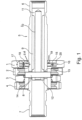
- Fig. 1 shows the essential components of a transmission according to the invention. Specifically, these are various gearwheels (1, 2, 3, 4), of which the first gearwheel (1) is driven via a crankshaft (5).
- Crankshaft 5 is provided with gears (6, 7) on both sides for mounting foot or hand cranks.
- a connecting pin (8) protrudes from the crankshaft and serves to connect the driven gear wheel (1), as explained further below.
- FIG. 1 The inner cavity (9) of the crankshaft (5) can also be seen, in which a torsion bar (10) is arranged.
- the torsion bar is connected to the crankshaft in a rotationally fixed manner at its crank-side receiving area (11), for example by being pressed, welded, or shrunk on.
- the torsion bar (10) is connected to the gear wheel (1) in a rotationally fixed manner by means of the connecting pin (8) as a drive element for the gear wheel.
- the passage (13) through the wall of the crankshaft (5) is designed as an elongated hole (see Fig. 4 ), the edge (14) of which forms a mechanical end stop for the rotation of the connecting pin in the passage (13).
- a ring magnet (15) is inserted into a recess (16) of the gear wheel (1), with the two magnetic poles N,S in axial direction. This results in an outer return circuit (17) and an inner return circuit (18), as indicated by arrows.
- a Hall sensor (19) is located in the area of the inner return circuit.
- An annular space (20) is provided for the arrangement of the Fig. 1 Guide elements (not shown) are arranged outside the Hall sensor (19) and extend far into the area of the outer return circuit (18).
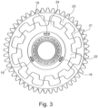
- the guide elements (21, 22) to be accommodated in the annular space (20) are shown.
- the outer guide element (21) and the inner guide element (22) are provided with an internal toothing (23) and an external toothing (24), respectively, which extend into an air gap (25) of the outer return circuit.
- the teeth (23, 24) form the contours of the air gap (25), whereby the shape of the outer air gap (25) can be changed by rotating the guide elements (21, 22).
- Fig. 2 and 3 show two different angular positions of the guide elements (21, 22) relative to each other.
- the teeth (23, 24) and the air gap (25) are located in the area of the outer return circuit (17).
- the Hall sensor (19) the Hall sensor (19)
- the sensor signal remains constant as the shaft rotates.
- the overrotation of the conducting elements of the outer return circuit By changing the overrotation of the conducting elements of the outer return circuit, the magnetic field in the inner air gap (26) can be varied. If more magnetic flux flows due to greater overrotation of the conducting elements of the outer return circuit, less magnetic flux flows through the inner return circuit and thus also through the inner air gap (26). If the overrotation of the conducting elements of the outer return circuit is reduced, the opposite applies.
- the inner guide element (22) is connected to the crankshaft, and the outer guide element (21) is connected to the gear wheel (1) in a rotationally fixed manner.
- the angular offset generated by the torsion element (10) is established between the two guide elements (21, 22).
- the two guide elements (21, 22), the ring magnet (15), and at least one Hall sensor (19) thus form a converter unit according to claim 2.
- the described arrangement is capable of converting a torque applied to the crankshaft (5) by a person's physical force using a crank into a sensor-detectable angular displacement.
- the torsion bar as a torsion element (10), absorbs the torque and twists under corresponding load. This can be achieved by the transmission initially offering resistance to the torque, for example, by means of a wheel driven by the transmission. This results in a Angular offset in the course of the torsion bar (10) and thus between the receiving area (11) and the delivery area (12).
Landscapes
- Engineering & Computer Science (AREA)
- Physics & Mathematics (AREA)
- Mechanical Engineering (AREA)
- General Physics & Mathematics (AREA)
- General Engineering & Computer Science (AREA)
- Electromagnetism (AREA)
- Chemical & Material Sciences (AREA)
- Combustion & Propulsion (AREA)
- Transportation (AREA)
- Measurement Of Length, Angles, Or The Like Using Electric Or Magnetic Means (AREA)
- Indicating Or Recording The Presence, Absence, Or Direction Of Movement (AREA)
- Control Of Transmission Device (AREA)
Claims (12)
- Transmission à manivelle comportant un vilebrequin (5) destiné à être relié à au moins une manivelle de démarrage à pied ou à main et à au moins une roue de transmission (1) entraînée au moyen du vilebrequin (5),- dans laquelle une unité d'accouplement (10) est prévue entre le vilebrequin (5) et la roue de transmission (1),- dans laquelle l'unité d'accouplement (10) présente, sous chargement, au moins temporairement, un décalage angulaire entre une zone de réception (11) côté manivelle et une zone de distribution (12) reliée à la roue de transmission (1) pour la réception et la distribution du couple de rotation introduit dans le vilebrequin (5),- dans laquelle l'unité d'accouplement (10) comprend un élément de torsion (10) qui est disposé dans une cavité (9) du vilebrequin (5),
caractérisée en ce que l'élément de torsion (10) est relié de manière solidaire en rotation à la roue de transmission (1) au moyen d'un élément de liaison (8) au niveau d'un point de liaison dans la zone de distribution (12),- l'élément de liaison (8) s'étend hors de la cavité (9) du vilebrequin (5) à travers un passage (13) dans la paroi du vilebrequin (5) et- l'élément de torsion (10) est relié de manière solidaire en rotation au vilebrequin (5) au niveau d'un point de liaison dans la zone de réception (11). - Transmission à manivelle selon la revendication 1, caractérisée en ce que sont prévus une unité de conversion permettant de convertir le décalage angulaire en une modification d'un flux magnétique et un capteur sensible au champ magnétique permettant de détecter le décalage angulaire.
- Transmission à manivelle selon l'une des revendications précédentes 1 à 2, caractérisée en ce que l'élément de torsion (10) est déformable en fonction du couple de rotation contre un couple de rappel de telle sorte que le décalage angulaire résulte en fonction du couple de rotation entre la zone de réception (11) et la zone de distribution (12).
- Transmission à manivelle selon l'une des revendications précédentes 1 à 3, caractérisée en ce que l'élément de torsion est une bielle de torsion (10).
- Transmission à manivelle selon la revendication 2,
caractérisée en ce que l'unité de conversion comprend au moins un aimant (15) et deux éléments de guidage (21, 22) magnétiques rotatifs l'un par rapport à l'autre qui, à l'intérieur d'un entrefer (25), modifient en fonction de l'angle la forme de l'entrefer (25) par leur forme et leur position angulaire relative. - Transmission à manivelle selon la revendication 5,
caractérisée en ce qu'un élément de guidage (21) présente une circonférence intérieure dentée (23) et l'autre élément de guidage (22) présente une circonférence extérieure dentée (24), de sorte que la forme de l'entrefer (25) dépend de la position angulaire des dents. - Transmission à manivelle selon l'une des revendications précédentes 2, 5 ou 6, caractérisée en ce qu'un capteur sensible au champ magnétique, tel qu'un capteur à effet Hall (19) ou similaire, est prévu afin de détecter des modifications d'un flux magnétique.
- Transmission à manivelle selon l'une des revendications précédentes 2, 5, 6 ou 7, caractérisée en ce que le capteur (19) sensible au champ magnétique est disposé à distance des éléments de guidage (21, 22).
- Transmission à manivelle selon l'une des revendications précédentes 5 ou 6, caractérisée en ce que l'aimant est un aimant annulaire (15) disposé de manière concentrique par rapport au vilebrequin (5), de sorte qu'un circuit de fermeture extérieur (17) du flux magnétique s'étend autour de la circonférence extérieure de l'aimant annulaire (15) et un circuit de fermeture intérieur (18) du flux magnétique s'étend autour de la circonférence intérieure de l'aimant annulaire (15), dans laquelle une zone de l'entrefer (25) se modifiant en fonction de l'angle est située dans la zone du circuit de fermeture extérieur (17) et le capteur (19) sensible au champ magnétique est situé dans la zone du circuit de fermeture intérieur (18), ou inversement.
- Transmission à manivelle selon la revendication 9,
caractérisée en ce que l'entrefer (25) se modifiant en fonction de l'angle est logé dans la zone du circuit de fermeture extérieur (17) et le capteur (19) sensible au champ magnétique est logé dans la zone d'un entrefer (26) dans le circuit de fermeture intérieur, ou inversement. - Boîtier selon l'une des revendications précédentes 2, 5, 7, 8, 9 ou 10,
caractérisé en ce que le capteur (19) sensible au champ magnétique est réalisé de manière fixe par rapport à un composant non rotatif, par exemple fixe par rapport au boîtier, c'est-à-dire fixe par rapport à un boîtier de transmission. - Transmission à manivelle selon l'une des revendications précédentes, caractérisée en ce qu'est prévue une unité d'évaluation permettant de déterminer le couple de rotation à l'aide d'un signal de capteur détecté.
Applications Claiming Priority (2)
| Application Number | Priority Date | Filing Date | Title |
|---|---|---|---|
| DE102018123575.5A DE102018123575B4 (de) | 2018-09-25 | 2018-09-25 | Kurbelgetriebe mit einer Kurbelwelle zur Verbindung mit wenigstens einer Fuß- oder Handkurbel |
| PCT/EP2019/075843 WO2020064827A1 (fr) | 2018-09-25 | 2019-09-25 | Transmission à manivelle comprenant un arbre de manivelle à relier à au moins une manivelle au pied ou manuelle |
Publications (3)
| Publication Number | Publication Date |
|---|---|
| EP3856625A1 EP3856625A1 (fr) | 2021-08-04 |
| EP3856625B1 true EP3856625B1 (fr) | 2025-04-02 |
| EP3856625B8 EP3856625B8 (fr) | 2025-05-07 |
Family
ID=68138033
Family Applications (1)
| Application Number | Title | Priority Date | Filing Date |
|---|---|---|---|
| EP19782934.4A Active EP3856625B8 (fr) | 2018-09-25 | 2019-09-25 | Transmission à manivelle comprenant un arbre de manivelle à relier à au moins une manivelle au pied ou manuelle |
Country Status (4)
| Country | Link |
|---|---|
| US (2) | US12123795B2 (fr) |
| EP (1) | EP3856625B8 (fr) |
| DE (1) | DE102018123575B4 (fr) |
| WO (1) | WO2020064827A1 (fr) |
Families Citing this family (2)
| Publication number | Priority date | Publication date | Assignee | Title |
|---|---|---|---|---|
| DE102018123575B4 (de) | 2018-09-25 | 2026-05-07 | Pinion Gmbh | Kurbelgetriebe mit einer Kurbelwelle zur Verbindung mit wenigstens einer Fuß- oder Handkurbel |
| DE102019111028A1 (de) | 2019-04-29 | 2020-10-29 | Pinion Gmbh | Getriebeanordnung, Antriebseinheit und Verfahren zum Betreiben einer Antriebseinheit für ein Fahrzeug |
Citations (3)
| Publication number | Priority date | Publication date | Assignee | Title |
|---|---|---|---|---|
| EP2156156B1 (fr) * | 2007-05-16 | 2013-01-09 | Schaeffler Technologies AG & Co. KG | Dispositif d'entraînement comprenant un arbre d'entraînement et un dispositif pour déterminer un couple |
| EP2225543B1 (fr) * | 2007-12-21 | 2018-08-15 | Schaeffler Technologies AG & Co. KG | Pédalier à système de détection de couple de rotation |
| EP2901120B1 (fr) * | 2012-09-27 | 2019-06-19 | Optical Torque Systems GmbH | Procédé et dispositif pour déterminer le couple exercé sur un corps rotatif pouvant être entraîné en rotation autour d'un axe de rotation |
Family Cites Families (8)
| Publication number | Priority date | Publication date | Assignee | Title |
|---|---|---|---|---|
| DE19609981A1 (de) * | 1996-03-14 | 1997-09-18 | Dietrich Gerhard Ellsaesser | Innenlager für Fahrräder mit integriertem Meßaufnahmesystem für Drehmoment, Drehzahl, Drehwinkel und Antriebsenergie |
| JP3139612B2 (ja) * | 1996-05-21 | 2001-03-05 | 本田技研工業株式会社 | 電動パワーステアリング装置及び電動パワーステアリングの組立方法 |
| DE19816568A1 (de) * | 1998-04-15 | 1999-11-04 | Bosch Gmbh Robert | Sensoranordnung zur Erfassung eines Drehmoments und/oder eines Drehwinkels |
| EP3015836A4 (fr) * | 2013-06-25 | 2017-06-21 | NSK Ltd. | Dispositif de transmission de rotation |
| DE102014207761A1 (de) * | 2014-04-24 | 2015-10-29 | Continental Teves Ag & Co. Ohg | Drehmomenterfassung mit Differenzwinkelsensor im Tretlager |
| ES2535582B1 (es) * | 2015-01-19 | 2016-01-25 | Rotor Componentes Tecnológicos S.L. | Dispositivo de medición del par y la potencia de pedaleo en una bicicleta |
| DE102018101911A1 (de) * | 2018-01-29 | 2019-08-01 | Pinion Gmbh | Drehmomenterfassungsanordnung und Getriebeeinheit für ein mit Muskelkraft angetriebenes Fahrzeug |
| DE102018123575B4 (de) | 2018-09-25 | 2026-05-07 | Pinion Gmbh | Kurbelgetriebe mit einer Kurbelwelle zur Verbindung mit wenigstens einer Fuß- oder Handkurbel |
-
2018
- 2018-09-25 DE DE102018123575.5A patent/DE102018123575B4/de active Active
-
2019
- 2019-09-25 WO PCT/EP2019/075843 patent/WO2020064827A1/fr not_active Ceased
- 2019-09-25 EP EP19782934.4A patent/EP3856625B8/fr active Active
-
2021
- 2021-03-25 US US17/212,752 patent/US12123795B2/en active Active
-
2024
- 2024-09-25 US US18/895,511 patent/US20250020524A1/en active Pending
Patent Citations (3)
| Publication number | Priority date | Publication date | Assignee | Title |
|---|---|---|---|---|
| EP2156156B1 (fr) * | 2007-05-16 | 2013-01-09 | Schaeffler Technologies AG & Co. KG | Dispositif d'entraînement comprenant un arbre d'entraînement et un dispositif pour déterminer un couple |
| EP2225543B1 (fr) * | 2007-12-21 | 2018-08-15 | Schaeffler Technologies AG & Co. KG | Pédalier à système de détection de couple de rotation |
| EP2901120B1 (fr) * | 2012-09-27 | 2019-06-19 | Optical Torque Systems GmbH | Procédé et dispositif pour déterminer le couple exercé sur un corps rotatif pouvant être entraîné en rotation autour d'un axe de rotation |
Also Published As
| Publication number | Publication date |
|---|---|
| WO2020064827A1 (fr) | 2020-04-02 |
| EP3856625A1 (fr) | 2021-08-04 |
| EP3856625B8 (fr) | 2025-05-07 |
| DE102018123575A1 (de) | 2020-03-26 |
| US12123795B2 (en) | 2024-10-22 |
| US20250020524A1 (en) | 2025-01-16 |
| US20210364376A1 (en) | 2021-11-25 |
| DE102018123575B4 (de) | 2026-05-07 |
Similar Documents
| Publication | Publication Date | Title |
|---|---|---|
| EP2156156B1 (fr) | Dispositif d'entraînement comprenant un arbre d'entraînement et un dispositif pour déterminer un couple | |
| EP1102971B1 (fr) | Systeme detecteur permettant de detecter un angle de rotation et/ou un couple de rotation | |
| EP2026990B1 (fr) | Ensemble palier avec mesure de couple integrée et dispositif de régulation d'une répartition des couples | |
| DE102008008835B4 (de) | Vorrichtung zum Ermitteln eines Drehmoments | |
| EP2225543B1 (fr) | Pédalier à système de détection de couple de rotation | |
| EP1252491B1 (fr) | Dispositif de mesure destine a la detection d'un angle et/ou d'un couple de rotation | |
| EP2748573B1 (fr) | Boîtier de pédalier | |
| EP2615022B1 (fr) | Dispositif d'entraînement pour un vélo électrique avec mesure de force destinée à la détection du souhait du conducteur | |
| WO2012010344A1 (fr) | Palier de pédalier pour bicyclette | |
| WO2017012753A1 (fr) | Dispositif de mesure pour mesurer le couple de rotation sur un arbre, mécanisme bielle-manivelle et véhicule | |
| EP3450200B1 (fr) | Unité de transmission de moyeu de roue pour un moyeu de roue d'un véhicule, moyeu de roue et véhicule à entraînement auxiliaire | |
| EP3611088B1 (fr) | Pédalier et bicycle dotée d'un tel pédalier | |
| DE102010028643A1 (de) | Getriebe für Elektrofahrräder zur Erfassung eines Drehmoments und zugehöriges Verfahren für Elektrofahrräder zur Erfassung eines Drehmoments | |
| DE102010011523A1 (de) | Antriebseinheit | |
| DE102014212687A1 (de) | Sensortretlager | |
| EP1979209A1 (fr) | Dispositif d'actionnement, notamment pour un frein de stationnement de véhicule à moteur | |
| DE19617959C1 (de) | Vorrichtung zur Erfassung der Tretkraft bei einem Fahrrad | |
| DE102018123575B4 (de) | Kurbelgetriebe mit einer Kurbelwelle zur Verbindung mit wenigstens einer Fuß- oder Handkurbel | |
| DE102010023355A1 (de) | Anordnung zur Drehmomentmessung und Fahrrad mit einer solchen Anordnung | |
| DE102011087784A1 (de) | Kurbeltrieb für ein Fahrrad | |
| EP4466177B1 (fr) | Unité d'entraînement pour une bicyclette électrique comprenant deux émetteurs de signaux prenant en compte une déformation élastique, et procédé de commande | |
| DE102022102604A1 (de) | Relativverdrehung-Erfassungsvorrichtung und Tretkurbelanordnung | |
| DE102018123608A1 (de) | Kurbelgetriebe mit einer Kurbelwelle zur Verbindung mit wenigstens einer Fuß- oder Handkurbel | |
| DE19627402C2 (de) | Vorrichtung zur Erfassung der Antriebskraft eines durch Muskelkraft betriebenen Geräts | |
| EP4396071A2 (fr) | Pédalier et véhicule |
Legal Events
| Date | Code | Title | Description |
|---|---|---|---|
| STAA | Information on the status of an ep patent application or granted ep patent |
Free format text: STATUS: UNKNOWN |
|
| STAA | Information on the status of an ep patent application or granted ep patent |
Free format text: STATUS: THE INTERNATIONAL PUBLICATION HAS BEEN MADE |
|
| PUAI | Public reference made under article 153(3) epc to a published international application that has entered the european phase |
Free format text: ORIGINAL CODE: 0009012 |
|
| STAA | Information on the status of an ep patent application or granted ep patent |
Free format text: STATUS: REQUEST FOR EXAMINATION WAS MADE |
|
| 17P | Request for examination filed |
Effective date: 20210423 |
|
| AK | Designated contracting states |
Kind code of ref document: A1 Designated state(s): AL AT BE BG CH CY CZ DE DK EE ES FI FR GB GR HR HU IE IS IT LI LT LU LV MC MK MT NL NO PL PT RO RS SE SI SK SM TR |
|
| DAV | Request for validation of the european patent (deleted) | ||
| DAX | Request for extension of the european patent (deleted) | ||
| STAA | Information on the status of an ep patent application or granted ep patent |
Free format text: STATUS: EXAMINATION IS IN PROGRESS |
|
| 17Q | First examination report despatched |
Effective date: 20240313 |
|
| GRAP | Despatch of communication of intention to grant a patent |
Free format text: ORIGINAL CODE: EPIDOSNIGR1 |
|
| STAA | Information on the status of an ep patent application or granted ep patent |
Free format text: STATUS: GRANT OF PATENT IS INTENDED |
|
| RAP3 | Party data changed (applicant data changed or rights of an application transferred) |
Owner name: PINION GMBH Owner name: MARQUARDT GMBH |
|
| INTG | Intention to grant announced |
Effective date: 20241023 |
|
| GRAS | Grant fee paid |
Free format text: ORIGINAL CODE: EPIDOSNIGR3 |
|
| GRAA | (expected) grant |
Free format text: ORIGINAL CODE: 0009210 |
|
| STAA | Information on the status of an ep patent application or granted ep patent |
Free format text: STATUS: THE PATENT HAS BEEN GRANTED |
|
| REG | Reference to a national code |
Ref country code: DE Ref legal event code: R081 Ref document number: 502019013156 Country of ref document: DE Owner name: PINION GMBH, DE Free format text: FORMER OWNERS: MARQUARDT GMBH, 78604 RIETHEIM-WEILHEIM, DE; PINION GMBH, 73770 DENKENDORF, DE |
|
| AK | Designated contracting states |
Kind code of ref document: B1 Designated state(s): AL AT BE BG CH CY CZ DE DK EE ES FI FR GB GR HR HU IE IS IT LI LT LU LV MC MK MT NL NO PL PT RO RS SE SI SK SM TR |
|
| P01 | Opt-out of the competence of the unified patent court (upc) registered |
Free format text: CASE NUMBER: APP_8881/2025 Effective date: 20250221 |
|
| REG | Reference to a national code |
Ref country code: GB Ref legal event code: FG4D Free format text: NOT ENGLISH |
|
| RIN1 | Information on inventor provided before grant (corrected) |
Inventor name: GOETZ, MARTIN Inventor name: WEISSER, DIETMAR Inventor name: LERMEN, CHRISTOPH Inventor name: SCHMITZ, MICHAEL |
|
| RAP2 | Party data changed (patent owner data changed or rights of a patent transferred) |
Owner name: PINION GMBH |
|
| REG | Reference to a national code |
Ref country code: CH Ref legal event code: PK Free format text: BERICHTIGUNG B8 Ref country code: CH Ref legal event code: EP |
|
| REG | Reference to a national code |
Ref country code: IE Ref legal event code: FG4D Free format text: LANGUAGE OF EP DOCUMENT: GERMAN |
|
| REG | Reference to a national code |
Ref country code: DE Ref legal event code: R096 Ref document number: 502019013156 Country of ref document: DE |
|
| REG | Reference to a national code |
Ref country code: NL Ref legal event code: MP Effective date: 20250402 |
|
| PG25 | Lapsed in a contracting state [announced via postgrant information from national office to epo] |
Ref country code: NL Free format text: LAPSE BECAUSE OF FAILURE TO SUBMIT A TRANSLATION OF THE DESCRIPTION OR TO PAY THE FEE WITHIN THE PRESCRIBED TIME-LIMIT Effective date: 20250402 |
|
| PG25 | Lapsed in a contracting state [announced via postgrant information from national office to epo] |
Ref country code: ES Free format text: LAPSE BECAUSE OF FAILURE TO SUBMIT A TRANSLATION OF THE DESCRIPTION OR TO PAY THE FEE WITHIN THE PRESCRIBED TIME-LIMIT Effective date: 20250402 Ref country code: PT Free format text: LAPSE BECAUSE OF FAILURE TO SUBMIT A TRANSLATION OF THE DESCRIPTION OR TO PAY THE FEE WITHIN THE PRESCRIBED TIME-LIMIT Effective date: 20250804 Ref country code: FI Free format text: LAPSE BECAUSE OF FAILURE TO SUBMIT A TRANSLATION OF THE DESCRIPTION OR TO PAY THE FEE WITHIN THE PRESCRIBED TIME-LIMIT Effective date: 20250402 |
|
| PGFP | Annual fee paid to national office [announced via postgrant information from national office to epo] |
Ref country code: DE Payment date: 20250924 Year of fee payment: 7 |
|
| REG | Reference to a national code |
Ref country code: LT Ref legal event code: MG9D |
|
| PG25 | Lapsed in a contracting state [announced via postgrant information from national office to epo] |
Ref country code: GR Free format text: LAPSE BECAUSE OF FAILURE TO SUBMIT A TRANSLATION OF THE DESCRIPTION OR TO PAY THE FEE WITHIN THE PRESCRIBED TIME-LIMIT Effective date: 20250703 Ref country code: NO Free format text: LAPSE BECAUSE OF FAILURE TO SUBMIT A TRANSLATION OF THE DESCRIPTION OR TO PAY THE FEE WITHIN THE PRESCRIBED TIME-LIMIT Effective date: 20250702 |
|
| PG25 | Lapsed in a contracting state [announced via postgrant information from national office to epo] |
Ref country code: PL Free format text: LAPSE BECAUSE OF FAILURE TO SUBMIT A TRANSLATION OF THE DESCRIPTION OR TO PAY THE FEE WITHIN THE PRESCRIBED TIME-LIMIT Effective date: 20250402 |
|
| PG25 | Lapsed in a contracting state [announced via postgrant information from national office to epo] |
Ref country code: BG Free format text: LAPSE BECAUSE OF FAILURE TO SUBMIT A TRANSLATION OF THE DESCRIPTION OR TO PAY THE FEE WITHIN THE PRESCRIBED TIME-LIMIT Effective date: 20250402 |
|
| PG25 | Lapsed in a contracting state [announced via postgrant information from national office to epo] |
Ref country code: HR Free format text: LAPSE BECAUSE OF FAILURE TO SUBMIT A TRANSLATION OF THE DESCRIPTION OR TO PAY THE FEE WITHIN THE PRESCRIBED TIME-LIMIT Effective date: 20250402 |
|
| PG25 | Lapsed in a contracting state [announced via postgrant information from national office to epo] |
Ref country code: RS Free format text: LAPSE BECAUSE OF FAILURE TO SUBMIT A TRANSLATION OF THE DESCRIPTION OR TO PAY THE FEE WITHIN THE PRESCRIBED TIME-LIMIT Effective date: 20250702 |
|
| PG25 | Lapsed in a contracting state [announced via postgrant information from national office to epo] |
Ref country code: IS Free format text: LAPSE BECAUSE OF FAILURE TO SUBMIT A TRANSLATION OF THE DESCRIPTION OR TO PAY THE FEE WITHIN THE PRESCRIBED TIME-LIMIT Effective date: 20250802 |
|
| PG25 | Lapsed in a contracting state [announced via postgrant information from national office to epo] |
Ref country code: LV Free format text: LAPSE BECAUSE OF FAILURE TO SUBMIT A TRANSLATION OF THE DESCRIPTION OR TO PAY THE FEE WITHIN THE PRESCRIBED TIME-LIMIT Effective date: 20250402 |
|
| REG | Reference to a national code |
Ref country code: DE Ref legal event code: R097 Ref document number: 502019013156 Country of ref document: DE |
|
| PG25 | Lapsed in a contracting state [announced via postgrant information from national office to epo] |
Ref country code: SM Free format text: LAPSE BECAUSE OF FAILURE TO SUBMIT A TRANSLATION OF THE DESCRIPTION OR TO PAY THE FEE WITHIN THE PRESCRIBED TIME-LIMIT Effective date: 20250402 Ref country code: DK Free format text: LAPSE BECAUSE OF FAILURE TO SUBMIT A TRANSLATION OF THE DESCRIPTION OR TO PAY THE FEE WITHIN THE PRESCRIBED TIME-LIMIT Effective date: 20250402 |
|
| PG25 | Lapsed in a contracting state [announced via postgrant information from national office to epo] |
Ref country code: CZ Free format text: LAPSE BECAUSE OF FAILURE TO SUBMIT A TRANSLATION OF THE DESCRIPTION OR TO PAY THE FEE WITHIN THE PRESCRIBED TIME-LIMIT Effective date: 20250402 |
|
| PG25 | Lapsed in a contracting state [announced via postgrant information from national office to epo] |
Ref country code: SK Free format text: LAPSE BECAUSE OF FAILURE TO SUBMIT A TRANSLATION OF THE DESCRIPTION OR TO PAY THE FEE WITHIN THE PRESCRIBED TIME-LIMIT Effective date: 20250402 Ref country code: RO Free format text: LAPSE BECAUSE OF FAILURE TO SUBMIT A TRANSLATION OF THE DESCRIPTION OR TO PAY THE FEE WITHIN THE PRESCRIBED TIME-LIMIT Effective date: 20250402 |
|
| PG25 | Lapsed in a contracting state [announced via postgrant information from national office to epo] |
Ref country code: IT Free format text: LAPSE BECAUSE OF FAILURE TO SUBMIT A TRANSLATION OF THE DESCRIPTION OR TO PAY THE FEE WITHIN THE PRESCRIBED TIME-LIMIT Effective date: 20250402 |
|
| PLBE | No opposition filed within time limit |
Free format text: ORIGINAL CODE: 0009261 |
|
| STAA | Information on the status of an ep patent application or granted ep patent |
Free format text: STATUS: NO OPPOSITION FILED WITHIN TIME LIMIT |
|
| REG | Reference to a national code |
Ref country code: CH Ref legal event code: L10 Free format text: ST27 STATUS EVENT CODE: U-0-0-L10-L00 (AS PROVIDED BY THE NATIONAL OFFICE) Effective date: 20260211 |
|
| 26N | No opposition filed |
Effective date: 20260105 |
|
| REG | Reference to a national code |
Ref country code: CH Ref legal event code: H13 Free format text: ST27 STATUS EVENT CODE: U-0-0-H10-H13 (AS PROVIDED BY THE NATIONAL OFFICE) Effective date: 20260504 |