EP3856653B1 - Kunststoffpalette mit handgriff - Google Patents
Kunststoffpalette mit handgriff Download PDFInfo
- Publication number
- EP3856653B1 EP3856653B1 EP19787442.3A EP19787442A EP3856653B1 EP 3856653 B1 EP3856653 B1 EP 3856653B1 EP 19787442 A EP19787442 A EP 19787442A EP 3856653 B1 EP3856653 B1 EP 3856653B1
- Authority
- EP
- European Patent Office
- Prior art keywords
- pallet
- handle
- skid
- plastic
- plastic pallet
- Prior art date
- Legal status (The legal status is an assumption and is not a legal conclusion. Google has not performed a legal analysis and makes no representation as to the accuracy of the status listed.)
- Active
Links
Images


Classifications
-
- B—PERFORMING OPERATIONS; TRANSPORTING
- B65—CONVEYING; PACKING; STORING; HANDLING THIN OR FILAMENTARY MATERIAL
- B65D—CONTAINERS FOR STORAGE OR TRANSPORT OF ARTICLES OR MATERIALS, e.g. BAGS, BARRELS, BOTTLES, BOXES, CANS, CARTONS, CRATES, DRUMS, JARS, TANKS, HOPPERS, FORWARDING CONTAINERS; ACCESSORIES, CLOSURES, OR FITTINGS THEREFOR; PACKAGING ELEMENTS; PACKAGES
- B65D19/00—Pallets or like platforms, with or without side walls, for supporting loads to be lifted or lowered
- B65D19/38—Details or accessories
-
- B—PERFORMING OPERATIONS; TRANSPORTING
- B65—CONVEYING; PACKING; STORING; HANDLING THIN OR FILAMENTARY MATERIAL
- B65D—CONTAINERS FOR STORAGE OR TRANSPORT OF ARTICLES OR MATERIALS, e.g. BAGS, BARRELS, BOTTLES, BOXES, CANS, CARTONS, CRATES, DRUMS, JARS, TANKS, HOPPERS, FORWARDING CONTAINERS; ACCESSORIES, CLOSURES, OR FITTINGS THEREFOR; PACKAGING ELEMENTS; PACKAGES
- B65D19/00—Pallets or like platforms, with or without side walls, for supporting loads to be lifted or lowered
- B65D19/0004—Rigid pallets without side walls
- B65D19/0006—Rigid pallets without side walls the load supporting surface being made of a single element
- B65D19/0008—Rigid pallets without side walls the load supporting surface being made of a single element forming a continuous plane contact surface
- B65D19/001—Rigid pallets without side walls the load supporting surface being made of a single element forming a continuous plane contact surface the base surface being made of a single element
- B65D19/0014—Rigid pallets without side walls the load supporting surface being made of a single element forming a continuous plane contact surface the base surface being made of a single element forming discontinuous or non-planar contact surfaces
- B65D19/0016—Rigid pallets without side walls the load supporting surface being made of a single element forming a continuous plane contact surface the base surface being made of a single element forming discontinuous or non-planar contact surfaces and each contact surface having a stringer-like shape
-
- B—PERFORMING OPERATIONS; TRANSPORTING
- B65—CONVEYING; PACKING; STORING; HANDLING THIN OR FILAMENTARY MATERIAL
- B65D—CONTAINERS FOR STORAGE OR TRANSPORT OF ARTICLES OR MATERIALS, e.g. BAGS, BARRELS, BOTTLES, BOXES, CANS, CARTONS, CRATES, DRUMS, JARS, TANKS, HOPPERS, FORWARDING CONTAINERS; ACCESSORIES, CLOSURES, OR FITTINGS THEREFOR; PACKAGING ELEMENTS; PACKAGES
- B65D2519/00—Pallets or like platforms, with or without side walls, for supporting loads to be lifted or lowered
- B65D2519/00004—Details relating to pallets
- B65D2519/00009—Materials
- B65D2519/00014—Materials for the load supporting surface
- B65D2519/00034—Plastic
-
- B—PERFORMING OPERATIONS; TRANSPORTING
- B65—CONVEYING; PACKING; STORING; HANDLING THIN OR FILAMENTARY MATERIAL
- B65D—CONTAINERS FOR STORAGE OR TRANSPORT OF ARTICLES OR MATERIALS, e.g. BAGS, BARRELS, BOTTLES, BOXES, CANS, CARTONS, CRATES, DRUMS, JARS, TANKS, HOPPERS, FORWARDING CONTAINERS; ACCESSORIES, CLOSURES, OR FITTINGS THEREFOR; PACKAGING ELEMENTS; PACKAGES
- B65D2519/00—Pallets or like platforms, with or without side walls, for supporting loads to be lifted or lowered
- B65D2519/00004—Details relating to pallets
- B65D2519/00009—Materials
- B65D2519/00049—Materials for the base surface
- B65D2519/00069—Plastic
-
- B—PERFORMING OPERATIONS; TRANSPORTING
- B65—CONVEYING; PACKING; STORING; HANDLING THIN OR FILAMENTARY MATERIAL
- B65D—CONTAINERS FOR STORAGE OR TRANSPORT OF ARTICLES OR MATERIALS, e.g. BAGS, BARRELS, BOTTLES, BOXES, CANS, CARTONS, CRATES, DRUMS, JARS, TANKS, HOPPERS, FORWARDING CONTAINERS; ACCESSORIES, CLOSURES, OR FITTINGS THEREFOR; PACKAGING ELEMENTS; PACKAGES
- B65D2519/00—Pallets or like platforms, with or without side walls, for supporting loads to be lifted or lowered
- B65D2519/00004—Details relating to pallets
- B65D2519/00009—Materials
- B65D2519/00119—Materials for the construction of the reinforcements
- B65D2519/00129—Metal
-
- B—PERFORMING OPERATIONS; TRANSPORTING
- B65—CONVEYING; PACKING; STORING; HANDLING THIN OR FILAMENTARY MATERIAL
- B65D—CONTAINERS FOR STORAGE OR TRANSPORT OF ARTICLES OR MATERIALS, e.g. BAGS, BARRELS, BOTTLES, BOXES, CANS, CARTONS, CRATES, DRUMS, JARS, TANKS, HOPPERS, FORWARDING CONTAINERS; ACCESSORIES, CLOSURES, OR FITTINGS THEREFOR; PACKAGING ELEMENTS; PACKAGES
- B65D2519/00—Pallets or like platforms, with or without side walls, for supporting loads to be lifted or lowered
- B65D2519/00004—Details relating to pallets
- B65D2519/00258—Overall construction
- B65D2519/00263—Overall construction of the pallet
- B65D2519/00268—Overall construction of the pallet made of one piece
-
- B—PERFORMING OPERATIONS; TRANSPORTING
- B65—CONVEYING; PACKING; STORING; HANDLING THIN OR FILAMENTARY MATERIAL
- B65D—CONTAINERS FOR STORAGE OR TRANSPORT OF ARTICLES OR MATERIALS, e.g. BAGS, BARRELS, BOTTLES, BOXES, CANS, CARTONS, CRATES, DRUMS, JARS, TANKS, HOPPERS, FORWARDING CONTAINERS; ACCESSORIES, CLOSURES, OR FITTINGS THEREFOR; PACKAGING ELEMENTS; PACKAGES
- B65D2519/00—Pallets or like platforms, with or without side walls, for supporting loads to be lifted or lowered
- B65D2519/00004—Details relating to pallets
- B65D2519/00258—Overall construction
- B65D2519/00283—Overall construction of the load supporting surface
- B65D2519/00288—Overall construction of the load supporting surface made of one piece
-
- B—PERFORMING OPERATIONS; TRANSPORTING
- B65—CONVEYING; PACKING; STORING; HANDLING THIN OR FILAMENTARY MATERIAL
- B65D—CONTAINERS FOR STORAGE OR TRANSPORT OF ARTICLES OR MATERIALS, e.g. BAGS, BARRELS, BOTTLES, BOXES, CANS, CARTONS, CRATES, DRUMS, JARS, TANKS, HOPPERS, FORWARDING CONTAINERS; ACCESSORIES, CLOSURES, OR FITTINGS THEREFOR; PACKAGING ELEMENTS; PACKAGES
- B65D2519/00—Pallets or like platforms, with or without side walls, for supporting loads to be lifted or lowered
- B65D2519/00004—Details relating to pallets
- B65D2519/00258—Overall construction
- B65D2519/00313—Overall construction of the base surface
- B65D2519/00318—Overall construction of the base surface made of one piece
-
- B—PERFORMING OPERATIONS; TRANSPORTING
- B65—CONVEYING; PACKING; STORING; HANDLING THIN OR FILAMENTARY MATERIAL
- B65D—CONTAINERS FOR STORAGE OR TRANSPORT OF ARTICLES OR MATERIALS, e.g. BAGS, BARRELS, BOTTLES, BOXES, CANS, CARTONS, CRATES, DRUMS, JARS, TANKS, HOPPERS, FORWARDING CONTAINERS; ACCESSORIES, CLOSURES, OR FITTINGS THEREFOR; PACKAGING ELEMENTS; PACKAGES
- B65D2519/00—Pallets or like platforms, with or without side walls, for supporting loads to be lifted or lowered
- B65D2519/00004—Details relating to pallets
- B65D2519/00258—Overall construction
- B65D2519/00313—Overall construction of the base surface
- B65D2519/00328—Overall construction of the base surface shape of the contact surface of the base
- B65D2519/00333—Overall construction of the base surface shape of the contact surface of the base contact surface having a stringer-like shape
-
- B—PERFORMING OPERATIONS; TRANSPORTING
- B65—CONVEYING; PACKING; STORING; HANDLING THIN OR FILAMENTARY MATERIAL
- B65D—CONTAINERS FOR STORAGE OR TRANSPORT OF ARTICLES OR MATERIALS, e.g. BAGS, BARRELS, BOTTLES, BOXES, CANS, CARTONS, CRATES, DRUMS, JARS, TANKS, HOPPERS, FORWARDING CONTAINERS; ACCESSORIES, CLOSURES, OR FITTINGS THEREFOR; PACKAGING ELEMENTS; PACKAGES
- B65D2519/00—Pallets or like platforms, with or without side walls, for supporting loads to be lifted or lowered
- B65D2519/00004—Details relating to pallets
- B65D2519/00258—Overall construction
- B65D2519/00398—Overall construction reinforcements
- B65D2519/00402—Integral, e.g. ribs
- B65D2519/00407—Integral, e.g. ribs on the load supporting surface
-
- B—PERFORMING OPERATIONS; TRANSPORTING
- B65—CONVEYING; PACKING; STORING; HANDLING THIN OR FILAMENTARY MATERIAL
- B65D—CONTAINERS FOR STORAGE OR TRANSPORT OF ARTICLES OR MATERIALS, e.g. BAGS, BARRELS, BOTTLES, BOXES, CANS, CARTONS, CRATES, DRUMS, JARS, TANKS, HOPPERS, FORWARDING CONTAINERS; ACCESSORIES, CLOSURES, OR FITTINGS THEREFOR; PACKAGING ELEMENTS; PACKAGES
- B65D2519/00—Pallets or like platforms, with or without side walls, for supporting loads to be lifted or lowered
- B65D2519/00004—Details relating to pallets
- B65D2519/00258—Overall construction
- B65D2519/00398—Overall construction reinforcements
- B65D2519/00432—Non-integral, e.g. inserts
- B65D2519/00437—Non-integral, e.g. inserts on the load supporting surface
-
- B—PERFORMING OPERATIONS; TRANSPORTING
- B65—CONVEYING; PACKING; STORING; HANDLING THIN OR FILAMENTARY MATERIAL
- B65D—CONTAINERS FOR STORAGE OR TRANSPORT OF ARTICLES OR MATERIALS, e.g. BAGS, BARRELS, BOTTLES, BOXES, CANS, CARTONS, CRATES, DRUMS, JARS, TANKS, HOPPERS, FORWARDING CONTAINERS; ACCESSORIES, CLOSURES, OR FITTINGS THEREFOR; PACKAGING ELEMENTS; PACKAGES
- B65D2519/00—Pallets or like platforms, with or without side walls, for supporting loads to be lifted or lowered
- B65D2519/00004—Details relating to pallets
- B65D2519/00258—Overall construction
- B65D2519/00398—Overall construction reinforcements
- B65D2519/00432—Non-integral, e.g. inserts
- B65D2519/00442—Non-integral, e.g. inserts on the base surface
-
- B—PERFORMING OPERATIONS; TRANSPORTING
- B65—CONVEYING; PACKING; STORING; HANDLING THIN OR FILAMENTARY MATERIAL
- B65D—CONTAINERS FOR STORAGE OR TRANSPORT OF ARTICLES OR MATERIALS, e.g. BAGS, BARRELS, BOTTLES, BOXES, CANS, CARTONS, CRATES, DRUMS, JARS, TANKS, HOPPERS, FORWARDING CONTAINERS; ACCESSORIES, CLOSURES, OR FITTINGS THEREFOR; PACKAGING ELEMENTS; PACKAGES
- B65D2519/00—Pallets or like platforms, with or without side walls, for supporting loads to be lifted or lowered
- B65D2519/00004—Details relating to pallets
- B65D2519/00736—Details
- B65D2519/00776—Accessories for manipulating the pallet
- B65D2519/00786—Accessories for manipulating the pallet for lifting, e.g. hooks, loops
- B65D2519/00791—Accessories for manipulating the pallet for lifting, e.g. hooks, loops handles, handgrip holes
Definitions
- the invention of a plastic pallet with runners.
- Plastic pallets with a handle are, for example, made of US2017297765A1 It describes a pallet with multiple feet and multiple handles that can be grasped from the underside of the pallet.
- the handles comprise a through hole with side walls and an entry opening that extend perpendicular to the surface of the pallet and parallel to the short side of the pallet.
- the handles are located off-center of the pallet and off-center of the feet.
- EP2877408 A pallet with four feet, a top side, and a bottom side is described, with the top side having a hand access hole in the center that extends parallel to the short side of the pallet. This allows the pallet to be reached into the hole from the top side and carried.
- the pallets are stackable in that the feet have an opening, and the feet of a first pallet engage with the opening of the feet of a second pallet stacked on top.
- EP 0979778 A2 discloses a pallet with reinforced corner web walls, in which loads and impacts are eliminated by elastic deformation of the corner web walls and are partially distributed to the areas of the pallet behind them.
- the present invention is based on the object of providing a plastic pallet with runners which allows optimized, easy handling for transport with one hand and makes it possible to carry the clean upper side of the pallet towards the body.
- the pallet has a bottom side provided with runners and a top side, wherein one runner runs along the middle of the plastic pallet and the runner along the middle of the pallet has a handle which can be grasped from the bottom of the pallet.
- the runner along the middle of the plastic pallet is also referred to as the middle runner, regardless of how many runners the pallet has.
- the plastic pallet has three runners, preferably three longitudinal runners.
- the handle is located in the middle of the middle skid, relative to the length and width of the pallet, preferably along the central longitudinal axis of the middle skid.
- the handle is located in the geometric center of the pallet. Particularly preferably, the handle is located as close as possible to or at the center of gravity of the This allows even heavier pallets weighing 20 kilograms or more to be carried with one hand.
- the position of the handle in the middle skid is variable in terms of the height between the top of the pallet and the bottom of the skid.
- the handle is located on the underside of the middle skid, as close as possible to the surface that would come into contact with the ground. This allows for the easiest and most ergonomic access to the handle from the bottom of the pallet.
- underside grippable means that the pallet's handle can be grasped either from the bottom or from the side of the pallet. In contrast, the handle cannot be grasped from the top of the pallet.
- the handle is elongated. Ideally, the handle is aligned parallel to the upper surface, preferably along the central longitudinal axis of the middle skid.
- a finger cavity is provided between the handle and the upper surface of the plastic pallet. The opening to the cavity is preferably located in the lower surface of the middle skid, in the area of the surface that would come into contact with the ground.
- the lower surface of the middle skid is continuous, and the handle is arranged parallel to the top surface of the pallet and on a plane between the bottom surface of the middle skid and the top surface of the pallet.
- the opening to the finger cavity is preferably located in the side wall of the middle skid.
- the elongated handle has a U-shaped cross-section, preferably with slightly rounded corners. These slightly rounded corners ensure a high level of comfort in the hand.
- the top of the plastic pallet preferably has a completely closed surface. This is possible because the handle is located in the skid on the underside of the pallet.
- the closed surface of the top can be provided with a substantially smooth surface to make the pallet easy to clean and prevent dirt or bacteria from accumulating, making it suitable for use in hygienic and cleanroom areas.
- the plastic pallets are made of a durable and resilient material, preferably one or more thermoplastics.
- the thermoplastic material includes polyethylene or polypropylene, or mixtures thereof.
- the plastic pallet can have reinforcements in various profiles, such as steel profiles, particularly steel tubes.
- the reinforcements for strengthening the plastic pallets and increasing the load-bearing capacity can be arranged in any desired manner.
- reinforcement tubes can be arranged along the sides of the pallet, along the pallet's runners, or along all four sides.
- the plastic pallet according to the invention has the great advantage that, thanks to the handle on the underside, the flat upper surface rests against the body when carried.
- the upper surface is usually cleaner than the underside with the runners.
- Carrying the plastic pallet according to the invention is comfortable thanks to the handle on the underside and requires less strength.
- the position of the handle in the middle runner allows the pallet to be carried with just one hand. This special arrangement of the handle allows even smaller people to carry the pallet.
- a further advantage of the present invention is that the handle is positioned close to or at the center of gravity of the pallet, which also makes carrying the pallet easier.
- the handle can be grasped from the side of the pallet through an opening in the side wall of the middle skid and the pallet can be removed from a stack from the side.
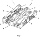
- Figure 1 shows a plastic pallet 1 with three runners 2, 2' on the underside 7 of the pallet 1, and a top side 4, wherein the middle runner 2' has a handle 3
- cavities 5 are provided in the middle runner 2' between the handle 3 and the surface 4 and between the handle 3 and the side walls 8 of the middle runner 2'. These spaces provide enough space to grasp the handle with the hand or with the fingers or, depending on the position of the hand, to completely enclose the handle.
- the handle 3 is elongated with slightly rounded edges and is arranged on the underside of the middle skid 2'.
- the orientation of the handle 3 runs parallel to the surface of the upper side and along the central longitudinal axis of the middle skid 2'.
- the handle 3 is arranged in the middle of the middle skid, at the geometric center of the pallet and as close as possible to the center of gravity of the pallet, close to the contact surface of the skid with the ground. This arrangement allows the easiest possible access to the handle, and the handle is easily grasped from the underside 7 of the pallet 1.
- the underside 7 of the plastic pallet 1 has a rib structure 6 with cavities to provide mechanical stability and a significant weight saving.
- Figure 2A shows a plastic pallet 1 as in Figure 1 described from a different perspective and with a different rib structure 6 on the underside 7.
- Figure 2B shows an excerpt from Figure 2A with the handle 3 and the cavities 5 to the side of the handle 3 between the handle 3 and the side walls 8 of the middle runner 2' and the cavity 5 between the handle 3 and the top side 4 (not shown) of the pallet 1.
- Figure 3 shows the plastic pallet as in Figure 2A described in another perspective view.
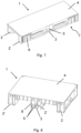
- Figure 4 shows a perspective of the top side 4 of the plastic pallet 1 with the three runners 2, 2'.
- the top side 4 has a closed surface.
- Figure 5 shows the top side 4 of the plastic pallet 1, as in Figure 4 shown, with a closed surface.
- the longitudinal axis is drawn along line AA and the transverse axis along line BB.
- Figure 6 is a cross section through the central longitudinal axis AA of the middle skid 2' of the plastic pallet 1 of the Figure 5
- the elongated handle 3 is arranged in the center of the central skid 2' along the central longitudinal axis AA on the underside 7 of the pallet 1.
- the cross-section shows the cavity 5 between the handle 3 and the upper side 4 of the pallet 1.
- the rib structures 6 and the cavities therebetween are visible.
- Figure 8 shows a cross section through the central transverse axis BB of pallet 1 of the Figure 5 in a perspective view.
- the handle 3 in the center of the middle skid 2' has a U-shaped cross-section with the opening of the U facing downwards.
- the two outer skids 2 and the cavities 5 between the handle 3 and the side walls 8 of the middle skid 2' and between the handle 3 and the top 4 of the pallet 1 are also shown. These cavities 5 provide sufficient space to grip the handle ergonomically.
- Figure 9 shows a bottom view of the underside 7 of the plastic pallet 1 with the two outer runners 2 and the middle runner 2', the elongated handle 3 and the rib structure 6 of the pallet 1. The orientation of the elongated handle 3 along the central longitudinal axis of the middle runner 2' is visible.
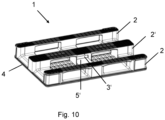
- FIG 10 A variant of a handle 3' is shown, not according to the invention.
- the handle 3' has a cylindrical shape and is arranged in the middle of the middle runner 2'.
- the elongated handle 3' is parallel to the surface 4 along the central longitudinal axis in the direction of the central longitudinal skid 2'.
- the circular-cylindrical handle 3' is arranged on a plane between the top side 4 of the pallet and the underside of the skid 2', and the lower surface of the underside of the central skid 2' is continuous.
- An opening to a cavity 5' for fingers is provided in the side wall of the central skid 2' for easier access to the handle 3'.
- the handle 3' can be grasped through the skids 2, 2' from the side of the underside of the pallet 1, which enables lateral removal of the pallet 1 from a stack.
Landscapes
- Engineering & Computer Science (AREA)
- Mechanical Engineering (AREA)
- Pallets (AREA)
Description
- Die Erfindung eine Kunststoffpalette mit Kufen.
- Paletten aus Kunststoff mit einem Handgriff sind beispielsweise aus
US2017297765A1 bekannt. Darin ist eine Palette mit mehreren Füssen und mehreren Griffen beschrieben, welche von der Unterseite der Palette gegriffen werden können. Die Griffe umfassen ein durchgehendes Loch mit Seitenwänden und mit einer Eingangsöffnung, die sich senkrecht zur Oberfläche der Palette und parallel zur kurzen Seite der Palette erstrecken. Die Griffe sind ausserhalb der Mitte der Palette und ausserhalb der Füsse angeordnet. - Des Weiteren wird in
EP2877408 eine Palette mit vier Füssen, einer Oberseite und einer Unterseite beschrieben, wobei die Oberseite im Zentrum ein Handzugangsloch aufweist, welches sich parallel zur kurzen Seite der Palette erstreckt. Dadurch kann von der Oberseite in das Loch gegriffen werden und die Palette getragen werden. Die Paletten sind stapelbar, indem die Füsse eine Öffnung aufweisen und die Füsse einer ersten Palette in die Öffnung der Füsse einer darauf gestapelten zweiten Palette eingreifen. - Zudem sind aus
US7856932 ,EP2067709 oderWO0078620 - Aus
US 2012/0037050 A1 ist eine Palette mit einem nicht flachen Deck, insbesondere für flexible Ladung, bekannt, welche durch das Einsetzen oder Anbringen von Verstärkungselementen verstärkt werden und ein Spannseil enthalten kann, das das Absinken des Oberdecks bei Beladung der Palette verhindert oder verringert. -
EP 0979778 A2 offenbart eine Palette mit verstärkten Eckstegwänden, bei welcher Belastungen und Schläge durch elastische Verformung der Eckstegwände eliminiert und zum Teil an die dahinter liegenden Bereiche der Palette verteilend abgeleitet werden. - Der vorliegenden Erfindung liegt nun die Aufgabe zugrunde, eine Kunststoffpalette mit Kufen anzugeben, welche eine optimierte einfache Handhabung für den Transport mit einer Hand erlaubt und es ermöglicht, die saubere Oberseite der Palette gegen den Körper hin zu tragen.
- Diese Aufgabe wird durch eine Kunststoffpalette nach Anspruch 1 gelöst. Die Palette weist eine mit Kufen versehene Unterseite und eine Oberseite auf, wobei eine Kufe entlang der Mitte der Kunststoffpalette verläuft und die Kufe entlang der Mitte der Palette einen Handgriff aufweist, welcher von der Unterseite der Palette greifbar ist. Die Kufe entlang der Mitte der Kunststoffpalette wird auch als mittlere Kufe bezeichnet, unabhängig davon, wie viele Kufen die Palette aufweist. Vorzugsweise weist die Kunststoffpalette drei Kufen auf, vorzugsweise drei Längskufen. Es ist aber auch möglich, dass die Kunststoffpalette zwei Kufen und drei Füsse aufweist oder dass sie drei Querkufen aufweist, oder dass sie mehr als drei Kufen, beispielsweise fünf Kufen aufweist.
- Der Handgriff ist in der Mitte der mittleren Kufe, relativ zur Länge und Breite der Palette, vorzugsweise entlang der zentralen Längsachse der mittleren Kufe angeordnet. Der Handgriff ist im geometrischen Mittelpunkt der Palette angeordnet. Besonders bevorzugt ist der Handgriff möglichst nahe am oder im Schwerpunkt der Palette angeordnet. Dadurch können auch schwerere Paletten mit einem Gewicht von 20 Kilogramm oder mehr mit einer Hand getragen werden.
- Die Anordnung des Handgriffs in der mittleren Kufe bezüglich der Höhe zwischen der Oberseite der Palette und der Unterseite der Kufe ist jedoch variabel. Vorzugsweise ist der Handgriff auf der Unterseite der mittleren Kufe angeordnet, möglichst nahe an der Fläche, die mit dem Boden in Kontakt käme. Dies ermöglicht einen möglichst einfachen und ergonomischen Zugang zum Handgriff von der Unterseite der Palette her.
- Unter dem Begriff "von der Unterseite greifbar" wird verstanden, dass der Handgriff der Palette entweder von unten oder von der Seite der Palette greifbar ist. Im Unterschied dazu ist der Handgriff von der Oberseite der Palette nicht greifbar.
- Der Handgriff ist länglich ausgebildet. Die Ausrichtung des Handgriffs verläuft idealerweise parallel zur Fläche der Oberseite, bevorzugt entlang der zentralen Längsachse der mittleren Kufe. Zwischen dem Handgriff und der Oberseite der Kunststoffpalette ist ein Hohlraum für Finger vorgesehen. Vorzugsweise ist die Öffnung zum Hohlraum in der unteren Fläche der mittleren Kufe, im Bereich der Fläche, welche mit dem Boden in Kontakt käme, angeordnet.
- In einer weiteren Ausführungsform ist die untere Fläche der mittleren Kufe durchgehend und der Handgriff ist parallel zur Oberseite der Palette und auf einer Ebene zwischen der Unterseite der mittleren Kufe und der Oberseite der Palette angeordnet. In dieser Ausführungsform befindet sich die Öffnung zum Hohlraum für Finger vorzugsweise in der Seitenwand der mittleren Kufe.
- Die Öffnung in der Seitenwand der mittleren Kufe ermöglicht das Greifen des Handgriffs von der Seite der Palette her, gegebenenfalls durch zusätzliche Öffnungen in der äusseren Kufe, was eine seitliche Entnahme der Palette ab einem Stapel ermöglicht. Die Seite der Palette wird ebenfalls zur Unterseite gezählt.
- Der längliche Handgriff weist einen U-förmigen Querschnitt auf mit vorzugsweise leicht abgerundeten Ecken. Durch die leicht abgerundeten Ecken wird ein hoher Tragekomfort für die Hand erreicht.
- Die Oberseite der Kunststoffpalette weist vorzugsweise eine durchgehend geschlossene Fläche auf. Dies ist möglich, weil sich der Handgriff in der Kufe auf der Unterseite der Palette befindet. Die geschlossene Fläche der Oberseite kann mit einer im Wesentlichen glatten Oberfläche versehen sein, damit die Palette leicht zu reinigen ist und keine Ansätze für Schmutz oder Bakterien bietet, weshalb sie sich auch für einen Einsatz im Hygiene- und Reinraumbereich eignet.
- Die Kunststoffpaletten werden aus einem strapazierfähigen und belastbaren Material, vorzugsweise aus einem oder mehreren Thermoplasten, hergestellt. Beispielsweise enthält das thermoplastische Material Polyethylen oder Polypropylen oder Mischungen davon. Zusätzlich kann die Kunststoffpalette Verstärkungen in verschiedenen Profilen aufweisen, beispielsweise Stahlprofile, insbesondere Stahlrohre. Die Verstärkungen zur Verstärkung der Kunststoffpaletten und zur Erhöhung der Traglast können beliebig angeordnet sein. Beispielsweise können Verstärkungsrohre entlang der Seiten der Palette, entlang der Kufen der Palette oder entlang aller vier Seiten angeordnet sein.
- Die erfindungsgemässe Kunststoffpalette hat den grossen Vorteil, dass durch den Handgriff auf der Unterseite die flächige Oberseite beim Tragen am Körper anliegt. Die Oberseite ist üblicherweise sauberer als die Unterseite mit den Kufen. Dies ist ein grosser Vorteil gegenüber Paletten mit Griffen auf der Oberseite der Palette, bei denen beim Tragen entweder ein Rand oder die verschmutzte Unterseite der Palette mit den Füssen oder Kufen gegen den Körper gedrückt wird, was unangenehm ist und mehr Kraft erfordert. Das Tragen der erfindungsgemässen Kunststoffpalette ist hingegen durch den Handgriff auf der Unterseite angenehm und erfordert weniger Kraft. Die Position des Handgriffs in der mittleren Kufe ermöglicht das Tragen der Palette mit nur einer Hand. Durch diese besondere Anordnung des Handgriffs können auch kleinere Menschen die Palette tragen. Ein weiterer Vorteil der vorliegenden Erfindung liegt darin, dass der Handgriff nahe am oder im Schwerpunkt der Palette angeordnet ist, was das Tragen der Palette ebenfalls vereinfacht.
- In einer weiteren Ausführungsform liegt zudem ein Vorteil darin, dass der Handgriff durch eine Öffnung in der Seitenwand der mittleren Kufe von der Seite der Palette greifbar ist und die seitliche Entnahme der Palette ab einem Stapel möglich ist.
- Kombinationen von zwei oder mehreren der oben aufgeführten Ausführungen und Varianten sind im Rahmen der beanspruchten Erfindung denkbar.
- Weitere Vorteile der Erfindung folgen aus der nachfolgenden Beschreibung, in welcher die Erfindung anhand von in den schematischen Zeichnungen dargestellten Ausführungsbeispielen näher erläutert wird.
- Es zeigen:
- Fig. 1
- eine Kunststoffpalette mit Handgriff in perspektivischer Darstellung auf die Unterseite der Palette,
- Fig. 2A
- die Kunststoffpalette mit Handgriff in einer weiteren perspektivischen Darstellung von schräg unten,
- Fig. 2B
- eine Detailansicht des Handgriffs der Kunststoffpalette der
Figur 2A , - Fig. 3
- eine weitere perspektivische Darstellung der Kunststoffpalette mit Handgriff von schräg unten,
- Fig. 4
- die Kunststoffpalette mit Handgriff in perspektivischer Darstellung von schräg oben,
- Fig. 5
- die Kunststoffpalette von
Figur 4 in einer Sicht von oben auf die Oberseite, - Fig. 6
- ein Querschnitt durch die zentrale Längsachse der mittleren Kufe der Kunststoffpalette entlang der Linie A-A der
Figur 5 , - Fig. 7
- ein Querschnitt durch die zentrale Längsachse der mittleren Kufe entlang der Linie A-A der
Figur 5 durch die Kunststoffpalette, - Fig. 8
- ein Querschnitt entlang der Linie B-B der
Figur 5 durch die Kunststoffpalette, - Fig. 9
- die Kunststoffpalette in einer Sicht von unten auf die Unterseite mit Kufen, und
- Fig. 10
- eine Kunststoffpalette mit einer nicht erfindungsgemäßen Variante eines Handgriffs in perspektivischer Darstellung von schräg unten.
- In den Figuren sind für dieselben Elemente jeweils dieselben Bezugszeichen verwendet und es gelten Erklärungen zu einem bestimmten Bezugszeichen für alle Figuren, wenn nicht ausdrücklich etwas anders erwähnt ist.
-
Figur 1 zeigt eine Kunststoffpalette 1 mit drei Kufen 2, 2' auf der Unterseite 7 der Palette 1, und einer Oberseite 4, wobei die mittlere Kufe 2' einen Handgriff 3 aufweist. Zudem sind in der mittleren Kufe 2' zwischen dem Handgriff 3 und der Oberfläche 4 und zwischen dem Handgriff 3 und den Seitenwänden 8 der mittleren Kufe 2' Hohlräume 5 vorgesehen. Diese Räume bieten genug Platz, um mit der Hand oder mit den Fingern den Handgriff zu fassen oder je nach Position der Hand den Handgriff ganz zu umschliessen. - Der Handgriff 3 ist länglich ausgebildet mit leicht abgerundeten Kanten und auf der Unterseite der mittleren Kufe 2' angeordnet. Die Ausrichtung des Handgriffs 3 verläuft parallel zur Fläche der Oberseite und entlang der zentralen Längsachse der mittleren Kufe 2'. Zudem ist der Handgriff 3 in der Mitte der mittleren Kufe im geometrischen Mittelpunkt der Palette und möglichst nahe am Schwerpunkt der Palette angeordnet, nahe an der Kontaktfläche der Kufe zum Boden. Diese Anordnung ermöglicht einen möglichst einfachen Zugang zum Handgriff, und der Handgriff ist von der Unterseite 7 der Palette 1 her leicht greifbar.
- Die Unterseite 7 der Kunststoffpalette 1 weist eine Rippenstruktur 6 mit Hohlräumen auf, um eine mechanische Stabilität und eine grosse Gewichtseinsparung zu bewirken.
-
Figur 2A zeigt eine Kunststoffpalette 1 wie inFigur 1 beschrieben aus einer anderen Perspektive und mit einer anderen Rippenstruktur 6 auf der Unterseite 7. -
Figur 2B zeigt einen Ausschnitt ausFigur 2A mit dem Handgriff 3 und den Hohlräumen 5 seitlich des Handgriffs 3 zwischen Handgriff 3 und den Seitenwänden 8 der mittleren Kufe 2' und dem Hohlraum 5 zwischen Handgriff 3 und Oberseite 4 (nicht gezeigt) der Palette 1. -
Figur 3 zeigt die Kunststoffpalette wie inFigur 2A beschrieben in einer weiteren perspektivischen Ansicht. -
Figur 4 zeigt eine Perspektive auf die Oberseite 4 der Kunststoffpalette 1 mit den drei Kufen 2, 2'. Die Oberseite 4 weist eine geschlossene Fläche auf. -
Figur 5 zeigt die Oberseite 4 der Kunststoffpalette 1, wie inFigur 4 gezeigt, mit einer geschlossenen Fläche. Zudem sind die Längsachse entlang der Linie A-A und die Querachse entlang der Linie B-B eingezeichnet. - In
Figur 6 ist ein Querschnitt durch die zentrale Längsachse A-A der mittleren Kufe 2' der Kunststoffpalette 1 derFigur 5 ersichtlich. Der längliche Handgriff 3 ist in der Mitte der mittleren Kufe 2' entlang der zentralen Längsachse A-A auf der Unterseite 7 der Palette 1 angeordnet. Der Querschnitt zeigt den Hohlraum 5 zwischen dem Handgriff 3 und der Oberseite 4 der Palette 1. Zusätzlich sind die Rippenstrukturen 6 und die dazwischenliegenden Hohlräume ersichtlich. -
Figur 7 zeigt einen Querschnitt durch die zentrale Längsachse A-A der Palette 1 derFigur 5 wie inFigur 6 beschrieben in einer perspektivischen Ansicht. Zusätzlich zuFigur 6 ist hier neben der mittleren Kufe 2' eine äussere Kufe 2 ersichtlich. -
Figur 8 zeigt einen Querschnitt durch die zentrale Querachse B-B der Palette 1 derFigur 5 in einer perspektivischen Ansicht. Der Handgriff 3 in der Mitte der mittleren Kufe 2' weist einen U-förmigen Querschnitt auf mit der Öffnung des U's nach unten. Die beiden äusseren Kufen 2 und die Hohlräume 5 zwischen dem Handgriff 3 und den Seitenwänden 8 der mittleren Kufe 2' und zwischen dem Handgriff 3 und der Oberseite 4 der Palette 1 sind ebenfalls dargestellt. Diese Hohlräume 5 bieten genügend Platz, um auf ergonomische Weise den Handgriff zu greifen. -
Figur 9 zeigt eine Unteransicht auf die Unterseite 7 der Kunststoffpalette 1 mit den zwei äusseren Kufen 2 und der mittleren Kufe 2', dem länglichen Handgriff 3 und der Rippenstruktur 6 der Palette 1. Die Ausrichtung des länglichen Handgriffs 3 entlang der zentralen Längsachse der mittleren Kufe 2' ist ersichtlich. - In der
Figur 10 ist eine nicht erfindungsgemäße Variante eines Handgriffs 3' dargestellt. Der Handgriff 3' weist eine zylinderförmige Form auf und ist in der Mitte der mittleren Kufe 2' angeordnet. InFigur 10 ist der längliche Handgriff 3' parallel zur Oberfläche 4 entlang der zentralen Längsachse in Richtung der mittleren Längskufe 2' angeordnet. Zudem ist der kreiszylinderförmige Handgriff 3' auf einer Ebene zwischen der Oberseite 4 der Palette und der Unterseite der Kufe 2' angeordnet, und die untere Fläche der Unterseite der mittleren Kufe 2' ist durchgehend. Es ist eine Öffnung zu einem Hohlraum 5' für Finger in der Seitenwand der mittleren Kufe 2' für einen erleichterten Zugang zum Handgriff 3' vorgesehen. In dieser Variante ist der Handgriff 3' durch die Kufen 2, 2' von der Seite der Unterseite der Palette 1 greifbar, was eine seitliche Entnahme der Palette 1 ab einem Stapel ermöglicht. -
- 1
- Kunststoffpalette
- 2
- Kufen, äussere Kufen
- 2'
- mittlere Kufe
- 3, 3'
- Handgriff
- 4
- Oberseite
- 5, 5'
- Hohlraum
- 6
- Rippenstruktur
- 7
- Unterseite
- 8
- Seitenwand der mittleren Kufe
Claims (5)
- Kunststoffpalette (1) mit einer mit Kufen (2, 2') versehenen Unterseite (7) und einer Oberseite (4), wobei eine Kufe eine mittlere Kufe (2') ist, die entlang der Mitte der Kunststoffpalette (1) verläuft, und wobei eine Kufe einen Handgriff (3) aufweist, welcher von der Unterseite (7) der Palette (1) greifbar ist, dadurch gekennzeichnet, dass die mittlere Kufe (2') den Handgriff (3) aufweist, wobei der Handgriff (3) in der Mitte der mittleren Kufe (2'), im geometrischen Mittelpunkt der Palette (1), relativ zur Länge und Breite der Palette (1), angeordnet ist, wobei der Handgriff (3) länglich ausgebildet ist und einen U-förmigen Querschnitt aufweist, und wobei zwischen dem Handgriff (3) und der Oberseite (4) der Kunststoffpalette (1) ein Hohlraum (5) für Finger vorgesehen ist, derart dass die Palette (1) mit einer Hand tragbar ist.
- Kunststoffpalette (1) nach Anspruch 1, dadurch gekennzeichnet, dass die Oberseite (4) der Palette (1) eine durchgehend geschlossene Fläche aufweist.
- Kunststoffpalette (1) nach einem der vorhergehenden Ansprüche, dadurch gekennzeichnet, dass der längliche Handgriff (3) parallel zur Fläche der Oberseite (4) der Palette (1) ausgerichtet ist.
- Kunststoffpalette (1) nach einem der vorhergehenden Ansprüche, dadurch gekennzeichnet, dass der Handgriff (3) entlang einer zentralen Längsachse der mittleren Kufe (2') ausgerichtet ist.
- Kunststoffpalette (1) nach einem der vorhergehenden Ansprüche, dadurch gekennzeichnet, dass die untere Fläche der mittleren Kufe (2') durchgehend ist und eine Öffnung zum Hohlraum (5) für Finger in der Seitenwand der mittleren Kufe (2') vorgesehen ist.
Applications Claiming Priority (2)
| Application Number | Priority Date | Filing Date | Title |
|---|---|---|---|
| CH01169/18A CH715381A1 (de) | 2018-09-26 | 2018-09-26 | Kunststoffpalette mit Handgriff. |
| PCT/IB2019/057773 WO2020065437A1 (de) | 2018-09-26 | 2019-09-16 | Kunststoffpalette mit handgriff |
Publications (2)
| Publication Number | Publication Date |
|---|---|
| EP3856653A1 EP3856653A1 (de) | 2021-08-04 |
| EP3856653B1 true EP3856653B1 (de) | 2025-07-02 |
Family
ID=68242784
Family Applications (1)
| Application Number | Title | Priority Date | Filing Date |
|---|---|---|---|
| EP19787442.3A Active EP3856653B1 (de) | 2018-09-26 | 2019-09-16 | Kunststoffpalette mit handgriff |
Country Status (7)
| Country | Link |
|---|---|
| US (1) | US11420791B2 (de) |
| EP (1) | EP3856653B1 (de) |
| CN (1) | CN112752717A (de) |
| CH (1) | CH715381A1 (de) |
| MX (1) | MX2021003488A (de) |
| PL (1) | PL3856653T3 (de) |
| WO (1) | WO2020065437A1 (de) |
Families Citing this family (2)
| Publication number | Priority date | Publication date | Assignee | Title |
|---|---|---|---|---|
| US11661237B1 (en) * | 2020-07-24 | 2023-05-30 | Formall, Inc. | Pallet assembly |
| CN113602630B (zh) * | 2021-09-10 | 2023-05-30 | 广东特帅科技股份有限公司 | 组合式塑胶栈板 |
Family Cites Families (36)
| Publication number | Priority date | Publication date | Assignee | Title |
|---|---|---|---|---|
| US5197395A (en) * | 1988-08-09 | 1993-03-30 | Pigott Maurice J | Plastic pallet with deck assembly |
| FR2705084B1 (fr) * | 1993-05-10 | 1995-07-28 | Delacour Frederic | Palette de manutention et son procédé de fabrication. |
| US5687652A (en) * | 1993-06-28 | 1997-11-18 | Ruma; Joseph G. | Oriented fiber reinforced monolithic plastic foam pallet |
| JP3943641B2 (ja) * | 1996-12-26 | 2007-07-11 | パレネット株式会社 | プラスチック製パレット |
| DE19836378C2 (de) * | 1998-08-11 | 2003-08-21 | Linpac Stucki Kunststoffverarb | Palette |
| JP4018265B2 (ja) * | 1998-11-11 | 2007-12-05 | 三甲株式会社 | 合成樹脂製パレット |
| US6357366B1 (en) * | 1999-02-05 | 2002-03-19 | Menasha Corporation | Rackable molded pallet |
| SE514427C2 (sv) | 1999-06-17 | 2001-02-19 | Pehrsson & Lindgren Ab | Lastpall samt metod att tillverka densamma |
| JP2002154542A (ja) * | 2000-11-15 | 2002-05-28 | Sanko Co Ltd | 合成樹脂製パレット |
| US6622641B2 (en) * | 2001-10-03 | 2003-09-23 | Rehrig Pacific Company | Pallet |
| DE202006001222U1 (de) * | 2006-01-24 | 2007-05-31 | Mauser-Werke Gmbh | Palette |
| JP2008056303A (ja) | 2006-08-31 | 2008-03-13 | Sanko Co Ltd | パレット |
| US20080141912A1 (en) * | 2006-12-19 | 2008-06-19 | Valentinsson Anders L | Transport pallet |
| US7856932B2 (en) | 2006-12-22 | 2010-12-28 | Coca-Cola Bottling Co. United, Inc. | Stackable packaged goods pallet |
| PL2067709T3 (pl) | 2007-12-06 | 2013-03-29 | Utz Georg Holding Ag | Dwuczęściowa płaska paleta |
| US8701569B2 (en) * | 2008-06-20 | 2014-04-22 | Oria Collapsibles, Llc | Pallet design with structural reinforcement |
| IL197105A0 (en) | 2009-02-18 | 2009-11-18 | B B P Technologies Ltd | A non-flat deck-board pallet |
| US20110120353A1 (en) * | 2009-09-22 | 2011-05-26 | Guy Jensen | Plastic rackable pallet |
| CN201808706U (zh) * | 2009-11-18 | 2011-04-27 | 王连山 | 新型便携式矿泉水桶 |
| CH702628A2 (de) * | 2010-02-01 | 2011-08-15 | Utz Georg Holding Ag | Kunststoffpalette. |
| US9038546B2 (en) * | 2010-07-13 | 2015-05-26 | Meppp B.V. | Plastic pallet |
| GB2504087A (en) | 2012-07-16 | 2014-01-22 | Chep Uk Ltd | Pallet with feet which nest when stacking |
| CN202728686U (zh) * | 2012-09-14 | 2013-02-13 | 天威新能源控股有限公司 | 铝质粘胶托盘 |
| US9611071B2 (en) * | 2013-03-14 | 2017-04-04 | Rehrig Pacific Company | Delivery and merchandising system |
| US10377527B2 (en) * | 2015-06-22 | 2019-08-13 | Bastian Solutions, Llc | Composite concrete pallet |
| US10479553B2 (en) | 2016-02-26 | 2019-11-19 | Rehrig Pacific Company | Nestable pallet |
| CN109649785A (zh) * | 2017-08-04 | 2019-04-19 | 安徽宽居电器有限公司 | 一种塑胶托盘 |
| CN107472639A (zh) * | 2017-08-04 | 2017-12-15 | 安徽宽居电器有限公司 | 一种塑胶栈板 |
| US10589897B1 (en) * | 2017-08-11 | 2020-03-17 | Paxxal Inc. | Roto molded pallet |
| US10737832B2 (en) * | 2018-04-05 | 2020-08-11 | Rehrig Pacific Company | Half pallet |
| US20190337673A1 (en) * | 2018-05-03 | 2019-11-07 | Brian O'Connell | Pallet |
| EP3587295B1 (de) * | 2018-06-27 | 2021-03-17 | Schoeller Allibert GmbH | Adapterelement und transportpalette mit adapterelementen |
| US20200031522A1 (en) * | 2018-07-25 | 2020-01-30 | Paxxal Inc. | Roto molded pallet |
| US11111053B2 (en) * | 2018-11-13 | 2021-09-07 | Chep Technology Pty Limited | Stackable half-size reconfigurable pallet/dolly platform |
| US11174070B2 (en) * | 2019-08-07 | 2021-11-16 | Rehrig Pacific Company | Stackable pallet |
| US11040799B1 (en) * | 2020-01-23 | 2021-06-22 | Monoflo International, Inc. | Pallet with impact resistance |
-
2018
- 2018-09-26 CH CH01169/18A patent/CH715381A1/de unknown
-
2019
- 2019-09-16 WO PCT/IB2019/057773 patent/WO2020065437A1/de not_active Ceased
- 2019-09-16 CN CN201980062863.2A patent/CN112752717A/zh active Pending
- 2019-09-16 EP EP19787442.3A patent/EP3856653B1/de active Active
- 2019-09-16 US US17/278,877 patent/US11420791B2/en active Active
- 2019-09-16 PL PL19787442.3T patent/PL3856653T3/pl unknown
- 2019-09-16 MX MX2021003488A patent/MX2021003488A/es unknown
Also Published As
| Publication number | Publication date |
|---|---|
| US11420791B2 (en) | 2022-08-23 |
| US20220041330A1 (en) | 2022-02-10 |
| CH715381A1 (de) | 2020-03-31 |
| CN112752717A (zh) | 2021-05-04 |
| WO2020065437A1 (de) | 2020-04-02 |
| MX2021003488A (es) | 2021-06-18 |
| EP3856653A1 (de) | 2021-08-04 |
| PL3856653T3 (pl) | 2025-09-01 |
Similar Documents
| Publication | Publication Date | Title |
|---|---|---|
| EP3636559B1 (de) | Stapelbare kiste | |
| DE4341256A1 (de) | Durchlüftete Palette | |
| EP0919483A1 (de) | Kunststoffpalette | |
| EP3880570A1 (de) | Kunststoffpalette mit geschützten kufen | |
| EP0301445A2 (de) | Flachpalette | |
| EP3856653B1 (de) | Kunststoffpalette mit handgriff | |
| EP2216255B1 (de) | Kunststoff-Palette mit verstärkter Kufe | |
| DE9218718U1 (de) | Teilpalette | |
| EP3188975A1 (de) | Ladegutträger | |
| EP4146552B1 (de) | Kunststoffpalette mit schnappverbindung | |
| WO2005019048A1 (de) | Nestbarer ladungsträger | |
| CH686360A5 (de) | Lager- und Transportbehaelter aus Kunststoff. | |
| EP1919787A1 (de) | Palette mit hoher formstabilität und tragkraft | |
| EP1582470B1 (de) | Transportkasten aus Kunststoff für schweres Transportgut | |
| EP0258549A2 (de) | Stapelbarer Flaschenkasten | |
| DE102005026112B4 (de) | Transportkasten aus Kunststoff | |
| DE7214505U (de) | Palette | |
| EP3012205B1 (de) | Teilbarer flaschenkasten | |
| CH697133A5 (de) | Lagerbehälter. | |
| DE2820967A1 (de) | Palette in nicht schachtelbarer ausbildung | |
| DE202016105908U1 (de) | Vorrichtung zum Transport von Gegenständen | |
| EP0835817A2 (de) | Stapelbarer Behälter, insbesondere Lager- und Transportbehälter sowie Behältersystem | |
| EP3626646A1 (de) | Stapelbare kiste | |
| DE29900044U1 (de) | Kasten aus Kunststoff | |
| DE29608417U1 (de) | Stapelbarer Kunststoffbehälter für die Lagerung und den Transport von Gutstücken, insbesondere Käselaiben |
Legal Events
| Date | Code | Title | Description |
|---|---|---|---|
| STAA | Information on the status of an ep patent application or granted ep patent |
Free format text: STATUS: UNKNOWN |
|
| STAA | Information on the status of an ep patent application or granted ep patent |
Free format text: STATUS: THE INTERNATIONAL PUBLICATION HAS BEEN MADE |
|
| PUAI | Public reference made under article 153(3) epc to a published international application that has entered the european phase |
Free format text: ORIGINAL CODE: 0009012 |
|
| STAA | Information on the status of an ep patent application or granted ep patent |
Free format text: STATUS: REQUEST FOR EXAMINATION WAS MADE |
|
| 17P | Request for examination filed |
Effective date: 20210315 |
|
| AK | Designated contracting states |
Kind code of ref document: A1 Designated state(s): AL AT BE BG CH CY CZ DE DK EE ES FI FR GB GR HR HU IE IS IT LI LT LU LV MC MK MT NL NO PL PT RO RS SE SI SK SM TR |
|
| DAV | Request for validation of the european patent (deleted) | ||
| DAX | Request for extension of the european patent (deleted) | ||
| STAA | Information on the status of an ep patent application or granted ep patent |
Free format text: STATUS: EXAMINATION IS IN PROGRESS |
|
| 17Q | First examination report despatched |
Effective date: 20230213 |
|
| GRAP | Despatch of communication of intention to grant a patent |
Free format text: ORIGINAL CODE: EPIDOSNIGR1 |
|
| STAA | Information on the status of an ep patent application or granted ep patent |
Free format text: STATUS: GRANT OF PATENT IS INTENDED |
|
| INTG | Intention to grant announced |
Effective date: 20250324 |
|
| GRAS | Grant fee paid |
Free format text: ORIGINAL CODE: EPIDOSNIGR3 |
|
| GRAA | (expected) grant |
Free format text: ORIGINAL CODE: 0009210 |
|
| STAA | Information on the status of an ep patent application or granted ep patent |
Free format text: STATUS: THE PATENT HAS BEEN GRANTED |
|
| AK | Designated contracting states |
Kind code of ref document: B1 Designated state(s): AL AT BE BG CH CY CZ DE DK EE ES FI FR GB GR HR HU IE IS IT LI LT LU LV MC MK MT NL NO PL PT RO RS SE SI SK SM TR |
|
| REG | Reference to a national code |
Ref country code: GB Ref legal event code: FG4D Free format text: NOT ENGLISH |
|
| REG | Reference to a national code |
Ref country code: CH Ref legal event code: EP |
|
| REG | Reference to a national code |
Ref country code: DE Ref legal event code: R096 Ref document number: 502019013564 Country of ref document: DE |
|
| REG | Reference to a national code |
Ref country code: IE Ref legal event code: FG4D Free format text: LANGUAGE OF EP DOCUMENT: GERMAN |
|
| REG | Reference to a national code |
Ref country code: CH Ref legal event code: U11 Free format text: ST27 STATUS EVENT CODE: U-0-0-U10-U11 (AS PROVIDED BY THE NATIONAL OFFICE) Effective date: 20251001 |
|
| PGFP | Annual fee paid to national office [announced via postgrant information from national office to epo] |
Ref country code: DE Payment date: 20250919 Year of fee payment: 7 |
|
| REG | Reference to a national code |
Ref country code: NL Ref legal event code: MP Effective date: 20250702 |
|
| PG25 | Lapsed in a contracting state [announced via postgrant information from national office to epo] |
Ref country code: PT Free format text: LAPSE BECAUSE OF FAILURE TO SUBMIT A TRANSLATION OF THE DESCRIPTION OR TO PAY THE FEE WITHIN THE PRESCRIBED TIME-LIMIT Effective date: 20251103 |
|
| PG25 | Lapsed in a contracting state [announced via postgrant information from national office to epo] |
Ref country code: NL Free format text: LAPSE BECAUSE OF FAILURE TO SUBMIT A TRANSLATION OF THE DESCRIPTION OR TO PAY THE FEE WITHIN THE PRESCRIBED TIME-LIMIT Effective date: 20250702 |
|
| PG25 | Lapsed in a contracting state [announced via postgrant information from national office to epo] |
Ref country code: IS Free format text: LAPSE BECAUSE OF FAILURE TO SUBMIT A TRANSLATION OF THE DESCRIPTION OR TO PAY THE FEE WITHIN THE PRESCRIBED TIME-LIMIT Effective date: 20251102 |
|
| PG25 | Lapsed in a contracting state [announced via postgrant information from national office to epo] |
Ref country code: NO Free format text: LAPSE BECAUSE OF FAILURE TO SUBMIT A TRANSLATION OF THE DESCRIPTION OR TO PAY THE FEE WITHIN THE PRESCRIBED TIME-LIMIT Effective date: 20251002 |
|
| REG | Reference to a national code |
Ref country code: LT Ref legal event code: MG9D |
|
| PG25 | Lapsed in a contracting state [announced via postgrant information from national office to epo] |
Ref country code: FI Free format text: LAPSE BECAUSE OF FAILURE TO SUBMIT A TRANSLATION OF THE DESCRIPTION OR TO PAY THE FEE WITHIN THE PRESCRIBED TIME-LIMIT Effective date: 20250702 |
|
| PG25 | Lapsed in a contracting state [announced via postgrant information from national office to epo] |
Ref country code: HR Free format text: LAPSE BECAUSE OF FAILURE TO SUBMIT A TRANSLATION OF THE DESCRIPTION OR TO PAY THE FEE WITHIN THE PRESCRIBED TIME-LIMIT Effective date: 20250702 |
|
| PG25 | Lapsed in a contracting state [announced via postgrant information from national office to epo] |
Ref country code: GR Free format text: LAPSE BECAUSE OF FAILURE TO SUBMIT A TRANSLATION OF THE DESCRIPTION OR TO PAY THE FEE WITHIN THE PRESCRIBED TIME-LIMIT Effective date: 20251003 |
|
| PGFP | Annual fee paid to national office [announced via postgrant information from national office to epo] |
Ref country code: CH Payment date: 20251001 Year of fee payment: 7 |
|
| PG25 | Lapsed in a contracting state [announced via postgrant information from national office to epo] |
Ref country code: SE Free format text: LAPSE BECAUSE OF FAILURE TO SUBMIT A TRANSLATION OF THE DESCRIPTION OR TO PAY THE FEE WITHIN THE PRESCRIBED TIME-LIMIT Effective date: 20250702 Ref country code: CZ Free format text: LAPSE BECAUSE OF FAILURE TO SUBMIT A TRANSLATION OF THE DESCRIPTION OR TO PAY THE FEE WITHIN THE PRESCRIBED TIME-LIMIT Effective date: 20250702 |
|
| PG25 | Lapsed in a contracting state [announced via postgrant information from national office to epo] |
Ref country code: LV Free format text: LAPSE BECAUSE OF FAILURE TO SUBMIT A TRANSLATION OF THE DESCRIPTION OR TO PAY THE FEE WITHIN THE PRESCRIBED TIME-LIMIT Effective date: 20250702 |
|
| PG25 | Lapsed in a contracting state [announced via postgrant information from national office to epo] |
Ref country code: BG Free format text: LAPSE BECAUSE OF FAILURE TO SUBMIT A TRANSLATION OF THE DESCRIPTION OR TO PAY THE FEE WITHIN THE PRESCRIBED TIME-LIMIT Effective date: 20250702 |
|
| PG25 | Lapsed in a contracting state [announced via postgrant information from national office to epo] |
Ref country code: RS Free format text: LAPSE BECAUSE OF FAILURE TO SUBMIT A TRANSLATION OF THE DESCRIPTION OR TO PAY THE FEE WITHIN THE PRESCRIBED TIME-LIMIT Effective date: 20251002 |
|
| PG25 | Lapsed in a contracting state [announced via postgrant information from national office to epo] |
Ref country code: ES Free format text: LAPSE BECAUSE OF FAILURE TO SUBMIT A TRANSLATION OF THE DESCRIPTION OR TO PAY THE FEE WITHIN THE PRESCRIBED TIME-LIMIT Effective date: 20250702 |
|
| PG25 | Lapsed in a contracting state [announced via postgrant information from national office to epo] |
Ref country code: RO Free format text: LAPSE BECAUSE OF FAILURE TO SUBMIT A TRANSLATION OF THE DESCRIPTION OR TO PAY THE FEE WITHIN THE PRESCRIBED TIME-LIMIT Effective date: 20250702 |
|
| PG25 | Lapsed in a contracting state [announced via postgrant information from national office to epo] |
Ref country code: SM Free format text: LAPSE BECAUSE OF FAILURE TO SUBMIT A TRANSLATION OF THE DESCRIPTION OR TO PAY THE FEE WITHIN THE PRESCRIBED TIME-LIMIT Effective date: 20250702 |
|
| PG25 | Lapsed in a contracting state [announced via postgrant information from national office to epo] |
Ref country code: DK Free format text: LAPSE BECAUSE OF FAILURE TO SUBMIT A TRANSLATION OF THE DESCRIPTION OR TO PAY THE FEE WITHIN THE PRESCRIBED TIME-LIMIT Effective date: 20250702 |
|
| PG25 | Lapsed in a contracting state [announced via postgrant information from national office to epo] |
Ref country code: IT Free format text: LAPSE BECAUSE OF FAILURE TO SUBMIT A TRANSLATION OF THE DESCRIPTION OR TO PAY THE FEE WITHIN THE PRESCRIBED TIME-LIMIT Effective date: 20250702 |