EP3856672B1 - Procédé de planification et, au moins partiellement, d'installation d'un ascenseur dans une cage d'ascenseur - Google Patents
Procédé de planification et, au moins partiellement, d'installation d'un ascenseur dans une cage d'ascenseur Download PDFInfo
- Publication number
- EP3856672B1 EP3856672B1 EP19762996.7A EP19762996A EP3856672B1 EP 3856672 B1 EP3856672 B1 EP 3856672B1 EP 19762996 A EP19762996 A EP 19762996A EP 3856672 B1 EP3856672 B1 EP 3856672B1
- Authority
- EP
- European Patent Office
- Prior art keywords
- elevator shaft
- elevator
- automated
- installation
- shaft
- Prior art date
- Legal status (The legal status is an assumption and is not a legal conclusion. Google has not performed a legal analysis and makes no representation as to the accuracy of the status listed.)
- Active
Links
Images




Classifications
-
- B—PERFORMING OPERATIONS; TRANSPORTING
- B66—HOISTING; LIFTING; HAULING
- B66B—ELEVATORS; ESCALATORS OR MOVING WALKWAYS
- B66B19/00—Mining-hoist operation
-
- B—PERFORMING OPERATIONS; TRANSPORTING
- B66—HOISTING; LIFTING; HAULING
- B66B—ELEVATORS; ESCALATORS OR MOVING WALKWAYS
- B66B19/00—Mining-hoist operation
- B66B19/002—Mining-hoist operation installing or exchanging guide rails
Definitions
- the invention relates to a method for planning and at least partially installing an elevator system in an elevator shaft according to claim 1.
- Installation steps such as installing a component within an elevator shaft, have traditionally been performed by fitters or installation personnel.
- a fitter goes to a location within the elevator shaft where the component is to be installed and installs the component at a desired location, for example, by drilling holes in a shaft wall and securing the component to the shaft wall with screws or bolts inserted into these holes.
- the fitter may use tools and/or machines to do this.
- individual installation steps can be automated, for example, by an automated assembly device.
- the assembly device can, for example, drill holes at specified positions on the shaft walls of the elevator shaft and insert anchor bolts into the drilled holes.
- the following steps, such as aligning and attaching guide rails using rail brackets and the aforementioned anchor bolts, can then be performed by an installer.
- Rail brackets usually have a lower rail bracket section and an upper rail bracket section that can be screwed to the lower rail bracket section.
- the lower rail bracket section is fixed to the shaft wall. For example, screwed on.
- the guide rail is connected to the upper rail bracket section, which can be moved relative to the lower rail bracket section. This allows the guide rail to be aligned.
- the division of labor between the automated assembly device and the installer can vary.
- the WO 2017/016783 A1 describes an automated assembly device for performing an installation process in an elevator shaft of an elevator system and a method for performing an installation process using such an assembly device.
- a support component with a mechatronic installation component is fixed in the elevator shaft at various heights.
- the installation component performs various installation steps, such as drilling holes in a shaft wall of the elevator shaft.
- WO 2017/016783 A1 focuses mainly on the implementation of the installation and does not deal in detail with its planning.
- the EP 1 225 522 A1 describes a design system for an elevator product to be manufactured based on a specific order.
- the EP 3 127 847 A1 describes a device and a method for determining the position of an installation platform in an elevator shaft.
- the WO 2017/016780 A1 describes an automated assembly device for performing an installation process in an elevator shaft of an elevator system and a method for performing an installation process using such an assembly device.
- this method before drilling a hole in a shaft wall of the elevator shaft, an image of the position of reinforcements within the shaft wall is created, and based on this image, drilling positions for the boreholes are determined.
- the object of the invention is, in particular, to propose a method for planning and at least partially installing an elevator system in an elevator shaft, which enables the installation to be carried out as planned. According to the invention, this object is achieved by a method having the features of claim 1.
- verifying that the automated installation steps can be performed by the assembly device ensures that the planned automated installation steps can actually be carried out. Ensuring the feasibility of the planned automated installation steps is also helped by planning the automated installation steps only after the actual layout of the elevator system has been derived. This allows changes from the target layout to the actual layout of the elevator system to be taken into account when planning the automated installation steps.
- the installation of the The elevator system is continued by one or more technicians.
- the technician aligns guide rails and secures them to the shaft walls, installs a drive, assembles a car, and performs all necessary electrical installations. It is also possible for individual installation steps to be performed by another automated assembly device.
- the assembly device performs several installation steps automatically. It can perform a single installation step, such as drilling a hole in a shaft wall, multiple times at different locations in the elevator shaft, or it can perform several installation steps, such as drilling a hole and inserting an anchor bolt into the hole. Even if different installation steps are performed, they are often performed multiple times at different locations in the elevator shaft.
- the assembly device has, in particular, a carrier component and a mechatronic installation component.
- the carrier component is designed to be displaced relative to the elevator shaft, i.e., for example, within the elevator shaft, and to be positioned at different heights within the elevator shaft.
- the installation component is held on the carrier component and designed to carry out an installation step within the installation process at least partially automatically, preferably fully automatically.
- the installation component is designed, for example, as an industrial robot.
- the assembly device has, in particular, a displacement device, by means of which the carrier component can be displaced in the elevator shaft, and a fixing component for fixing, in particular caulking, the carrier component in the elevator shaft.
- the assembly device has, in particular, a control device for controlling the individual components of the assembly device.
- the assembly device is, for example, configured according to a WO 2017/016783 A1 described assembly device.
- Deriving a target layout for the elevator system from the target dimensions of the elevator shaft is primarily performed by a planner, who is supported in particular by a special computer-aided planning tool. This derivation can also be carried out fully automatically using a corresponding computer-aided tool.
- the starting point for deriving the target layout are the target dimensions of the elevator shaft, such as the width, depth, and height of the elevator shaft, the number of floors, and the dimensions of door cutouts.
- the target dimensions of the elevator shaft can be taken from construction plans of the building containing the elevator shaft. It is also possible for the target dimensions of the elevator shaft to be derived from a digital building model of the corresponding building.
- the target layout of the elevator system specifies, for example, the arrangement of a counterweight (next to or behind the elevator car), the size of the elevator car, the type and number of guide rails, the arrangement and design of the drive machine, and the type and design of any support means (e.g., steel cables or belts).
- the target layout can have a lower level of detail than the actual layout subsequently derived from it. For example, it is possible that the target layout only specifies the arrangement of the counterweight and the size of the elevator car.
- the determination of the installation steps to be carried out by an automated assembly device is also carried out by a planner. However, this step can also be fully automated. In this context, the planner also specifies which assembly device should be used to carry out the automated installation steps.
- the planner's particular task is to plan the installation of the elevator system so that it can be carried out as quickly and/or cost-effectively as possible.
- different installation steps can be carried out automatically. For example, in some cases it may be advantageous to only drill holes for fixing guide rails and insert the corresponding anchor bolts automatically; in other cases it may be advantageous to drill holes automatically and fix so-called rail bracket bases for fixing guide rails to the shaft wall using corresponding screws.
- the determination of the automated installation steps also depends on the available automated assembly devices. There may be different versions of mounting devices that can perform at least partially different installation steps. It is also possible For example, due to the dimensions of the elevator shaft, only a specific version of the mounting device can be used, which can also influence the determination of the automated installation steps.
- the automated installation steps can be defined independently of the target layout of the elevator system. This is the case, for example, if the same installation steps are always performed automatically for all possible elevator system layouts. For example, it can be specified that holes are always drilled by an automated assembly device, and that the assembly device always inserts anchor bolts into the drilled holes. Thus, only adopting this specification is necessary to define the automated installation steps.
- the dimensions of the intended automated assembly device are compared with the dimensions of the elevator shaft.
- the assembly device is designed to be flexible enough, for example, that a fixing component for fixing the support component can be adapted to different dimensions of the elevator shaft within certain limits. Such adaptations are planned or specified, in particular, within the scope of this process step.
- the installation component can reach all necessary locations in the elevator shaft.
- the check to determine whether the automated installation steps can be carried out by the assembly device is carried out, in particular, based on the target dimensions of the elevator shaft and the target layout of the elevator system.
- the aforementioned inspection is carried out based on the actual dimensions of the elevator shaft and the actual layout of the elevator system. It is not absolutely necessary that the above-mentioned test is carried out on the basis of the target layout of the elevator system.
- the process steps described so far can be carried out based on the target dimensions of the elevator shaft and thus independently of the actual elevator shaft in which the elevator system is to be installed.
- the recording of some actual dimensions of the elevator shaft must be carried out at or in the elevator shaft.
- the actual dimensions can be recorded manually by a planner or installer, for example.
- the planner or installer measures the width and depth of the elevator shaft at different heights and/or checks whether the dimensions of the door cutouts correspond to the target specifications. It is also possible to measure the entire elevator shaft using an automated measuring system.
- the measuring system can, for example, be designed like a WO 2018/041815 A1
- the measuring system described above must be implemented.
- the aim of the recording or measurement is to determine any deviations from the nominal dimensions of the elevator shaft.
- the dimensions of the elevator shaft can also include surface properties, particularly the shaft walls, or holes and local elevations in the shaft walls.
- the dimensions of the elevator shaft here also include the layout of reinforcements in the shaft walls of the elevator shaft. This means that when recording actual dimensions, the layout of reinforcements can also be detected and documented using a suitable sensor, for example, integrated into a digital model of the elevator shaft.
- the derivation of an actual layout of the elevator system from the target layout of the elevator system and the recorded actual dimensions of the elevator shaft is also carried out by a planner, a fitter, or fully automatically.
- the goal is to adopt the target layout as the actual layout of the elevator system.
- it is checked whether the target layout can be implemented in the real elevator shaft defined by the actual dimensions. For example, it is checked whether the planned size of the elevator car is compatible with the actual dimensions of the elevator shaft.
- the check can, for example, include all specifications of the target or actual layout. If this is the case, the target layout is adopted as the actual layout of the elevator shaft. If this is not the case, adjustments to the layout are made according to the actual dimensions of the elevator shaft.
- the size of the Elevator cabin can be adapted.
- all other specifications of the target or actual layout can also be adjusted. If the automated assembly device requires reference elements to determine its position in the elevator shaft, for example, in the form of cords stretched in the elevator shaft, their position is also determined in this process step.
- the assembly device is removed from the elevator shaft and the installation is continued, in particular by a fitter, by hand or with the assistance of tools.
- the planners or fitters mentioned can be a single person or several different people.
- a digital model of the elevator shaft is created using the recorded actual dimensions of the elevator shaft. This allows for a particularly accurate derivation of the actual layout from the target layout of the elevator system.
- the actual layout of the elevator system can be integrated into the digital model of the elevator shaft and thus mapped particularly accurately.
- a digital model of an elevator shaft is specifically understood to mean a CAD model of the elevator shaft, which may also contain additional information.
- the level of detail of the digital model of the elevator shaft can vary. For example, only a few dimensions of the elevator shaft may be measured by hand, and the digital model created based on these. However, it is also possible for the entire elevator shaft to be measured very precisely using an automated measuring system, and for the digital model to be derived from the resulting point cloud.
- the digital model of the elevator shaft can be integrated into a digital building model and blueprints of the building containing the elevator shaft.
- a further check is performed to determine whether the automated installation steps can be performed by the assembly device. This constitutes a second check of the feasibility of the automated installation steps. This particularly reliably ensures that the automated installation steps can actually be performed. Feasibility is ensured even if the actual layout of the elevator system differs from the target layout.
- the assembly device uses a suitable sensor to check, before carrying out an upcoming installation step, whether the installation step can be carried out as planned.
- a suitable sensor for example a laser scanner for distance measurement or a sensor for detecting reinforcements in a shaft wall.
- This sensor is used to more closely examine the intended position at which the installation step is to be carried out, for example, a hole is to be drilled and a rail bracket base is to be mounted.
- the laser scanner it can be checked, for example, whether there are any local unevennesses, such as holes or edges, in the shaft wall at the intended position that could make the planned implementation of the installation step difficult or impossible.
- the sensor for reinforcement detection can be used, for example, to check whether there is reinforcement at the intended position that would prevent a hole from being drilled at the intended location. Positioning is difficult or impossible.
- the positioning of the sensor and the evaluation of the acquired sensor data are carried out primarily by the control device of the mounting device.
- the installation step will be carried out as planned. If the feasibility check is negative, the implementation will be rescheduled so that the installation step can be carried out, and the rescheduled installation step will then be carried out as planned. This ensures the feasibility of the installation step with particular certainty.
- the intended position for the installation step is shifted within permissible limits so that the installation step can be carried out.
- the intended position is shifted so that a detected reinforcement no longer interferes with the drilling of a hole.
- additional installation step for example, a raised area at the specified location can be removed using a chisel, allowing the originally planned installation step to be carried out without being affected by the raised area.
- an installer in the event that replanning while adhering to specified specifications is not possible, can specify the implementation of the installation step and start the execution. The installer can then, using his experience, decide that implementation of the installation step is justifiable even without adhering to the specified specifications.
- a specified specification can, for example, be that in a certain
- the installation device would only automatically carry out the installation step of drilling a hole in the shaft wall if this requirement is met. However, if reinforcement is present, for example, at the edge of the specified area, the installer can decide to take the risk that the drilling might not be successful and drill the hole in the intended position anyway.
- the installer can adapt the implementation process to the one planned by the installation facility. This allows them to contribute their experience to the implementation process.
- the installer can change the sequence and initiate the installation step directly via an input on the control device of the assembly device. It is also possible for the control device of the assembly device to have an interface through which the installer can remotely access the control device, for example, via a mobile phone app, and change the sequence and initiate the installation step.
- the digital model of the elevator shaft is adjusted using the sensor data acquired by the sensor. This enables the creation of a particularly accurate digital model of the elevator shaft.
- the type of adjustment depends on the type of sensor used. If distances to the shaft wall were measured using the sensor, the masses of the elevator shaft contained in the digital shaft model are adjusted locally. If reinforcements in a shaft wall were detected using the sensor, the information about the reinforcements is incorporated into the digital model of the elevator shaft.
- an assembly protocol is automatically created for the automatically performed installation steps.
- the assembly log can be viewed as part of the model of the elevator shaft and thus a building model of the corresponding building. This means that the installation is logged and documented without any additional effort.
- the assembly log can, for example, be evaluated and used for subsequent installation steps carried out by an installer. For example, the installer can use the assembly log to obtain information about which automated installation steps require manual rework.
- the assembly log can also be saved for documentation purposes.
- the assembly log is created in particular by the control device of the assembly device and saved in such a way that it can be retrieved later.
- the assembly log contains, for example, information about the exact positions at which the installation steps were carried out and/or about the successful or unsuccessful completion of the automated installation steps.
- a simulation of the automated installation step is carried out. This makes it possible to check particularly precisely whether the planned automated installation steps can actually be carried out.
- a computer-aided simulation tool is used in which the assembly device and the elevator shaft are modeled.
- a simulation of the individual automated installation steps is then carried out.
- a planner or an automated system can check whether the installation steps can actually be carried out or whether, for example, there are collisions between the installation component and the elevator shaft or the support component.
- the insertion of the assembly device into the elevator shaft can also be simulated.
- a position is determined by a marker located on the elevator shaft.
- the markers can be located in the elevator shaft or in or directly next to the Door cutouts of the elevator shaft. The recording and evaluation of these markings can also be advantageously carried out independently of the procedural steps for planning and at least partially installing an elevator system in an elevator shaft.
- the markings can, for example, indicate building axes, particularly a vertical axis. Based on the building axes identified by the marking, the digital model of the elevator shaft can be correctly aligned. It is also possible for the aforementioned marking to indicate a defined height, for example, a so-called meter mark. The meter mark indicates a vertical distance of 1 m from the top edge of the finished floor. From this, for example, the correct position of an elevator shaft door can be determined very precisely.
- a reinforcement plan of the elevator shaft walls is taken into account when deriving a target layout for the elevator system. This allows the target layout to be derived in such a way that as few problems as possible arise with the reinforcements in the shaft walls during installation of the elevator system.
- a reinforcement plan contains information about the locations and, in particular, the depth at which reinforcements run in the shaft walls. The target layout is thus defined, for example, so that no holes need to be drilled where reinforcements are present.
- reinforcing bars run vertically in shaft walls, which are connected to horizontal reinforcing bars in the ceiling area by means of special brackets.
- the guide rails are defined in the target layout in such a way that no rail bracket bases need to be fixed to the shaft walls in the ceiling area.
- the guide rails can have a length that corresponds approximately to the distance between the ceilings of the building in which the elevator shaft is located. The guide rails can then be fixed in such a way that they always abut one another in the area of a ceiling of the building.
- the mounting device is arranged in the elevator shaft in a first installation phase.
- a position of the mounting device is determined using a reference element arranged in the elevator shaft, and the mounting device carries out automated installation steps.
- a fitter aligns guide rails of the elevator system to an alignment element arranged in the elevator shaft and then fixes them in place.
- a course of the alignment element is determined based on a course of the reference element and the actual layout of the elevator system, and information on the course of the alignment element is made available to the fitter. This allows the fitter to arrange the alignment element in the elevator shaft very quickly and without having to measure the elevator shaft.
- two reference elements are used in the first installation phase and two alignment elements are used in the second installation phase, all of which are designed in particular as cords and run mainly in a main extension direction of the elevator shaft.
- the main direction of extension of the elevator shaft is understood here to be the direction in which an elevator car of the fully assembled elevator system travels.
- the main direction of extension is therefore generally vertical, but it can also be inclined relative to the vertical or horizontal.
- the main direction of extension does not necessarily have to run along a single straight line along the entire length of the elevator shaft.
- the main direction of extension can also be composed of straight sections, the transition areas of which can also be rounded.
- the position of the mounting device, in particular of the carrier component can, for example, be determined according to a WO 2017/167719 A1
- the alignment of the guide rails to the alignment elements can be determined, for example, according to a method described in WO 2015/091419 A1 described procedures.
- Information about the alignment element's path can be provided to the installer in a variety of ways. For example, distances between the alignment element and the reference element can be output for two different heights, which can then be manually adjusted and measured. A special gauge can also be used for setting the specified distances. If both the reference element and the alignment element are exactly vertical, outputting the specified distances is only sufficient for one height.
- the installation component can be used to apply appropriate markings to a shaft wall or to a component additionally fixed to the shaft wall, such as a suitable angle plate. These markings can be used to position the alignment element.
- the described determination and provision of information on the course of the reference element can also be advantageously carried out independently of the procedural steps for planning and at least partial installation of an elevator system in an elevator shaft.
- information about the current status of the assembly device can be retrieved via an interface of a control device of the assembly device. This allows the assembly device to be monitored and any problems to be detected.
- the information mentioned may, for example, include information on whether the assembly device is currently performing an installation step or is inactive. It may, for example, include the current position of the support component in the elevator shaft or Information about the installation steps already performed and/or pending is retrieved.
- the information is retrieved remotely, for example, via a communications network, particularly the Internet or a local Wi-Fi network.
- the information can be retrieved, for example, via an app running on a mobile phone.
- the control device of the automated assembly device informs a responsible technician via the aforementioned interface. For this purpose, a notification is actively sent to the technician. This immediately informs the responsible technician of an error and eliminates the need to constantly check the status of the assembly device to detect the occurrence of an error.
- This information or notification can, for example, be displayed by an app on the technician's mobile phone and/or the app can emit an audible alarm. Such notifications are also known as push notifications.
- control device of the assembly device can be remotely controlled via an interface.
- Remote control of the assembly device can be advantageous, for example, if the assembly device has gotten itself into a situation from which it cannot escape, for example, because any possible action would violate some specification.
- the remote control can be carried out, for example, by an installer using the app mentioned above.
- the remote control can be used to start or stop an installation step, activate or deactivate the fixation of the support component, or relocate the support component in the elevator shaft.
- the described query of information about the current status of the assembly device and the described procedural steps based on it, such as informing about errors or remote control of the control device, are also independent of the procedural steps for planning and at least partial Installation of an elevator system in an elevator shaft can be carried out advantageously.
- an automated assembly device which can perform automated installation steps in an elevator shaft of an elevator system.
- a mounting device 14 is shown arranged in a lift shaft 10 of an elevator system 12, by means of which rail bracket lower parts 16 can be fixed to a shaft wall 18.
- the lift shaft 10 extends in a main extension direction 11, which in the Fig. 1 vertically aligned.
- the rail bracket bases 16 can be used to Fig. 1 guide rails not shown (46 in Figs. 3 and 4 ) of the elevator system 12 to the shaft wall 18.
- the mounting device 14 has a support component 20 and a mechatronic installation component 22.
- the support component 20 is designed as a frame on which the mechatronic installation component 22 is mounted.
- This frame has dimensions that allow the support component 20 to be mounted within the To move the elevator shaft 10 vertically, i.e., for example, to different vertical positions on different floors within a building.
- the mechatronic installation component 22 is designed as an industrial robot 24, which is attached to the frame of the support component 20 in a downwardly suspended manner. An arm of the industrial robot 24 can be moved relative to the support component 20 and, for example, moved toward the shaft wall 18 of the elevator shaft 10.
- the support component 20 is connected via a steel cable serving as a support means 26 to a displacement component 28 in the form of a motor-driven cable winch, which is attached to a stop 29 on the ceiling of the elevator shaft 10 at the top of the elevator shaft 10.
- a displacement component 28 in the form of a motor-driven cable winch, which is attached to a stop 29 on the ceiling of the elevator shaft 10 at the top of the elevator shaft 10.
- the mounting device 14 further comprises a fixing component 30, by means of which the support component 20 can be fixed or caulked within the elevator shaft 10 in the lateral direction, i.e. in the horizontal direction.
- two reference elements 13 in the form of cords are stretched along its entire length, aligned along the main extension direction 11.
- the reference elements 13 are installed in the elevator shaft 10 by a fitter and serve to determine the position of the mounting device 14, specifically the position of the support component 20 in the elevator shaft 10.
- Fig. 2 shows an enlarged view of a mounting device 14 without the displacement component 28.
- the support component 20 is designed as a cage-like frame in which several horizontally and vertically extending beams form a mechanically resilient structure. Attached to the top of the cage-like support component 20 are retaining cables 32, which can be connected to the support means 26.
- the mechatronic installation component 22 is implemented using an industrial robot 24.
- the industrial robot 24 is equipped with multiple robot arms that can pivot about pivot axes.
- the industrial robot can have at least six degrees of freedom, meaning that an assembly tool 34 guided by the industrial robot 24 can be moved with six degrees of freedom, meaning, for example, with three rotational degrees of freedom and three translational degrees of freedom.
- the industrial robot can be implemented as a vertical articulated-arm robot, a horizontal articulated-arm robot, a SCARA robot, or a Cartesian robot or gantry robot.
- the robot can be coupled to various assembly tools 34 at its cantilevered end.
- the assembly tools 34 can differ in terms of their design and intended use.
- the assembly tools 34 can be held on the support component 20 in such a way that the cantilevered end of the industrial robot 24 can be moved toward them and coupled to one of them.
- the industrial robot 24 can, for example, have a tool changing system that is designed to enable the handling of at least several such assembly tools 34.
- One of the assembly tools 34 is designed as a sensor in the form of a laser scanner, by means of which the relative position of the carrier component 20 with respect to the reference elements 13 can be determined. This can be carried out, for example, using a method which is described in the WO 2017/167719 A1 is described.
- the position of the support component 20 in the elevator shaft 10 can be determined from the relative position of the support component 20 with respect to the reference elements 13. Based on the position of the support component 20, it can be determined at which points on the shaft wall 18 a rail bracket lower part 16 is to be attached.
- One of the assembly tools 34 is designed as a reinforcement detection sensor, by means of which reinforcements or their position in the shaft walls 18 can be detected or determined.
- the reinforcement detection sensor can be moved along a shaft wall 18 by the industrial robot 24.
- One of the assembly tools 34 is designed as a drilling tool, similar to a drill, By coupling the industrial robot 24 with such a drilling tool, the installation component 22 can be configured to enable at least partially automated, controlled drilling of fastening holes in one of the shaft walls 18 of the elevator shaft 10.
- the drilling tool can be moved and handled by the industrial robot 24 in such a way that the drilling tool, with a drill bit, drills holes into the shaft wall 18 of the elevator shaft 10 at a predetermined position, into which fastening elements in the form of screws, screw anchors, or anchor bolts are later inserted to fix the rail bracket bases 16.
- a further assembly tool 34 is designed as a screwdriver in order to screw screw anchors or screws into previously drilled fastening holes in the shaft wall 18 of the elevator shaft 10, at least semi-automatically.
- a further assembly tool 34 is designed as an impact tool, for example in the form of a hammer, in order to at least partially automatically drive anchor bolts into previously drilled fastening holes in the shaft wall 18 of the elevator shaft 10.
- a further assembly tool 34 is designed as a gripper in order to at least partially automatically fasten a rail bracket lower part 16 to the shaft wall 18.
- a further assembly tool 34 is designed as a marking tool, for example in the form of a milling cutter, for applying a marking to the shaft wall 18 or to a component mounted on a shaft wall 18, for example a rail bracket base 16.
- This marking can be used in a later installation step, particularly one carried out by an installer, for aligning, for example, alignment elements or guide rails.
- An assembly device does not need to include all of the described types of tools 34.
- a screwdriver for screwing screws into drilled holes and a gripper for gripping rail bracket bases are not necessary.
- a magazine component 36 may also be provided on the support component 20.
- the magazine component 36 may serve to store rail bracket bases 16 to be installed and to provide them to the installation component 22.
- Screw anchors, screws, or anchor bolts may also be stored and provided in the magazine component 36, which can be inserted into prefabricated mounting holes in the shaft wall 18 using the installation component 22.
- the industrial robot 24 can, for example, automatically grab a screw from the magazine component 36 and, for example, use an assembly tool 34 designed as a screwdriver to partially screw it into previously drilled fastening holes in the shaft wall 18.
- An assembly tool 34 can then be changed on the industrial robot 24 and, for example, a rail bracket lower part 16 can be grabbed from the magazine component 36.
- the rail bracket lower part 16 has fastening slots.
- the assembly tool 34 designed as a screwing device can be reconfigured and the screws tightened.
- the industrial robot 24 can pick up anchor bolts from the magazine component 36 and, using an assembly tool 34 designed as an impact tool, drive them into previously drilled mounting holes in the shaft wall 18.
- an assembly tool 34 designed as an impact tool
- a fitter can manually fix the rail bracket bases to the shaft wall 18 in a later installation step.
- the elevator system and its installation in the elevator shaft must be planned before installation begins.
- the starting point for planning the elevator system is the target dimensions of the elevator shaft, which can be found, for example, in construction plans or a digital building model of the building in which the elevator system is to be installed. Using the blueprints, the target values for the width, depth, and height of the elevator shaft, the number of floors, and the dimensions of the elevator shaft door cutouts can be determined. From these target dimensions of the elevator shaft, a planner derives a target layout for the elevator system with the help of a computer-aided tool.
- a counterweight (next to or behind the elevator car), the size of the elevator car, the type and number of guide rails, the arrangement and design of the drive motor, and the type and design of any suspension device (e.g., steel cables or belts).
- any suspension device e.g., steel cables or belts.
- FIGs. 3 and 4 A very simplified diagram of a target layout of an elevator system 12 is shown.
- the dimensions of an elevator car 40 (only in Fig. 3 shown), the arrangement of a counterweight 42, the positions of guide rails 46 and the positions of rail brackets 48 are specified.
- the positions of the door cutouts 44 In addition to the dimensions of the elevator shaft 10, particular attention is paid to the positions of the door cutouts 44.
- the planner When deriving the target layout of the elevator system, the planner particularly considers a reinforcement plan for the elevator shaft walls.
- the reinforcement plan contains information about the locations and, in particular, the depth at which reinforcements are installed in the shaft walls.
- the planner defines the target layout in such a way that no holes need to be drilled where reinforcements are present.
- the planner then defines the automated installation steps, i.e., the installation steps that are to be performed by an automated assembly device.
- the selection of the automated installation steps depends on a variety of factors.
- the planner also determines which assembly device is to be used to carry out the automated installation steps. Firstly, the planner must consider which automated assembly devices are actually available at the time of installation. are available.
- the desired layout of the elevator system plays a major role, especially the height of the elevator shaft. Since installing an automated assembly device in an elevator shaft involves a certain amount of effort, the elevator shaft should have a certain minimum height to make the use of an automated assembly device worthwhile. Since many factors play a role in selecting the automated installation steps, no generally applicable rules can be given.
- the planner checks that the automated installation steps can be carried out by the intended automated assembly device.
- the dimensions of the intended automated assembly device are compared with the dimensions of the elevator shaft. This checks whether the assembly device can be brought into the elevator shaft, whether the support component can be relocated with the installation component in the elevator shaft, and whether it is possible to fix the support component in the elevator shaft.
- the assembly device can be designed to be flexible enough that the fixing component for securing the support component can be adapted to different dimensions of the elevator shaft within certain limits. Such adjustments are planned or specified by the planner as part of this process step.
- the planner simulates the automated installation steps. He uses a computer-aided simulation tool that models the assembly device and the elevator shaft. The planner checks whether the installation steps can actually be carried out and whether there are any collisions between the installation component and the elevator shaft or the support component. In addition to simulating the automated installation steps, he also simulates the insertion of the assembly device into the elevator shaft.
- some actual dimensions of the elevator shaft are recorded. This step can therefore only be performed once the elevator shaft has been created.
- the recording of the actual dimensions of the elevator shaft can be carried out in a variety of ways. First, the planner or an installer can record some dimensions manually. This involves measuring the width and depth of the elevator shaft and the dimensions of the door cutouts at different heights.
- a measuring system 110 is shown during the measurement of an elevator shaft 10.
- the optical inertial measuring system 110 is suspended via a support means in the form of a cable 111 and a displacement device in the form of a winch 112 from a shaft ceiling 113 of a shaft head 114 of a mainly cuboid elevator shaft 10.
- the elevator shaft 10 runs in a vertically oriented main extension direction 11 and has a total of four shaft walls, wherein in the side view of Fig. 1 only a rear shaft wall 117 and a front shaft wall 118 are shown.
- the front shaft wall 118 has a total of three door cutouts 44, which are arranged one above the other in the main extension direction 11.
- Shaft doors will be installed in the door cutouts 44 at a later time, closing off the elevator shaft 10 and providing access to an elevator car.
- the elevator shaft 10 Opposite the shaft head 114, the elevator shaft 10 has a shaft pit 120, which is closed off by a shaft floor 121.
- the measuring system 110 has a camera system in the form of a digital stereo camera 122 with a first camera 122a and a second camera 122b.
- the stereo camera 122 is arranged on a primarily cuboid-shaped base body 123 of the measuring system 110 such that, in the suspended state shown, it is oriented vertically downwards toward the shaft floor 120.
- the stereo camera 122 is designed such that, in the state shown, it can capture sections of all four shaft walls.
- the stereo camera 122 is signal-connected to an evaluation unit 124 of the measuring system 110, which receives and evaluates the images captured by the stereo camera 122.
- the evaluation unit 124 searches the images for prominent points, such as corners or elevations in one of the shaft walls.
- the camera 122a, 122b can determine the position of the prominent point relative to the cameras 122a, 122b and thus relative to the measuring system 110 by means of triangulation, based on the known distance between the two cameras 122a, 122b and the different positions of the prominent point in both images.
- An inertial measuring unit 125 is arranged on the base body 123 of the measuring system 110 between the two cameras 122a, 122b.
- the inertial measuring unit 125 has three acceleration sensors (not shown), each arranged perpendicular to one another, and three yaw rate sensors (also not shown), arranged perpendicular to one another, which are used to determine the accelerations in the x-, y-, and z-directions and the rotational accelerations about the x-, y-, and z-axes. From the measured accelerations, the inertial measuring unit 125 can estimate its position and thus also the position of the measuring system 110 from a starting position and transmit this information to the evaluation unit 124 of the measuring system 110. It is also possible that the inertial measuring unit 125 only transmits the measured accelerations to the evaluation unit 124 and the evaluation unit 124 estimates the position of the measuring system 110 therefrom.
- the measuring system 110 is coupled to a position-determining unit 126.
- the position-determining unit 126 has a position information carrier in the form of a code tape 127, aligned in the main extension direction 11, which is stretched between the shaft floor 121 and the shaft ceiling 113.
- the code tape 127 has invisible magnetic code marks that represent information about the position in the main extension direction 11.
- the position-determining unit 126 also has a reading unit 128 arranged laterally on the base body 123 of the measuring system 110, through which the code tape 127 is passed.
- the reading unit 128 reads information in the form of the magnetic code marks of the code tape 127 and can thus very precisely determine the position of the reading unit 128 and thus of the measuring system 110 in the main extension direction 11.
- the information read from the code tape 127 can thus be regarded as additional information about the position of the measuring system 110 in the main extension direction 11 compared to the information from the acceleration and yaw rate sensors of the inertial measuring unit 125.
- the position of the measuring system 110 in the main extension direction 11 determined by means of the position determination unit 126 is regarded as the correct position of the measuring system 110 and thus replaces the position estimated by means of the inertial measuring unit 125. Position of the measuring unit 110 in the main extension direction. However, it is also possible to assume an average of the two positions mentioned as the correct position.
- the evaluation unit 124 determines the absolute position of the prominent point. The evaluation unit 124 thus determines the positions of a plurality of prominent points. To measure the entire elevator shaft 10, the measuring system 110 is moved by the winch 112 from top to bottom in the elevator shaft 10.
- the measuring system 110 also determines the positions of markings 129 on the elevator shaft 10.
- a marking 129 is located on a shaft wall in the area of each door cutout 44.
- the markings 129 are designed as so-called meter lines, which indicate a distance of one meter from the subsequent floor covering.
- further markings can be Fig. 5 Markings (not shown) may be arranged on the elevator shaft, which can be detected and evaluated by the measuring system 110. These markings may, for example, indicate building axes, in particular a vertical building axis.
- a so-called point cloud is created from the positions of the numerous landmarks, with each point in the point cloud corresponding to one of the landmarks. From this point cloud, and possibly taking into account the positions of the aforementioned markers, a digital model in the form of a CAD model of elevator shaft 10 is later derived. The digital model then contains the actual dimensions of elevator shaft 10.
- the planner After recording the actual dimensions of the elevator shaft, the planner derives an actual layout of the elevator system from the target layout and the recorded actual dimensions of the elevator shaft. The planner primarily checks whether there are any deviations between the target dimensions and the actual dimensions of the elevator shaft that make it impossible to adopt the target layout as the actual layout of the elevator system. If this is not the case, the planner adopts the target layout as the actual layout of the elevator system. Otherwise, the planner modifies the target layout to obtain an actual layout that the actual dimensions of the elevator shaft.
- the planner After deriving the actual layout of the elevator system, the planner checks again, in particular, that the automated installation step can be performed by the intended assembly device. This check is carried out analogously to the check described above.
- the installer then starts the automated installation steps.
- the interaction and communication between the installer and the automated assembly device is very schematic in the Fig. 6
- the installer 50 can initiate the automated installation steps directly via an input on a control device 52 of the automated assembly device.
- the installer 50 can access the control device 52 via a mobile phone 54, a communications network 56, such as the Internet or a local WLAN, and an interface 58 of the control device 52 and, for example, initiate the installation steps.
- the installer 50 can also use this method to query information about the current status of the assembly device.
- the information mentioned may include, for example, whether the assembly device is currently performing an installation step or is inactive. For example, the current position of the support component in the elevator shaft or information about the installation steps already performed and/or upcoming ones can be queried.
- the installer 50 is informed by the control device 52 via the interface 58, the communication network 56, and the mobile phone 54.
- the control device 52 sends a notification, a so-called push message, to the mobile phone 54 of the installer 50.
- the installer 50 can remotely control the control device 52 via the aforementioned method.
- the remote control can be used to start or stop a specific installation step, activate or deactivate the fixation of the support component, or relocate the support component in the elevator shaft.
- the assembly device automatically performs the automated installation steps.
- the assembly device uses a suitable sensor to check whether the installation step can be carried out as planned.
- the installation component of the assembly device incorporates a sensor for detecting reinforcements and checks the intended position for reinforcements. The positioning of the sensor and the evaluation of the recorded sensor data are carried out by the control unit of the assembly device.
- the installation step will be carried out as planned. If the feasibility check is negative, the implementation will be rescheduled so that the installation step can be carried out, and the rescheduled installation step will then be executed.
- the control unit of the assembly device performs a local replanning of the installation step.
- the planned position for the installation step is shifted within permissible limits so that the installation step can be carried out.
- the planned position is shifted so that a detected reinforcement no longer interferes with the drilling of a hole.
- the detection of reinforcement and the determination of drilling positions can be carried out, for example, as described in the WO 2017/016782 A1 described.
- the installer can specify the execution of the installation step and start the execution.
- a specified specification may, for example, be that there must be no reinforcement in the shaft wall in a certain area around a planned drilling position.
- the installation device would only automatically execute the installation step, namely drilling a hole in the shaft wall, if this specification is met.
- reinforcement is present, for example, at the edge of the specified area, the installer can decide to take the risk that the drilling might not be successful and the hole will still be drilled at the intended position.
- the necessary communication between the installer and the control device of the installation device runs in particular as in connection with Fig. 6 described.
- the digital model of the elevator shaft is adjusted using the sensor data acquired by the sensor. If reinforcements in a shaft wall are detected by the sensor, the information about the reinforcements is incorporated into the digital model of the elevator shaft. Additionally, information about completed installation steps, such as the position and type of holes drilled in shaft walls, is incorporated into the digital model of the elevator shaft.
- the control unit of the assembly device automatically creates an assembly log for the automated installation steps.
- the assembly log contains, for example, information about the exact positions at which which the installation steps were performed and/or about the successful or unsuccessful completion of the installation steps.
- the assembly device 12 determines the position of the support component 20 by means of reference elements 13 arranged in the elevator shaft 10.
- the phase in which the assembly device 12 carries out the automated installation steps can be referred to as a first installation phase.
- the installation of the elevator system is carried out manually by a technician in a second installation phase.
- the guide rails must be aligned and fixed to a shaft wall.
- the technician can use alignment elements arranged in the elevator shaft and designed as cords.
- the correct course of the alignment elements can be derived directly from the course of the aforementioned reference elements.
- the necessary information is provided to the technician by the control device of the installation device. This can also be done as in connection with Fig. 6 Based on this information, the installer can install the alignment elements in the elevator shaft during the second installation phase and before aligning the guide rails.
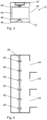
- FIGs. 7 and 8 An example is shown of the information that can be made available to the installer.
- Figs. 7 and 8 two reference elements 13 are shown in the area of a door cutout 44 of the elevator shaft 10, wherein the Fig. 7 shows the situation at a height h1 near the shaft head 114 of the elevator shaft 10.
- an alignment element 60 is arranged in the area of each guide rail 46.
- the alignment elements 60 are spaced from the associated reference elements 13 in the x and y directions by x0h1 and y0h1, or x1h1 and y1h1. The distances x0h1, y0h1, x1h1, and y1h1 are provided to the installer.
- the distances x0h0, y0h0, x1h0, and y1h0 are determined in a similar manner and provided to the installer. With these distances x0h0, y0h0, x1h0, y1h0, x0h1, y0h1, x1h1 and y1h1 as well as the information about the heights h0 and h1, the installer can correctly install the alignment elements 60 in the elevator shaft 10 and then align the guide rails 46 therewith.
Landscapes
- Lift-Guide Devices, And Elevator Ropes And Cables (AREA)
Claims (15)
- Procédé permettant la planification et l'installation au moins partielle d'un système d'ascenseur (12) dans une cage d'ascenseur (10), dans lequel des étapes d'installation automatisées sont exécutées par un dispositif de montage automatisé (14) et le procédé comprenant les étapes de procédé suivantes :- déduction d'une disposition théorique du système d'ascenseur (12) à partir de dimensions théoriques de la cage d'ascenseur,- définition des étapes d'installation à exécuter par un dispositif de montage automatisé (14),- vérification que les étapes d'installation automatisées peuvent être exécutées par le dispositif de montage (14),- collecte de quelques dimensions réelles de la cage d'ascenseur (10),- déduction d'une disposition réelle du système d'ascenseur (12) à partir de la disposition théorique du système d'ascenseur (12) et des dimensions réelles collectées de la cage d'ascenseur (10),- planification des étapes d'installation automatisées sur la base de la disposition réelle du système d'ascenseur (12) et- exécution des étapes d'installation automatisées avec le dispositif de montage (14).
- Procédé selon la revendication 1,
caractérisé en ce
qu'un modèle numérique de la cage d'ascenseur (10) est créé avec les dimensions réelles collectées de la cage d'ascenseur (10). - Procédé selon la revendication 1 ou 2,
caractérisé en ce
qu'après la déduction de la disposition réelle du système d'ascenseur (12), on vérifie encore une fois que les étapes d'installation automatisées peuvent être exécutées par le dispositif de montage (14). - Procédé selon la revendication 1, 2 ou 3,
caractérisé en ce que
le dispositif de montage (14) vérifie, avant l'exécution d'une étape d'installation imminente, à l'aide d'un capteur approprié (34), si l'étape d'installation peut être exécutée comme planifié et- si le résultat de la vérification est positif, exécute l'étape d'installation comme prévu,- si le résultat de la vérification est négatif, planifie de nouveau l'exécution de manière à ce que l'étape d'installation puisse être réalisée et l'exécute ensuite de cette manière. - Procédé selon la revendication 4,
caractérisé en ce que
dans le cas où une nouvelle planification n'est pas possible en respectant des spécifications établies, un monteur (50) peut définir l'exécution de l'étape d'installation et commencer l'exécution. - Procédé selon la revendication 4 ou 5,
caractérisé en ce que
le modèle numérique de la cage d'ascenseur (10) est adapté à l'aide des données de capteur collectées par ledit capteur (34). - Procédé selon l'une des revendications 1 à 6,
caractérisé en ce
qu'un protocole de montage est créé de manière automatisée pour les étapes d'installation exécutées de manière automatisée. - Procédé selon l'une des revendications 1 à 7,
caractérisé en ce que
lors de la vérification qu'une étape d'installation automatisée peut être exécutée par le dispositif de montage (14), une simulation de l'étape d'installation automatisée est exécutée. - Procédé selon l'une des revendications 1 à 8,
caractérisé en ce que
lors de la collecte des dimensions réelles de la cage d'ascenseur (10), une position est déterminée par un repère (129) disposé sur la cage d'ascenseur (10). - Procédé selon l'une des revendications 1 à 9,
caractérisé en ce que
lors de la déduction d'une disposition théorique du système d'ascenseur (12), un plan d'armature de parois de cage (18) de la cage d'ascenseur (10) est pris en compte. - Procédé selon l'une des revendications 1 à 10,
caractérisé en ce quedans une première phase d'installation- le dispositif de montage (14) est disposé dans la cage d'ascenseur (10),- une position du dispositif de montage (14) est déterminée à l'aide d'un élément de référence (13) disposé dans la cage d'ascenseur (10) et- le dispositif de montage (14) exécute des étapes d'installation automatisées, dans une seconde phase d'installation, après avoir retiré le dispositif de montage (14) de la cage d'ascenseur (10)- des rails de guidage (46) du système d'ascenseur (12) sont alignés par un monteur (50) sur un élément d'alignement (60) disposé dans la cage d'ascenseur (10) et sont ensuite fixés,dans lequel, dans la première phase d'installation, un tracé de l'élément d'alignement (60) est déterminé sur la base d'un tracé de l'élément de référence (13) et de la disposition réelle du système d'ascenseur (12) et des informations concernant le tracé de l'élément d'alignement (60) sont mises à la disposition du monteur (50). - Procédé selon l'une des revendications 1 à 11,
caractérisé en ce que
des informations sur un état actuel du dispositif de montage (14) peuvent être demandées par l'intermédiaire d'une interface (58) d'un dispositif de commande (52) du dispositif de montage (14). - Procédé selon la revendication 12,
caractérisé en ce
qu'en cas d'apparition d'une erreur dans le dispositif de montage automatisé (14), un monteur compétent (50) est informé par le dispositif de commande (52) du dispositif de montage automatisé (14) par l'intermédiaire de ladite interface (58). - Procédé selon la revendication 12 ou 13,
caractérisé en ce que
des informations sur des étapes d'installation automatisées terminées et/ou imminentes peuvent être demandées par l'intermédiaire de ladite interface (58) du dispositif de commande (52) du dispositif de montage (14). - Procédé selon la revendication 12, 13 ou 14,
caractérisé en ce
qu'un dispositif de commande (52) du dispositif de montage (14) peut être commandé à distance par l'intermédiaire de l'interface (58).
Applications Claiming Priority (2)
| Application Number | Priority Date | Filing Date | Title |
|---|---|---|---|
| EP18196895 | 2018-09-26 | ||
| PCT/EP2019/074016 WO2020064316A1 (fr) | 2018-09-26 | 2019-09-10 | Procédé pour la planification et l'installation au moins partielle d'un système d'ascenseur dans une cage d'ascenseur |
Publications (2)
| Publication Number | Publication Date |
|---|---|
| EP3856672A1 EP3856672A1 (fr) | 2021-08-04 |
| EP3856672B1 true EP3856672B1 (fr) | 2025-04-30 |
Family
ID=63685735
Family Applications (1)
| Application Number | Title | Priority Date | Filing Date |
|---|---|---|---|
| EP19762996.7A Active EP3856672B1 (fr) | 2018-09-26 | 2019-09-10 | Procédé de planification et, au moins partiellement, d'installation d'un ascenseur dans une cage d'ascenseur |
Country Status (5)
| Country | Link |
|---|---|
| US (1) | US11708244B2 (fr) |
| EP (1) | EP3856672B1 (fr) |
| CN (1) | CN112689608B (fr) |
| AU (1) | AU2019345881A1 (fr) |
| WO (1) | WO2020064316A1 (fr) |
Families Citing this family (7)
| Publication number | Priority date | Publication date | Assignee | Title |
|---|---|---|---|---|
| WO2019206644A1 (fr) * | 2018-04-24 | 2019-10-31 | Inventio Ag | Système de détermination de position et procédé pour déterminer une position d'une cabine d'ascenseur |
| WO2020234005A1 (fr) * | 2019-05-21 | 2020-11-26 | Inventio Ag | Dispositif d'alignement et procédé pour aligner un rail de guidage d'une installation d'ascenseur au moyen d'impulsions de force |
| CN114667264B (zh) * | 2019-11-12 | 2024-07-30 | 因温特奥股份公司 | 用于在竖井中移位和固定的装配框架 |
| CN113620147B (zh) | 2020-05-09 | 2024-07-30 | 奥的斯电梯公司 | 在建筑物的建造过程中使用的跃升电梯系统和跃升方法 |
| JP7027507B1 (ja) * | 2020-11-10 | 2022-03-01 | 東芝エレベータ株式会社 | レール設置支援装置、レール設置支援方法、レール設置支援システムおよびレール設置支援プログラム |
| EP4387914A1 (fr) * | 2021-08-20 | 2024-06-26 | KONE Corporation | Procédé et système de mesure pour modélisation tridimensionnelle d'une cage d'ascenseur |
| DE102024132336A1 (de) * | 2024-11-06 | 2025-11-06 | Tk Elevator Innovation And Operations Gmbh | Fahrkorb, Aufzugsanlage und Verfahren zum Betreiben der Aufzugsanlage |
Family Cites Families (13)
| Publication number | Priority date | Publication date | Assignee | Title |
|---|---|---|---|---|
| US4977983A (en) | 1989-10-26 | 1990-12-18 | Otis Elevator Company | Mount system for elevator guide rails |
| JP3877492B2 (ja) | 1999-08-31 | 2007-02-07 | 株式会社日立製作所 | 遠隔受注設計システムおよびエレベータ遠隔受注設計方法 |
| JP4249006B2 (ja) | 2003-12-17 | 2009-04-02 | 三菱電機ビルテクノサービス株式会社 | エレベータのガイドレール搭載用移動作業床 |
| FI123925B (fi) * | 2012-08-17 | 2013-12-13 | Kone Corp | Menetelmä hissiin liittyvän tiedon hallinnoinnissa |
| CN105829234B (zh) | 2013-12-19 | 2018-02-16 | 因温特奥股份公司 | 用于安装电梯设备的方法以及装置 |
| JP6322544B2 (ja) | 2014-10-21 | 2018-05-09 | 株式会社日立ビルシステム | 据付図作成装置、据付図作成方法及び据付図作成プログラム |
| US10850946B2 (en) | 2015-07-24 | 2020-12-01 | Inventio Ag | Automated mounting device for performing assembly jobs in an elevator shaft of an elevator system |
| EP3127847B1 (fr) | 2015-08-07 | 2017-12-20 | KONE Corporation | Dispositif et procede pour mesurer la position d'une plate-forme d'installation dans une cage d'ascenseur |
| JP6869999B2 (ja) | 2016-03-31 | 2021-05-12 | インベンテイオ・アクテイエンゲゼルシヤフトInventio Aktiengesellschaft | リフトシステムのリフトシャフト内で設置作業を実行するための方法および取付装置 |
| EP3445697B1 (fr) | 2016-04-20 | 2020-01-22 | Inventio AG | Dispositif et procede de montage destine a executer une procedure d'installation dans une cabine d'ascenseur |
| AU2017318398B2 (en) * | 2016-08-30 | 2020-10-01 | Inventio Ag | Method for analysis, and measurement system for measuring an elevator shaft of an elevator system |
| US11167956B2 (en) | 2016-11-24 | 2021-11-09 | Inventio Ag | Method for mounting and alignment device for aligning a guide rail of an elevator system |
| PL3580428T3 (pl) * | 2017-02-08 | 2021-06-14 | Inventio Ag | Sposób mocowania uchwytu do szyn układu dźwigu oraz układu dźwigu |
-
2019
- 2019-09-10 EP EP19762996.7A patent/EP3856672B1/fr active Active
- 2019-09-10 CN CN201980059499.4A patent/CN112689608B/zh active Active
- 2019-09-10 WO PCT/EP2019/074016 patent/WO2020064316A1/fr not_active Ceased
- 2019-09-10 US US17/250,658 patent/US11708244B2/en active Active
- 2019-09-10 AU AU2019345881A patent/AU2019345881A1/en not_active Abandoned
Also Published As
| Publication number | Publication date |
|---|---|
| AU2019345881A1 (en) | 2021-03-11 |
| EP3856672A1 (fr) | 2021-08-04 |
| US11708244B2 (en) | 2023-07-25 |
| CN112689608A (zh) | 2021-04-20 |
| US20210300729A1 (en) | 2021-09-30 |
| CN112689608B (zh) | 2023-02-21 |
| WO2020064316A1 (fr) | 2020-04-02 |
Similar Documents
| Publication | Publication Date | Title |
|---|---|---|
| EP3856672B1 (fr) | Procédé de planification et, au moins partiellement, d'installation d'un ascenseur dans une cage d'ascenseur | |
| EP3507227B1 (fr) | Procede d'analyse et systeme de mesure destine a mesurer une cage d'ascenseur | |
| EP3436390B1 (fr) | Dispositif et procede de montage destine a executer une procedure d'installation dans une cabine d'ascenseur | |
| EP3325395B2 (fr) | Dispositif de montage automatise destine a executer des procedures d'installation dans une cabine d'un ascenseur | |
| EP3687934B1 (fr) | Dispositif d'alignement et procédé d'installation d'un rail de guidage dans une cage d'un systeme d'ascenseur | |
| EP3445697B1 (fr) | Dispositif et procede de montage destine a executer une procedure d'installation dans une cabine d'ascenseur | |
| WO2022128211A1 (fr) | Système de machine-outil et procédé de commande d'une machine-outil mobile | |
| EP4090621B1 (fr) | Procédé de documentation et de simulation numériques des composants installés dans une installation de transport des personnes | |
| DE102010031248A1 (de) | Verfahren zum Vermessen eines Roboterarms eines Industrieroboters | |
| EP3687933A1 (fr) | Système de localisation et procédé pour déterminer une position actuelle dans une cage d'ascenseur d'une installation d'ascenseur | |
| EP3883876B1 (fr) | Procédé et dispositif de montage destinés à la détermination automatisée d'une position de forage d'un trou de forage | |
| EP3894348B1 (fr) | Procédé de planification au moins partiellement automatique d'une installation des composants d'ascenseur d'une installation d'ascenseur | |
| EP3779875A1 (fr) | Procédé assisté par ordinateur et dispositif de mesure des composants sur un chantier destinés à la construction ou la modernisation d'un bâtiment | |
| EP4316746B1 (fr) | Robot de construction doté d'une interface interchangeable, système de pièces et procédé d'agencement d'un système de pièces sur l'interface interchangeable | |
| DE102009027966A1 (de) | Richtwaage | |
| WO2026057384A1 (fr) | Procédé pour installer une installation d'ascenseur | |
| EP4549101A1 (fr) | Procédé de réalisation d'un travail de construction au moyen d'un robot de construction et robot de construction | |
| EP1125176A1 (fr) | Systeme mobile autonome anti-chute a reperes de zone | |
| WO2024028130A1 (fr) | Robot de construction à interface à changement rapide, système de pièces et procédé d'agencement d'un système de pièces sur l'interface à changement rapide | |
| EP4720950A1 (fr) | Procédé de planification et de production d'un bâtiment ou d'une section de bâtiment, et produit programme informatique | |
| WO2016102637A1 (fr) | Procédé pour reporter un objet sur une surface limite |
Legal Events
| Date | Code | Title | Description |
|---|---|---|---|
| STAA | Information on the status of an ep patent application or granted ep patent |
Free format text: STATUS: UNKNOWN |
|
| STAA | Information on the status of an ep patent application or granted ep patent |
Free format text: STATUS: THE INTERNATIONAL PUBLICATION HAS BEEN MADE |
|
| PUAI | Public reference made under article 153(3) epc to a published international application that has entered the european phase |
Free format text: ORIGINAL CODE: 0009012 |
|
| STAA | Information on the status of an ep patent application or granted ep patent |
Free format text: STATUS: REQUEST FOR EXAMINATION WAS MADE |
|
| 17P | Request for examination filed |
Effective date: 20210203 |
|
| AK | Designated contracting states |
Kind code of ref document: A1 Designated state(s): AL AT BE BG CH CY CZ DE DK EE ES FI FR GB GR HR HU IE IS IT LI LT LU LV MC MK MT NL NO PL PT RO RS SE SI SK SM TR |
|
| DAV | Request for validation of the european patent (deleted) | ||
| DAX | Request for extension of the european patent (deleted) | ||
| RAP3 | Party data changed (applicant data changed or rights of an application transferred) |
Owner name: INVENTIO AG |
|
| GRAP | Despatch of communication of intention to grant a patent |
Free format text: ORIGINAL CODE: EPIDOSNIGR1 |
|
| STAA | Information on the status of an ep patent application or granted ep patent |
Free format text: STATUS: GRANT OF PATENT IS INTENDED |
|
| INTG | Intention to grant announced |
Effective date: 20250131 |
|
| GRAS | Grant fee paid |
Free format text: ORIGINAL CODE: EPIDOSNIGR3 |
|
| GRAA | (expected) grant |
Free format text: ORIGINAL CODE: 0009210 |
|
| STAA | Information on the status of an ep patent application or granted ep patent |
Free format text: STATUS: THE PATENT HAS BEEN GRANTED |
|
| AK | Designated contracting states |
Kind code of ref document: B1 Designated state(s): AL AT BE BG CH CY CZ DE DK EE ES FI FR GB GR HR HU IE IS IT LI LT LU LV MC MK MT NL NO PL PT RO RS SE SI SK SM TR |
|
| REG | Reference to a national code |
Ref country code: CH Ref legal event code: EP Ref country code: GB Ref legal event code: FG4D Free format text: NOT ENGLISH |
|
| REG | Reference to a national code |
Ref country code: IE Ref legal event code: FG4D Free format text: LANGUAGE OF EP DOCUMENT: GERMAN |
|
| REG | Reference to a national code |
Ref country code: DE Ref legal event code: R096 Ref document number: 502019013296 Country of ref document: DE |
|
| REG | Reference to a national code |
Ref country code: NL Ref legal event code: MP Effective date: 20250430 |
|
| REG | Reference to a national code |
Ref country code: CH Ref legal event code: U11 Free format text: ST27 STATUS EVENT CODE: U-0-0-U10-U11 (AS PROVIDED BY THE NATIONAL OFFICE) Effective date: 20251001 |
|
| PG25 | Lapsed in a contracting state [announced via postgrant information from national office to epo] |
Ref country code: FI Free format text: LAPSE BECAUSE OF FAILURE TO SUBMIT A TRANSLATION OF THE DESCRIPTION OR TO PAY THE FEE WITHIN THE PRESCRIBED TIME-LIMIT Effective date: 20250430 Ref country code: PT Free format text: LAPSE BECAUSE OF FAILURE TO SUBMIT A TRANSLATION OF THE DESCRIPTION OR TO PAY THE FEE WITHIN THE PRESCRIBED TIME-LIMIT Effective date: 20250901 Ref country code: ES Free format text: LAPSE BECAUSE OF FAILURE TO SUBMIT A TRANSLATION OF THE DESCRIPTION OR TO PAY THE FEE WITHIN THE PRESCRIBED TIME-LIMIT Effective date: 20250430 |
|
| PGFP | Annual fee paid to national office [announced via postgrant information from national office to epo] |
Ref country code: DE Payment date: 20250926 Year of fee payment: 7 |
|
| REG | Reference to a national code |
Ref country code: LT Ref legal event code: MG9D |
|
| PG25 | Lapsed in a contracting state [announced via postgrant information from national office to epo] |
Ref country code: NO Free format text: LAPSE BECAUSE OF FAILURE TO SUBMIT A TRANSLATION OF THE DESCRIPTION OR TO PAY THE FEE WITHIN THE PRESCRIBED TIME-LIMIT Effective date: 20250730 Ref country code: GR Free format text: LAPSE BECAUSE OF FAILURE TO SUBMIT A TRANSLATION OF THE DESCRIPTION OR TO PAY THE FEE WITHIN THE PRESCRIBED TIME-LIMIT Effective date: 20250731 |
|
| PG25 | Lapsed in a contracting state [announced via postgrant information from national office to epo] |
Ref country code: PL Free format text: LAPSE BECAUSE OF FAILURE TO SUBMIT A TRANSLATION OF THE DESCRIPTION OR TO PAY THE FEE WITHIN THE PRESCRIBED TIME-LIMIT Effective date: 20250430 Ref country code: NL Free format text: LAPSE BECAUSE OF FAILURE TO SUBMIT A TRANSLATION OF THE DESCRIPTION OR TO PAY THE FEE WITHIN THE PRESCRIBED TIME-LIMIT Effective date: 20250430 |
|
| PG25 | Lapsed in a contracting state [announced via postgrant information from national office to epo] |
Ref country code: BG Free format text: LAPSE BECAUSE OF FAILURE TO SUBMIT A TRANSLATION OF THE DESCRIPTION OR TO PAY THE FEE WITHIN THE PRESCRIBED TIME-LIMIT Effective date: 20250430 |
|
| PGFP | Annual fee paid to national office [announced via postgrant information from national office to epo] |
Ref country code: GB Payment date: 20250923 Year of fee payment: 7 |
|
| PG25 | Lapsed in a contracting state [announced via postgrant information from national office to epo] |
Ref country code: HR Free format text: LAPSE BECAUSE OF FAILURE TO SUBMIT A TRANSLATION OF THE DESCRIPTION OR TO PAY THE FEE WITHIN THE PRESCRIBED TIME-LIMIT Effective date: 20250430 |
|
| PGFP | Annual fee paid to national office [announced via postgrant information from national office to epo] |
Ref country code: FR Payment date: 20250925 Year of fee payment: 7 |
|
| PG25 | Lapsed in a contracting state [announced via postgrant information from national office to epo] |
Ref country code: RS Free format text: LAPSE BECAUSE OF FAILURE TO SUBMIT A TRANSLATION OF THE DESCRIPTION OR TO PAY THE FEE WITHIN THE PRESCRIBED TIME-LIMIT Effective date: 20250731 |
|
| PG25 | Lapsed in a contracting state [announced via postgrant information from national office to epo] |
Ref country code: IS Free format text: LAPSE BECAUSE OF FAILURE TO SUBMIT A TRANSLATION OF THE DESCRIPTION OR TO PAY THE FEE WITHIN THE PRESCRIBED TIME-LIMIT Effective date: 20250830 |
|
| PG25 | Lapsed in a contracting state [announced via postgrant information from national office to epo] |
Ref country code: LV Free format text: LAPSE BECAUSE OF FAILURE TO SUBMIT A TRANSLATION OF THE DESCRIPTION OR TO PAY THE FEE WITHIN THE PRESCRIBED TIME-LIMIT Effective date: 20250430 |
|
| PG25 | Lapsed in a contracting state [announced via postgrant information from national office to epo] |
Ref country code: DK Free format text: LAPSE BECAUSE OF FAILURE TO SUBMIT A TRANSLATION OF THE DESCRIPTION OR TO PAY THE FEE WITHIN THE PRESCRIBED TIME-LIMIT Effective date: 20250430 Ref country code: SM Free format text: LAPSE BECAUSE OF FAILURE TO SUBMIT A TRANSLATION OF THE DESCRIPTION OR TO PAY THE FEE WITHIN THE PRESCRIBED TIME-LIMIT Effective date: 20250430 |
|
| PGFP | Annual fee paid to national office [announced via postgrant information from national office to epo] |
Ref country code: CH Payment date: 20251001 Year of fee payment: 7 |
|
| PG25 | Lapsed in a contracting state [announced via postgrant information from national office to epo] |
Ref country code: CZ Free format text: LAPSE BECAUSE OF FAILURE TO SUBMIT A TRANSLATION OF THE DESCRIPTION OR TO PAY THE FEE WITHIN THE PRESCRIBED TIME-LIMIT Effective date: 20250430 |
|
| PG25 | Lapsed in a contracting state [announced via postgrant information from national office to epo] |
Ref country code: EE Free format text: LAPSE BECAUSE OF FAILURE TO SUBMIT A TRANSLATION OF THE DESCRIPTION OR TO PAY THE FEE WITHIN THE PRESCRIBED TIME-LIMIT Effective date: 20250430 |
|
| PG25 | Lapsed in a contracting state [announced via postgrant information from national office to epo] |
Ref country code: SK Free format text: LAPSE BECAUSE OF FAILURE TO SUBMIT A TRANSLATION OF THE DESCRIPTION OR TO PAY THE FEE WITHIN THE PRESCRIBED TIME-LIMIT Effective date: 20250430 Ref country code: RO Free format text: LAPSE BECAUSE OF FAILURE TO SUBMIT A TRANSLATION OF THE DESCRIPTION OR TO PAY THE FEE WITHIN THE PRESCRIBED TIME-LIMIT Effective date: 20250430 |
|
| PG25 | Lapsed in a contracting state [announced via postgrant information from national office to epo] |
Ref country code: IT Free format text: LAPSE BECAUSE OF FAILURE TO SUBMIT A TRANSLATION OF THE DESCRIPTION OR TO PAY THE FEE WITHIN THE PRESCRIBED TIME-LIMIT Effective date: 20250430 |
|
| REG | Reference to a national code |
Ref country code: DE Ref legal event code: R097 Ref document number: 502019013296 Country of ref document: DE |
|
| PLBE | No opposition filed within time limit |
Free format text: ORIGINAL CODE: 0009261 |
|
| STAA | Information on the status of an ep patent application or granted ep patent |
Free format text: STATUS: NO OPPOSITION FILED WITHIN TIME LIMIT |
|
| REG | Reference to a national code |
Ref country code: CH Ref legal event code: L10 Free format text: ST27 STATUS EVENT CODE: U-0-0-L10-L00 (AS PROVIDED BY THE NATIONAL OFFICE) Effective date: 20260311 |
|
| 26N | No opposition filed |
Effective date: 20260202 |