EP3856961B1 - Gewebe für die papierherstellung mit diskreten ausstülpungen quer zur maschinenrichtung - Google Patents
Gewebe für die papierherstellung mit diskreten ausstülpungen quer zur maschinenrichtung Download PDFInfo
- Publication number
- EP3856961B1 EP3856961B1 EP18935691.8A EP18935691A EP3856961B1 EP 3856961 B1 EP3856961 B1 EP 3856961B1 EP 18935691 A EP18935691 A EP 18935691A EP 3856961 B1 EP3856961 B1 EP 3856961B1
- Authority
- EP
- European Patent Office
- Prior art keywords
- protuberances
- oriented
- fabric
- woven
- filaments
- Prior art date
- Legal status (The legal status is an assumption and is not a legal conclusion. Google has not performed a legal analysis and makes no representation as to the accuracy of the status listed.)
- Active
Links
Images






Classifications
-
- D—TEXTILES; PAPER
- D21—PAPER-MAKING; PRODUCTION OF CELLULOSE
- D21F—PAPER-MAKING MACHINES; METHODS OF PRODUCING PAPER THEREON
- D21F1/00—Wet end of machines for making continuous webs of paper
-
- D—TEXTILES; PAPER
- D03—WEAVING
- D03D—WOVEN FABRICS; METHODS OF WEAVING; LOOMS
- D03D13/00—Woven fabrics characterised by the special disposition of the warp or weft threads, e.g. with curved weft threads, with discontinuous warp threads, with diagonal warp or weft
-
- D—TEXTILES; PAPER
- D03—WEAVING
- D03D—WOVEN FABRICS; METHODS OF WEAVING; LOOMS
- D03D13/00—Woven fabrics characterised by the special disposition of the warp or weft threads, e.g. with curved weft threads, with discontinuous warp threads, with diagonal warp or weft
- D03D13/004—Woven fabrics characterised by the special disposition of the warp or weft threads, e.g. with curved weft threads, with discontinuous warp threads, with diagonal warp or weft with weave pattern being non-standard or providing special effects
-
- D—TEXTILES; PAPER
- D21—PAPER-MAKING; PRODUCTION OF CELLULOSE
- D21F—PAPER-MAKING MACHINES; METHODS OF PRODUCING PAPER THEREON
- D21F11/00—Processes for making continuous lengths of paper, or of cardboard, or of wet web for fibre board production, on paper-making machines
-
- D—TEXTILES; PAPER
- D21—PAPER-MAKING; PRODUCTION OF CELLULOSE
- D21F—PAPER-MAKING MACHINES; METHODS OF PRODUCING PAPER THEREON
- D21F5/00—Dryer section of machines for making continuous webs of paper
- D21F5/18—Drying webs by hot air
-
- D—TEXTILES; PAPER
- D21—PAPER-MAKING; PRODUCTION OF CELLULOSE
- D21F—PAPER-MAKING MACHINES; METHODS OF PRODUCING PAPER THEREON
- D21F7/00—Other details of machines for making continuous webs of paper
- D21F7/08—Felts
Definitions
- tissue products particularly absorbent tissue products such as bath tissue and facial tissue products
- molding a partially dewatered cellulosic web on a topographical papermaking fabric will enhance the finished paper product's physical properties, such as sheet bulk, stretch and softness, and aesthetics.
- Such molding can be applied by fabrics in a through-air dried process, such as the process disclosed in US Pat. No. 5,672,248 , or in a wet-pressed tissue manufacturing process, such as that disclosed in US Pat. No. 4,637,859 .
- Exemplary papermaking fabrics are disclosed in US Pat. No. 6,998,024 , which teaches woven papermaking fabrics with substantially continuous machine direction ridges whereby the ridges are made up of multiple warp filaments grouped together.
- the ridges are higher and wider than individual warps.
- the wide wale ridges have a ridge width of about 0.3 cm or greater and the frequency of occurrence of the ridges in the CD is from about 0.2 to 3 per centimeter.
- the shute diameters are either larger than or smaller than the warp diameters but only one shute diameter is utilized.
- the ridges are angled relative to the machine direction axis, they may be woven so as to regularly reverse direction in terms of movement in the cross-machine direction, creating a wavy appearance which can enhance aesthetics of the resulting tissue product. While the ridges could be angled with respect to the machine direction axis, the degree of orientation is limited. Moreover, the ridges could not be woven to a have a height that was substantially continuous along their length.
- Machine direction oriented topography presents several problems primarily in fabric manufacturing and in limitations in aesthetic appearances that can be created.
- Machine direction oriented topography often relies upon warp filaments to form machine direction oriented ridges with fewer interchanges than warp filaments in the adjacent valleys causing differences in warp tension. The tension differences often result in warps in the ridges of the fabric becoming slack and ceasing to weave. Once a warp yarn ceases to weave into the fabric, they become so slack that they are in danger of being broken by the projectile of the loom.
- a new weave structure to address the limitations of current weave structures for woven paper machine clothing.
- US6592714 B2 describes paper-making-machine fabric and tissue paper produced therewith.
- US4191609 describes a soft absorbent imprinted paper sheet and a method of manufacture thereof.
- the present inventors have now discovered new weave structures for the manufacture of woven papermaking fabrics that allow the web contacting surface of the fabric to be woven with three-dimensional topography comprising protuberances oriented in both the machine (MD) and cross-machine (CD) direction.
- the MD oriented protuberances are woven from two or more adjacent warp filaments and may be, in certain instances, be oriented at an angle relative to the machine direction axis of the fabric.
- the MD oriented protuberances may be continuous or discrete.
- the CD protuberances are discrete and may be formed from shute filaments woven above or below the warp filaments forming the MD oriented protuberances.
- the MD oriented element is intersected by a CD oriented protuberance, the upper surface of which lies above the upper most surface of the MD oriented element.
- the CD oriented protuberances have a first and a second end and do not extend across any one dimension of the fabric.
- the CD oriented protuberances which may be formed from a portion of a shute filament woven above a corresponding warp for a float length from 5 to 20, are generally discrete and have a length from about 1.0 to about 10 mm, such as from about 2.0 to about 8.0 mm and more preferably from about 3.0 to about 5.0 mm.
- the present invention provides a woven papermaking fabric having a machine direction axis and a cross-machine direction axis, the fabric comprising: a plurality of machine direction (MD) oriented warp filaments and a plurality of cross-machine direction (CD) oriented shute filaments, the shute filaments being interwoven with warp filaments to provide a machine contacting fabric side and opposed web contacting fabric side, the web contacting fabric side having a plurality of MD oriented protuberances formed from two or more warp filaments woven above their corresponding shute filaments, each of the plurality of MD oriented protuberances spaced apart from one another to define valleys there between, and a plurality of discrete CD oriented protuberances formed from at least one shute filament woven about a corresponding warp filament.
- the CD oriented protuberance has an upper surface lying in a first upper surface plane and the MD oriented protuberance has an upper surface lying in a second upper surface plane, wherein
- the CD oriented protuberances are woven in a regular, repeating pattern.
- the CD oriented protuberances may vary in length (measured along the major axis of the CD oriented protuberance), but are generally greater than about 0.5 mm and more preferably greater than about 1.0 mm, such as from about 0.5 to about 10 mm and more preferably from about 1.0 to about 5.0 mm and still more preferably from about 2.0 to about 4.0 mm.
- the CD oriented protuberances may comprise a single shute filament woven above corresponding warp filaments, or may comprise two or more shute filaments woven together to form CD oriented protuberances having a greater height.
- first and second MD oriented protuberances and the first and second CD oriented protuberances define a discrete parallelogram shaped valley there between.
- the web contacting fabric side has CD oriented protuberances comprising at least one shute filament woven over the two or more adjacent warp filaments forming the MD oriented protuberance, the at least one shute filament having an upper surface lying in a first fabric upper surface plane.
- tissue product refers to products made from tissue webs and includes, bath tissues, facial tissues, paper towels, industrial wipers, foodservice wipers, napkins, medical pads, medical gowns, and other similar products. Tissue products may comprise one, two, three or more plies.
- tissue web and “tissue sheet” refer to a fibrous sheet material suitable for forming a tissue product.
- papermaking fabric means any woven fabric used for making a cellulosic web such as a tissue sheet, either by a wet-laid process or an air-laid process.
- Specific papermaking fabrics within the scope of this invention include forming fabrics; transfer fabrics conveying a wet web from one papermaking step to another, such as described in US Pat. No. 5,672,248 ; as molding, shaping, or impression fabrics where the web is conformed to the structure through pressure assistance and conveyed to another process step, as described in US Pat. No. 6,287,426 ; as creping fabrics as described in US Pat. No. 8,394,236 ; as embossing fabrics as described in US Pat. No.
- the fabrics of the invention are also suitable for use as molding or air-laid forming fabrics used in the manufacture of non-woven, non-cellulosic webs such as baby wipes.
- warps generally refers to machine direction filaments and the term “shutes” generally refers to cross-machine direction filaments, although it is known that fabrics can be manufactured in one orientation and run on a paper machine in a different orientation.
- the term "directly adjacent" when referring to the relation of one filament to another means that no other filaments are disposed between the referenced filaments. For example, if two warp filaments forming a portion of a protuberance are said to be directly adjacent to one another no other warp filaments are disposed between the two protuberance forming warp filaments.
- protuberance generally refers to a three-dimensional element formed by one or more warp filaments overlaying a plurality of shute filaments. Protuberances may be referred to herein alternatively as three-dimensional elements or simply as elements.
- the term "protuberance forming portion” refers to the woven warp or shute filaments that form a portion of the protuberance.
- the protuberance forming portion may comprise a plurality of adjacent warp/shute filament interchanges that are woven such that the warp filaments are woven above their respective shute filaments.
- the protuberance forming portion may extend substantially in the machine direction and extend over at least five shute filaments in the machine direction, or at least seven shute filaments, or at least ten shute filaments.
- the term "valley” generally refers to a portion of the web contacting surface of the papermaking fabric lying between adjacent protuberances.
- the valley bottom is defined by the top of the lowest visible yarn which a tissue web can contact when molding into the textured, fabric.
- the valley bottom can be defined by a warp knuckle, a shute knuckle, or by both.
- the "valley bottom plane” is the z-direction plane intersecting the top of the elements comprising the valley bottom.
- valley depth generally refers to z-directional depth of a given valley and is the difference between C2 (95 percentile height) and C1 (5 percentile height) values, having units of millimeters (mm), as measured by profilometry and described in the Test Method section below.
- valley depth may be referred to as S90.
- S90 To determine valley depth a profilometry scan of a fabric is generated as described herein, from which a histogram of the measured heights is generated, and an S90 value (95 percentile height (C2) minus the 5 percentile height (C1), expressed in units of mm) is calculated.
- the instant fabrics have relatively deep valleys, such as valleys having valley depths greater than about 0.30 mm, more preferably greater than about 0.35 mm and still more preferably greater than about 0.40 mms, such as from about 0.30 to about 1.0 mm.
- valley width generally refer to the width of a valley disposed on a fabric according to the present invention and is the Psm value, having units of millimeters (mm), as measured by profilometry and described in the Test Method section below.
- valley width is measured along a line drawn normal to the machine direction axis of the fabric that intersects at least two adjacent MD orientated protuberances.
- the valley width of a given fabric may vary depending on the weave pattern, however, in certain instances the valley width may be greater than about 1.0 mm, more preferably greater than about 1.5 mm and still more preferably greater than about 2.0 mm, such as from about 2.0 to about 5.0 mm.
- the term "element angle” generally refers to the orientation of protuberances relative to the MD axis of the fabric. Element angle is generally measured by profilometry and described in the Test Method section below.
- the MD protuberances of the present invention may have an element angle from 0 to about ⁇ 20 degrees.
- the MD protuberances have an element angle that is greater than 0, such as greater than about 0.5 degrees, more preferably greater than about 2.0 degrees and still more preferably greater than about 4.0 degrees, such as from about 0.5 to about 20 degrees.
- wall angle generally refers to the angle formed between a given valley bottom and an adjacent machine direction (MD) orientated protuberance and is the Pdq value, having units of degrees ( ° ), as measured by profilometry and described in the Test Method section below.
- wall angle is measured along a line drawn normal to the machine direction axis of the fabric that intersects at least two adjacent MD orientated protuberances.
- the instant fabrics may have MD orientated protuberances with relatively steep wall angles, such as wall angles greater than about 20 degrees and more preferably greater than about 22 degrees and still more preferably greater than about 24 degrees, such as form about 20 to about 45 degrees and more preferably from about 22 to about 40 degrees.
- the term "discrete” when referring to an element of a papermaking fabric according to the present invention, such as a CD oriented protuberance, means that the element is visually unconnected from other elements and does not extend continuously in any dimension of the papermaking fabric surface.
- discrete protuberance refers to separate, unconnected three-dimensional elements disposed on a papermaking fabric that do not extend continuously in any dimension of the fabric.
- a protuberance may be discrete despite being formed from a single continuous filament.
- a single continuous shute filament may be woven such that it forms a plurality of discrete CD oriented protuberances where each protuberance has a first proximal end and a first distal end where the ends of the protuberance terminate at spaced apart warp filaments.
- the term "pattern” refers to any non-random repeating design, figure, or motif.
- the fabrics of the present invention may comprise decorative patterns comprising a plurality of line elements, however, it is not necessary that the line elements form recognizable shapes, and a repeating design of the line elements is considered to constitute a decorative pattern.
- twill pattern generally refers to a pattern of continuous, parallel, spaced apart MD orientated protuberances having a non-zero element angle.
- MD oriented protuberances are woven from two or more directly adjacent warp filaments having a paired portion having a float length from 2 to 8.
- Papermaking fabrics of the current invention are generally directed to woven fabrics but may be suitable as base fabrics upon which to add additional material to enhance tissue physical properties or aesthetics.
- the instant woven fabrics may be used in the manufacture of a papermaking fabric having a foraminous woven base member surrounded by a hardened photosensitive resin framework.
- the instant woven fabrics may be used in the manufacture of a papermaking fabric having a foraminous woven base member with a polymeric material disposed thereon by printing, extruding or well-known additive manufacturing processes.
- the invention resides in a woven papermaking fabric having a machine direction (MD) axis and a cross-machine direction (CD) axis, a machine contacting surface and a web contacting surface where the web contacting surface is textured and comprises a first plurality of protuberances oriented in the MD of the fabric and a second plurality of protuberances that are oriented in the CD of the fabric.
- MD oriented protuberances are continuous and have a non-zero element angle and the CD oriented protuberances are discrete and intersect the continuous MD oriented protuberances.
- the fabrics are generally formed from interwoven shute and warp filaments, where the MD oriented protuberances are formed from a plurality of warp filaments woven above their corresponding shute filaments and the CD oriented protuberances are formed from one or more shute filaments, which may be woven above their corresponding warp filaments.
- the shute count may be from about 10 to about 80 ends per inch, more preferably from about 20 to about 60 ends per inch, and still more preferably from about 25 to about 40 ends per inch.
- the MD oriented protuberances are further to have a height, generally measured as the z-directional length between the uppermost surface of a warp filament forming the protuberance and the valley bottom plane.
- the height may range from about 250 to about 350 percent of the diameter of the warp strand forming the protuberance, such as from about 260 to about 300 percent of the warp strand diameter.
- the height may be from about 105 to about 125 percent of the weighted-average shute diameters.
- Warp filaments useful in weaving the MD protuberances may have a diameter from about 0.2 to about 0.7 mm, such as from about 0.3 to about 0.5 mm.
- the MD oriented protuberances may be aligned with the MD axis of the fabric, in other embodiments the MD oriented protuberances may have a non-zero element angle.
- the warp filaments may be woven to form protuberances that form a twill pattern that extends in a continuous manner across the fabric.
- the twill pattern is formed from parallel protuberances having a principal axis that while generally oriented in the MD are slightly skewed to provide a non-zero element angle, such as an element angle from about 0.5 to about 20 degrees.
- valleys which may also be continuous like the protuberances that bound them, oriented at an angle relative to the machine direction axis.
- the protuberances forming the twill pattern are linear and provide valleys having linear sidewalls.
- the adjacent warp filaments forming the MD protuberances are woven such that they are laterally offset from one another in the machine direction.
- the paired portion may have a float length from two to ten and more preferably from three to eight. Weaving the warp filaments in this paired, offset, manner allows the end of one warp float to tuck under the next machine direction oriented warp float.
- the weave pattern yields MD oriented protuberances comprising warp stacks with a degree of symmetry where warps are introduced and ended in uniform spacing.
- the twill woven MD protuberance may comprise two, three, four or more warp filaments above their corresponding shute filaments.
- the warp filaments may extend over at least four shute filaments in the machine direction, or at least seven shute filaments, or at least ten shute filaments. In certain embodiments the warp may extend four to fifty shute filaments, such as from six to forty shute filaments.
- float length When referring to the number of shute floats traversed by the warp filaments forming a given element the term "float length" will be used. For example, a warp filament forming the protuberance that extends substantially in the machine direction over five shute filaments is said to have a float length of five.
- the MD oriented protuberances are arranged in a continuous twill pattern, extending from a first lateral edge of the fabric to a second lateral edge, in which adjacent protuberances are generally parallel to one another. Between adjacent protuberances are valleys.
- the protuberances generally define a pair of spaced apart, parallel, valley sidewalls and as such the valleys may be oriented at an angle relative to the machine direction axis.
- the MD oriented protuberances may be substantially continuous and woven from two or more warp filaments grouped together and supported by multiple shute strands of two or more diameters, such as the woven fabrics described in US Patent No. 7,611,607 , the contents of which is incorporated herein in a manner consistent with the present disclosure.
- MD protuberances woven in this manner can be oriented at an angle of from 0 to about ⁇ 15 degrees relative to the true machine direction of the fabric, i.e., the element angle may range from 0 to about ⁇ 15 degrees. Accordingly, in certain instances the MD oriented protuberances may be aligned parallel to the MD axis of the fabric (having an element angle of 0). In other instances the MD oriented protuberances may have an element angle from 0 to about ⁇ 15 degrees, such as from 0 to about ⁇ 10 degrees, such as from 0 to about ⁇ 5 degrees.
- the MD oriented protuberances may be substantially continuous and have segments with variable element angles.
- the protuberances may be formed of multiple warp strands grouped together and supported by multiple shute strands of two or more diameters, wherein the warp strands are substantially oriented in the machine direction and wherein each individual warp strand participates in both the protuberances and the valleys disposed there between.
- the element angle may be varied in a regular fashion to yield a protuberance having a wavy appearance.
- the MD oriented protuberances can be configured substantially the same in terms of any one or more characteristics of height, width, length or element angle. For example, in certain embodiments, substantially all the MD oriented protuberances have substantially similar characteristics of height, width and element angle. In other embodiments however, the MD oriented protuberances may be configured such that one or more characteristics of height, width, or length of the protuberances vary from one MD oriented protuberance to another MD oriented protuberance.
- the fabric further comprises a plurality of second protuberances, which may comprise discrete CD oriented protuberances aligned parallel to the CD axis of the fabric. While in certain instances the plurality of second protuberances may be aligned parallel to the CD axis of the fabric, one skilled in the art will appreciate that the weave patterns may be readily adapted to form protuberances oriented at a slight angle relative to the CD axis of the fabric. Thus, in certain embodiments the invention provides a woven papermaking fabric comprising a plurality of CD oriented protuberances oriented an angle from about 0 to about 5 degrees relative to the CD axis of the fabric.
- the CD protuberances may be spaced apart from one another in the machine direction such that discrete valleys are formed between the MD and CD protuberances. In this manner the spaced apart CD protuberances may form the valley end walls and the spaced apart MD protuberances may form the valley sidewalls.
- the fabric 10 has two principal dimensions - a machine direction (MD), which is the direction within the plane of the fabric 10 parallel to the principal direction of travel of the tissue web during manufacture and a cross-machine direction (CD), which is generally orthogonal to the machine direction.
- MD machine direction
- CD cross-machine direction
- the papermaking fabric 10 generally comprises a plurality of filaments that can be woven together.
- the papermaking fabric can include a first longitudinal end 13 and a second longitudinal end 15 that can be joined by a seam 50, as shown in FIG. 2 , to form an endless belt.
- the web contacting surface can be opposite from the machine contacting surface.
- Machinery employed in a typical papermaking operation is well known in the art and may include, for example, vacuum pickup shoes, rollers, and drying cylinders.
- the papermaking fabric comprises a through-air drying fabric useful for transporting an embryonic tissue web across drying cylinders during the tissue manufacturing process.
- the woven papermaking fabric can comprise a transfer fabric for transporting an embryonic tissue web from forming wires to a through-air drying fabric.
- the web contacting surface supports the embryonic tissue web, while the opposite surface, the machine contacting surface, contacts the surrounding machinery.
- the MD oriented protuberances 22 may extend generally in a first direction along a major axis 25 across one dimension of the fabric 10 in a continuous fashion. In this manner a protuberance 22 may extend from a first lateral edge 17 of the fabric 10 to a second lateral edge 19. In such embodiments the length of the protuberance is dependent upon the length of the fabric 10 and the angle of the protuberance relative to the machine direction (MD). For example, the protuberances 22 may be arranged in a parallel fashion and extend along a major axis 25 at an angle ( ⁇ ) relative to the machine direction axis 27.
- the web contacting surface 20 may comprise a plurality of valleys 24, which are generally bounded by adjacent MD oriented protuberances 22 and are coextensive with the upper surface plane of the fabric 10.
- valley 24a the valley is discrete and bounded on four sides by protuberances 22a, 22b and 38a, 38b.
- the valley 24a has the shape of a parallelogram with end walls formed by a pair of spaced apart CD oriented protuberances 38a, 38b and sidewalls formed by a pair of spaced apart MD oriented protuberances 22a, 22b.
- the valleys 24 are generally permeable to liquids and allow water to be removed from the cellulosic tissue web by the application of differential fluid pressure, by evaporative mechanisms, or both when drying air passes through the embryonic tissue web while on the papermaking fabric 10 or a vacuum is applied through the fabric 10. Without being bound by any particularly theory, it is believed that the arrangement of protuberances and valleys allow the molding of the embryonic web causing fibers to deflect in the z-direction and generate the caliper of, and patterns on the resulting tissue web.
- the pair of tightly woven warp filaments 14a, 14b forming the MD oriented protuberance 22 can vary in length, but typically rise over from about 5 to about 50, such as from about 10 to about 30 shute filaments 16, depending on the size and spacing of the shute filaments 16.
- the pair of warp filaments 14a, 14b forming a given protuberance 22 overlap one another to a certain extent allowing the end of one warp float 14a to tuck under the next machine direction oriented warp float 14b.
- the protuberances 22 are formed from a pair of warps 14a, 14b stacked on top of one another in a uniform fashion. As the warps 14a, 14b tuck under one another they provide the protuberance 22 with a height and form a twill pattern having a twisted rope appearance.
- the warp filaments 14 forming the MD oriented protuberances 22 have an upper surface that defines a first fabric surface plane and the shute filaments 16 forming the substantially CD oriented protuberances 38 has an upper surface that defines a second fabric surface plane.
- the interwoven warp and shute filaments 14, 16 forming the valleys 24 have an upper surface that defines the valley bottom plane, which generally lies below both the first and second fabric planes.
- the shape of the MD protuberances may vary depending on the size, shape and number of warp filaments that make up the protuberance.
- a pair of warp filaments 14a, 14b are bundled together to form a protuberance 22a, which in certain instances may have a semi-circular cross-sectional shape.
- the upper surface of the warp filaments 14a, 14b lie in an upper surface plane above the valley bottom plane in the z-direction providing the protuberance 22a with a height.
- the height of the protuberances may be altered by selecting warp filaments of different sizes and shapes and by the number of warps forming a given protuberance.
- the MD protuberance height may range from about 0.1 to about 5.0 mm, more preferably from about 0.2 to about 3.0 mm, or even more preferably from about 0.5 to about 1.5 mm. Of course, it is contemplated that the height can be outside of this preferred range in some embodiments. Further, while the height of the protuberances is generally illustrated herein as being substantially uniform amongst the protuberances, the invention is not so limited and the protuberances may have different heights.
- the MD protuberance width may also vary depending on the construction of the fabric and its intended use.
- the width of the protuberances may be influenced by the number of warp filaments used to form the protuberance, as well as the diameter of the filament used for a given warp float.
- a protuberance may comprise from 2 to 8, such as 4 to 6, warp filaments.
- the warp filaments may have a diameter from about 0.2 to about 0.7 mm, such as from about 0.3 to about 0.5 mm and the protuberances may be woven from 2 to 6 adjacent warp filaments.
- Protuberance width is generally measured normal to the principal dimension of the protuberance at a given location. Where the protuberance has a generally square or rectangular cross-section, the width is generally measured as the distance between the two planar sidewalls that form the protuberance. In those cases where the protuberance does not have planar sidewalls the width is measured at the point that provides the greatest width for the configuration of the protuberance. For example, the width of a protuberance not having two planar sidewalls may be measured along the base of the protuberance.
- the MD protuberance may have a square cross-sectional shape, where the width and height are substantially equal and vary from about 0.5 and 3.5 mm, more preferably from about 0.5 to about 1.5 mm, and in a particularly preferred embodiment between from about 0.7 to about 1.0 mm.
- the protuberances are formed from woven filaments having generally circular or oval cross-sectional shapes, the cross-sectional shape of the resulting protuberance may not be perfectly rectilinear, but may have some other cross-sectional shape that is approximately rectilinear.
- the CD protuberance 38 may be formed from a single shute filament 16, which may span a pair of adjacent MD protuberances 22.
- the CD protuberances may comprise a single shute filament woven above its corresponding warp filament along its entire length and traverses at least one MD oriented protuberances and have a length, measured along the long axis of the protuberance, of about 0.5 mm or greater, such as from about 0.5 to about 6.0 mm.
- the CD protuberance may be formed from two or more shute filaments and its length, generally measured along the long axis of the protuberance, may be about 0.5 mm or greater, such as from about 0.5 to about 10.0 mm, such as from about 1.0 to about 8.0 mm, such as from about 2.0 to about 6.0 mm.
- the length of the CD protuberance can be outside of the preferred range in some embodiments and still be within the scope of this disclosure.
- the spacing and arrangement of protuberances may vary depending on the desired tissue product properties and appearance. If the individual protuberances are too high, or the valley area is too small, the resulting sheet may have excessive pinholes and insufficient compression resistance, CD stretch, and CD Tensile Energy Absorption (TEA), and be of poor quality. Further, tensile strength may be degraded if the span between adjacent MD protuberances greatly exceeds the fiber length. Conversely, if the spacing between adjacent MD protuberances is too small the tissue will not mold completely into the fabric negatively affecting important sheet properties such as sheet caliper and cross-machine direction properties such as stretch and tensile energy absorption.
- TSA Tensile Energy Absorption
- the web contacting surface further comprises a plurality of substantially CD oriented protuberances, where the CD protuberances are discrete and span at least one MD oriented protuberance and have a length from about 0.5 to about 8.0 mm.
- the MD oriented protuberances generally define valleys there between.
- the valleys are further bound by CD orientated protuberances, which span a pair of adjacent MD orientated protuberances and form the valley end walls.
- the valleys are generally discrete, having sidewalls defined by the spaced part MD orientated protuberances and end walls defined by spaced apart CD orientated protuberances.
- the discrete valleys may have a parallelogram shape and may comprise a significant portion of the projected surface area of the web contacting surface of the fabric, such as greater than 50 percent of the projected surface area of the web contacting surface of the fabric, such as from about 50 to 75 percent.
- the illustrated fabrics are woven so as to form a plurality of MD oriented protuberances and a plurality of substantially CD oriented protuberances, which together define valleys there between.
- the illustrated fabrics generally have valley depths greater than about 0.30 mm, more preferably greater than about 0.35 mm and still more preferably greater than about 0.40 mms, such as from about 0.30 to about 1.0 mm.
- the fabrics are woven such that the valley sidewalls are relatively steep and provide the fabric with a wall angle greater than about 20 degrees and more preferably greater than about 22 degrees and still more preferably greater than about 24 degrees, such as form about 20 to about 45 degrees and more preferably from about 22 to about 40 degrees.
- the papermaking fabric could be manufactured by providing a first set of filaments and a second set of filaments that are woven in a weave pattern.
- the first set of filaments can serve as warp filaments in a loom and the second set of filaments can serve as shute filaments in a loom.
- the method can additionally include weaving the shute filaments with the warp filaments in a lateral direction to provide a web contacting surface of the woven papermaking fabric and a machine contacting surface of the woven papermaking fabric and to provide a plurality of MD oriented protuberances and a plurality of substantially CD oriented protuberances on the web contacting surface of the woven papermaking fabric.
- Weaving the shute filaments with the warp filaments can be accomplished by following weave patterns.
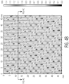
- FIG. 4A One exemplary weave pattern 30 is shown in FIG. 4A .
- the weave pattern generally comprises a single unit cell, which may be combined with other unit cells to form a weave pattern. Unit cells can be repeated as many times as desired in the machine direction and/or the cross-machine direction to form a desired pattern in a papermaking fabric.
- the skilled artisan will be able to envision alternate means of arranging the unit cell of FIG. 4A to create a papermaking fabric having a pattern other than that illustrated in FIG. 4A .
- the weave pattern of FIG. 4A will now be described in detail, however, the principles of weave patterns may be adapted to form a broad range of unit cells that may be combined to form a fabric according to the present invention.
- the weave pattern 30 can include a plurality of warp filaments 14 generally aligned in the machine direction (MD) and a plurality of shute filaments 16 generally aligned in the cross-machine direction (CD).
- MD machine direction
- CD cross-machine direction
- the weave pattern can be configured on a loom (not pictured) such that the resulting web contacting surface of the papermaking fabric will be facing out from the page, and the machine contacting surface of the papermaking fabric will be facing into the page.
- a weave pattern could be configured in the opposite orientation on a loom.
- Each interchange of a specific warp filament 14 and a specific shute filament 16 of the weave pattern 30 that includes a vertical line segment (or a capital letter "I") provides a notation that the warp filament 16 is above top shute (and above bottom shute if present) at that interchange.
- the interchange of warp filament No. 2 and shute filament No. 1 includes such a vertical line segment in FIG. 4A , and thus, warp filament No. 2 is woven above shute filament No. 1.
- shute filament No. 1 is woven above the warp filaments Nos. 9-19 to develop a CD oriented protuberance 38, the presence of which is denoted by a cross-hatching pattern for purposes of clarity of perceiving the CD oriented protuberances.
- the MD oriented protuberances 22 are generally defined by portions of the weave pattern 30 in which a plurality of adjacent warp/shute filament interchanges are woven such that the warp filaments 14 are woven above their respective shute filaments 16.
- the exception being those portions of the protuberance where the shute filament forming a CD oriented protuberance is woven above the protuberance forming warp filaments.
- the shute filament 16a forming the CD oriented protuberance 38a is woven above the warps 14a, 14b forming the MD oriented protuberance 22a.
- the MD oriented protuberances can be of various lengths and/or widths to provide various shapes, as will be discussed in more detail below.
- the MD oriented protuberances are generally spaced apart from one another and may extend continuously across one dimension of the fabric. Further, the MD oriented protuberances may be arranged substantially parallel to one another such that no two MD oriented protuberances intersect one another.
- the weave pattern 30 includes a first MD oriented protuberance 22a which forms a line element and is spaced apart from a second similarly shaped second MD oriented protuberance 22b.
- the width of the valley measured generally in the cross-machine direction (CD), may be from two to ten, such as from four to six, warps wide.
- the valley 24a is three warps wide at its widest point.
- the valley may comprise a variety of different weave patterns to stabilize the resulting fabric and increase the height of the protuberances.
- the valley 24a of FIG. 4A comprises warp/shute filament interchanges in which the warp filaments 14 are woven both above and below their respective shute filaments 16.
- the machine direction (MD) oriented protuberances each comprise a first and a second warp filament - protuberance 22a comprises warps 14a, 14b - arranged in a pair-wise fashion.
- the pair-wise warp filaments 14a, 14b are directly adjacent warps (illustrated as warp positions Nos. 2 and 3) in the weave pattern 30 and make up protuberance forming portions 25a, 25b in which the warp filament 14a, 14b, is woven above its respective shute filament.
- each protuberance forming portion 25 has a first proximal end 17 and first distal end 19 spaced apart in the machine direction (MD).
- the float proximal end 17a can be the interchange of a specific shute filament and a specific warp filament that begins a series of adjacent interchanges in which the warp filaments are woven above that specific shute filament.
- the float distal end 19a can be the interchange of a specific shute filament and a specific warp filament that ends a series of adjacent interchanges in which the warp filaments are woven above that specific shute filament.
- a shute filament float proximal end can be where the shute filament is woven from a web contacting surface to the machine contacting surface of the fabric and a shute filament float distal end can be where the shute filament is woven from a machine contacting surface to the web contacting surface of the fabric.
- the weave pattern 30 is configured such that the pair of adjacent warp filaments 14 overlap one another along a portion of the protuberance 22.
- the overlap portion 36 outlined by the box abcd, is referred to herein as a "paired portion" and comprises a portion of the protuberance 22 where adjacent warp filaments 14b, 14c are woven above the corresponding shute filament.
- the paired portion 36 has a float length of nine (traversing shute position Nos. 12-20), although the length may vary.
- the paired portion may have a float length of two or greater, more preferably three or greater, and still more preferably four or greater, such as from two to twenty and more preferably from two to fourteen and still more preferably from four to ten.
- the length of the MD oriented protuberance forming portions 25, that is the portion of a warp 14 filament woven above the shute 16 floats to form a protuberance 22, may vary.
- the warp shutes forming the protuberance may have a float length greater than 4, such as from 4 to 50, more preferably from 5 to 30 and still more preferably from 7 to 20.
- the shute 14b forming the protuberance forming portion 25a has a float length of nineteen (traversing shute position Nos. 2-20).
- the weave pattern comprises CD oriented protuberances 38 formed from a single shute filament 16 woven above the corresponding warp filament 14.
- the shute filaments 16 forming the CD oriented protuberances 38 are woven in a regular, repeating pattern and yield discrete CD oriented protuberances 38.
- the CD oriented protuberances 38 are arranged in a staggered pattern, spaced apart from one another in the MD by one shute filament 16.
- the CD oriented protuberances 38 have a float length of 11, for example CD oriented protuberance 38a comprises shute filament position No. 21 woven above warp filament 14 position Nos. 11-21.
- the CD oriented protuberances 38 generally traverse two adjacent MD oriented protuberances 22 and form the end walls of valleys 24 disposed there between.
- One skilled in the art will appreciate that the foregoing pattern of weaving CD oriented protuberance is non-limiting and that other patterns may be envisioned.
- the MD oriented protuberances 22 are woven from warp filaments 14 woven above their corresponding shute filaments 16 and are generally aligned with the MD axis of the fabric.
- the weave pattern 30 yields MD oriented protuberances 22 that are continuous in the MD and generally arranged parallel to, and equally spaced apart from, each other.
- MD oriented protuberances generally comprise a plurality of adjacent warp filaments woven above their corresponding shute filaments.
- four immediately adjacent warp filaments 14a-14d form the protuberance.
- the protuberance 22a is woven such that it is a maximum width of four warp filaments and a minimum of one shute filament.
- the MD oriented protuberances 22 are continuous, not discrete, and formed of multiple warp filaments 14 grouped together and supported by multiple shute filaments 16. The longest warp float is over seven shutes. When weaving the pattern 30, two different shute diameters may be utilized, both of which may be larger than the warp diameter even though this is not a requirement of the fabric structure. While the MD oriented protuberances may be aligned with the MD axis, in certain instances the orientation may vary depending on certain factors, such as pick count, and the resulting MD oriented protuberances may be aligned along a slight angle, up to about 15 degrees, with respect to the machine direction.
- the protuberances 22 are spaced apart from one another to define valleys 24 there between.
- the width of the valleys 24 in the illustrated embodiment generally ranges from two to four warp widths.
- the valley sidewalls are generally formed by the spaced apart, adjacent, MD oriented protuberances and the end walls are formed by CD oriented protuberances.
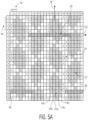
- CD oriented protuberances 38 are formed from a single shute filament 16 woven above its corresponding warp filaments 14 and having a float length of 14. In this manner the CD oriented protuberances 38 may be formed from a shute filament that is woven above the warp filaments 14 forming two adjacent MD oriented protuberances 22. This may result in the CD oriented protuberances having an upper surface lying in an upper surface plane that is above the surface plane defined by the upper surface of the MD oriented protuberances.
- the MD oriented protuberances 22 are woven from warp filaments 14 woven above their corresponding shute filaments 16 and are generally aligned with the MD axis of the fabric.
- the weave pattern 30 yields MD oriented protuberances 22 that are continuous in the MD and generally arranged parallel to, and equally spaced apart from, each other.
- MD oriented protuberances generally comprise a plurality of adjacent warp filaments woven above their corresponding shute filaments.
- the pattern used to form the MD oriented protuberances 22 of FIG. 6A is similar to that FIG. 5A .
- the MD oriented protuberances 22 are continuous, not discrete, and formed of multiple warp filaments 14 grouped together and supported by multiple shute filaments 16. The longest warp float is over seven shutes.
- the protuberances 22 are spaced apart from one another to define valleys 24 there between, which generally have a width from two to four warp widths.
- the valleys 24 are generally continuous and bound on either side by adjacent, spaced apart, MD oriented protuberances 22.
- the CD oriented protuberances 38 generally do not span the entire width of a valley and as such do not form valley end walls.
- the CD oriented protuberances 38 are formed from a single shute filament 16 woven above its corresponding warp filaments 14 and having a float length of seven. In this manner the CD oriented protuberances 38 are formed from a shute filament that is woven above the warp filaments 14 forming only a single MD oriented protuberance 22. This generally results in CD oriented protuberances having a relatively short length (measured along the CD-axis of the element) and an upper surface lying in an upper surface plane that is above the surface plane defined by the upper surface of the MD oriented protuberances. In some embodiments, within a given fabric the protuberances may be woven in different patterns such that some of the protuberances are co-planar and others are out of plane with one another.
- the valley depth and angle, as well as other fabric properties, are measured using a non-contact profilometer as described herein.
- all images are subjected to thresholding to remove the top and bottom 0.5 mm of the scan.
- non-measured points are filled.
- the image is also flattened by applying a rightness filter.
- Profilometry scans of the fabric contacting surface of a sample were created using an FRT MicroSpy ® Profile profilometer (FRT of America, LLC, San Jose, CA) and then analyzing the image using Nanovea ® Ultra software version 7.4 (Nanovea Inc., Irvine, CA). Samples were cut into squares measuring 145 x 145 mm. The samples were then secured to the x-y stage of the profilometer using an aluminum plate having a machined center hole measuring 2 x 2 inches, with the fabric contacting surface of the sample facing upwards, being sure that the samples were laid flat on the stage and not distorted within the profilometer field of view.
- the profilometer was used to generate a three-dimensional height map of the sample surface.
- a 1602 x 1602 array of height values were obtained with a 30 ⁇ spacing resulting in a 48 mm MD x48 mm CD field of view having a vertical resolution 100 nm and a lateral resolution 6 um.
- the resulting height map was exported to .sdf (surface data file) format.
- Valley width is the Psm value having units of mms (mm).
- Valley depth is the difference between C2 and C1 values, also referred to as S90, having units of mms (mm).
- Valley angle is the Pdq value having units of degrees ( ° ).
- the element angle is determined using the "texture direction" function under the "Studies” tab of the Nanovea ® Ultra software. Once the "texture direction” is selected, the angle of the three most elevated features on the fabric surface will be reported. To calculate the element angle, the first value is selected and subtracted from 90. The resulting value is the element angle, having units of degrees.
Landscapes
- Engineering & Computer Science (AREA)
- Textile Engineering (AREA)
- Paper (AREA)
Claims (10)
- Papiermaschinengewebe 10 mit einer Maschinenrichtungsachse und einer Maschinenquerrichtungsachse, das Gewebe umfassend: eine Vielzahl von in Maschinenrichtung (MD) ausgerichteten Kettfäden (14) und eine Vielzahl von in Maschinenquerrichtung (CD) ausgerichteten Schussfäden (16), wobei die Schussfäden mit Kettfäden verwoben sind, um eine maschinenberührende Gewebeseite und eine gegenüberliegende bahnberührende Gewebeseite bereitzustellen, wobei die bahnberührende Gewebeseite eine Vielzahl von in MD ausgerichteten Ausstülpungen (22) aufweist, die aus zwei oder mehr Kettfäden gebildet sind, die über ihren entsprechenden Schussfäden gewebt sind, wobei jede der Vielzahl von in MD ausgerichteten Ausstülpungen voneinander beabstandet ist, um dazwischen Täler (24) zu definieren, und eine Vielzahl von diskreten, in CD ausgerichteten Ausstülpungen (38) aufweist, die aus mindestens einem Schussfaden gebildet sind, der um einen entsprechenden Kettfaden gewebt ist; dadurch gekennzeichnet, dass:
die in CD ausgerichteten Ausstülpungen eine obere Fläche aufweisen, die in einer ersten oberen Flächenebene liegt, und die in MD ausgerichteten Ausstülpungen eine obere Fläche aufweisen, die in einer zweiten oberen Flächenebene liegt, wobei die erste obere Flächenebene über der zweiten oberen Flächenebene liegt. - Papiermaschinengewebe nach Anspruch 1, wobei die Täler fortlaufenden sind; oder
wobei die Täler diskret sind und ein Paar von gegenüberliegenden Endwänden aufweisen, die aus zwei voneinander beabstandeten, in CD ausgerichteten Ausstülpungen gebildet sind, und ein Paar von gegenüberliegenden Seitenwänden aufweisen, die aus zwei voneinander beabstandeten, in MD ausgerichteten Ausstülpungen gebildet sind. - Papiermaschinengewebe nach einem der vorhergehenden Ansprüche, wobei die Vielzahl von in MD ausgerichteten Ausstülpungen parallel zueinander sind.
- Papiermaschinengewebe nach einem der vorhergehenden Ansprüche, wobei jede der Vielzahl von in MD ausgerichteten Ausstülpungen fortlaufend ist; und/oder
wobei jede der Vielzahl von in MD ausgerichteten Ausstülpungen einen Elementwinkel von 0 bis ±20 Grad aufweist, wobei der Elementwinkel die Ausrichtung jeder in MD ausgerichteten Ausstülpung entlang ihrer Längsachse relativ zu der MD-Achse des Gewebes ist, wobei der Elementwinkel wie in dem hierin vorhandenen Abschnitt mit dem Titel "Testverfahren" beschrieben bestimmt wird. - Papiermaschinengewebe nach Anspruch 4, wobei jede der Vielzahl von in MD ausgerichteten Ausstülpungen einen Elementwinkel von 2 bis 10 Grad aufweist, wobei der Elementwinkel wie in dem hierin vorhandenen Abschnitt mit dem Titel "Testverfahren" beschrieben bestimmt wird.
- Papiermaschinengewebe nach einem der vorhergehenden Ansprüche, wobei die Täler eine Tiefe von 0,3 mm oder mehr aufweisen, wobei die Tiefe wie in dem hierin vorhandenen Abschnitt mit dem Titel "Testverfahren" beschrieben bestimmt wird.
- Papiermaschinengewebe nach den Ansprüchen 1-5, wobei die bahnberührende Fläche eine Taltiefe von etwa 0,30 bis etwa 1,00 mm aufweist, wobei die Tiefe wie in dem hierin vorhandenen Abschnitt mit dem Titel "Testverfahren" beschrieben bestimmt wird.
- Papiermaschinengewebe nach einem der vorhergehenden Ansprüche, wobei die Vielzahl von in MD ausgerichteten Ausstülpungen in einem Twillmuster gewebt sind, wobei die Ausstülpungen in MD aus zwei oder mehr direkt angrenzenden Kettfäden gewebt sind, die einen gepaarten Abschnitt mit einer Flottierungslänge von 2 bis 8 aufweisen; und/oderwobei jede der Vielzahl von in MD ausgerichteten Ausstülpungen 2 bis 6 Kettfäden umfasst; und/oderwobei jede der in MD ausgerichteten Ausstülpungen parallel zueinander ist und eine im Wesentlichen ähnliche Höhe und Breite aufweist.
- Papiermaschinengewebe nach einem der vorhergehenden Ansprüche, wobei jede der Vielzahl von diskreten, in CD ausgerichteten Ausstülpungen mindestens eine in MD ausgerichtete Ausstülpung berührt;
wobei vorzugsweise jede der Vielzahl von diskreten, in CD ausgerichteten Ausstülpungen mindestens zwei oder mehr in MD ausgerichtete Ausstülpungen berührt. - Papiermaschinengewebe nach einem der vorhergehenden Ansprüche, wobei jede der Vielzahl von diskreten, in CD ausgerichteten Ausstülpungen parallel zueinander ist und im Wesentlichen ähnliche Längen aufweist.
Applications Claiming Priority (1)
| Application Number | Priority Date | Filing Date | Title |
|---|---|---|---|
| PCT/US2018/053271 WO2020068091A1 (en) | 2018-09-28 | 2018-09-28 | Woven papermaking fabric having discrete cross-machine direction protuberances |
Publications (3)
| Publication Number | Publication Date |
|---|---|
| EP3856961A1 EP3856961A1 (de) | 2021-08-04 |
| EP3856961A4 EP3856961A4 (de) | 2022-05-04 |
| EP3856961B1 true EP3856961B1 (de) | 2024-12-04 |
Family
ID=69952731
Family Applications (1)
| Application Number | Title | Priority Date | Filing Date |
|---|---|---|---|
| EP18935691.8A Active EP3856961B1 (de) | 2018-09-28 | 2018-09-28 | Gewebe für die papierherstellung mit diskreten ausstülpungen quer zur maschinenrichtung |
Country Status (4)
| Country | Link |
|---|---|
| US (1) | US11920302B2 (de) |
| EP (1) | EP3856961B1 (de) |
| CN (1) | CN112739861A (de) |
| WO (1) | WO2020068091A1 (de) |
Families Citing this family (8)
| Publication number | Priority date | Publication date | Assignee | Title |
|---|---|---|---|---|
| EP3688212B1 (de) | 2017-09-29 | 2025-07-09 | Kimberly-Clark Worldwide, Inc. | Papiererzeugungsgewebe mit köperbindung |
| WO2019067685A1 (en) | 2017-09-29 | 2019-04-04 | Kimberly-Clark Worldwide, Inc. | WOVEN FABRIC FOR MANUFACTURING PAPER HAVING CONVERGENT, DIVERGENT, OR FUSED TOPOGRAPHY |
| WO2019067690A1 (en) | 2017-09-29 | 2019-04-04 | Kimberly-Clark Worldwide, Inc. | PAPER MAKING FABRIC HAVING ORIENTED TOPOGRAPHY IN MANUFACTURING DIRECTION AND PERPENDICULAR TO MANUFACTURING DIRECTION |
| MX2020002588A (es) | 2017-09-29 | 2020-07-20 | Kimberly Clark Co | Tela tejida para la fabricacion de papel que incluye tejido estabilizado que proporciona una superficie de contacto texturizada. |
| CN112739861A (zh) | 2018-09-28 | 2021-04-30 | 金伯利-克拉克环球有限公司 | 具有离散的横向突起的机织造纸织物 |
| WO2020068092A1 (en) | 2018-09-28 | 2020-04-02 | Kimberly-Clark Worldwide, Inc. | Woven papermaking fabric having intersecting twill patterns |
| US12188178B2 (en) * | 2022-12-07 | 2025-01-07 | Voith Patent Gmbh | Structured fabric with discrete elements |
| EP4705563A1 (de) * | 2023-05-04 | 2026-03-11 | Kimberly-Clark Worldwide, Inc. | Papiermaschinengewebe |
Family Cites Families (53)
| Publication number | Priority date | Publication date | Assignee | Title |
|---|---|---|---|---|
| US4191609A (en) * | 1979-03-09 | 1980-03-04 | The Procter & Gamble Company | Soft absorbent imprinted paper sheet and method of manufacture thereof |
| US5240763A (en) * | 1989-05-12 | 1993-08-31 | Asten Group, Inc. | Dimensionally stable papermakers fabric |
| US5199467A (en) * | 1990-06-06 | 1993-04-06 | Asten Group, Inc. | Papermakers fabric with stacked machine direction yarns |
| US5228482A (en) * | 1992-07-06 | 1993-07-20 | Wangner Systems Corporation | Papermaking fabric with diagonally arranged pockets |
| US5456293A (en) * | 1994-08-01 | 1995-10-10 | Wangner Systems Corporation | Woven papermaking fabric with diagonally arranged pockets and troughs |
| US5520225A (en) * | 1995-01-23 | 1996-05-28 | Wangner Systems Corp. | Pocket arrangement in the support surface of a woven papermaking fabric |
| US5552007A (en) * | 1995-01-31 | 1996-09-03 | Kimberly-Clark Corporation | Conveying continous web having cross-direction tension |
| US5832962A (en) * | 1995-12-29 | 1998-11-10 | Kimberly-Clark Worldwide, Inc. | System for making absorbent paper products |
| US5713397A (en) * | 1996-08-09 | 1998-02-03 | Wangner Systems Corporation | Multi-layered through air drying fabric |
| US5817400A (en) * | 1996-11-27 | 1998-10-06 | Kimberly-Clark Worldwide, Inc. | Absorbent articles with reduced cross-directional wrinkles |
| US7935409B2 (en) * | 1998-08-06 | 2011-05-03 | Kimberly-Clark Worldwide, Inc. | Tissue sheets having improved properties |
| ZA200007449B (en) | 1998-08-06 | 2001-06-14 | Kimberly Clark Co | Rolls of tissue sheets having improved properties. |
| US6237644B1 (en) * | 1998-09-01 | 2001-05-29 | Stewart Lister Hay | Tissue forming fabrics |
| PT1035251E (pt) * | 1999-03-12 | 2002-06-28 | Heimbach Gmbh Thomas Josef | Banda de drenagem para maquina de fabrico de papel |
| DE19917832C2 (de) | 1999-04-20 | 2001-09-13 | Sca Hygiene Prod Gmbh | Papiermaschinen-Bespannung sowie damit hergestelltes Tissue-Papier |
| DE19917869C2 (de) * | 1999-04-20 | 2003-05-22 | Sca Hygiene Prod Gmbh | Papiermaschinen-Bespannung sowie damit hergestelltes Tissue-Papier |
| US6610619B2 (en) * | 1999-12-29 | 2003-08-26 | Kimberly-Clark Worldwide, Inc. | Patterned felts for bulk and visual aesthetic development of a tissue basesheet |
| US6660362B1 (en) * | 2000-11-03 | 2003-12-09 | Kimberly-Clark Worldwide, Inc. | Deflection members for tissue production |
| US6763855B2 (en) * | 2001-10-30 | 2004-07-20 | Albany International Corp. | Through-air-drying base fabric |
| US6790314B2 (en) * | 2001-11-02 | 2004-09-14 | Kimberly-Clark Worldwide, Inc. | Fabric for use in the manufacture of tissue products having visually discernable background texture regions bordered by curvilinear decorative elements and method thereof |
| US7235156B2 (en) * | 2001-11-27 | 2007-06-26 | Kimberly-Clark Worldwide, Inc. | Method for reducing nesting in paper products and paper products formed therefrom |
| US6673202B2 (en) * | 2002-02-15 | 2004-01-06 | Kimberly-Clark Worldwide, Inc. | Wide wale tissue sheets and method of making same |
| US6991706B2 (en) * | 2003-09-02 | 2006-01-31 | Kimberly-Clark Worldwide, Inc. | Clothlike pattern densified web |
| US7294229B2 (en) * | 2003-12-23 | 2007-11-13 | Kimberly-Clark Worldwide, Inc. | Tissue products having substantially equal machine direction and cross-machine direction mechanical properties |
| US7300543B2 (en) | 2003-12-23 | 2007-11-27 | Kimberly-Clark Worldwide, Inc. | Tissue products having high durability and a deep discontinuous pocket structure |
| US7323072B2 (en) * | 2005-04-27 | 2008-01-29 | Kimberly-Clark Worldwide, Inc. | Multi-roll bonding and aperturing |
| CN2885922Y (zh) * | 2005-11-25 | 2007-04-04 | 江苏金呢集团有限公司 | 造纸用无网痕二层半成形网 |
| CA2645298A1 (en) * | 2006-03-10 | 2007-09-20 | Astenjohnson, Inc. | Double layer papermakers fabric with pockets for bulk enhancement |
| US20080023169A1 (en) | 2006-07-14 | 2008-01-31 | Fernandes Lippi A | Forming fabric with extended surface |
| US7611607B2 (en) * | 2006-10-27 | 2009-11-03 | Voith Patent Gmbh | Rippled papermaking fabrics for creped and uncreped tissue manufacturing processes |
| WO2008073301A2 (en) * | 2006-12-08 | 2008-06-19 | Astenjohnson, Inc. | Machine side layer weave design for composite forming fabrics |
| US7879193B2 (en) * | 2007-09-06 | 2011-02-01 | Voith Patent Gmbh | Structured forming fabric and method |
| US8043477B2 (en) | 2008-02-25 | 2011-10-25 | Voith Patent Gmbh | Belt and method of making a belt for a paper making machine |
| CA2748789A1 (en) | 2011-08-15 | 2013-02-15 | Derek Chaplin | Embossing fabric including warp yarn sets |
| US9422666B2 (en) * | 2011-09-27 | 2016-08-23 | Astenjohnson, Inc. | Ten-shed semi-duplex through-air dryer fabric |
| WO2014054021A1 (en) * | 2012-10-05 | 2014-04-10 | Kimberly-Clark Worldwide, Inc. | Personal care cleaning article |
| DE102013108399B3 (de) * | 2013-08-05 | 2014-11-27 | ANDRITZ KUFFERATH GmbH | Papiermaschinensieb, dessen laufseite querfäden mit unterschiedlicher flottierungslänge aufweist |
| JP5814330B2 (ja) | 2013-12-02 | 2015-11-17 | 日本フエルト株式会社 | 抄紙用織物 |
| MX370994B (es) * | 2014-04-02 | 2020-01-13 | Essity Hygiene & Health Ab | Producto de papel absorbente y método para la elaboración de tal producto de papel absorbente. |
| CN206438338U (zh) | 2015-09-10 | 2017-08-25 | 日本惠尔得株式会社 | 抄纸用织物 |
| GB2564820B (en) * | 2016-05-09 | 2021-03-03 | Kimberly Clark Co | Texture subtractive patterning |
| US10385511B2 (en) * | 2016-07-28 | 2019-08-20 | Kimberly-Clark Worldwide, Inc. | Three-dimensional papermaking belt |
| CN109689351A (zh) * | 2016-09-30 | 2019-04-26 | 金伯利-克拉克环球有限公司 | 具有印刷纹理的清洁制品 |
| WO2018125653A1 (en) * | 2016-12-30 | 2018-07-05 | Kimberly-Clark Worldwide, Inc. | Papermaking fabric including textured contacting surface |
| EP3688212B1 (de) * | 2017-09-29 | 2025-07-09 | Kimberly-Clark Worldwide, Inc. | Papiererzeugungsgewebe mit köperbindung |
| WO2019067690A1 (en) * | 2017-09-29 | 2019-04-04 | Kimberly-Clark Worldwide, Inc. | PAPER MAKING FABRIC HAVING ORIENTED TOPOGRAPHY IN MANUFACTURING DIRECTION AND PERPENDICULAR TO MANUFACTURING DIRECTION |
| WO2019067685A1 (en) * | 2017-09-29 | 2019-04-04 | Kimberly-Clark Worldwide, Inc. | WOVEN FABRIC FOR MANUFACTURING PAPER HAVING CONVERGENT, DIVERGENT, OR FUSED TOPOGRAPHY |
| MX2020002588A (es) * | 2017-09-29 | 2020-07-20 | Kimberly Clark Co | Tela tejida para la fabricacion de papel que incluye tejido estabilizado que proporciona una superficie de contacto texturizada. |
| MX2020004351A (es) * | 2017-11-30 | 2020-08-13 | Kimberly Clark Co | Papel tisu texturizado suave. |
| WO2019133875A1 (en) * | 2017-12-29 | 2019-07-04 | Kimberly-Clark Worldwide, Inc. | Three-dimensional papermaking belt |
| CN112739861A (zh) * | 2018-09-28 | 2021-04-30 | 金伯利-克拉克环球有限公司 | 具有离散的横向突起的机织造纸织物 |
| WO2020068092A1 (en) | 2018-09-28 | 2020-04-02 | Kimberly-Clark Worldwide, Inc. | Woven papermaking fabric having intersecting twill patterns |
| US10927506B2 (en) * | 2018-11-30 | 2021-02-23 | Kimberly-Clark Worldwide, Inc. | Papermaking fabrics having machine and cross-machine direction elements and paper products made therewith |
-
2018
- 2018-09-28 CN CN201880097863.1A patent/CN112739861A/zh active Pending
- 2018-09-28 US US17/279,423 patent/US11920302B2/en active Active
- 2018-09-28 WO PCT/US2018/053271 patent/WO2020068091A1/en not_active Ceased
- 2018-09-28 EP EP18935691.8A patent/EP3856961B1/de active Active
Also Published As
| Publication number | Publication date |
|---|---|
| CN112739861A (zh) | 2021-04-30 |
| WO2020068091A1 (en) | 2020-04-02 |
| US11920302B2 (en) | 2024-03-05 |
| US20220010491A1 (en) | 2022-01-13 |
| EP3856961A1 (de) | 2021-08-04 |
| EP3856961A4 (de) | 2022-05-04 |
Similar Documents
| Publication | Publication Date | Title |
|---|---|---|
| US11920302B2 (en) | Woven papermaking fabric having discrete cross-machine direction protuberances | |
| US12180653B2 (en) | Woven papermaking fabric having converging, diverging or merging topography | |
| EP3856960B1 (de) | Papiermaschinengewebe mit sich kreuzenden köpermustern | |
| AU2018273341B2 (en) | Structured papermaking fabric | |
| US12168851B2 (en) | Woven papermaking fabric having machine and cross-machine oriented topography | |
| EP3688212B1 (de) | Papiererzeugungsgewebe mit köperbindung | |
| AU2017386370B2 (en) | Papermaking fabric including textured contacting surface | |
| AU2023446477A1 (en) | Woven papermaking fabrics |
Legal Events
| Date | Code | Title | Description |
|---|---|---|---|
| STAA | Information on the status of an ep patent application or granted ep patent |
Free format text: STATUS: THE INTERNATIONAL PUBLICATION HAS BEEN MADE |
|
| PUAI | Public reference made under article 153(3) epc to a published international application that has entered the european phase |
Free format text: ORIGINAL CODE: 0009012 |
|
| STAA | Information on the status of an ep patent application or granted ep patent |
Free format text: STATUS: REQUEST FOR EXAMINATION WAS MADE |
|
| 17P | Request for examination filed |
Effective date: 20210409 |
|
| AK | Designated contracting states |
Kind code of ref document: A1 Designated state(s): AL AT BE BG CH CY CZ DE DK EE ES FI FR GB GR HR HU IE IS IT LI LT LU LV MC MK MT NL NO PL PT RO RS SE SI SK SM TR |
|
| DAV | Request for validation of the european patent (deleted) | ||
| DAX | Request for extension of the european patent (deleted) | ||
| REG | Reference to a national code |
Ref country code: DE Ref legal event code: R079 Free format text: PREVIOUS MAIN CLASS: D03D0013000000 Ipc: D21F0001000000 Ref document number: 602018077408 Country of ref document: DE |
|
| A4 | Supplementary search report drawn up and despatched |
Effective date: 20220404 |
|
| RIC1 | Information provided on ipc code assigned before grant |
Ipc: D21F 11/00 20060101ALI20220328BHEP Ipc: D21F 7/08 20060101ALI20220328BHEP Ipc: D21F 5/18 20060101ALI20220328BHEP Ipc: D21F 1/00 20060101AFI20220328BHEP |
|
| STAA | Information on the status of an ep patent application or granted ep patent |
Free format text: STATUS: EXAMINATION IS IN PROGRESS |
|
| 17Q | First examination report despatched |
Effective date: 20230824 |
|
| GRAP | Despatch of communication of intention to grant a patent |
Free format text: ORIGINAL CODE: EPIDOSNIGR1 |
|
| STAA | Information on the status of an ep patent application or granted ep patent |
Free format text: STATUS: GRANT OF PATENT IS INTENDED |
|
| INTG | Intention to grant announced |
Effective date: 20240624 |
|
| GRAS | Grant fee paid |
Free format text: ORIGINAL CODE: EPIDOSNIGR3 |
|
| GRAA | (expected) grant |
Free format text: ORIGINAL CODE: 0009210 |
|
| STAA | Information on the status of an ep patent application or granted ep patent |
Free format text: STATUS: THE PATENT HAS BEEN GRANTED |
|
| AK | Designated contracting states |
Kind code of ref document: B1 Designated state(s): AL AT BE BG CH CY CZ DE DK EE ES FI FR GB GR HR HU IE IS IT LI LT LU LV MC MK MT NL NO PL PT RO RS SE SI SK SM TR |
|
| RAP3 | Party data changed (applicant data changed or rights of an application transferred) |
Owner name: KIMBERLY-CLARK WORLDWIDE, INC. |
|
| REG | Reference to a national code |
Ref country code: GB Ref legal event code: FG4D |
|
| REG | Reference to a national code |
Ref country code: CH Ref legal event code: EP |
|
| REG | Reference to a national code |
Ref country code: DE Ref legal event code: R096 Ref document number: 602018077408 Country of ref document: DE |
|
| REG | Reference to a national code |
Ref country code: IE Ref legal event code: FG4D |
|
| P01 | Opt-out of the competence of the unified patent court (upc) registered |
Free format text: CASE NUMBER: APP_63872/2024 Effective date: 20241202 |
|
| REG | Reference to a national code |
Ref country code: LT Ref legal event code: MG9D |
|
| REG | Reference to a national code |
Ref country code: NL Ref legal event code: MP Effective date: 20241204 |
|
| PG25 | Lapsed in a contracting state [announced via postgrant information from national office to epo] |
Ref country code: HR Free format text: LAPSE BECAUSE OF FAILURE TO SUBMIT A TRANSLATION OF THE DESCRIPTION OR TO PAY THE FEE WITHIN THE PRESCRIBED TIME-LIMIT Effective date: 20241204 |
|
| PG25 | Lapsed in a contracting state [announced via postgrant information from national office to epo] |
Ref country code: FI Free format text: LAPSE BECAUSE OF FAILURE TO SUBMIT A TRANSLATION OF THE DESCRIPTION OR TO PAY THE FEE WITHIN THE PRESCRIBED TIME-LIMIT Effective date: 20241204 |
|
| PG25 | Lapsed in a contracting state [announced via postgrant information from national office to epo] |
Ref country code: BG Free format text: LAPSE BECAUSE OF FAILURE TO SUBMIT A TRANSLATION OF THE DESCRIPTION OR TO PAY THE FEE WITHIN THE PRESCRIBED TIME-LIMIT Effective date: 20241204 |
|
| PG25 | Lapsed in a contracting state [announced via postgrant information from national office to epo] |
Ref country code: ES Free format text: LAPSE BECAUSE OF FAILURE TO SUBMIT A TRANSLATION OF THE DESCRIPTION OR TO PAY THE FEE WITHIN THE PRESCRIBED TIME-LIMIT Effective date: 20241204 |
|
| PG25 | Lapsed in a contracting state [announced via postgrant information from national office to epo] |
Ref country code: NO Free format text: LAPSE BECAUSE OF FAILURE TO SUBMIT A TRANSLATION OF THE DESCRIPTION OR TO PAY THE FEE WITHIN THE PRESCRIBED TIME-LIMIT Effective date: 20250304 |
|
| PG25 | Lapsed in a contracting state [announced via postgrant information from national office to epo] |
Ref country code: GR Free format text: LAPSE BECAUSE OF FAILURE TO SUBMIT A TRANSLATION OF THE DESCRIPTION OR TO PAY THE FEE WITHIN THE PRESCRIBED TIME-LIMIT Effective date: 20250305 Ref country code: LV Free format text: LAPSE BECAUSE OF FAILURE TO SUBMIT A TRANSLATION OF THE DESCRIPTION OR TO PAY THE FEE WITHIN THE PRESCRIBED TIME-LIMIT Effective date: 20241204 |
|
| PG25 | Lapsed in a contracting state [announced via postgrant information from national office to epo] |
Ref country code: RS Free format text: LAPSE BECAUSE OF FAILURE TO SUBMIT A TRANSLATION OF THE DESCRIPTION OR TO PAY THE FEE WITHIN THE PRESCRIBED TIME-LIMIT Effective date: 20250304 |
|
| PG25 | Lapsed in a contracting state [announced via postgrant information from national office to epo] |
Ref country code: NL Free format text: LAPSE BECAUSE OF FAILURE TO SUBMIT A TRANSLATION OF THE DESCRIPTION OR TO PAY THE FEE WITHIN THE PRESCRIBED TIME-LIMIT Effective date: 20241204 |
|
| PG25 | Lapsed in a contracting state [announced via postgrant information from national office to epo] |
Ref country code: SM Free format text: LAPSE BECAUSE OF FAILURE TO SUBMIT A TRANSLATION OF THE DESCRIPTION OR TO PAY THE FEE WITHIN THE PRESCRIBED TIME-LIMIT Effective date: 20241204 |
|
| PG25 | Lapsed in a contracting state [announced via postgrant information from national office to epo] |
Ref country code: PL Free format text: LAPSE BECAUSE OF FAILURE TO SUBMIT A TRANSLATION OF THE DESCRIPTION OR TO PAY THE FEE WITHIN THE PRESCRIBED TIME-LIMIT Effective date: 20241204 |
|
| PG25 | Lapsed in a contracting state [announced via postgrant information from national office to epo] |
Ref country code: IS Free format text: LAPSE BECAUSE OF FAILURE TO SUBMIT A TRANSLATION OF THE DESCRIPTION OR TO PAY THE FEE WITHIN THE PRESCRIBED TIME-LIMIT Effective date: 20250404 |
|
| PG25 | Lapsed in a contracting state [announced via postgrant information from national office to epo] |
Ref country code: PT Free format text: LAPSE BECAUSE OF FAILURE TO SUBMIT A TRANSLATION OF THE DESCRIPTION OR TO PAY THE FEE WITHIN THE PRESCRIBED TIME-LIMIT Effective date: 20250404 |
|
| PG25 | Lapsed in a contracting state [announced via postgrant information from national office to epo] |
Ref country code: EE Free format text: LAPSE BECAUSE OF FAILURE TO SUBMIT A TRANSLATION OF THE DESCRIPTION OR TO PAY THE FEE WITHIN THE PRESCRIBED TIME-LIMIT Effective date: 20241204 |
|
| PG25 | Lapsed in a contracting state [announced via postgrant information from national office to epo] |
Ref country code: RO Free format text: LAPSE BECAUSE OF FAILURE TO SUBMIT A TRANSLATION OF THE DESCRIPTION OR TO PAY THE FEE WITHIN THE PRESCRIBED TIME-LIMIT Effective date: 20241204 |
|
| PG25 | Lapsed in a contracting state [announced via postgrant information from national office to epo] |
Ref country code: SK Free format text: LAPSE BECAUSE OF FAILURE TO SUBMIT A TRANSLATION OF THE DESCRIPTION OR TO PAY THE FEE WITHIN THE PRESCRIBED TIME-LIMIT Effective date: 20241204 |
|
| PG25 | Lapsed in a contracting state [announced via postgrant information from national office to epo] |
Ref country code: CZ Free format text: LAPSE BECAUSE OF FAILURE TO SUBMIT A TRANSLATION OF THE DESCRIPTION OR TO PAY THE FEE WITHIN THE PRESCRIBED TIME-LIMIT Effective date: 20241204 |
|
| PG25 | Lapsed in a contracting state [announced via postgrant information from national office to epo] |
Ref country code: IT Free format text: LAPSE BECAUSE OF FAILURE TO SUBMIT A TRANSLATION OF THE DESCRIPTION OR TO PAY THE FEE WITHIN THE PRESCRIBED TIME-LIMIT Effective date: 20241204 |
|
| REG | Reference to a national code |
Ref country code: DE Ref legal event code: R097 Ref document number: 602018077408 Country of ref document: DE |
|
| PG25 | Lapsed in a contracting state [announced via postgrant information from national office to epo] |
Ref country code: SE Free format text: LAPSE BECAUSE OF FAILURE TO SUBMIT A TRANSLATION OF THE DESCRIPTION OR TO PAY THE FEE WITHIN THE PRESCRIBED TIME-LIMIT Effective date: 20241204 |
|
| PG25 | Lapsed in a contracting state [announced via postgrant information from national office to epo] |
Ref country code: DK Free format text: LAPSE BECAUSE OF FAILURE TO SUBMIT A TRANSLATION OF THE DESCRIPTION OR TO PAY THE FEE WITHIN THE PRESCRIBED TIME-LIMIT Effective date: 20241204 |
|
| PGFP | Annual fee paid to national office [announced via postgrant information from national office to epo] |
Ref country code: DE Payment date: 20250929 Year of fee payment: 8 |
|
| PLBE | No opposition filed within time limit |
Free format text: ORIGINAL CODE: 0009261 |
|
| STAA | Information on the status of an ep patent application or granted ep patent |
Free format text: STATUS: NO OPPOSITION FILED WITHIN TIME LIMIT |
|
| REG | Reference to a national code |
Ref country code: CH Ref legal event code: L10 Free format text: ST27 STATUS EVENT CODE: U-0-0-L10-L00 (AS PROVIDED BY THE NATIONAL OFFICE) Effective date: 20251015 |
|
| PGFP | Annual fee paid to national office [announced via postgrant information from national office to epo] |
Ref country code: AT Payment date: 20250929 Year of fee payment: 8 |
|
| 26N | No opposition filed |
Effective date: 20250905 |
|
| REG | Reference to a national code |
Ref country code: AT Ref legal event code: UEP Ref document number: 1748270 Country of ref document: AT Kind code of ref document: T Effective date: 20241204 |
|
| REG | Reference to a national code |
Ref country code: CH Ref legal event code: H13 Free format text: ST27 STATUS EVENT CODE: U-0-0-H10-H13 (AS PROVIDED BY THE NATIONAL OFFICE) Effective date: 20260504 |